
Elastic–Plastic Mechanical Behavior Analysis of a Nb3Sn Superconducting Strand with Initial Thermal Damage


Abstract
1. Introduction
2. Numerical Analysis of the Constitutive Relationship of EAS-Nb3Sn Strands
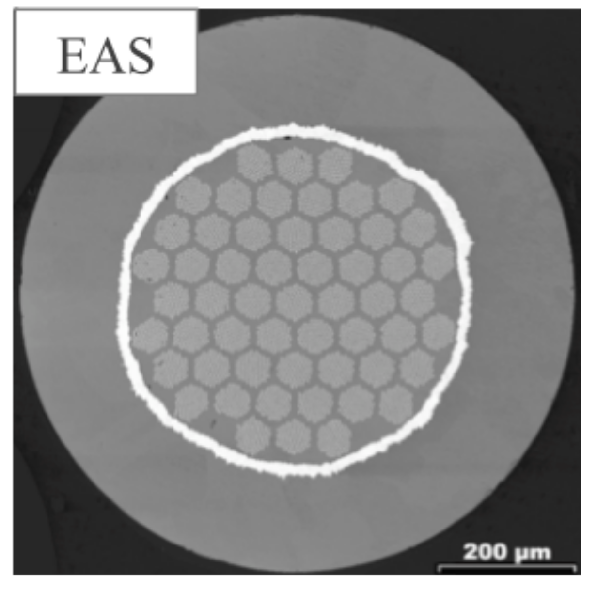
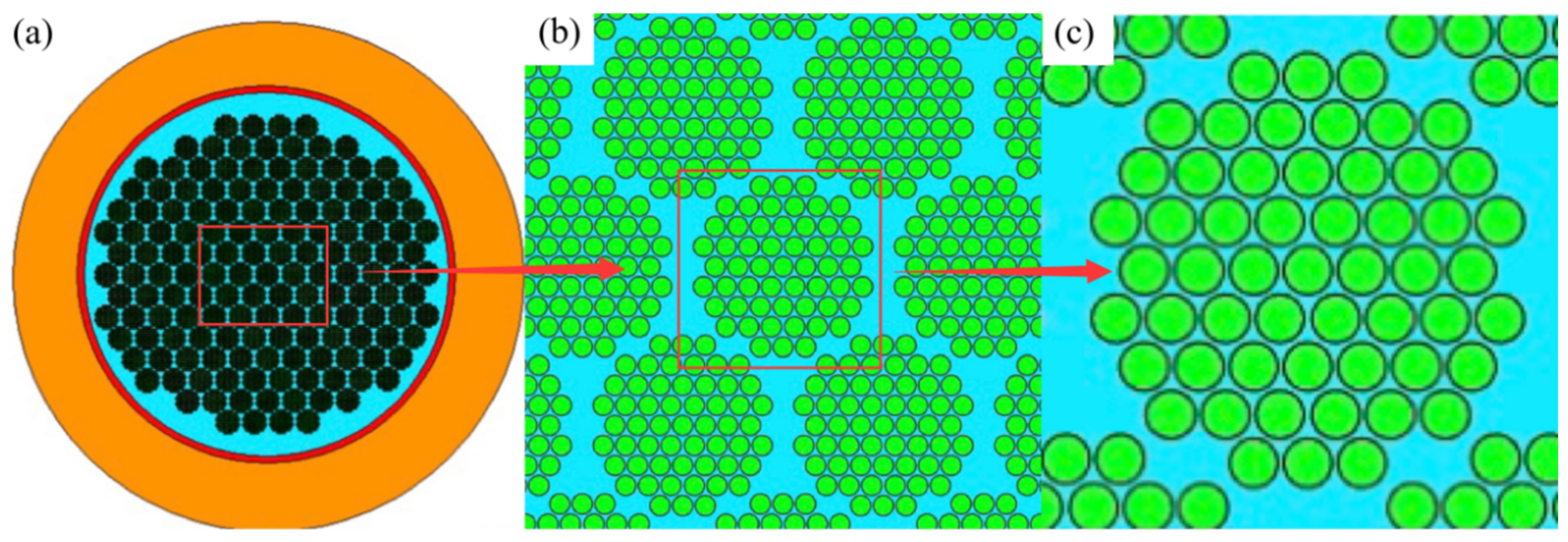
2.1. The Hierarchical Homogenization Model of EAS-Nb3Sn Strands
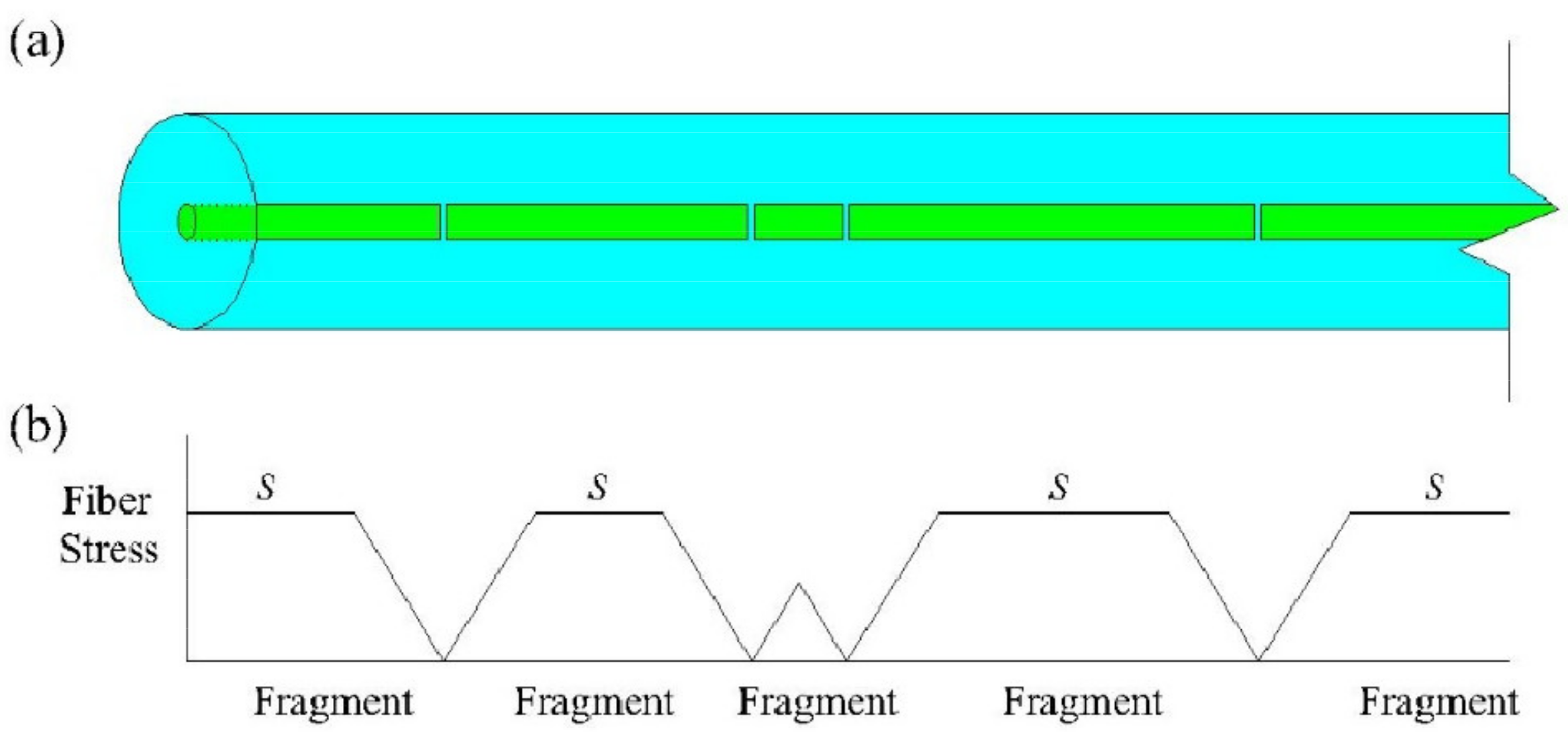
2.2. Fiber Damage Caused by Thermal Stress
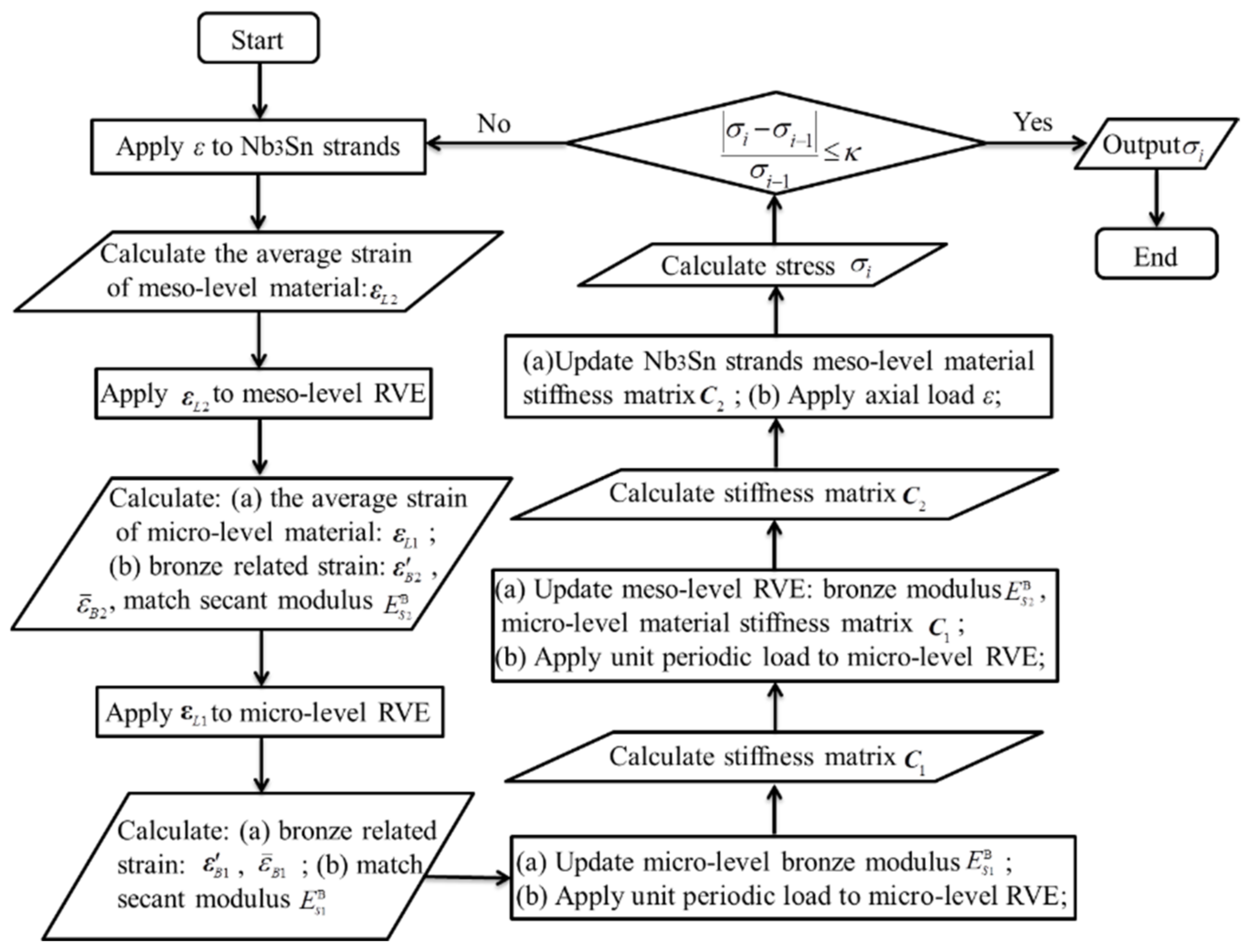
2.3. Nb3Sn Strand Elastoplastic Uniaxial Tensile Study with Fiber Damage
- 1.
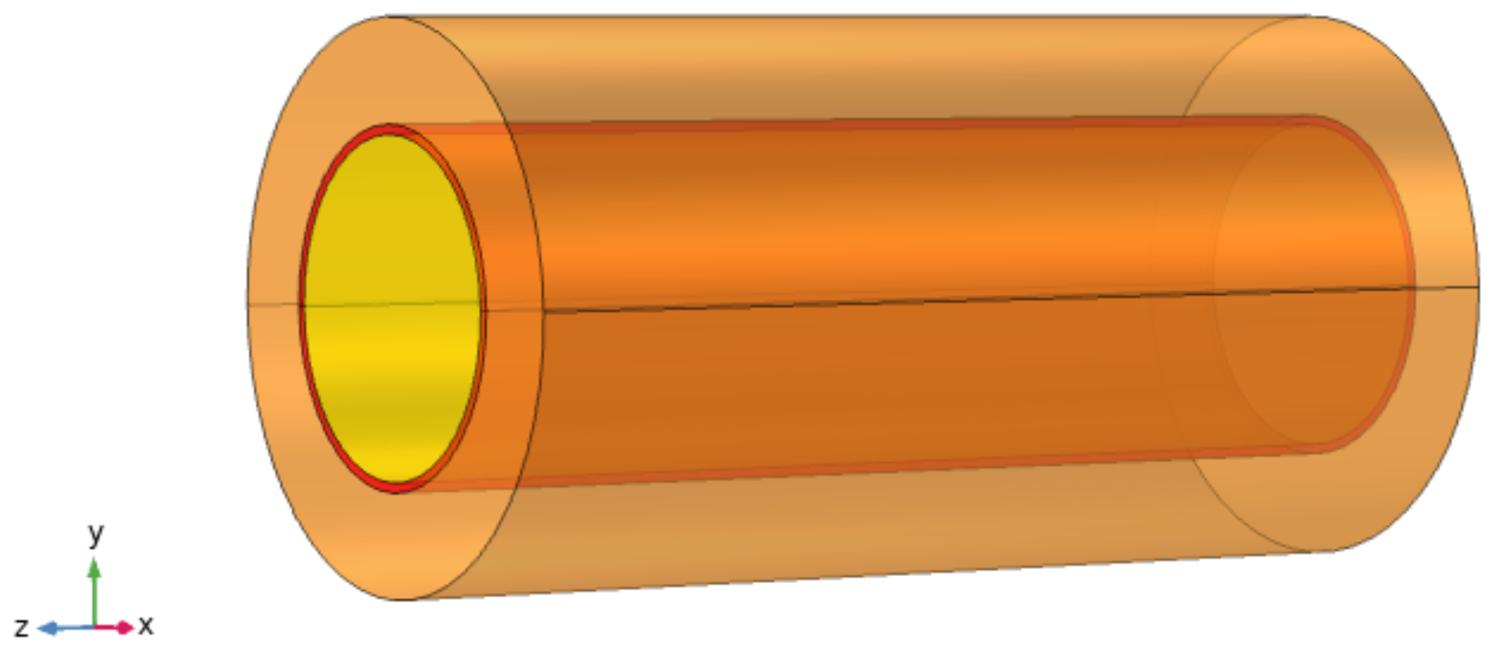
- Apply uniaxial tensile strain, εz, to the EAS-Nb3Sn strand by fixing the axial displacements pointwise at the left end:and the axial displacements pointwise at the left end:While considering the fiber damage and plasticity of copper, then calculate and output the average strain tensor, , of level 2 homogenization part of the strand.
- 2.
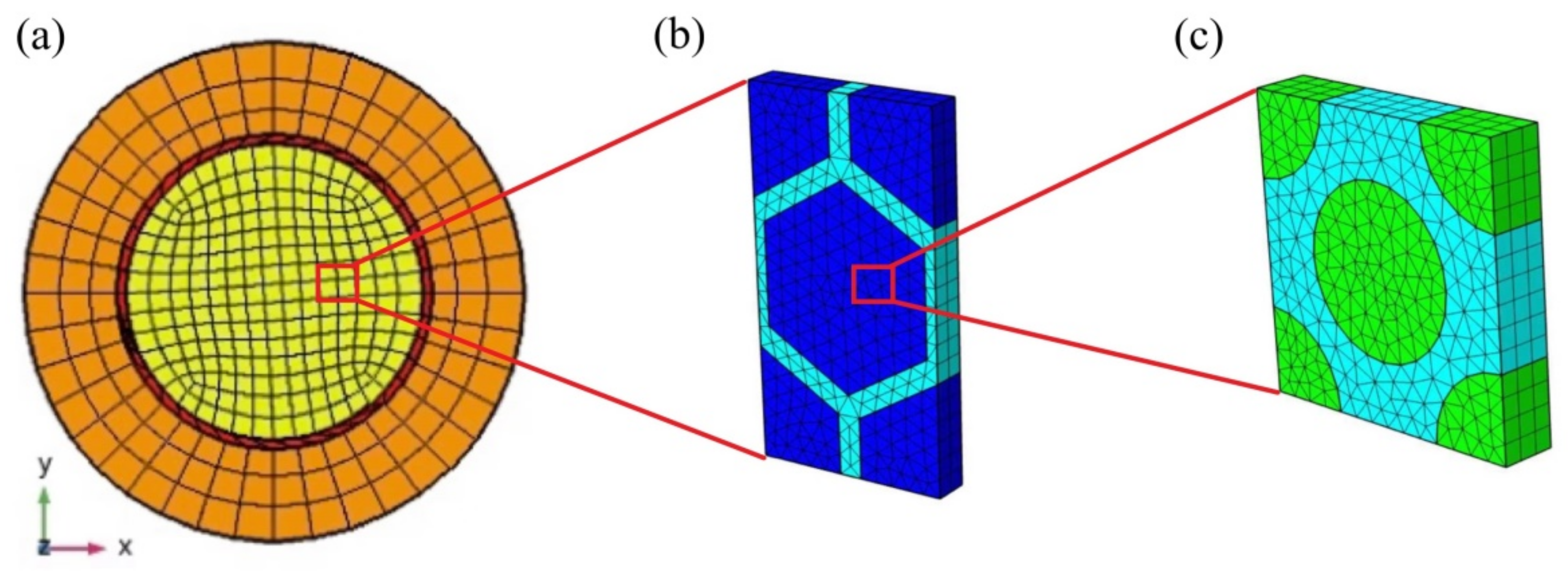
- Apply to level 2 RVE (Figure 3b) by setting the displacements of the points on the level 2 RVE surface:in which xj (j = 1, 2, 3) are the x, y, and z coordinate values. ui (i = 1, 2, 3) represents the displacements along the x, y, and z directions. Calculate and output the average strain, , of the level 1 homogeneous part of the strand and the deviant strain, , of the bronze matrix.
- 3.
- Apply to the level 1 RVE (Figure 3c) by setting the displacements of the points on the level 2 RVE surface:where, xj and ui are the x, y, and z coordinate values and displacements in the corresponding directions, respectively. Calculate and output the deviant strain, , of the first-class bronze matrix.
- 1.
- Update the secant modulus of the level 1 bronze and apply the periodic boundary conditions to the level 1 RVE; calculate and output the stiffness matrix, C1.
- 2.
- Update the secant modulus of the secondary bronze and the stiffness matrix, C1, of the homogeneous part of the strand in the level 1 RVE, apply the periodic boundary conditions to level 2 RVE, and calculate and output the stiffness matrix, C2.
- 3.
- Update the stiffness matrix, C2, of the level 2 homogenization part of the strand in the EAS-Nb3Sn strand model, apply the uniaxial tensile load, εz, and then calculate and output the stress values.
3. Multi-Scale Numerical Analysis of EAS-Nb3Sn Strands
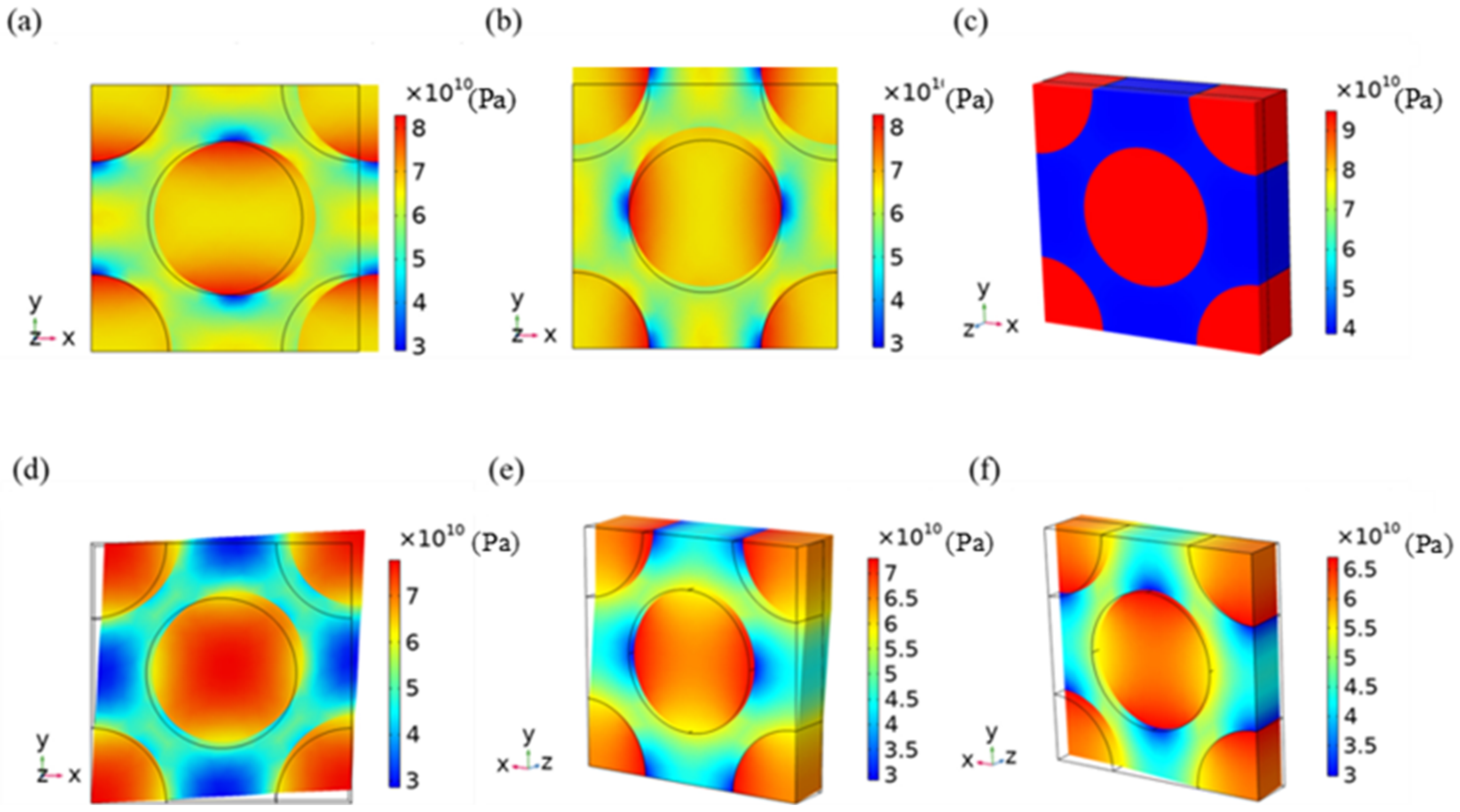
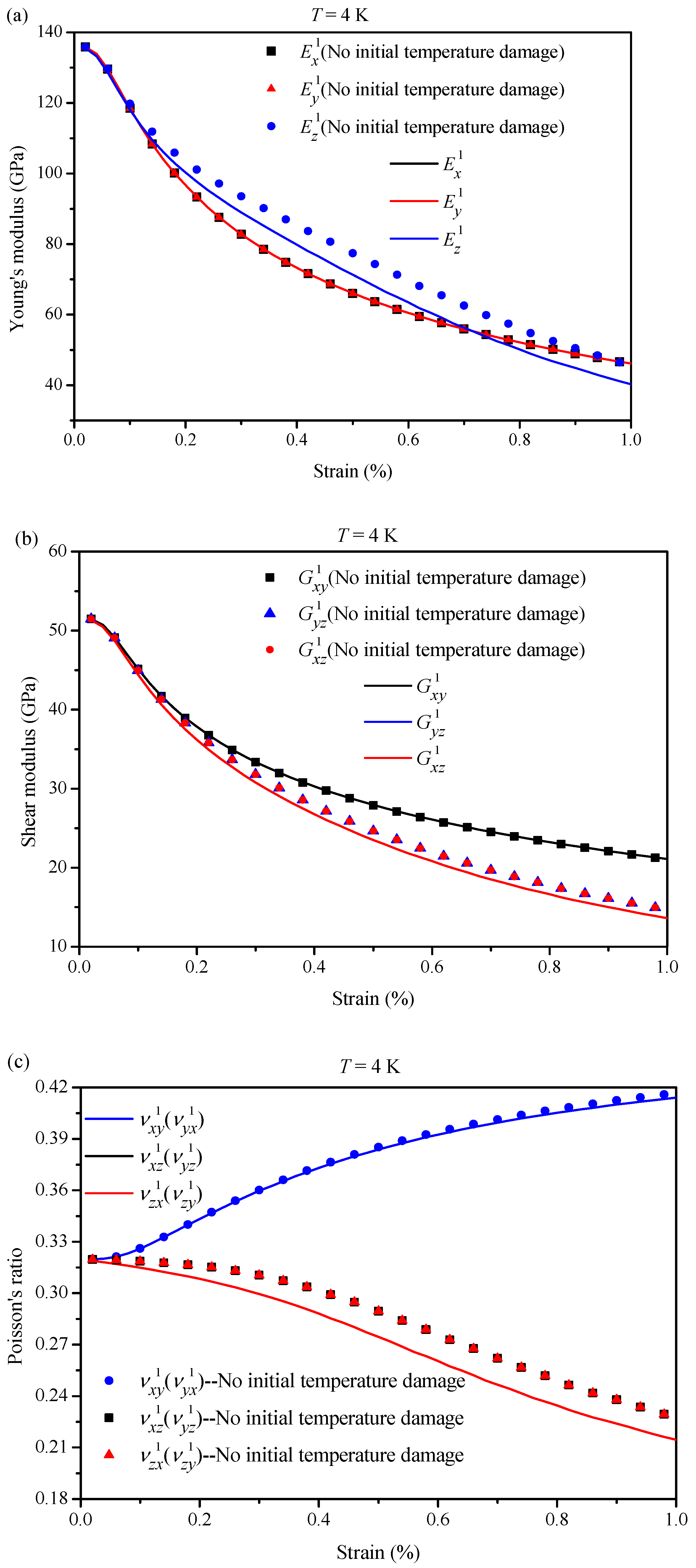
3.1. The Effective Elastic–Plastic Parameters of the Level 1 Homogeneous Fiber Bundles
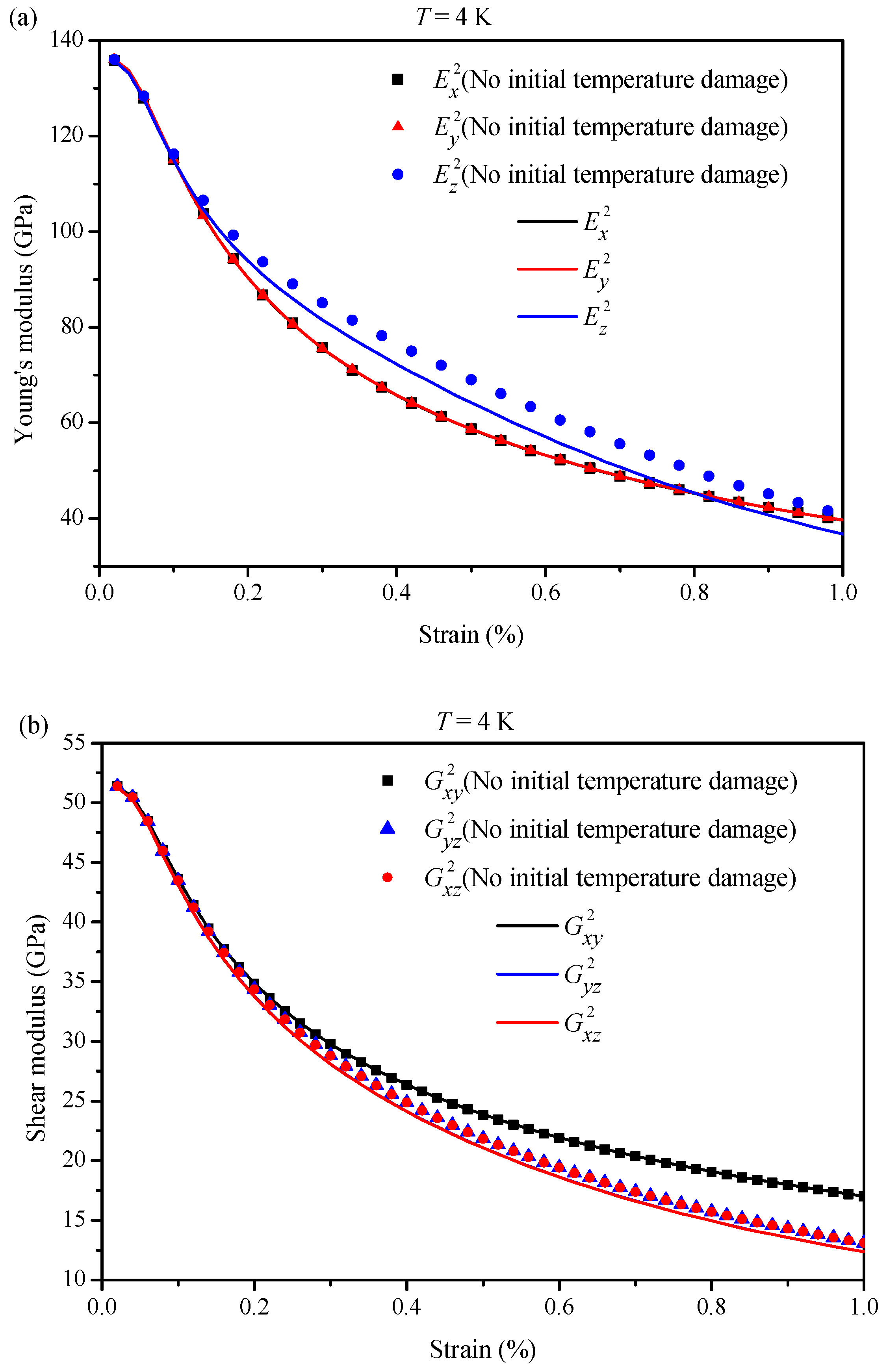
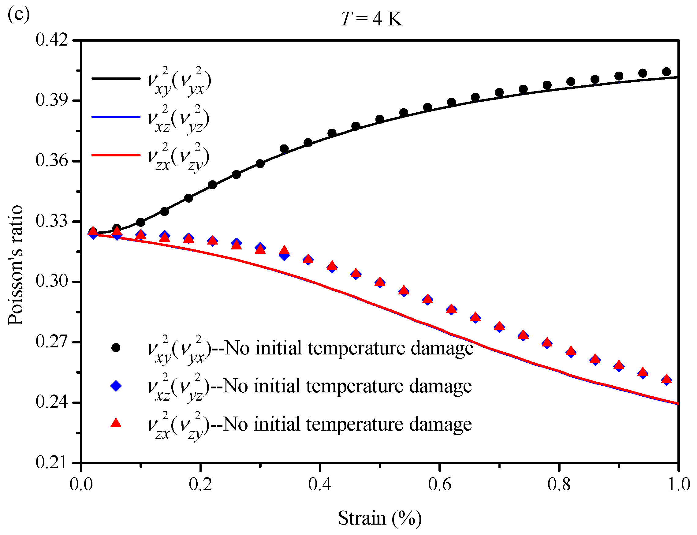
3.2. The Effective Elastic–Plastic Parameter of the Level 2 Homogeneous Superconducting Region
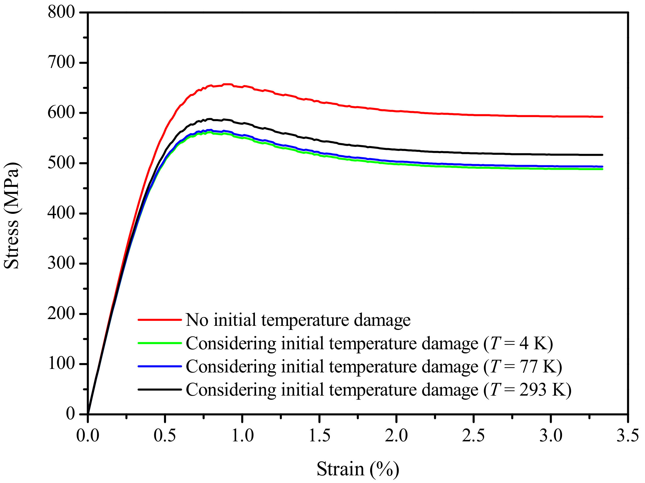
3.3. Elastoplastic Numerical Analysis Results of the EAS-Nb3Sn Strand Considering Fiber Damage
4. Conclusions
Author Contributions
Funding
Institutional Review Board Statement
Informed Consent Statement
Data Availability Statement
Conflicts of Interest
References
- Cao, Y.; Fatemi, V.; Fang, S.; Watanabe, K.; Taniguchi, T.; Kaxiras, E.; Pablo, J. Unconventional superconductivity in magic-angle graphene superlattices. Nature 2018, 556, 43–50. [Google Scholar] [CrossRef] [PubMed]
- Pęczkowski, P.; Łuszczek, M.; Szostak, E.; Naveen, K.C.M.; Anna, K.; Łukasz, G. Superconductivity and appearance of negative magnetocaloric effect in Ba1–xKxBiO3 perovskites, doped by Y, La and Pr. Acta Mater. 2022, 222, 117437. [Google Scholar] [CrossRef]
- Kowalik, M.; Zalecki, R.; Woch, W.M.; Tokarz, W.; Gondek, Ł. Critical Currents of (Bi1−xPbx)2Sr2Ca2Cu3Oy(x = 0.2 and 0.4) Films Deposited on Silver Substrate by Sedimentation. J. Supercond. Nov. Magn. 2017, 30, 2387–2391. [Google Scholar] [CrossRef][Green Version]
- You, F.; Ji, L.; Wang, Z.; Xie, Q.L.; Yan, S.L. Fabrication of double-sided Tl2Ba2CaCu2O8 Superconducting thin films on large-area sapphire substrates. Supercond. Sci. Technol. 2010, 23, 065002. [Google Scholar] [CrossRef]
- Pęczkowski, P.; Zachariasz, P.; Jastrzębski, C.; Piętosa, J.; Drzymała, E.; Gondek, Ł. On the Superconductivity Suppression in Eu1−xPrxBa2Cu3O7−δ. Materials 2021, 14, 3503. [Google Scholar] [CrossRef]
- Pęczkowski, P.; Kowalik, M.; Zachariasz, P.; Jastrzebski, C.; Jaegermann, Z.; Szterner, P.; Woch, W.M.; Szczytko, J. Synthesis and Physicochemical Properties of Nd-, Sm-, Eu-Based Cuprate High-Temperature Superconductors. Phys. Status Solidi A 2018, 215, 1700888. [Google Scholar] [CrossRef]
- Pęczkowski, P.; Szterner, P.; Jaegermann, Z.; Kowalik, M.; Zalecki, R.; Woch, W.M. Effects of Forming Pressure on Physicochemical Properties of YBCO Ceramics. J. Supercond. Nov. Magn. 2018, 31, 2719–2732. [Google Scholar] [CrossRef]
- Arbelaez, D.; Godeke, A.; Prestemon, S.O. An improved model for the strain dependence of the superconducting properties of Nb3Sn. Supercond. Sci. Technol. 2008, 22, 025005. [Google Scholar] [CrossRef][Green Version]
- Mitchell, N. The ITER Magnets: Design and Construction Status. IEEE Trans. Appl. Supercond. 2012, 22, 4200809. [Google Scholar] [CrossRef]
- Abelev, B.; Abramyan, A.; Adam, J.; Adamov´a, D.; Zyzak, M. Performance of the ALICE Experiment at the CERN LHC. Int. J. Mod. Phys. A 2014, 29, 1430044. [Google Scholar]
- Mitchell, N. Finite element simulations of elasto-plastic processes in Nb3Sn strands. Cryogenics 2005, 45, 501–515. [Google Scholar] [CrossRef]
- Wang, X.; Li, Y.; Gao, Y. Mechanical behaviors of multi-filament twist superconducting strand under tensile and cyclic loading. Cryogenics 2016, 73, 14–24. [Google Scholar] [CrossRef]
- Awaji, S.; Watanabe, K.; Katagiri, K. Improvement of mechanical and superconducting properties in CuNb/(Nb, Ti)3Sn wires by applying bending strain at room temperature. Supercond. Sci. Technol. 2003, 16, 733. [Google Scholar] [CrossRef]
- Chiesa, L.; Takayasu, M.; Minervini, J.V.; Gung, C.; Michael, P.C.; Fishman, V.; Titus, P.H. Experimental Studies of Transverse Stress Effects on the Critical Current of a Sub-Sized Nb3Sn Superconducting Cable. IEEE Trans. Appl. Supercond. 2007, 17, 1386–1389. [Google Scholar] [CrossRef]
- Eijnden, N.C.V.D.; Nijhuis, A.; Ilyin, Y.; Wessel, W.A.J.; Kate, H. Axial tensile stress–strain characterization of ITER model coil type Nb3Sn strands in TARSIS. Supercond. Sci. Technol. 2005, 18, 1523. [Google Scholar] [CrossRef]
- Ilyin, Y.; Nijhuis, A.; Wessel, W.A.J.; Van Den Eijnden, N.; Kate, H. Axial Tensile Stress-Strain Characterization of a 36 Nb3Sn Strands Cable. IEEE Trans. Appl. Supercond. 2006, 16, 1249–1252. [Google Scholar] [CrossRef]
- Nijhuis, A.; Pompe van Meerdervoort, R.P.; Krooshoop, H.J.G.; Wessel, W.A.J.; Zhou, C.; Rolando, G.; Mitchell, N.; Sanabria, C.; Lee, P.J.; Larbalestier, D.C. The effect of axial and transverse loading on the transport properties of ITER Nb3Sn strands. Supercond. Sci. Technol. 2013, 26, 084004. [Google Scholar] [CrossRef]
- Osamura, K.; Machiya, S.; Tsuchiya, Y.; Suzuki, H.; Shobu, T. Local strain and its influence on mechanical-electromagnetic properties of twisted and untwisted ITER Nb3Sn strands. Supercond. Sci. Technol. 2012, 25, 54010–54018. [Google Scholar] [CrossRef]
- Muzzi, L.; Corato, V.; Corte, A.D.; De Marzi, G.; Spina, T.; Daniels, J.; Michiel, M.D.; Buta, F.; Mondonico, G.; Seeber, B. Direct observation of Nb3Sn lattice deformation by high-energy x-ray diffraction in internal-tin wires subject to mechanical loads at 4.2 K. Kew Bull. 2012, 13, 54006–54013(8). [Google Scholar] [CrossRef]
- Scheuerlein, C.; Di Michiel, M.; Buta, F.; Seeber, B.; Senatore, C.; Flükiger, R.; Siegrist, T.; Besara, T.; Kadar, J.; Bordini, B.; et al. Stress distribution and lattice distortions in Nb3Sn multifilament wires under uniaxial tensile loading at 4.2 K. Supercond. Sci. Technol. 2015, 27, 98–102. [Google Scholar] [CrossRef]
- Vasil’ev, A.L.; Ballarino, A.; Bottura, L.; Gavrilkin, S.Y.; Degtyarenko, P.N.; Karateev, I.A.; Kruglov, V.S.; Latushkin, S.T.; Lunev, A.V.; Ryazanov, A.I. On the possible separation of the phase enriched with Nb in superconducting intermetallic Nb3Sn irradiated with fast protons. Bull. Lebedev Phys. Inst. 2017, 44, 118–121. [Google Scholar] [CrossRef]
- Pompili, F.; Esposito, B.; Marocco, D.; Podda, S.; Riva, M.; Baccaro, S.; Cemmi, A.; DiSarcina, I.; Quintieri, L.; Bocianc, D.; et al. Radiation and thermal stress test on diamond detectors for the Radial Neutron Camera of ITER. Nucl. Instrum. Methods Phys. Res. 2018, 936, 62–64. [Google Scholar] [CrossRef]
- Caiffi, B.; Angelone, M.; Colangeli, A.; Flammini, D.; Fonnesu, N.; Luìs, R.; Mariano, G.; Marocco, D.; Moro, F.; Tardocchic, M.; et al. Neutronic analyses in support of the conceptual design of the DTT tokamak radial neutron camera. Fusion Eng. Des. 2020, 157, 111629. [Google Scholar] [CrossRef]
- Jardin, A.; Bielecki, J.; Mazon, D.; Dankowski, J.; Kro, K.; Peysson, Y.; Scholz, M. Synthetic X-ray Tomography Diagnostics for Tokamak Plasmas. J. Fusion Energy 2020, 8, 240–250. [Google Scholar] [CrossRef]
- Vondracek, P.; Panek, R.; Hron, M.; Havlicek, J.; Zhang, H. Preliminary design of the COMPASS upgrade tokamak. Fusion Eng. Des. 2021, 169, 112490. [Google Scholar]
- Tan, W.; Ma, R.; Pan, H.; Zhao, H.; He, X.; Chen, X.; Zhao, C.; Lu, X. The observation of tin islands in Nb3Sn thin films deposited by magnetron sputtering. Phys. C 2020, 576, 1353667. [Google Scholar] [CrossRef]
- Zhang, H.; Huang, C.; Huang, R.; Li, L. A comparative study of compositions and microstructures of two types internal-tin process Nb3Sn wires. Cryogenics 2020, 110, 103145. [Google Scholar] [CrossRef]
- Xiao, L.; Lu, X.; Yang, Z.; Tan, W.; Xie, D. Annealing study on the properties of Cu-based Nb3Sn films under argon pressures for SRF applications. Phys. C 2021, 586, 1353894. [Google Scholar] [CrossRef]
- Boso, D.P.; Lefik, M.; Schrefler, B.A. A multilevel homogenised model for superconducting strand thermomechanics. Cryogenics 2005, 45, 259–271. [Google Scholar] [CrossRef]
- Boso, D.P.; Lefik, M.; Schrefler, B.A. Homogenisation methods for the thermo-mechanical analysis of Nb3Sn strand. Cryogenics. 2006, 46, 569–580. [Google Scholar] [CrossRef]
- Boso, D.P.; Lefik, M.; Schrefler, B.A. Multiscale analysis of the influence of the triplet helicoidal geometry on the strain state of a Nb3Sn based strand for ITER coils. Cryogenics 2005, 45, 589–605. [Google Scholar] [CrossRef]
- Boso, D.P. A simple and effective approach for thermo-mechanical modelling of composite superconducting wires. Supercond. Sci. Technol. 2013, 26, 045006. [Google Scholar] [CrossRef]
- Ahoranta, M.; Lehtonen, J.; Tarhasaari, T.; Wiess, K. Modelling of local strain and stress relaxation in bronze processed Nb3Sn wires. Supercond. Ence Technol. 2008, 21, 025005. [Google Scholar] [CrossRef]
- Collins, B.; Krishnan, J.; Arbelaez, D.; Ferracin, P.; PrestemonS, O.; Godeke, A.; Dietderich, D.R.; Zohdi, T. Introduction of Nonlinear Properties into Hierachical Models of Nb3Sn Strands. IEEE Trans. Appl. Supercond. 2011, 21, 2320–2323. [Google Scholar] [CrossRef]
- Collins, B.; Krishnan, J.; Arbelaez, D.; Ferracin, P.; Dietderich, D.R.; Zohdi, T.I. Computation of Strain State in a Strand Using Nonlinear Hierarchical Models. IEEE Trans. Appl. Supercond. 2012, 22, 4905104. [Google Scholar] [CrossRef]
- Jing, Z.; Yong, H.; Zhou, Y. Theoretical Modeling for the Effect of Twisting on the Properties of Multi-filamentary Superconducting Strand. IEEE Trans. Appl. Supercond. 2013, 23, 6000307. [Google Scholar] [CrossRef]
- Liu, B.; Jing, Z.; Yong, H.; Zhou, Y.H. Strain distributions in superconducting strands with twisted filaments. Compos. Struct. 2017, 174, 158–165. [Google Scholar] [CrossRef]
- Wang, W.; Qin, J.; Yu, M.; Li, J. Heat transfer analysis during heat treatment of Nb3Sn coils for the CFETR CSMC. Fusion Eng. Des. 2021, 165, 112248. [Google Scholar] [CrossRef]
- Wang, Q.Y.; Xue, C.; Chen, Y.Q.; Ou, X.J.; Wu, W.; Liu, W.; Ma, P.; Sun, L.T.; Zhao, H.W.; Zhou, Y.H. Thermomagnetic instabilities of Nb3Sn wires inside the superconducting solenoid. Phys. C 2021, 593, 1354002. [Google Scholar] [CrossRef]
- Xu, X.; Sumption, M.D.; Lee, J.; Rochester, J.; Peng, X. Persistent compositions of non-stoichiometric compounds with low bulk diffusivity: A theory and application to Nb3Sn superconductors. J. Alloy. Compd. 2020, 845, 156182. [Google Scholar] [CrossRef]
- Curtin, W.A. Theory of Mechanical Properties of Ceramic-Matrix Composites. J. Am. Ceram. Soc. 1991, 74, 2837–2845. [Google Scholar] [CrossRef]
- Curtin, W.A.; Zhou, S.J. Influence of processing damage on performance of fiber-reinforced composites. J. Mech. Phys. Solids 1995, 43, 343–363. [Google Scholar] [CrossRef]
- Luo, W.; Zheng, X.J. Initial damage influence of stiffness reduction for bronze route Nb3Sn strands. Phys. C 2011, 471, 558–562. [Google Scholar] [CrossRef]
- Yong, H.D.; Yang, P.L.; Xue, C.; Zhou, Y.H. Fractue behavior of filament in Nb3Sn strands with crack-bridging model. Fusion Eng. Des. 2016, 102, 66–73. [Google Scholar] [CrossRef]
- Popova, E.N.; Popov, V.V. Dislocation and grain structure formation in Nb filaments of different geometry at fabrication of Nb3Sn-based superconducting wires. Mater. Charact. 2020, 167, 110488. [Google Scholar] [CrossRef]
- Abdyukhanov, I.M.; Tsapleva, A.S.; Mareev, K.A.; Alekseev, M.V.; Luk'yanov, P.A.; Polikarpova, M.V.; Zakharova, G.A.; Panashchuk, I.A.; Nasibulin, M.N.; Dergunova, E.A. Investigation of Local Damage Effect on Nb3Sn Superconductor Properties. At. Energy 2021, 128, 343–348. [Google Scholar] [CrossRef]
- Kaverin, D.; Potanina, L.; Shutov, K.; Vysotsky, V.; Tronza, V.; Mitin, A.; Abdyukhanov, I.; Alekseev, M. Analysis of Nb3Sn Strand Microstructure After Full-size SULTAN Test of ITER TF Conductor Sample. Phys. Procedia 2015, 67, 914–919. [Google Scholar] [CrossRef][Green Version]
- Shen, F.; Zhang, H.; Huang, C.; Li, L. Experimental study on strain sensitivity of Internal-Tin Nb3Sn superconducting strand based on non-destructive technology. Phys. C 2021, 584, 1353784. [Google Scholar] [CrossRef]


| Copper | Tantalum | Nb3Sn | Bronze | |
|---|---|---|---|---|
| Volume fraction | 0.600 | 0.040 | 0.148 | 0.212 |
| 1.18 × 10⁵ | 5.70 × 10⁴ | 5.24 × 10⁴ | 0 | 0 | 0 |
| 5.70 × 10⁴ | 1.18 × 10⁵ | 5.24 × 10⁴ | 0 | 0 | 0 |
| 5.24 × 10⁴ | 5.24 × 10⁴ | 1.20 × 10⁵ | 0 | 0 | 0 |
| 0 | 0 | 0 | 3.34 × 10⁴ | 0 | 0 |
| 0 | 0 | 0 | 0 | 3.08 × 10⁴ | 0 |
| 0 | 0 | 0 | 0 | 0 | 3.08 × 10⁴ |
| 1.09 × 10⁵ | 5.34 × 10⁴ | 5.00 × 10⁴ | 0 | 0 | 0 |
| 5.34 × 10⁴ | 1.09 × 10⁵ | 5.00 × 10⁴ | 0 | 0 | 0 |
| 5.00 × 10⁴ | 5.00 × 10⁴ | 1.12 × 10⁵ | 0 | 0 | 0 |
| 0 | 0 | 0 | 2.98 × 10⁴ | 0 | 0 |
| 0 | 0 | 0 | 0 | 2.81 × 10⁴ | 0 |
| 0 | 0 | 0 | 0 | 0 | 2.81 × 10⁴ |
Publisher’s Note: MDPI stays neutral with regard to jurisdictional claims in published maps and institutional affiliations. |
© 2022 by the authors. Licensee MDPI, Basel, Switzerland. This article is an open access article distributed under the terms and conditions of the Creative Commons Attribution (CC BY) license (https://creativecommons.org/licenses/by/4.0/).
Share and Cite
Zhang, Z.; Shi, L. Elastic–Plastic Mechanical Behavior Analysis of a Nb3Sn Superconducting Strand with Initial Thermal Damage. Appl. Sci. 2022, 12, 8313. https://doi.org/10.3390/app12168313
Zhang Z, Shi L. Elastic–Plastic Mechanical Behavior Analysis of a Nb3Sn Superconducting Strand with Initial Thermal Damage. Applied Sciences. 2022; 12(16):8313. https://doi.org/10.3390/app12168313
Chicago/Turabian StyleZhang, Zhichao, and Lifan Shi. 2022. "Elastic–Plastic Mechanical Behavior Analysis of a Nb3Sn Superconducting Strand with Initial Thermal Damage" Applied Sciences 12, no. 16: 8313. https://doi.org/10.3390/app12168313
APA StyleZhang, Z., & Shi, L. (2022). Elastic–Plastic Mechanical Behavior Analysis of a Nb3Sn Superconducting Strand with Initial Thermal Damage. Applied Sciences, 12(16), 8313. https://doi.org/10.3390/app12168313