Article

Analysis of the State of Building Conservation through Study of Damage and Its Evolution with the State of Conservation Assessment BIM Model (SCABIM)

Department of Architecture, University of the Basque Country UPV/EHU, Plaza Oñati 2, 20018 Donostia-San Sebastián, Spain
*
Authors to whom correspondence should be addressed.
Appl. Sci. 2022, 12(14), 7259; https://doi.org/10.3390/app12147259
Submission received: 21 June 2022 / Revised: 13 July 2022 / Accepted: 18 July 2022 / Published: 19 July 2022

Abstract

:
Residential building inspections are periodically required by public authorities. However, current approaches to storing and viewing data concerning an inspection are often collected in reports whose form and limited content hamper the rigorous assessment of the building’s state of conservation and subsequent repair of the identified damage and alterations. This research proposes a method for documenting and displaying inspection-related information in BIM models to generate a dynamic information model. Damage is spatially located by means of a parametric family, which collects the necessary information about each instance of damage and enables agile and up-to-date information extraction. The proposed method was validated in a residential building situated in San Sebastián, with a scenario designed to demonstrate its ability to support the diagnosis of causes and decision making regarding maintenance. This work demonstrates the advantages of the parametric representation of information on damage and alterations in a BIM model, which facilitates the management of a residential building’s life cycle by means of a digital twin of the building. The results shown in this research may be very interesting for researchers as well as for those whose work involves the rehabilitation of residential buildings.

1. Introduction

According to Bruntland [1], sustainable development is that which responds to present needs without compromising the ability of future generations to meet their own needs. To that end, the decisions made in the planning, design, construction, operation and maintenance phases [2] of buildings should be oriented toward sustainability. This concept of sustainability can also be successfully applied in rehabilitation projects, not just because it is profitable in the long term but also because it can reduce operating costs (energy and/or water consumption) and environmental impact (CO2 emissions) while ensuring the building’s resilience after rehabilitation [3,4].
Over the last 20 years, the construction sector productivity has increased by an average of 1%, compared to 2.8% for the economy as a whole or the 3.6% for the manufacturing sector. This can be partly explained by the low level of digitalisation. Several EU reports identify systemic problems in the construction sector related to low levels of collaboration, low investment in R&D and Innovation technologies and poor information management.
From a canonical standpoint, a building’s life cycle encompasses the vision of a building throughout its existence, not just in its operative phase but also including the design, construction, performance, dismantling and waste treatment [5]. A building’s life cycle hence covers an ample circle of time in which a large volume of data is generated. Besides its abundance, the disparate nature of the information collected makes it hard to manage and hampers the ability to benefit from it. In this regard, the building information modelling (BIM) methodology is a tool that enables the integrated development of projects, which can be a decisive advantage on the road to efficient management. BIM can be used to manage a building’s entire life cycle [6,7,8,9], enabling an agile and effective exchange of information. However, the application of this new technology has not gained much of a footing in the management of existing buildings [10], although there are initiatives and projects that have begun to take the first steps [11,12,13,14]. Indeed, in actions to rehabilitate already constructed buildings that use the traditional methodology, relatively inefficient procedures exist due to a lack of cohesion of existing information regarding the intended object of intervention. Furthermore, the various agents taking part in this process work separately, following unconnected protocols, which favours information dispersal [15]. There are international policies which highlight the need for collaborative systems that allow such information to be exchanged [16,17,18]. In these cases, it is indispensable to link the existing object (existing building geometry) to the respective non-geometric information: technical reports, information about materials and systems or construction solutions and the respective state of conservation, among other information [19,20]. This allows a thorough examination of the building to be carried out so that the correct action can be taken for rehabilitation and conservation.
Moreover, the conservation of building stock is indisputably linked to the regular maintenance of buildings, with conservation defined as being a real need in daily practice. Activities associated with building maintenance account for more than 85% of the overall costs of a building’s life cycle [21]. Maintenance includes activities undertaken by specialised personnel to ensure that the building still fulfils its intended functions or those added to comply with new stricter, or more demanding regulations [22]. Seeley [23] defines maintenance as “the work undertaken to keep, restore or improve every part of a building, its services and its surrounds, to a currently acceptable standard and to sustain the utility and value of the building”. In this regard, public administrations have regulated a control system for residential buildings to verify the conservation and rehabilitation of the property. Although the implementation of such inspections varies from one territory to another, the bases are the same in virtually every country [24]. In the case of Spain, a periodic visual technical inspection called the Building Technical Inspection (ITE—Inspección Técnica del Edificio) is carried out by specialised technical personnel (architects and technical architects) who draw up a report on the state of conservation of the building’s common elements, determining maintenance actions that should be completed as well as their degree of urgency, to ensure the safety of the building as well as its inhabitants.
In this context, BIM technology can be a good tool for managing a building’s entire life cycle [25] and especially its maintenance, with a view to extending its useful life [26,27,28]. However, the BIM has yet to develop specific methodologies for including in the digital model the damage and alterations detected and assessing the building’s state of conservation. Maintenance information linked to the BIM model improves the quality and precision of the building’s operating systems [29]. The information stored in a digital twin covers all parts of the building and serves to create the database needed for continuous maintenance [30,31]. Proper upkeep will improve a building’s performance and reduce repairs and respective maintenance costs [32]. The aim has thus been to achieve a ‘smart building’ that integrates the building’s main systems in a single model included in a common environment that allows information and functions to be shared among different agents in order to improve the building’s operations. The creation of an accurate inventory of construction systems, materials and damage existing in the building, concentrated in a database linked to the three-dimensional model, allows that data to be processed and analysed in an agile manner when decisions must be made. In this context, the BIM methodology is an excellent tool for carrying out rehabilitation interventions meant to achieve a more efficient building [33].
The aim of this work is to structure and design a BIM dynamic model (a model in which information can be added and updated during the building’s life cycle) to record all the useful information on the state of conservation of a residential building, to optimise its conservation and maintenance, in turn enabling agile and up-to-date viewing and extraction of information about its conservation [34].
An analysis of the traditional procedures served to identify their problems; the BIM methodology regarding a building’s state of conservation (SCABIM) was therefore designed to streamline this process. The proposed methodology was applied and validated in a case study of a tall residential building in Spain. The results showed that in the traditional process for assessing the building’s state of conservation, the information is not connected (original building plans [35,36,37], previous reports, energy certificates, etc., are in documents without any link), and the location of any damage analysed and/or repaired is not known. This hinders their accurate analysis. The reports generated do not depict the damage’s severity; on some occasions, action is not taken with the necessary urgency and situations of risk arise. They present a snapshot of the building’s state of conservation and do not monitor damage, its evolution and the building’s state of conservation in general.
The proposed SCABIM methodology, however, responds to the identified problems by using a digital twin of the studied building. The information is linked to a dynamic model with the locations of damage. That information is continually updated, providing a picture of the building’s state of conservation. The diagnosis of damage could thus be adjusted and, depending on the urgency of intervention, proposals for action can be prioritised and optimised.

2. Materials and Methods

This section defines the context in which the research project has been developed. On the one hand, it explains the analogic procedure to generate the state of conservation report required currently by the Spanish public administration. On the other hand, it describes the design and structure of the SCABIM methodology proposed to optimise the assessment process in order to achieve a more efficient management of the conservation and maintenance tasks.

2.1. Context of the Research Project

The research project titled “BIM Technology for Optimized Management of Cultural and Architectural Heritage” enabled, among other aspects, the development of a workflow to combine in a single model accessible by all agents the existing alterations and pathologies in a building so they could be viewed in an agile and intuitive manner, facilitating decision making during the phase of proposals for action to correct them. This university–enterprise–society research project involved the company Kursaal Rehabilitaciones S.A. The research accordingly focused on the typology of work of the company, which specialises in the rehabilitation of façades of tall residential buildings. It used an innovative methodology for analysing, processing and managing information based on a 3D geometric model with an integrated specialised database. The information needed to streamline the building’s management throughout its life cycle is extracted via a filter from this information model.
The work was limited to façade rehabilitation interventions, with the SATE (exterior thermal insulation system) as well as ventilated façade solutions meant to improve energy efficiency, as this was the collaborating company’s most habitual type of work. The research was based on the compilation of existing information with respect to the selected pilot case: original plan, technical reports, ITEs, energy certificates and intervention projects, etc. The BIM workflow was established, identifying all processes (data acquisition, modelling of the building as built, with existing pathological processes and alterations), material resources, necessary software and hardware, documentation generated and respective processing, besides identifying the modelling phases, roles and intervening agents and deliverables, among others.

2.2. Technical Inspection of the Building

To undertake the rehabilitation of a building, it is essential to thoroughly examine it. The building should be geo-located and environmental conditioners that may cause the alterations affecting it should be analysed; its year of construction should be known, and the building systems and materials used identified; any rehabilitation actions in previous phases should be analysed and the alterations and pathological processes affecting the building with respect to both common elements and private areas identified. Examination of the ‘patient’, with all respective conditioners, will be used to produce a dictum (judgement on the state of conservation of the building provided by a specialised technician) about the general state of the building’s conservation along with a reasonable diagnosis of each detected instance of damage in order to prioritise repairs that have to be carried out [38].
In this regard, Spanish administrations have enacted specific regulations that govern technical inspections of predominantly residential buildings [39]. These inspections are used to assess the buildings’ state of conservation. Those built 50 or more years ago must submit a report to the authorities every ten years. A building’s technical inspection comprises a visual inspection of the roof, foundations, structure, façades and common networks for supply and removal of water in order to know the respective construction characteristics, state of conservation and pathologies that may affect the building. Among others, the goals of technical inspection of buildings are to: (a) identify damage and deterioration visually detected during the inspection, resulting from exterior or interior causes, defects or lack of maintenance; (b) make a preliminary diagnosis of possible causes of the observed pathologies and of the buildings’ state of conservation; (c) classify by order of severity the problems detected and how they interrelate; and (d) assess the significance of damage and rule on the need for intervention, and recommend the appropriate type of intervention.
The public administration that requires and controls the technical inspection of buildings provides free software, ITE-PV-v3, as a support tool for producing a report on a building’s state of conservation. After visual inspection of the building, all the information is entered into the software tool; once all the sections have been filled out, a doc file is automatically exported in a report with a set format. Moreover, for the report to be registered [40] in the administration, the software exports a folder of xml files.
The inspection process develops in three stages: data collection, report and dictum. Figure 1 depicts the workflow comprising the three stages.
The parameters for the state of conservation, severity of damage and assessment of intervention are determined using a dropdown menu providing various options with specific terminology. These already established parameters are shown in Table 1.
Some free-text parameters are also defined: description of symptoms, determination of possible causes and a parameter for observations. This information is complemented by photographs which graphically record the state of conservation of the inspected elements.

2.3. The Design and Structure of the SCABIM Model

In order to design and structure the SCABIM model, it is essential that the agents involved in the building condition assessment process (maintenance technician and the BIM team) interact using a cooperative and collaborative methodology by means of their own server via VPN and real-time synchronisation platforms in the cloud.
Before beginning to prepare the BIM model of the building’s state of conservation, a contract document was drawn up, including the BEP (BIM execution plan) [41,42], which sets out general information about the building, the roles and responsibilities of the BIM work team; the goals and uses of the BIM; the LOD (level of development) [43,44] of each model and the nomenclature of generated files; and the strategies for document control and organisation of the models along with the resources.
A thorough examination of a building requires a graphic survey prior to its current state, endowed with a sufficient degree of accuracy to precisely determine the geometric configuration of the structure as well as the particular changes that users have gradually introduced over time [45]. At present, the combined use of digital techniques for geometric data collection by means of a topographic survey with total station, terrestrial laser scanner and short-range photogrammetry assisted by RPAS (remotely piloted aircraft system) is the most effective procedure for conducting a high-precision geo-referenced architectural survey. Total station control points can be determined for geo-referencing and metric verification of data. The terrestrial laser scanner can capture geometric data at a long distance with very high accuracy. Short-range photogrammetry assisted by RPAS facilitates the capture of data in areas that are hidden or hard to access beyond the reach of a laser scanner. The architectural survey accomplished using these techniques is thus a three-dimensional digital twin of the captured data [46].
Information should be classified in several federated models. Taking into account the aspects that are analysed in the state of conservation assessment, four models are generated: the Datum model to link the general information and the collected previous information about the building, the architectural model, the structural model and the MEP model. This set of models is exportable in an open source file (IFC; Industry Foundation Classes) to perform the quality control of these models. The revised model set is prepared to insert the building conservation status parameters defined in the ITE. These parameters allow the addition of damage and alteration data (input) to the model or set of models through a family designed for this purpose. Once the model has been fed with this data, view templates, filters and planning tables are generated to extract the information on the state of conservation of the building (output) in a visual and agile way. This SCABIM model is a dynamic model as it allows both input and output of information regarding the state of conservation of the building during the rest of the building’s life cycle. The proposal’s process is depicted in Figure 2.

3. Case Study

The designed and structured SCABIM methodology has been applied to a case study in a high-rise residential building. The results have been compared with those obtained in the state of preservation report carried out without BIM.

3.1. Examination of the Building

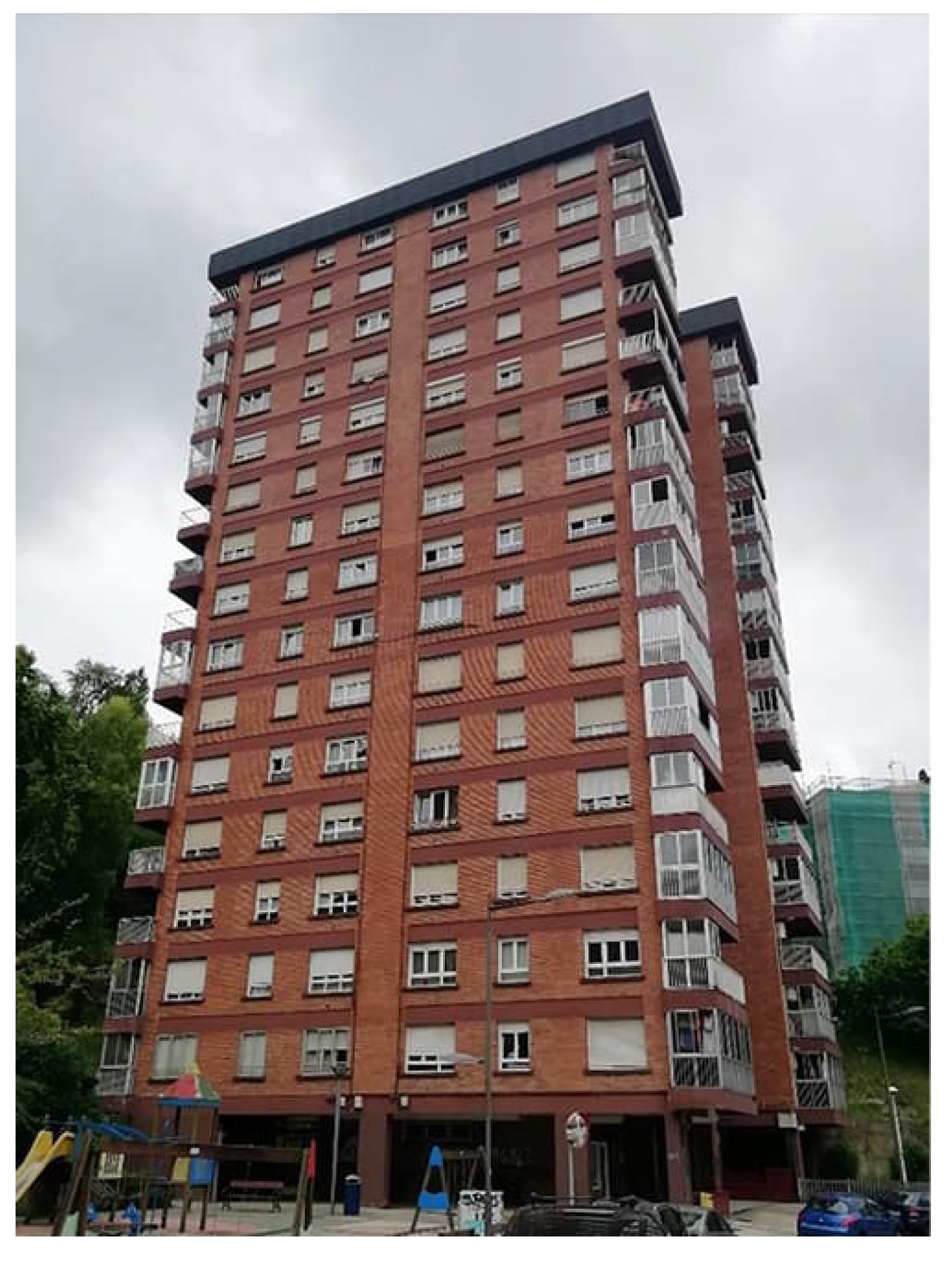
The selected case is situated at Calle Bertsolari Txirrita, 38, in San Sebastián, Spain. It is a tall residential building with 90 homes built in 1972 and consists of a ground floor and 15 upper floors with a rectangular floor plan, from which four bodies stand out, forming a double T. It also has a basement which occupies the same area as the block. The ground floor is mostly open, forming a perimeter porch, in the centre of which is the entrance doorway providing access to three options: the stairway to the basement, the stairway to the residences and the two lifts. The building is shown in Figure 3.
It was built with a reinforced concrete structure comprising porticos on large pillars with one-way joist-and-block floor slabs. The façades were built in staggered facing brick, with an interior wall of hollow brick forming an unventilated air chamber. They did not originally have thermal insulation. The interior distribution was accomplished with ceramic partitions, including the separation between apartments and between them and the common floor spaces. The top consists of a roof terrace with slight slopes for water drainage. Smoke removal, as well as ventilation of kitchens and toilets, was achieved with ducts made of prefabricated concrete pieces, forming rectangular-section chimneys. The balconies were made of solid slab overhangs with the concrete slab fronts extending up to the façade wall, in contrast to the facing brick walls. The interior doors, as well as the windows and doors providing access to balconies, are in wood, with the latter integrating monolithic glass. The building plans are available in Appendix A.

3.2. Survey of the Existing Building

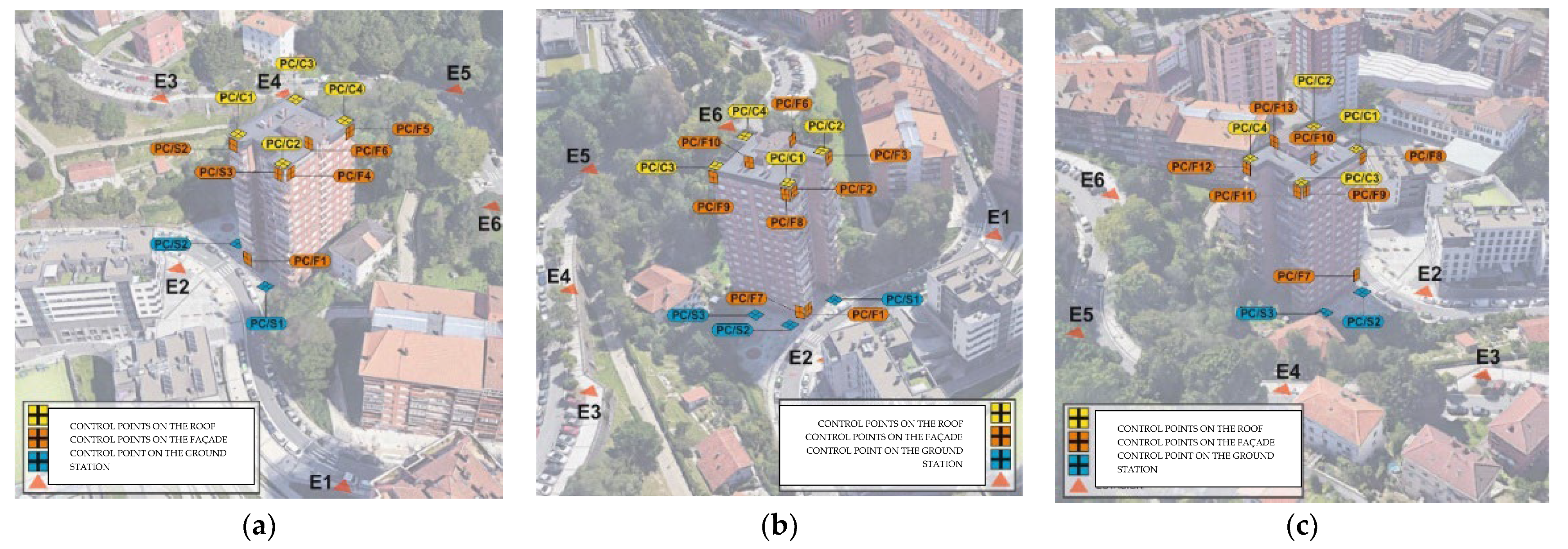
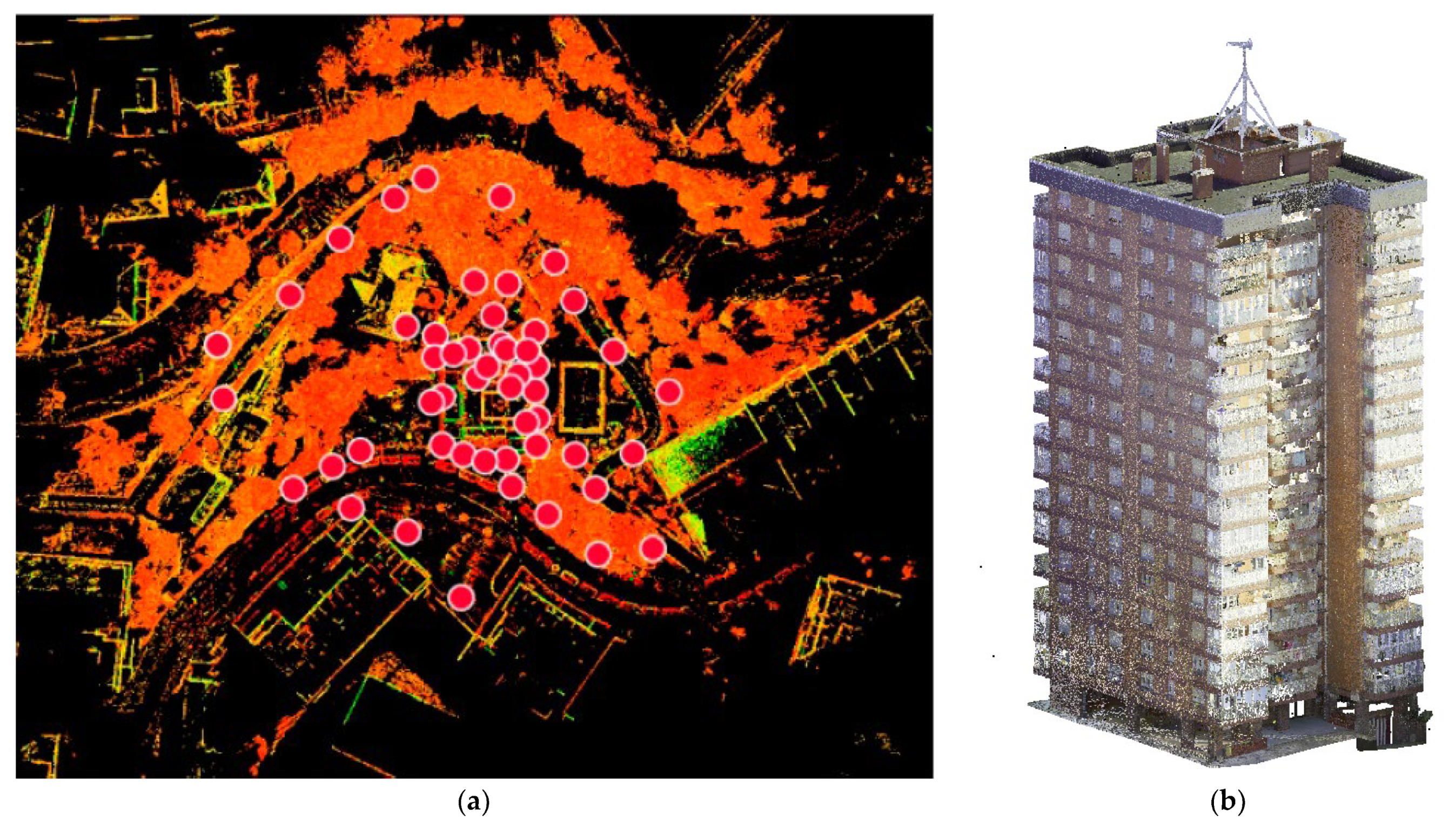
The survey of control points was carried out using total station and laser scanner. The main aim of the system of control points was to obtain a three-dimensional digital model of the geo-referenced survey in absolute UTM coordinates, located so they can be recorded by laser scanning. Figure 4 shows the control points determined for the building and its surroundings.
To survey the building, the exterior façades were scanned along with the tower’s roof. The survey covered the dimensions of the façades, balconies, window openings and visible installations. A Leica RTC 360 scanner was used. This massive data acquisition system provides very high geometric accuracy and is very useful in buildings with complex geometries or great heights. The scanning was completed with 360° panoramic images. The overlapping of the panoramic images on the point cloud made it possible to analyse the building off-site to visualise damages and make very precise measurements, avoiding the need for repeated visits to the building.
The clouds were recorded and geo-located in Leica’s Register software. A total of 52 stations were realised, with 83 links. The point cloud was processed by importing it in pts software to Recap; after processing, it was re-exported in rcp format so it could connect with the Revit model for modelling of the building’s current phase, linking all the information in this model so the respective state of conservation could be assessed. The location of the building’s scan points and the point cloud can be seen in Figure 5.

3.3. BIM Model of the Building’s State of Conservation

This section details the structure of the state of conservation BIM model in a case study and explains how to model a parametric family to locate damages. Finally, it sets out the viewing templates and planning tables to be used when assessing the state of conservation of the building.

3.3.1. Structure of the BIM and Definition of Parameters

The modelling software used in this case study is Autodesk’s Revit. The set of models prepared for analysis and assessment of the building’s state of conservation is the departure point of an information repository on the life cycle of an existing building with the respective periodic updates, which functions as a digital twin of the existing building.
This updated model enables the building’s state of conservation to be ascertained at all times and serves to support the drafting of plans and projects for the management and rehabilitation of the building. In this set of associated models, there is a ‘datum’ model for non-geometric information (original building plan, reports, energy studies, etc.) and three models covering (by field) the damage to architectural elements (envelope), structural damage and pathological processes detected in plumbing and sewerage installations, to locate damage affecting the four elements required by the specific regulations governing technical inspections of buildings: roof, façade, foundations and structure and the water supply and sewerage installations. Figure 6 depicts the three-dimensional model and the models that have been federated with the architectural model.
Five sets of parameters were also defined: general data, architectural data, another covering parameters to identify the state of conservation of the elements analysed, a set to assess the intervention needed for each instance of damage and finally, corrective measures. In the latter set, the start and end dates of the damage repair work are defined, another indicates whether or not the damage has been corrected, and the last parameter contains reference information on the intervention carried out. These parameters were defined in the initial contract documentation by means of a table that detailed the parameter’s name, description, hierarchy (project parameter, type or exemplar) and type of field (text, URL, dropdown menu, yes/no, etc.). These parameters are shown in Table 2.

3.3.2. Elements for Locating Damage and Inclusion of Shared and Project Parameters

One element was modelled to locate instances of damage in the model [47], starting with a generic model face-based family template. The geometry modelled has already been used in some examples contained in the book published by the Official College of Surveyors, Technical Architects and Building Engineers of Madrid, “BIM in Existing Buildings” [48]. The family generated to locate instances of damage can be seen in Figure 7.
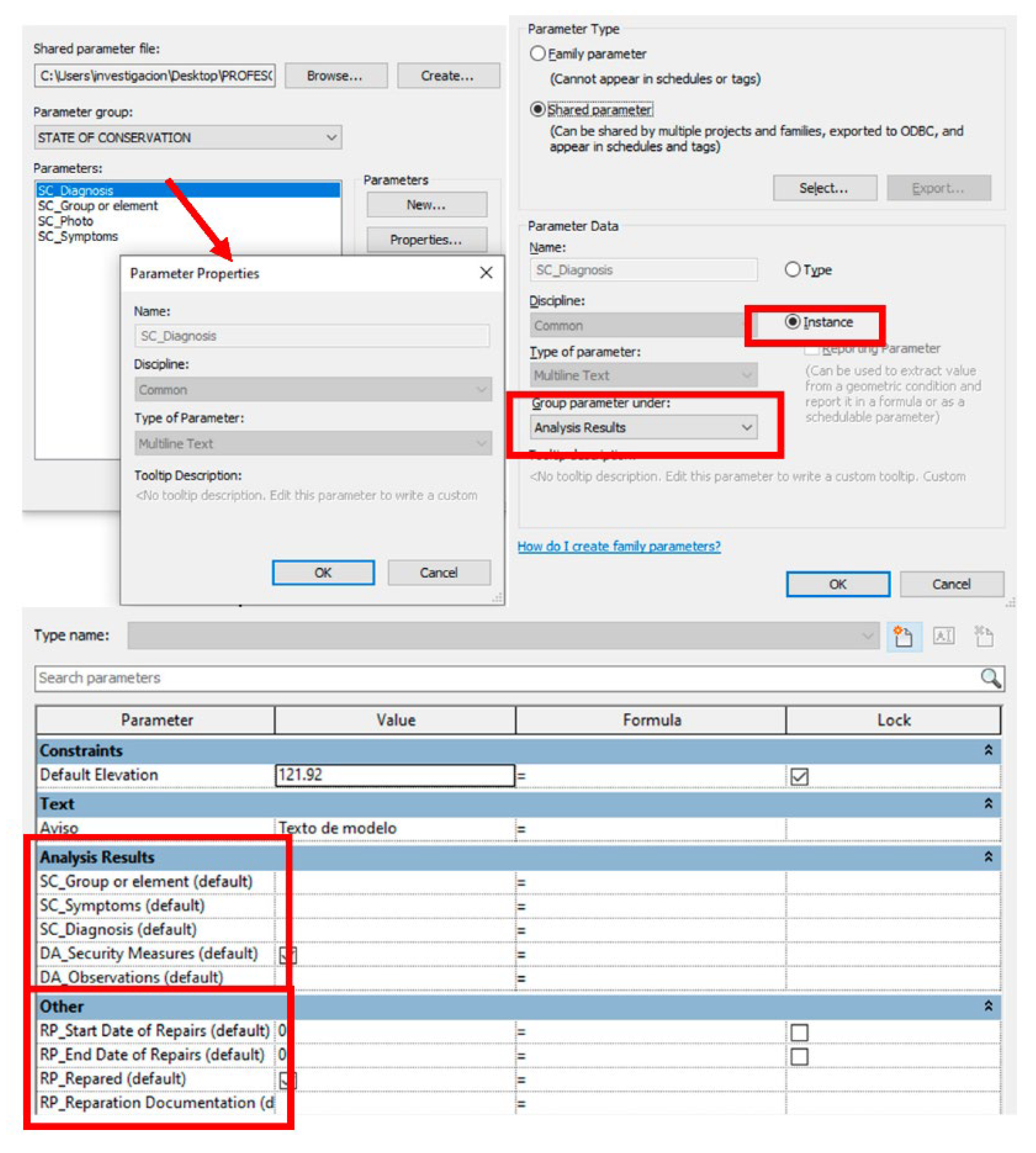
When editing the family, the shared and exemplar parameters were created, enabling the determination of conservation state of the analysed elements, assessment of the intervention and the dates regarding the repair work carried out. These are saved in a .txt file. Five groups or sets of defined parameters were generated in the documentation before modelling, and the shared parameters of each set were introduced. All the parameters vary depending on the damage; they were therefore entered as exemplar parameters and included in the family. The parameters for state of conservation and assessment of the intervention were grouped in Analysis Results, and the parameters referring to damage repair were included in Other. Figure 8 depicts the process for generating these parameters.
Among the parameters for assessing damage, one was defined to determine the need for safety measures. It is a parameter of the yes/no type. In the event that measures must be taken, a red crown becomes visible in the family to call attention to the model. To modify the visibility depending on the response marked for this parameter, the elements that comprise the crown were selected, and the visibility was modified from the properties window by activating the visible property and associating the ED Safety Measures family parameter.
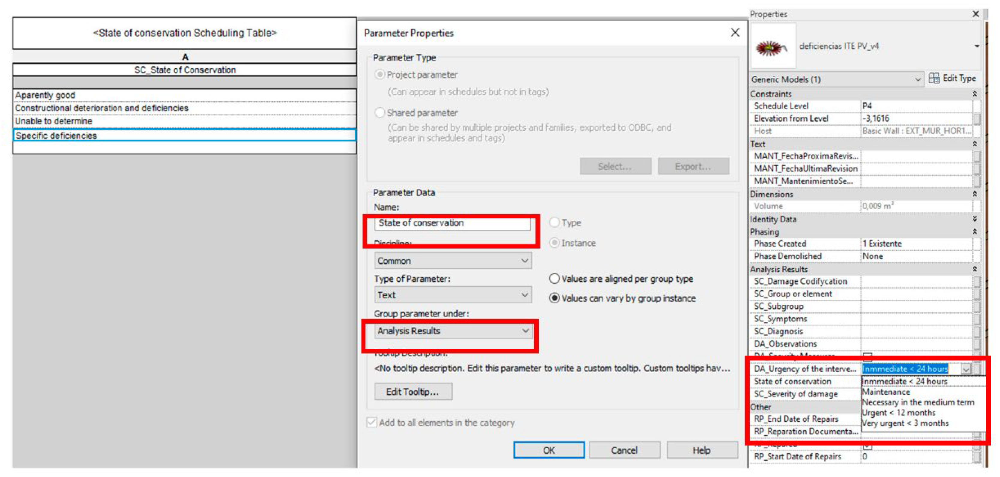
The parameters of the dropdown menu type, with the specific terminology defined in the ITE reports, were nevertheless not defined in the location of the warnings family. These are defined in the project itself through planning tables of the type ‘planning table keys for generic models’. These planning tables are designed for the parameters of SC_State of Conservation, SC_ Severity of damage and DA_Assessment. When defining the properties of the planning table, a new text-type parameter was generated and grouped so it could appear with the results of the analysis of the properties table. It is important to select the variable values option depending on the exemplar so that these parameters can be defined for each instance of damage. The data rows with keys for specific terminology were added to the table. Figure 9 depicts the creation of dropdown menu parameters using key-type planning tables.

3.3.3. Viewing Templates and Planning Tables for Assessment of the Building’s State of Conservation

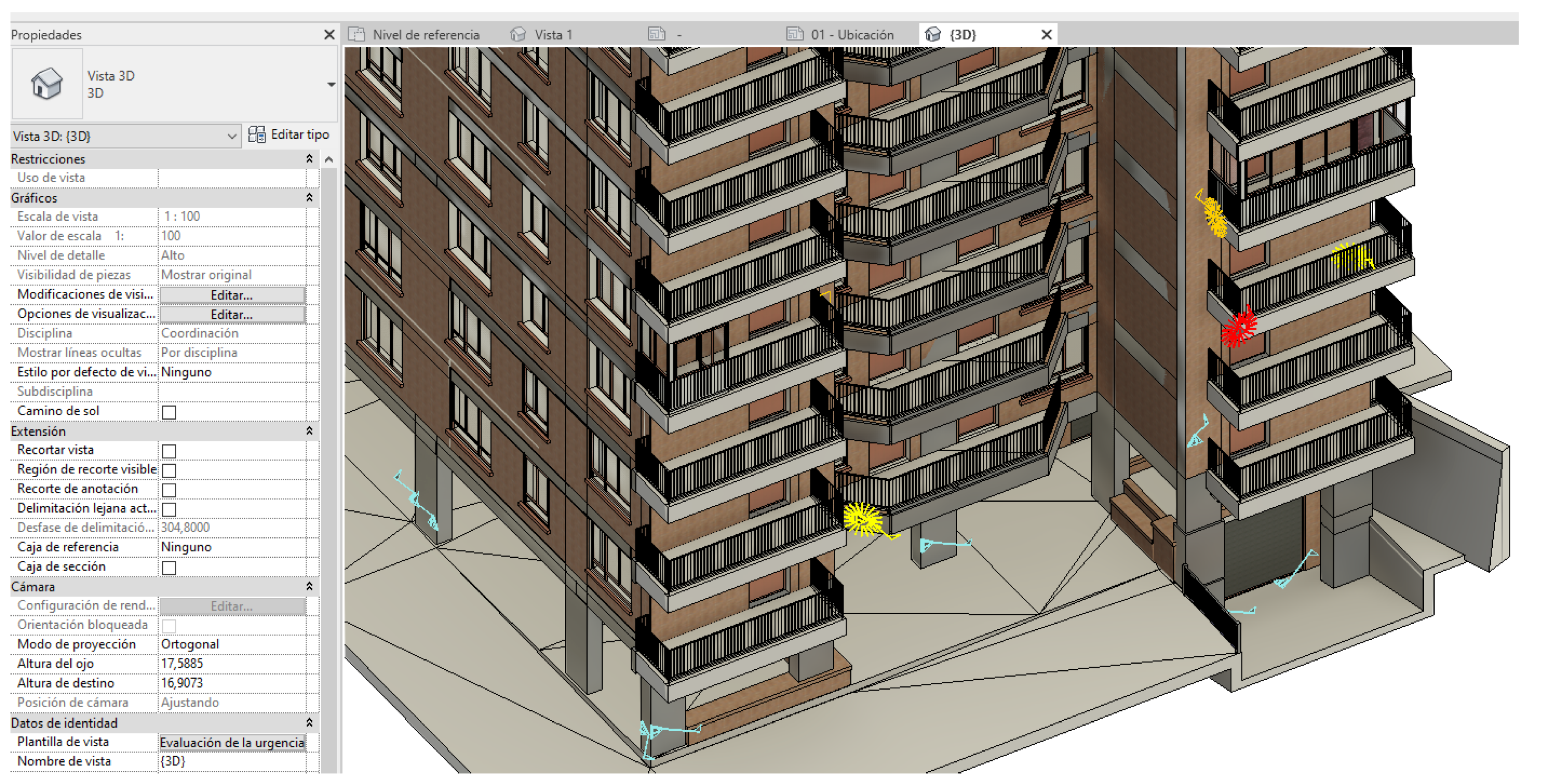
With the building modelled and the damage location family loaded into the model, the instances of damage were located and the data from the defined parameters added along with the image for each instance of damage. So that the model can be used to visualise the urgency of intervention regarding each instance of damage, a colour scale was established for the damage location family. This enables easy identification of the most severe damage and instances which require safety measures (activated crown). To ensure that the damage location family changes colour according to the urgency of intervention, a viewing template was generated, which, by modifying the graphics’ visibility, generated several filters. Figure 10 shows the filters to modify the visibility depending on the urgency of the intervention.
The parameters defined for each instance of damage enable the generation of different viewing templates, depending on the information we want to obtain. Visibility filters can be generated for that purpose. For example, a viewing template can be generated to see only the damage that requires safety measures; a viewing template to see instances of damage in the roofs group; another view for damage that has already been repaired or a view to see damage requiring immediate, urgent or very urgent intervention. Furthermore, planning tables were generated, which contain all the data on damage detected in the building, to thereby obtain a report on all such instances.

4. Results

This section presents the results obtained from the report on building conservation that public authorities have made a mandatory requirement, using ITE-PV-v3 software, and those obtained with the proposed SCABIM state of building conservation model. From the start of the process with the assessment of the building’s conservation state until the work is completed, a significant amount of information affecting the building’s life cycle is generated. The comparison of how this information is managed in each process demonstrated their respective problems and advantages.
In the case of the report on the building’s state of conservation [49], four fundamental problems were identified: the information generated since the report began to be drawn up and until damage repair is UNCONNECTED; the instances of damage identified are described generally and the respective LOCATION IN THE BUILDING IS NOT INDICATED (the report does not contain the building’s planimetrics with the location of damage or alterations); it is HARD TO IDENTIFY THE SEVERITY of damage that requires more urgent intervention; the information provided is a SNAPSHOT OF THE BUILDING’S STATE OF CONSERVATION at a specific time in its life cycle, and there is no updated information on repaired damage.
In the case under study, the report on the building’s state of conservation was written in 2015 at the owner’s request. The report includes initial and classificatory information about the building, with its location, compositional data, typology and degree of exposure, etc. The graphic information is limited to a site plan and a photo of the main façade. A series of files contain data on the construction of the elements analysed (roof, structure, façade and water supply and sewerage installations) and assess their state of conservation, describing the symptoms and complementing the information with a few photos. The significance of each instance of damage is determined, and the possible causes are indicated, along with an assessment regarding the urgency of intervention. After all the damage was analysed, a final dictum was produced with conclusions identifying four kinds of damage that are repeated throughout the building and which require intervention: carbonatation of reinforced concrete structural elements such as pillars, beams and slabs exposed to weather; condensation moisture due to the presence of thermal bridges in the façade; water leakage through the concrete slabs of overhanging balconies; and deterioration due to extensive corrosion of railings and detached façade anchor points. The dictum recommends repairing the degraded elements and drafting a plan for energy rehabilitation of the façade. The software, fed with all the above data, generates the report. The work began in 2020. Its management monitored the work determined for this project, and the information was collected in the records produced by the architectural team itself.
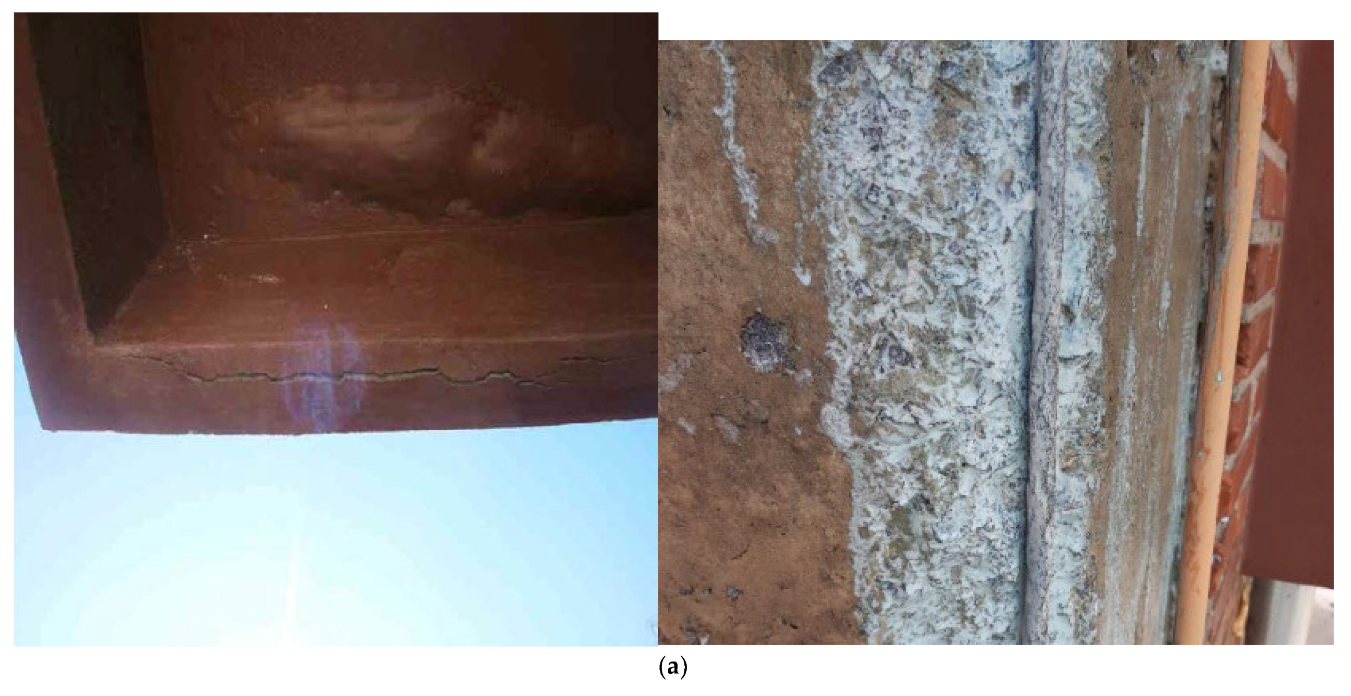
The report obtained using the ITE-PB-v3 required by the public administration shows a snapshot of the building’s state of conservation. It does not enable feedback with information generated based on that assessment and contained in other documents indicating the repair actions carried out and how they were executed. Indeed, the information generated is UNCONNECTED. On the one hand, there is a report assessing the building’s state of conservation (.doc format and folder of xml files). On the other, the plan produced by the architectural team [50] was delivered in PDF format to the owners, the administration and the builder. Furthermore, the project monitoring records contain some photos of the work carried out. Figure 11 shows the four instances of damage identified in the dictum, photos taken during execution of the repair work and the planimetrics set out in the rehabilitation plan; it is not possible to specifically situate them in the building.
Further, the instances of damage identified are described generally for the whole building. The report does not include the building’s planimetrics, whereby the damage is not situated. This makes its diagnosis difficult because of the lack of necessary information on the influence that natural and environmental conditioners (orientation, pollution, sunlight, rainfall, prevailing winds, etc.) may have had or the construction arrangements of materials or the building systems used in the building. For this reason, the actions envisaged in the rehabilitation plan are not adjusted to the interventions the building actually needs. Likewise, with the written information in the report, it is hard to identify and visualise which damage requires a safety measure or more urgent intervention. Interventions are therefore not prioritised, and on some occasions, actions to prepare an intervention plan and tender the work are delayed, generating dangerous situations. Figure 12 shows the diagnosis and dictum set out in the state of the building conservation report regarding the vertical structure of the building studied.
However, when the damage is set out in a BIM model designed and structured for that purpose using the proposed SCABIM methodology, the information gathered throughout the building’s life cycle ensures that the model is a living element (not a snapshot) and that all information linked to the building can be updated. The model collected and located the alterations and repairs implemented for each instance of damage, with all the complementary information parameterised by means of the digital twin structured and modelled for that purpose. Repairs could thus be monitored, and it was possible to know how and when they were done to obtain background information on the interventions carried out, to analyse whether they are recurrent and study whether the actions taken should be modified. Furthermore, more information could be extracted (regarding each instance of damage) than what is contained in the report, required by the public administration and generated using ITE-PV-v3 software, identifying the element analysed, with a photo of the damage, description of the symptoms and diagnosis, significance of the damage and safety measures. This information was complemented with photos of the repaired damage, the repair date and the link to the intervention proposals set out in the plan. The geo-localisation of each and every instance of damage to the building likewise provides a comprehensive view of how it behaves with respect to external agents, establishing reliable criteria for how and to what extent atmospheric agents affected each of the orientations so that corrective or forecasting measures and/or strategies can be established.
Furthermore, the BIM model of the building’s state of conservation makes agile visualisation of the information possible. The parameterisation of the family that identifies each instance of damage facilitated the acquisition of necessary information directly from the model through views designed for each purpose. For example, the urgency of intervention for each instance of damage classified by colours and whether safety measures are needed (activated crown), elimination from the model’s damage location feature of repaired damage, viewing of damage by groups or elements (roof, façade, structure and installations) and viewing of already repaired damage or that repaired from a given date on, among others. Figure 13 shows the locations of damage; the urgency of intervention and the need for safety measures for each of them are easily identified.
It was even possible to generate planning tables with the necessary information, filtering the parameters included in the damage location family. For example, planning tables with information on the damage, planning tables with the repaired damage (can be filtered by date), planning tables with the background of each instance of damage containing complementary information on the details set out in the intervention proposal, photo of the intervention and repair date, etc. Figure 14 depicts a planning table for diagnosis and dictum regarding the state of conservation of the vertical structure of the building studied.
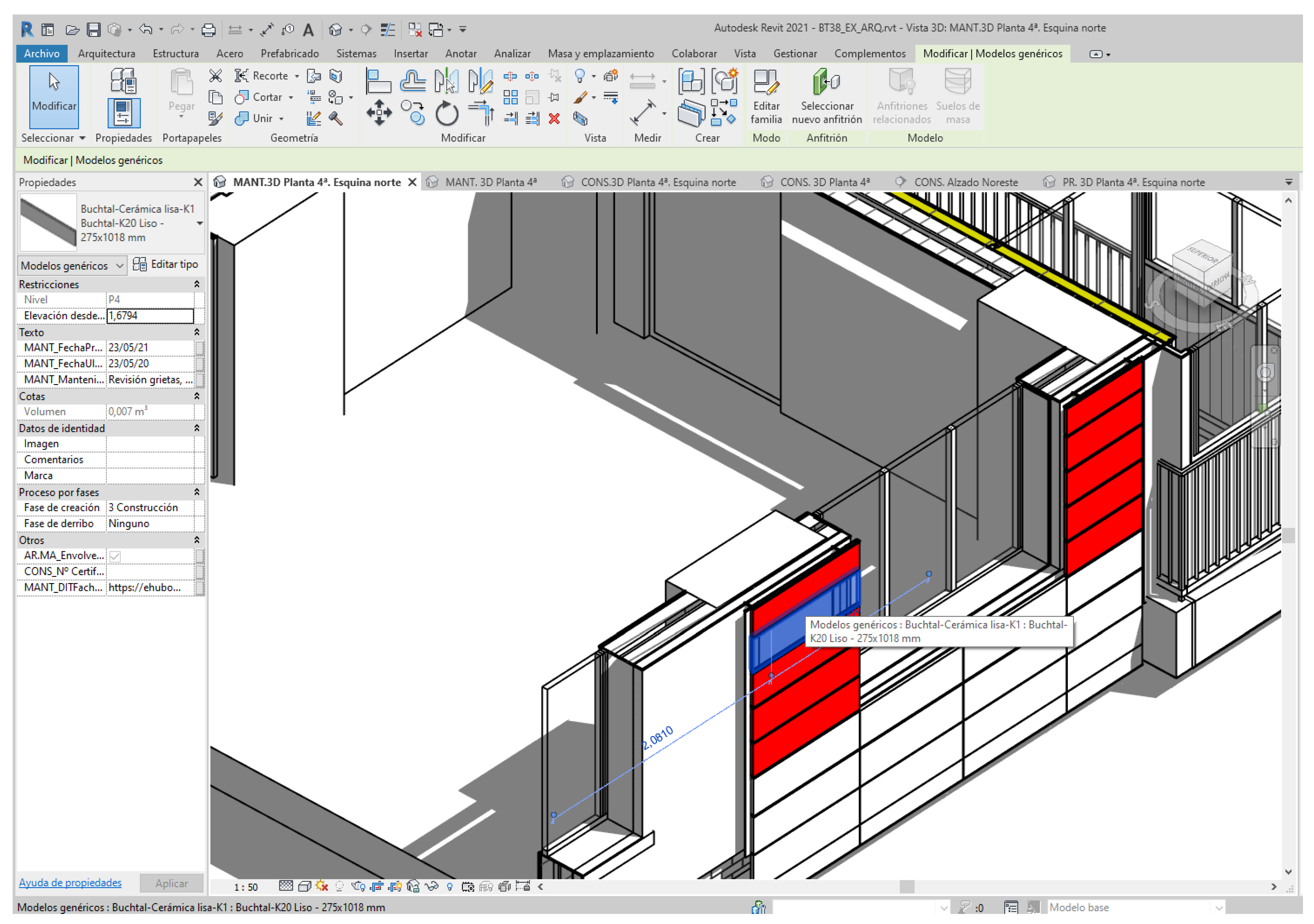
Furthermore, in the case under study, the work completed for energy improvement of the building was modelled in a new phase. The prescribed system is a Kera Twin K20-T ventilated façade cladding, consisting of plates of ceramic material supplied by AGROB-BUCHTAL GmbH, anchored using hidden mechanical fasteners to an aluminium substructure supplied by ALIVA, attached to the support. New parameters were generated for preventive maintenance of the new envelope [51], and information that may be useful for maintenance of the façade elements was linked to the model, such as the usage and maintenance manual and the technical file for the panels comprising the ventilated façade, among others. The tasks that should be carried out periodically to maintain the ventilated façade are described in these text parameters. We can thus learn from the model what maintenance work the new envelope requires. Figure 15 shows the maintenance model with the view of maintenance, identifying the need to inspect the façade plates according to the date parameters set for each exemplar.
Moreover, the model was planned so that when maintenance tables are generated, those tasks that require date-dependent review are highlighted.
Preparing the model in this manner, the maintenance that can be done is more effective. A record of inspections carried out is generated, and the model can be updated and enriched throughout the building’s life cycle.

5. Discussion

This section will discuss the impact of the proposed SCABIM methodology. The residential building situated at Calle Bertsolari Txirrita, 38, in San Sebastián, Spain, was chosen for the case study. The proposed procedure can be the departure point for existing buildings which were neither designed nor built using the BIM methodology but which implement this new methodology to manage the rest of the building’s life cycle.
The results obtained showed how the analysis of the building’s state of conservation is optimised because all existing information regarding the building (both graphic and alphanumeric) is linked to the model. It is a dynamic model that facilitates agile and up-to-date viewing and extraction of the information required at any time. This helps establish the intervention preferences depending on the urgency indicated for each instance of damage, while also ensuring rigour in diagnoses of damage and the proposed repair interventions.
The methodology proposed and validated in the case study contributes an advance in this field of knowledge and can be repeated in other residential buildings. The BIM methodology has been used above all in the phases of design and execution of newly constructed buildings. It has even been successfully applied in facility management of buildings [52,53]. There is relevant research on the use of BIM in heritage buildings (HBIM), but it focuses mainly on modelling strategies for complex geometries, such as the use of software for NURBS modelling [54].
Although some ongoing research projects study the methodology’s implementation in the rehabilitation of buildings, they [55,56] have not contributed significant results in the application of the BIM methodology to assess the state of conservation of buildings.
The new SCABIM methodology can be useful for researchers who work in the field of rehabilitation. The article also provides very practical information for agents who actively intervene in building rehabilitation processes, as they can put it into practice in their work. Those agents, however, are quite likely, not prepared to manage the information in a BIM environment, even though increasingly more technical personnel and companies specialising in rehabilitation are now getting involved in the application of BIM, making major investments to acquire equipment (hardware and software) and train their employees) [57].
Moreover, the agents who actively intervene in building rehabilitation processes are not the only ones who have to adapt to the new methodology. Its application implies the updating of the registry systems of public administrations. In this regard, it should be highlighted that very significant progress is being made in the digitalisation of processes associated with public administration thanks to aid granted by the European Union [58,59,60,61].
This notwithstanding, the proposed methodology has its limitations. New research lines have accordingly been considered to overcome them.
On the one hand, the analysis of the aspect, colour or overlap of the different instances of damage is very important information for making a correct diagnosis of damage. It is very useful for the damage to be collected in the model, indicating as faithfully as possible the respective characteristics. This requires a thorough study of the parameters that must be defined for each type of damage to thereby generate specific families for them (cracks, deformations, stains, detachments, erosion, corrosion, discolouring, etc.). On the other hand, the methodology put forward is based on a model prepared and structured using the Revit software of Autodesk. How information can be exchanged between different agents through open source files (IFC) should be studied [62,63].
Ultimately, according to the regulations governing technical inspections of buildings, they should be conducted with a periodicity of ten years. During that period, the building is outside control, and new damage can appear and cause gradual deterioration and damage to other construction elements and even harm third parties. SCABIM can conversely be a very useful tool for checking and evaluating the state of conservation of existing buildings on a continual basis. The real-time monitoring and automatic integration of this information in the model through the internet of things (IOT) [64] allows them to be continually maintained, thereby extending the buildings’ useful life.

6. Conclusions

The aim of this research is to design and structure a SCABIM model that allows a better assessment of the state of conservation of a residential building in an agile and up-to-date manner, optimising its conservation and maintenance. The starting point was the Building Technical Inspection report currently required by the Spanish public administration.
The SCABIM modelling process has been designed and structured, introducing a set of relevant building conservation state parameters in the model. This process has been applied to a case study of a high-rise residential building located in San Sebastian, Spain. The results obtained with the implementation of the proposed methodology have shown that the recording of damages and alterations in the digital twin improves access to information on the state of conservation and, therefore, its assessment.
The current analogic assessment method is based on a single written report partially describing the issues as a still image of the state of conservation of the building. However, the proposed dynamic model allows the optimisation of the effective and efficient management of the building’s life cycle. The SCABIM model contributes to the knowledge of the assessment of the state of conservation of residential buildings through BIM methodology.
The paper is a starting point for future research focused on the exchange of information between the stakeholders involved in the conservation and maintenance of assets. Additionally, future research could be focused on a more reliable representation of damages and alterations, adding real-time monitoring to optimise management. The proposed methodology implies a move towards an efficient standardisation of the building management process, within the EU’s digital strategy, in order to achieve greater efficiency and a lower environmental impact.

Author Contributions

Funding acquisition, M.S.; Investigation, M.S.; Methodology, M.S.; Project administration, M.S.; Supervision, J.P.O. and I.L.; Validation, F.M. and I.L.; Writing—original draft, M.S., J.P.O., F.M. and I.L.; Writing—review & editing, M.S., J.P.O., F.M. and I.L. All authors have read and agreed to the published version of the manuscript.

Funding

This research was funded by UPV-EHU grant number US19/10.

Informed Consent Statement

Not applicable.

Conflicts of Interest

The authors declare no conflict of interest.

Appendix A

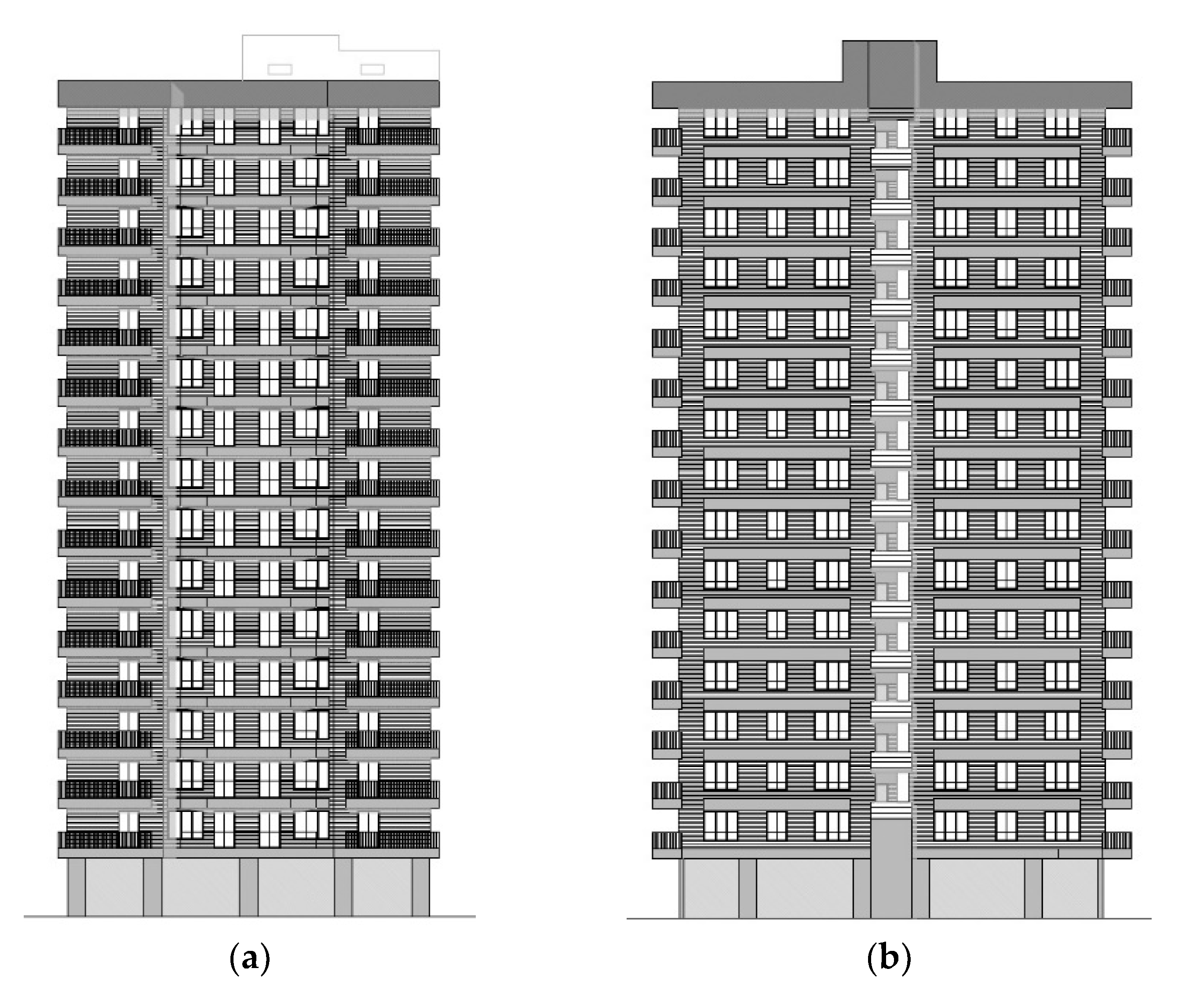
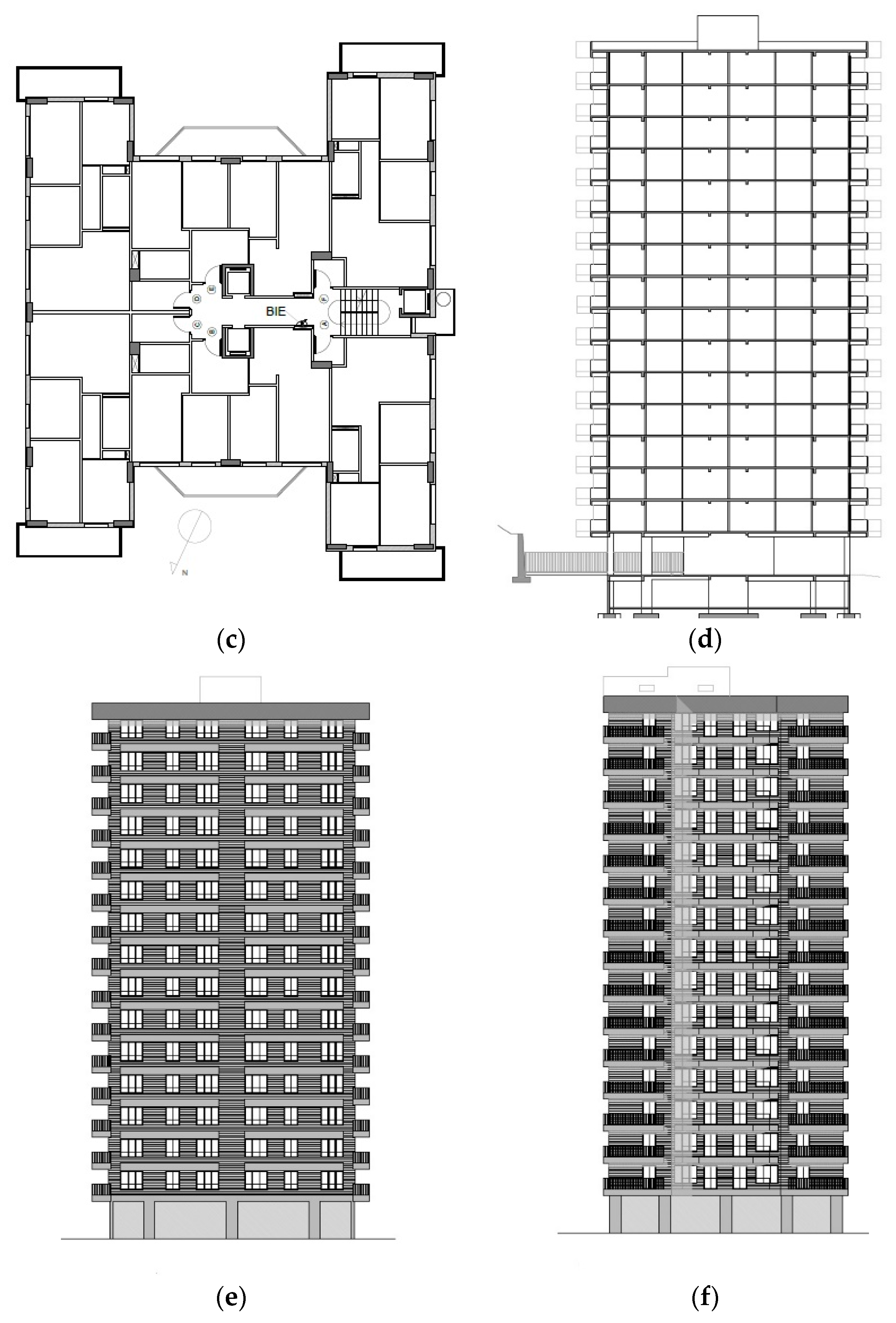
Figure A1 shows the floor plan, elevations and cross-section of the building.
Figure A1. (a) Northwest elevation; (b) southwest elevation; (c) standard plan; (d) north–south section; (e) north-east elevation; (f) southeast elevation. Source: Execution project. Bika architecture studio.
Applsci 12 07259 g0a1aApplsci 12 07259 g0a1b

References

  1. Brundland, G.H. Informe Brutland; ONU: New York, NY, USA, 1987. [Google Scholar]
  2. Amin, A.; Ali, T.; Milad, M.; Reza, A.; Saeed, R. A critical study of the existing issues in manufacturing maintenancesytems: Can BIM fill the gap? Comput. Ind. 2021, 131, 103484. [Google Scholar]
  3. Edwards, R.E.; Lou, E.; Bataw, A.; Kamaruzzaman, S.N.; Johnson, C. Sustainability-led design: Feasibility of incorporating whole-life cycle energy assessment into BIM for refurbishment projects. J. Build. Eng. 2019, 24, 100697. [Google Scholar] [CrossRef]
  4. Scherer, R.J.; Katranuschkov, P. BIMification: How to create and use BIM for retrofitting. Adv. Eng. Inform. 2018, 38, 54–66. [Google Scholar] [CrossRef]
  5. Kotaji, S.; Schuurmans, A.; Edwards, S. Life-Cycle Assessment in Building and Construction: A State-of-The-Art Report; Society of Environmental Toxicology and Chemistry: Pensacola, FL, USA, 2003. [Google Scholar]
  6. Meng, Q.; Zhang, Y.Z.; Shi, W.; Wang, J.; Sun, Y.; Xu, L.; Wang, X. A review of integrated applications of BIM and related technologies in whole building life cycle. Eng. Constr. Archit. Manag. 2020, 27, 1647–1677. [Google Scholar] [CrossRef]
  7. Aparicio, F.B. Guía BIM para Propietarios y Gestores de Activos; Building Smart Spanish Chapter: Madrid, Spain, 2020. [Google Scholar]
  8. Azapagic, A. Life cycle assessment and its application to process selection, design and optimisation. Chem. Eng. J. 1999, 73, 1–21. [Google Scholar] [CrossRef]
  9. Eastman, C.; Teicholz, P.; Sacks, R.; Liston, K. BIM Handbook—A Guide to Building Information Modeling for Owners, Managers, Designers, Engineers, and Contractors; John Wiley & Sons: Hoboken, NJ, USA, 2011. [Google Scholar]
  10. Entzian, K.; Scharmann, R. BIM für Bauen im Bestand. In Building Information Modeling; Borrmann, A., Köing, M., Koch, C., Beetz, J., Eds.; Springer Vieweg: Wiesbaden, Germany, 2015; pp. 371–383. [Google Scholar]
  11. Elagiry, M.; Marino, V.; Lasarte, N.; Elguezabal, P.; Messervey, T. BIM4Ren: Barriers to BIM implementation in renovation processes in the Italian market. Buildings 2019, 9, 200. [Google Scholar] [CrossRef] [Green Version]
  12. Lasarte, N.; Elguezabal, P.; Sagarna, M.; Leon, I.; Otaduy, J.P. Challenges for Digitalisation in Building Renovation to Enhance the Efficiency of the Process: A Spanish Case Study. Sustainability 2021, 13, 12139. [Google Scholar] [CrossRef]
  13. Etxepare, L.; Leon, I.; Sagarna, M.; Lizundia, I.; Uranga, E.J. Advanced intervention protocol in the energy rehabilitation of heritage buildings: A Miñones Barracks case study. Sustainability 2020, 12, 6270. [Google Scholar] [CrossRef]
  14. Nieto, J.E.; Moyano, J.J.; Rico, F.; Antón, D. La necesidad de un modelo de información aplicado al patrimonio arquitectónico. In Proceedings of the 1st Congress EUBIM, Valencia, Spain, 23–24 May 2013. [Google Scholar]
  15. Xiong, X.; Adan, A.; Akinci, B.; Huber, D. Automatic creation of semantically rich 3D building models from laser scanner data. Autom. Constr. 2013, 31, 325–337. [Google Scholar] [CrossRef] [Green Version]
  16. Jordan-Palomar, I.; Tzortzopoulos, P.; García-Valldecabres, J.; Pellicer, E. Protocol to manage heritage-building interventions using heritage building information modelling (HBIM). Sustainability 2018, 10, 908. [Google Scholar] [CrossRef] [Green Version]
  17. Becerik, B.; Pollalis, S. Computer Aided Collaboration in Managing Construction; Harvard University Graduate School of Design: Cambridge, MA, USA, 2006. [Google Scholar]
  18. Grilo, A.; Jardim-Gonçalves, R. Value proposition on interoperability of BIM and collaborative working environments. Autom. Constr. 2010, 19, 522–530. [Google Scholar] [CrossRef]
  19. Rodrigues, F.; Matos, R.; Alves, A.; Ribeirinho, P.; Rodrigues, H. Building life cycle applied to refurbishment of a traditional building from Oporto, Portugal. J. Build. Eng. 2018, 17, 84–95. [Google Scholar] [CrossRef] [Green Version]
  20. Volk, R.; Stengel, J.; Schultmann, F. Building Information Modeling (BIM) for existing buildings—Literature review and future needs. Autom. Constr. 2014, 38, 109–127. [Google Scholar] [CrossRef] [Green Version]
  21. Teicholz, P. Labor productivity declines in the construction industry: Causes and remedies. AECbytes Viewp. 2004, 4, 2004. [Google Scholar]
  22. Lee, S.; Akin, Ö. Augmented reality-based computational fieldwork support for equipment operations and maintenance. Autom. Constr. 2011, 20, 338–352. [Google Scholar] [CrossRef]
  23. Seeley, I.H. Building Maintenance, 2nd ed.; Palgrave: New York, NY, USA, 1987. [Google Scholar]
  24. Isailović, D.; Stojanovic, V.; Trapp, M.; Richter, R.; Hajdin, R.; Döllner, J. Bridge damage: Detection, IFC-based semantic enrichment and visualization. Autom. Constr. 2020, 112, 103088. [Google Scholar] [CrossRef]
  25. European Comission. Building Information Modelling in the EU Construction Sector; European Construction Sector Observatory: Brussels, Belgium, 2019. [Google Scholar]
  26. Masciotta, M.G.; Morais, M.J.; Ramos, L.F.; Oliveira, D.V.; Sanchez-Aparicio, L.J.; Gonzalez-Aguilera, D. A digital-based integrated methodology for the preventive conservation of cultural heritage: The experience of HeritageCare Project. Int. J. Archit. Herit. 2021, 15, 844–863. [Google Scholar] [CrossRef]
  27. Demian, P.; Walters, D. The Advantages of Information Management through Building Information Modelling. Constr. Manag. 2013, 32, 1153–1165. [Google Scholar] [CrossRef]
  28. Cerić, A.; Završki, I.; Vukomanović, M.; Ivić, I.; Nahod, M.M. Implementacija BIM-a u održavanju građevina. Građevinar 2019, 71, 889–900. [Google Scholar]
  29. Singh, V.; Gu, N.; Wang, X. A theoretical framework of a BIM-based multi-disciplinary collaboration platform. Autom. Constr. 2011, 20, 134–144. [Google Scholar] [CrossRef]
  30. Abellán, J.M.; Duque, J.A.; Buendía, J.I.; García, M. BIM en edificios de casi 1000 años. In Proceedings of the 11th Congress EUBIM, Valencia, Spain, 18–21 May 2022. [Google Scholar]
  31. Levine, N.M.; Spencer, B.F. Post-Earthquake Building Evaluation Using UAVs: A BIM-Based Digital Twin Framework. Sensors 2022, 22, 873. [Google Scholar] [CrossRef]
  32. Fang, T.; Zhao, Y.; Gong, J.; Wang, F.; Yang, J. Investigation on Maintenance Technology of Large-Scale Public Venues Based on BIM Technology. Sustainability 2021, 13, 7937. [Google Scholar] [CrossRef]
  33. Eskandari, N.; Noorzai, E. Offering a preventive solution to defects in commercial building facility system using BIM. Facilities 2021, 39, 859–887. [Google Scholar] [CrossRef]
  34. Ma, L.; Sacks, R.; Zeibak-Shini, R.; Aryal, A.; Filin, S. Preparation of synthetic as-damaged models for post-earthquake BIM reconstruction research. J. Comput. Civ. Eng. 2016, 30, 4015032. [Google Scholar] [CrossRef] [Green Version]
  35. Echávarri, F. Proyecto para 90 Viviendas y Locales en el Polígono 13, Alza, San Sebastián, Donostia/San Sebastián, Spain, 1972.
  36. Echávarri, F. Proyecto de Urbanización Parcela 117, Polígono 13, Alza, San Sebastián, Donostia/San Sebastián, Spain, 1973.
  37. Echávarri, F. Proyecto Urbanización Parcela 117, Polígono 13, Alza, San Sebastián (Primer Reformado), Donostia/San Sebastián, Spain, 1973.
  38. Bruno, S.; De Fino, M.; Fatiguso, F. Historic Building Information Modelling: Performance assessment for diagnosis-aided information modelling and management. Autom. Constr. 2018, 86, 256–276. [Google Scholar] [CrossRef]
  39. Departamento de Medio Ambiente, Planificación Territorial y Vivienda. DECRETO 117/2018, de 24 de Julio, de la Inspección Técnica de los Edificios en la Comunidad Autónoma del País Vasco. 2018. Available online: http://www.euskadi.eus/bopv2/datos/2018/09/1804416a.pdf (accessed on 10 June 2022).
  40. Departamento de Planificación Territorial, Vivienda y Transportes. EUSKOREGITE. Available online: https://www.euskadi.eus/web01-a2ite/es/contenidos/informacion/contite20200608_area_trabajo/es_def/index.shtml (accessed on 10 June 2022).
  41. Messner, J.; Anumba, C.; Dubler, C.; Goodman, S.; Kasprzak, C.; Kreider, R.; Zikic, N. BIM Project Execution Planning Guide; Computer Integrated Construction Research Program; The Pennsylvania State University: State College, PA, USA, 2019. [Google Scholar]
  42. Lin, Y.C.; Chen, Y.P.; Huang, W.T.; Hong, C.C. Development of BIM execution plan for BIM model management during the pre-operation phase: A case study. Buildings 2016, 6, 8. [Google Scholar] [CrossRef] [Green Version]
  43. Alonso, J. Nivel de desarrollo LOD. Definiciones, innovaciones y adaptación a España. Span. J. BIM 2015, 15, 40–55. [Google Scholar]
  44. BIMForum. Level of Development Specification Guide. 2017. Available online: https://bimforum.org/lod/ (accessed on 10 June 2022).
  45. Zeibak-Shini, R.; Sacks, R.; Ma, L.; Filin, S. Towards generation of as-damaged BIM models using laser-scanning and as-built BIM: First estimate of as-damaged locations of reinforced concrete frame members in masonry infill structures. Adv. Eng. Inform. 2016, 30, 312–326. [Google Scholar] [CrossRef]
  46. Guzzetti, F.; Anyabolu, K.; D’Ambrosio, L.; Marchetti Guerrini, G. From Cloud to BIM Model of the Built Environment: The Digitized Process for Competitive Tender, Project, Construction and Management. In Digital Transformation of the Design, Construction and Management Processes of the Built Environment, Research for Development; Daniotti, B., Gianinetto, M., Della Torre, S., Eds.; Springer Vieweg: Wiesbaden, Germany, 2020; pp. 17–26. [Google Scholar]
  47. Bazán, Á.M.; Alberti, M.G.; Álvarez, A.A.A.; Pavón, R.M.; González Barbado, A. BIM-Based Methodology for the Management of Public Heritage. CASE Study: Algeciras Market Hall. Appl. Sci. 2021, 11, 11899. [Google Scholar] [CrossRef]
  48. Morea, J.M.; Zaragoza, J.M. BIM en Edificios Existentes; COATAM: Madrid, Spain, 2016. [Google Scholar]
  49. Garoña, O.; Diaz de Ilarraza, M. Informe de Inspección Técnica de Edificios (ITE). Torre Aislada de Viviendas, Paseo Bertsolari Txirrita, 38, Donostia/San Sebastián, Spain, 2015.
  50. Diaz de Ilarraza, M. Proyecto de Ejecución para Rehabilitación de Fachadas en Bertsolari Txirrita, 38, Donostia/San Sebastián, Spain, 2018.
  51. Fregonese, L.; Achille, C.; Adami, A.; Fassi, F.; Spezzoni, L.; Taffurelli, L. BIM: An integrayed model for planned and preventive maintenance of architectural heritage. In Proceedings of the Digital Heritage, Granada, Spain, 28 September–2 October 2015. [Google Scholar]
  52. Kiviniemi, A.; Codinhoto, R. Challenges in the Implementation of BIM for FM-Case Manchester Town Hall Complex. In Proceedings of the International Conference on Computing in Civil and Building Engineering, Orlando, FL, USA, 23–25 June 2014. [Google Scholar]
  53. Chen, W.; Chen, K.; Cheng, J.C.; Wang, Q.; Gan, V.J. BIM-based framework for automatic scheduling of facility maintenance work orders. Autom. Constr. 2018, 91, 15–30. [Google Scholar] [CrossRef]
  54. ISO 16739:2013; Industry Foundation Classes (IFC) for Data Sharing in the Construction and Facility Management industries. International Organization for Standardization: Geneva, Switzerland, 2013.
  55. Vishnivetskaya, A.; Mikhailova, A. Employment of BIM technologies for residential quarters renovation: Global experience and prospects of implementation in Russia. Mater. Sci. Eng. 2019, 497, 12020. [Google Scholar] [CrossRef] [Green Version]
  56. Poirier, E.A.; Staub-French, S.; Forgues, D. Assessing the performance of the building information modeling (BIM) implementation process within a small specialty contracting enterprise. Can. J. Civ. Eng. 2015, 42, 766–778. [Google Scholar] [CrossRef]
  57. Colegio Oficial de Arquitectos Vasco-Navarro. Convenio Entre el Ayuntamiento de Vitoria-Gasteiz y el Colegio Oficial de Arquitectos Vasco-Navarro para la Descarga Telemática de Documentación Técnica en Expedientes de Licencias de Obras; Colegio Oficial de Arquitectos Vasco-Navarro: Vitoria-Gasteiz, Spain, 2017. [Google Scholar]
  58. TaskGroup EUBIM. Manual para la Introducción de la Metodología BIM por Parte del Sector Público Europeo; Co-Funded by the European Union; TaskGroup EUBIM: Brussels, Belgium, 2018; Available online: http://www.eubim.eu/wp-content/uploads/2018/02/GROW-2017-01356-00-00-ES-TRA-00.pdf (accessed on 10 June 2022).
  59. Leturiondo, A.; Escala, J.I.; Olarreaga, F.; Cañadas, A. Hacia una Administración Pública moderna. Experiencia de la Administración ambiental vasca. Rev. Estudios Adm. Local Auton. 2014, 1, 145–159. [Google Scholar] [CrossRef] [Green Version]
  60. The Commission to the European Parliament. EU eGovernment Action Plan 2016–2020, Accelerating the Digital Transformation of Government; The Commission to the European Parliament: Brussels, Belgium, 2016. [Google Scholar]
  61. Brumana, R.R.; Oreni, D.; Barazzetti, L.; Cuca, B.; Previtali, M.; Banfi, F. Survey and Scan to BIM Model for the Knowledge of Built Heritage and the Management of Conservation Activities. In Digital Transformation of the Design, Construction and Management Processes of the Built Environment, Research for Development; Daniotti, B., Gianinetto, M., Della Torre, S., Eds.; Springer Vieweg: Wiesbaden, Germany, 2020; pp. 391–400. [Google Scholar]
  62. Jørgensen, K.A.; Skauge, J.; Christiansson, P.; Svidt, K.; Sørensen, K.B.; Mitchell, J. Use of IFC Model Servers-Modelling Collaboration Possibilities in Practice; Department of Production, Aalborg University: Aalborg, Denmark, 2008. [Google Scholar]
  63. Martín-Garín, A.; Millán-García, J.A.; Baïri, A.; Millán-Medel, J.; Sala-Lizarraga, J.M. Environmental monitoring system based on an Open Source Platform and the Internet of Things for a building energy retrofit. Autom. Constr. 2018, 87, 201–214. [Google Scholar] [CrossRef]
  64. Soto, A.B.B.; Coral, D.S.B.; Parra, P.A.A.; Charry, O.J.P.; Muñoz, H.A.B.; Torres, D.A.Q.; Rojas, J.S.S. Sistema basado en internet de las cosas (IoT) para la monitorización en tiempo real de variables de temperatura y humedad en un equipo de refrigeración de área de farmacia de un hospital de cuarto nivel. In Proceedings of the 2nd Congreso Lationoamericano de Ingenieria, Cartagena de Indias, Colombia, 10–13 September 2019. [Google Scholar]
Figure 1. Workflow for producing the report on a building’s state of conservation.
Applsci 12 07259 g001
Figure 2. Flow chart of the SCABIM proposal process.
Applsci 12 07259 g002
Figure 3. Building at Bertsolari Txirrita, 38, in San Sebastián.
Applsci 12 07259 g003
Figure 4. (a) Control points on the ground, roof and north and west façades; (b) control points on the ground, roof and north and east façades; (c) control points on the ground, roof and south and east façades.
Applsci 12 07259 g004
Figure 5. (a) Relation of LEICA RTC 360 laser scanning stations; (b) point cloud of the building.
Applsci 12 07259 g005
Figure 6. (a) Three-dimensional model of the building; (b) set of models linked to the architectural model: ‘datum’ model, MEP model and structural model.
Applsci 12 07259 g006
Figure 7. Family of the element used to locate instances of damage.
Applsci 12 07259 g007
Figure 8. Creation of shared parameters in Revit.
Applsci 12 07259 g008
Figure 9. Creation of dropdown menu parameters using key-type planning tables.
Applsci 12 07259 g009
Figure 10. Generation of filters to change the visibility of each instance of damage according to the urgency of intervention.
Applsci 12 07259 g010
Figure 11. Information generated is unconnected. (a) Photo in the report: carbonatation of reinforced concrete and photo taken while monitoring work to repair the carbonatation; (b) photo in the report of condensation moisture stains, photo in the documentation on monitoring the work on energy improvement of the envelope and detail of the intervention set out in the rehabilitation plan; (c) photo in the report of areas of dampness from leaks and efflorescence due to poor waterproofing of overhanging balcony slabs, photo in the documentation on monitoring the intervention work on those slabs and detail in the rehabilitation plan; (d) photo in the report of railing anchor detachment, photo in the documentation on the monitoring of work to replace the railings and detail in the rehabilitation plan.
Applsci 12 07259 g011aApplsci 12 07259 g011b
Figure 12. Excerpted from the Building Technical Inspection report required by the public administration and generated using ITE-PV-v3 software. Diagnosis and dictum on the state of conservation of the vertical structure of the building studied.
Applsci 12 07259 g012
Figure 13. Three-dimensional model of the building’s state of conservation. Instances of damage are located, showing the intervention urgency and the need for safety measures according to the colours established for each case: red = immediate intervention; orange = very urgent intervention; yellow = urgent intervention; blue = intervention needed in the medium term; green = maintenance. The activated crowns indicate the need for safety measures.
Applsci 12 07259 g013
Figure 14. Diagnosis and dictum on the state of conservation of the vertical structure of the building studied.
Applsci 12 07259 g014
Figure 15. Maintenance model. View of maintenance, identifying the need to inspect façade plates according to the date parameters set for each exemplar. Source: own creation.
Applsci 12 07259 g015
Table 1. Pre-set parameters in the protocol for conducting the technical inspection of a building.
State of ConservationSeverity of DamageAssessment of Intervention
Apparently goodNo apparent riskImmediate (<24 h)
Constructive deterioration and deficienciesRisk to other construction elementsVery urgent (<3 months)
Cannot be determinedRisk of progressive deteriorationUrgent (<12 months)
Specific deficienciesRisk to third partiesNecessary in medium term
Extreme deterioration Maintenance
Table 2. Set of parameters on the building’s state of conservation.
Parameter SetParameterDescriptionHierarchyType
General Data (GD)GD_ProjectProject namePText
GD_PhaseProject phasePDropdown menu
GD_AddressProject addressPText
Architectural Data (AD)AD_Original ProjectOriginal project documentationPURL-PDF
AD_BTIBuilding Technical Inspection documentationPURL-PDF
SC_Damage CodeDamage codificationIText
State of Conservation (SC)SC_State of ConservationState of conservation of the analysed elementI (instance)Dropdown menu
SC_Group or elementAnalysed group or elementIText
SC_SubgroupAnalysed subgroupIText
SC_SymptomsSymptoms descriptionIMulti-linear text
SC_ImageImage of the elementIURL-image
SC_ Severity of damageSeverity of the damageIDropdown menu
SC_DiagnosisDescription of possible causesIMulti-linear text
Damage Assessment (DA)DA_AssessmentUrgency of the interventionIDropdown menu
DA_ObservationsExplanatory notesIText
DA_Safety measuresNeed for safety measuresIYes/no
Repairs (RP)RP_Start date of repairsStart date of repairsIEntire
RP_End date of repairsEnd date of repairsIEntire
RP_RepairedDamage repairedIYes/no
RP_Repair documentationDocumentation of repair solutionIURL-PDF
Publisher’s Note: MDPI stays neutral with regard to jurisdictional claims in published maps and institutional affiliations.