Abstract
In order to study the dynamic response characteristics of a pile-soil foundation when an adjacent tunnel exists, both model tests and numerical simulations were performed in this study. Taking the peak vibration acceleration, peak vibration velocity, and peak vibration displacement as the evaluation indexes of the dynamic response, the dynamic response of the pile-soil foundation with an adjacent tunnel under high-speed train loads is studied. A method of dividing the affected zones of the dynamic response based on the safety threshold is provided in this paper, which can evaluate the safety of the adjacent tunnel under the action of train load. Additionally, the effect of train speed on dynamic response is further analyzed. The results show that the dynamic response index inside the foundation decays significantly with increasing distance from the surface when the train load is applied, regardless of the presence or absence of the adjacent tunnel. Compared with an ordinary pile-soil foundation, the dynamic response indexes inside the foundation increase significantly when there is an adjacent tunnel. With the increase in the horizontal distance from the pile foundation, the distribution characteristics of the horizontal transverse direction of each dynamic response index inside the foundation change from a “wavy” distribution to a monotonically decreasing distribution. According to the safety threshold of vibration velocity, the foundation is divided into the hazardous affected zone, strongly affected zone, and weakly affected zone, and then the corresponding vibration reduction measures are adopted. With the increase in train speed, the effect of tunnel structure on the attenuation of dynamic response in a pile-soil foundation becomes more obvious.
1. Introduction
In China, the country’s transportation infrastructure facilities are increasingly improved. In 2021, the total operating mileage of China’s railways exceeded 150,000 km and the operating mileage of China’s high-speed railways exceeded 40,000 km. More than 4000 km of railways have been added, including 2150 km of high-speed railways [1,2]. More and more high-speed trains are running on high-speed railways between cities. As a typical vibration load, the vibration load of high-speed trains induces the dynamic response of the pile-soil foundation and nearby structures [3,4,5,6]. Under a long-term vibration load, nearby structures may have problems such as cracking and concrete block spalling, and the original damage and destruction have a more adverse impact on the structure [7,8]. Therefore, it is of great significance to study the characteristics and propagation law of the dynamic response of a pile-soil foundation with an adjacent tunnel under vibration train load and to provide a theoretical basis for the safety evaluation of the adjacent tunnel of similar projects under train load.
For the effect of high-speed train loads, Yang et al. [8,9] used the frequency response function and peak vibration acceleration as evaluation indexes to carry out a model test of train single-point vibration load and studied the dynamic response of a tunnel structure and its surrounding soil under train vibration load. In an engineering case where significant settlement occurred during a railway trial run, Gu et al. [10] used numerical simulations to investigate the excess pore water pressure in soft soils caused by cyclic train loads and to predict the long-term settlement of the foundation under train operation. The results showed that, without proper treatment, the railway will experience more severe settlement. Niu et al. [11] conducted a large-scale pile embankment model test to analyze the soil pressure, settlement, and strain of pile foundations under the action of high-speed trains on a pile network composite foundation. The analysis results showed that the cumulative settlement of the foundation under the action of long-term vibration still tends to increase. Tang et al. [12] studied and verified the dynamic response of geosynthetic reinforced pile foundations (GRPF) under train loads using a three-dimensional time-domain viscoelastic finite element method (FEM), considering different train speeds and pile group arrangements during high-speed train operation. Shen et al. [13] investigated the settlement pattern of soft clay subgrade under cyclic principal stress rotation caused by high-speed train load. Fu et al. [2] and Dong et al. [14] investigated the dynamic characteristics of XCC pile-raft foundation under high-speed train loads and a heavy-haul embankment reinforced by micro-piles by model tests and 3D numerical simulation.
The operation of high-speed trains can have a certain adverse effect on ordinary soft ground and pile-soil composite foundations, which can even threaten the safe operation of high-speed trains in severe cases if not handled properly. Due to the constraints of urban underground space resources, there are crisscross tunnel projects. When a tunnel project close to a high-speed railway appears, there must be a greater risk from the construction point of view alone [15,16,17,18,19]. In contrast, a pile-soil composite foundation with the presence of an adjacent tunnel under high-speed train loads is more complex than the ordinary pile-soil composite foundation, and the differences in dynamic response characteristics are unknown. Moreover, there is also a lack of relevant research on the safety evaluation of an adjacent tunnel under the action of train load.
Based on the Xi’an Metro Line 14 under the Daxi high-speed railroad, physical model tests and numerical simulations are conducted in this study to explore the effect of the adjacent tunnel on the dynamic response properties of pile-soil foundations under high-speed train loads, and the dynamic response is compared and analyzed with that of ordinary pile-soil composite foundations. According to the safety threshold of peak velocity, the affected zones of the dynamic response are divided and the safety of the adjacent tunnel is evaluated. Additionally, the effect of the train speed on the dynamic response of the pile-soil foundation is further studied. This paper provides an important reference for the dynamic response analysis of the pile-soil foundation with an adjacent tunnel under high-speed train loads and their safety evaluation.
2. Model Test
2.1. Project Overview
This paper is based on the tunnel section between Shangxian Road Station and Xuefu Road Station of Xi’an Metro Line 14 (hereinafter referred to as the “Shang-Xue section”), which runs under a special bridge section of the Datong–Xi’an High-speed Railway over the Xi’an–Tongchuan Highway. The bridge is a typical 32 m simply supported box girder, in which the plane size of the bearing platform of the high-speed railway bridge is 6.8 m × 12.2 m, and the height is 2.5 m. Eight bored piles are installed under each bearing platform, and the diameter of the pile foundation is 1.25 m. The outer diameter of the shield tunnel tube is 6.0 m, the thickness is 0.3 m, and the ring width is 1.5 m. The minimum distance of the tunnel from the pile foundation is 3.78 m. Figure 1 shows the relationship between the location of the subway interval tunnel and the HSR bridge.
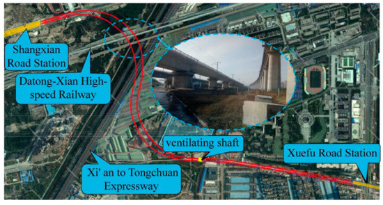
Figure 1.
Location relationship between the Shang–Xue interval and the high-speed railway bridge.
2.2. Similarity Ratios and Material Parameters
This model test focuses on the dynamic response of a pile-soil composite foundation with an adjacent tunnel under the load of a high-speed railway. The deformation of the structural model is mainly elastic deformation, so only the elastic similarity criterion needs to be satisfied [20,21,22]. The base similarity ratio of this model test was determined after full consideration of the feasibility and periodicity of the test. The parameters are as follows: geometric similarity ratio Cl = 20, density similarity ratio Cρ = 1, and elastic modulus similarity ratio CE = 14.2. According to similarity theory, other experimental similarities are obtained as shown below: acceleration similarity ratio Ca = 1, velocity similarity ratio Cv = CE0.5Cρ−0.5 = 3.77, time similarity ratio Ct = ClCρ0.5CE−0.5 = 5.31, frequency similarity ratio Cω = Ct−1 = 0.19, and load similarity ratio CF = Cl3Cρ = 8000.
Due to the complexity of considering the moving train loads in a model test, the application of a single-point vibration load can be considered for simulation [8,9]. This test mainly focuses on the dynamic response of a pile-soil composite foundation and tunnel under the high-speed railway train loads, so the bridge deck structure is simplified, and only the bridge pile foundation and tunnel structure can be considered.
Compared to traditional plaster, Plexiglas is physically stable, easy to mold, eliminates the demolding process and has higher model strength. The structure of this model test (pile and tunnel lining) was simplified and simulated uniformly using suitable Plexiglas, from Longxin Chemical Co., Ltd., Heilongjiang, China. In order to restore the stress state of the pile foundation as much as possible, a mixture of epoxy resin and sand is applied around the pile foundation to increase the friction of the pile foundation. The model test stratum is formulated with reference to the actual stratum using sand and clay. Uniaxial compression tests were conducted to measure the mechanical parameters of the soil and plexiglass. The mechanical parameters of the prototype and the model for the soil and structure are given in Table 1, respectively.

Table 1.
Dimensions and mechanical parameters of soil and structural components.
2.3. Design of the Test System
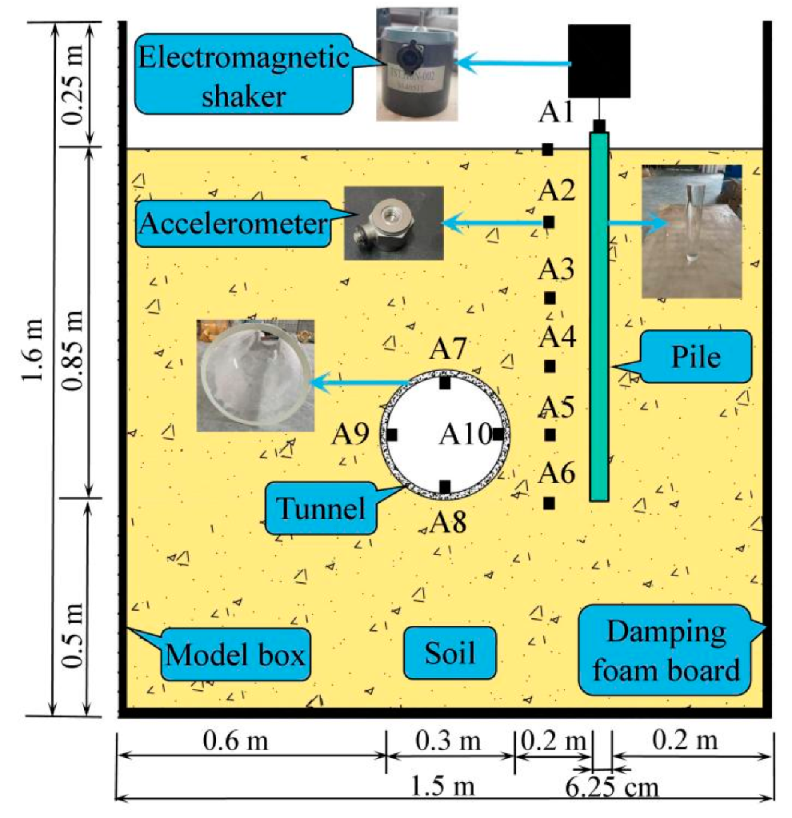
In order to carry out relevant research, a dedicated single-point train vibration load model test system was developed, which mainly consists of three parts: a model test box, a loading system, and a dynamic response test system. The model box size is: length × width × height = 1.5 m × 1.5 m × 1.6 m. The box is mainly made of thick 5 mm steel plate and 10-gauge channel steel, welded and processed. The loading and dynamic response test system is mainly composed of a signal generator, a power amplifier, a small exciter, acceleration sensors, and a dynamic signal collector, as shown in Figure 2.
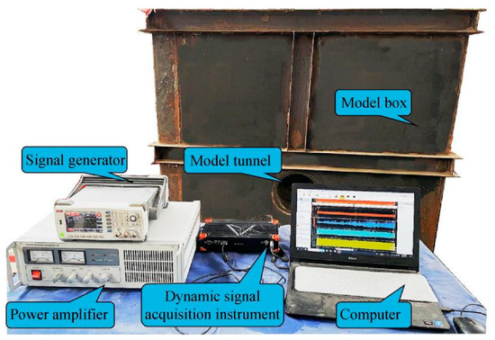
Figure 2.
Model test system.
A total of 10 miniature piezoelectric accelerometers were used to measure the response of the segmental lining and soil, where the monitoring points in the soil between the pile and tunnel were arranged from top to bottom as A1~A6, and the monitoring points inside the tunnel were arranged as A7~A10, as shown in Figure 3. Acceleration monitoring data were converted to actual data according to similar ratios to facilitate comparison and analysis.
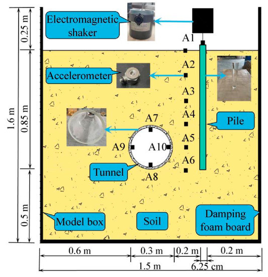
Figure 3.
Schematic layout of monitoring points.
2.4. Train Load
The vibration signals used in the test are shown in Figure 4 from Niu et al. [11], where T1 is the time for two wheel sets in a bogie to traverse a location; T2 is the time for two bogies in a carriage to traverse a location; and T3 is the time for a carriage to traverse a location. In the absence of track irregularities, the vibration frequency f caused by train operation is determined by the distance, L, between the two wheelsets on the bogie and the train speed, V, namely, f = V/L. The vibrational frequency is proportional to train speed when the type of train is known (e.g., L = 2.5 m for CRH2). When the train speed is 350 km/h, the loading frequency is 38 Hz and the loading amplitude is 372 kN [23].
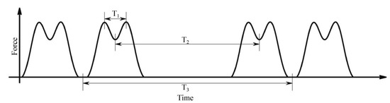
Figure 4.
M-shaped train vibration load model.
2.5. Numerical Simulation
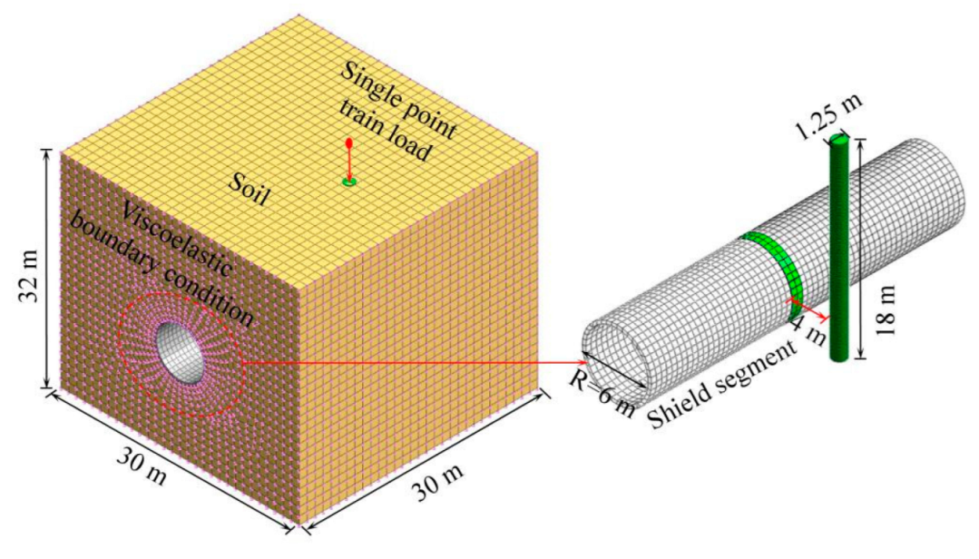
To further study the effect of proximity tunneling on the dynamic response characteristics of a pile-soil composite foundation under the vibration load of high-speed trains, the finite element software MIDAS GTS NX (MIDAS Information Technology Co., Ltd., Beijing, China) is used for three-dimensional numerical simulation in this paper. The established numerical calculation model is shown in Figure 5. The size of the numerical model is consistent with that of the model test prototype, with a length, width, and height of 30.0, 30.0, and 32 m, respectively. The physical and mechanical parameters of the soil and tunnel structure are also consistent with the prototype of the model test as shown in Table 1, and the acceleration is monitored at the same measuring point as for the model test. At the same time, to ensure the accuracy of the numerical analysis, the size of the model grid element is less than 1/10~1/8 of the wavelength corresponding to the input wave frequency [23].

Figure 5.
Numerical calculation model.
Because the tunnel deformation caused by train vibration load is generally small, the elastic constitutive model is adopted in the numerical calculation model. The pile in the numerical model is simulated by a 1D beam element and contact element. The normal contact stiffness Kn and tangential contact stiffness Kt are determined as shown in Equations (1) and (2), respectively [24].
where Es is the elastic modulus of the soil; tv is a virtual thickness used to calculate the contact element with a default of 0.5; and S is the size of unit.
In the dynamic analysis, the viscous boundary conditions proposed by Lysmer et al. [25] are used. When defining the viscous boundary, the damping values in the x, y, and z directions of the soil materials are used and calculated. The calculation formula of the damping value is as follows:
where CP and CS are tangential and normal damping ratios, respectively; ρ is the density of the material in kg /m3; W is the section coefficient of the material in kg; λ and G are Lame constants in kN/m2 with and where E is the elastic modulus of the material in kN/m2 and v is Poisson’s ratio; A is the area in m2; and cS and cP are the wave velocities of the S-wave and P-wave, respectively, and they can be determined by Equations (5) and (6).
2.6. Test Results and Discussion
To analyze the dynamic response of the pile-soil composite foundations with the adjacent tunnel under the vibration load of the railway, the peak vertical accelerations at the monitoring points (A1~A10) of the test and the numerical simulation models are extracted. The peak acceleration curves at different depths from the surface are shown in Figure 6, and the peak accelerations at different parts of the tunnel lining are shown in Figure 7.
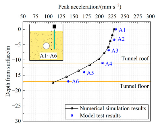
Figure 6.
Peak acceleration curves at different depths from the surface (A1~A6).
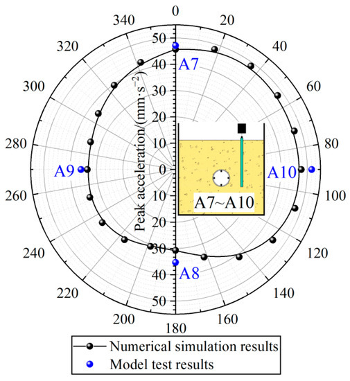
Figure 7.
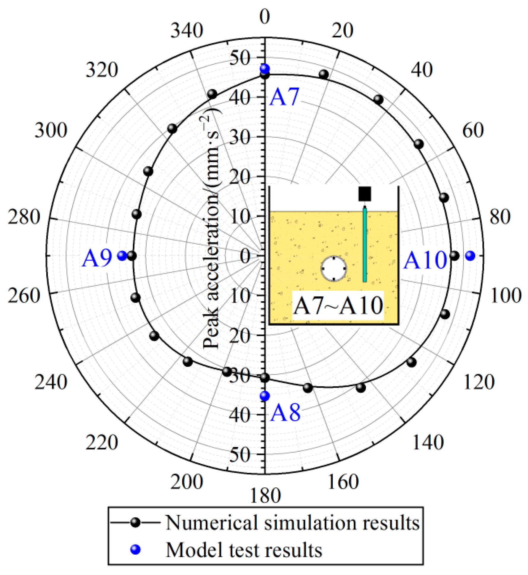
Peak acceleration at different locations of the tunnel lining (A7~A10).
It can be seen from Figure 6 that the numerical calculation results and the model test results are close and the peak accelerations at the ground surface are all maximum values, all of which exceed 225 mm·s−2. With the increase in the distance from the ground surface, the peak acceleration of the foundation under vibration load decreases continuously, especially at the buried depth of the tunnel. Figure 7 suggests that the peak accelerations of the tunnel lining are less than 50 mm·s−2, and the peak acceleration of the tunnel lining near the load point (upper side and right side) is significantly greater than that far from the load point (lower side and left side). It is mainly because the hollow tunnel structure can be approximated as a particular “vibration isolation trench” which hinders the vibration propagation in the stratum.
Chen et al. [26] determined that the thresholds of vibration acceleration, vibration velocity, and vibration displacement of underground structures under vibration load are 1 m·s−2, 10 mm·s−1, and 12 mm, respectively. Therefore, the peak vibration acceleration of the most dangerous lining section of the tunnel structure is much smaller than the safety threshold and is safe under a single-point train load, with less possibility of damage.
Comparing Figure 6 and Figure 7, the numerical simulation results are similar to the model test results, and the results are in good agreement. Therefore, numerical simulations can be used to further study the dynamic response of a pile-soil foundation with an adjacent tunnel under moving train loads.
3. Dynamic Response under the Moving Train Loads
3.1. Numerical Model and Parameters
In order to further study the effect of the adjacent tunnel on the dynamic response of pile-soil composite foundations under moving train loads, two numerical models of an ordinary pile-soil composite foundation and a pile-soil composite foundation with a proximity tunnel are established according to the project case, as shown in Figure 8. The size of the two numerical calculation models is the same, with a length, width, and height of 160, 60, and 80 m, respectively. The mechanical parameters of the soil and structure are given in Table 2, respectively. The concrete structures mainly considered in the numerical simulation include shield segments, piles, and the piers and caps of the bridge, of which the outer diameter and the thickness of shield segments are 6.0 m and 0.3 m, respectively. The diameter and the length of the pile are 1.25 m and 46 m, respectively. The size of the cushion cap is 12.2 m × 6.8 m and the width of bridge is 12.2 m. The distance between two cushion caps is 32 m. The same as for the numerical simulation in Section 2.5, the elastic constitutive model is adopted in the numerical calculation model and the viscous boundary conditions are used to restore the infinite state of the real foundation.
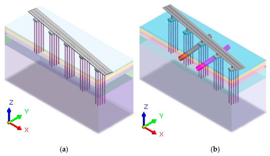
Figure 8.
Numerical calculation models. (a) Pile-soil composite foundation. (b) Pile-soil composite foundation with adjacent tunnels.
Table 2.
Stratigraphy and main structural parameters.
Before dynamic load analysis, the eigenvalue of the model should be calculated first. In Midas gts, the eigenvalue analysis can be directly carried out by establishing the elastic boundary generated by the ground spring element. The periods of the main vibration of the two numerical models in Figure 8 are shown in Table 3. In this paper, the length of the integration step is 0.005 s, which is less than 1/100 of the minimum natural vibration period, and the influence of calculation error can be ignored [27]. The results in Table 3 are input into the software as the main mode periods of the model, and the damping ratio is taken as 0.05 to solve the dynamic response of the numerical models.
Table 3.
Period of the main vibration.
3.2. Dynamic Response Laws of Different Types of Foundations
For the numerical calculation, a train speed of 350 km/h is taken. Referring to the results of Chen et al. [26] and Zhang et al. [28], the peak vibration acceleration, peak vibration velocity, and peak vibration displacement were used as the indexes to evaluate the dynamic response. The results of the vertical monitoring points between the pile foundation and the tunnel and the horizontal monitoring points at the burial depth of the tunnel axis were extracted to analyze the dynamic response of the foundation. The dynamic response indexes of the monitoring points for the two numerical models are shown in Figure 9 and Figure 10.

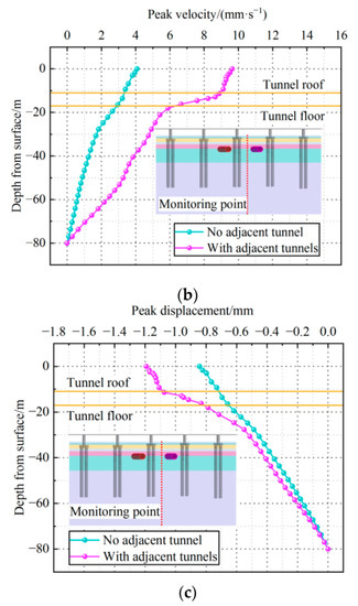
Figure 9.
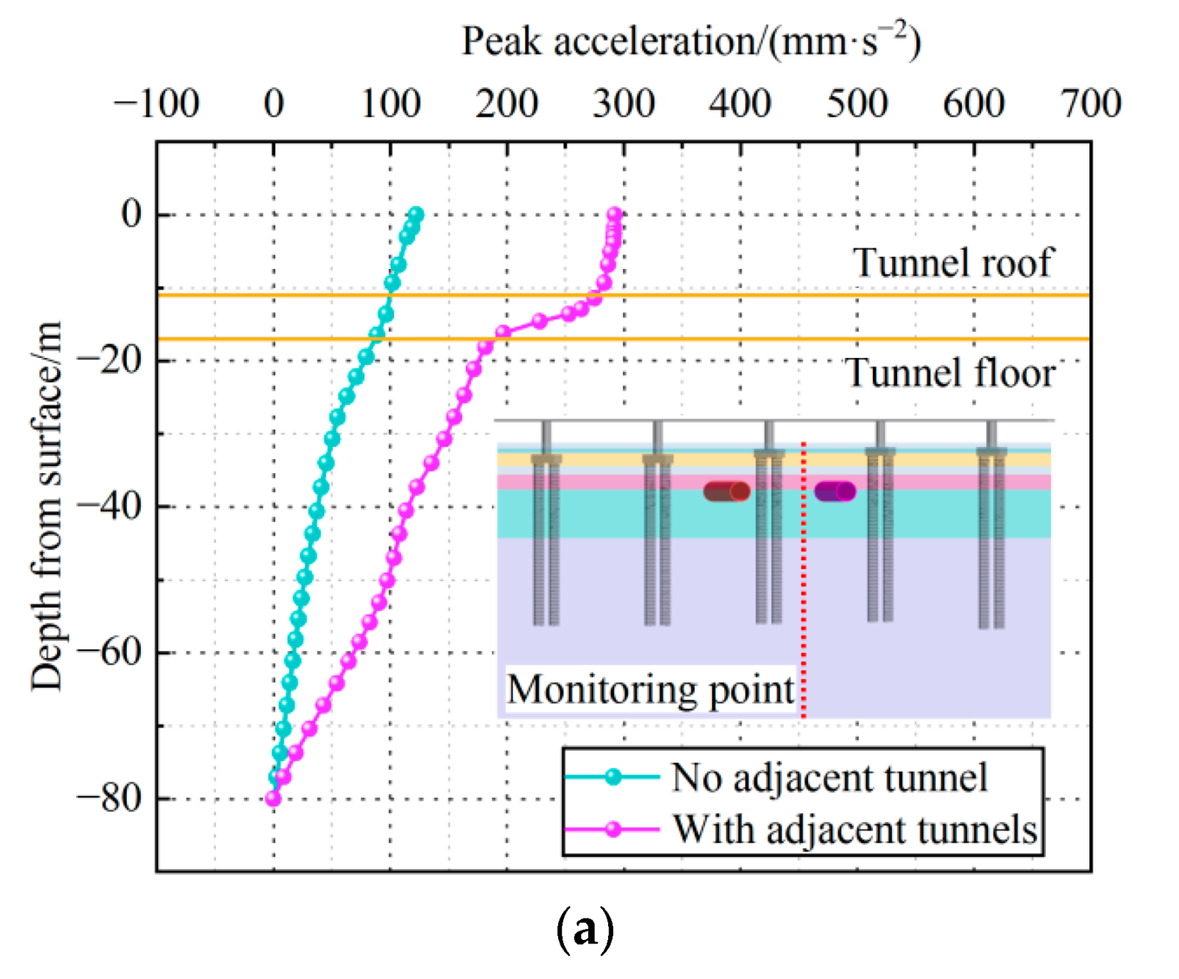
Vertical dynamic response characteristics of the foundation. (a) Peak vibration acceleration. (b) Peak vibration velocity. (c) Peak vibration displacement.
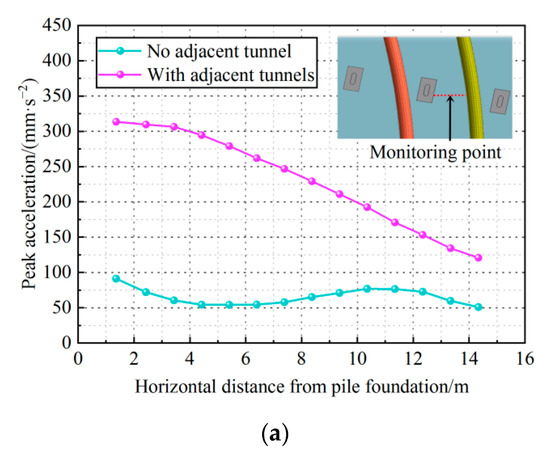
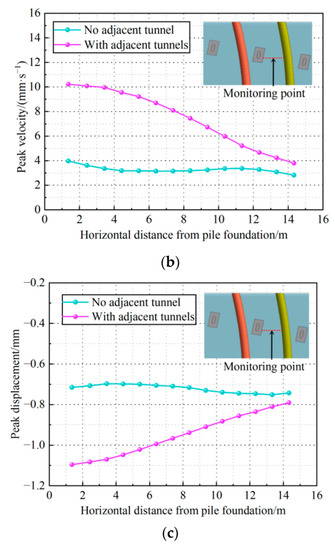
Figure 10.
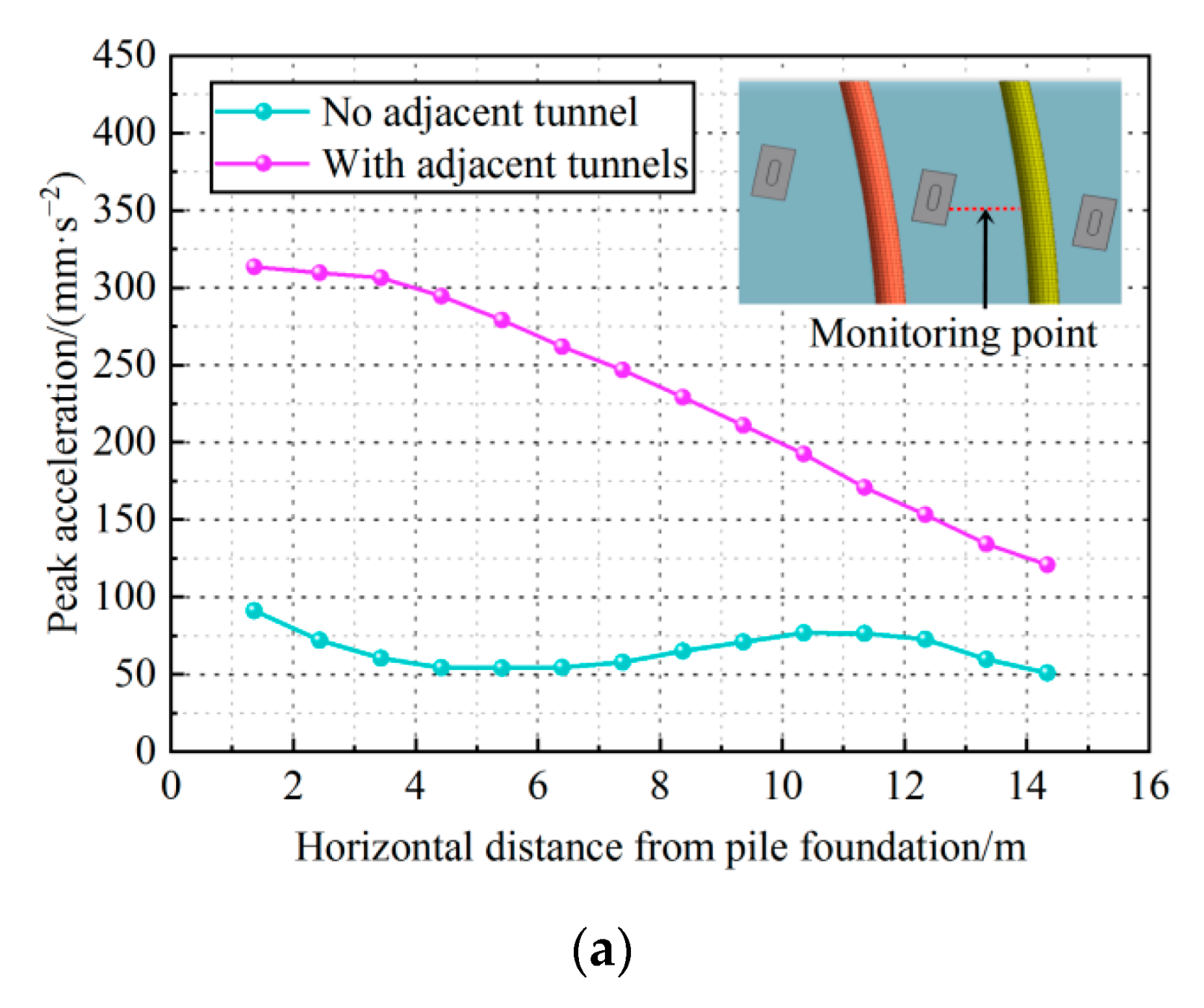
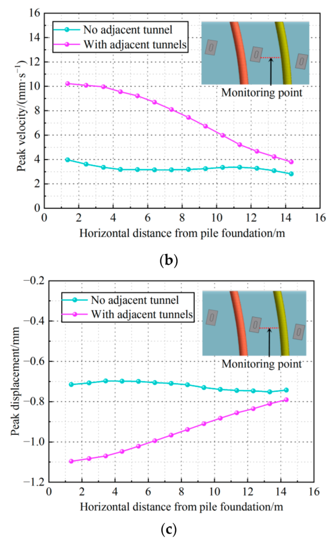
Horizontal dynamic response characteristics of the foundation. (a) Peak vibration acceleration. (b) Peak vibration velocity. (c) Peak vibration displacement.
Figure 9 shows that, when there is an adjacent tunnel, the dynamic response indexes of the foundation under the moving train loads are similar to the results of the model test. All the dynamic response indexes are at maximum at the ground surface, and the peak vibration acceleration, peak vibration velocity, and peak vibration displacement are 286.4 mm·s−2, 9.2 mm·s−1, and 1.1 mm, respectively, which meet the corresponding control thresholds. With the increase in the distance from the surface, the dynamic response indexes of both models decrease, especially at the burial depth of the adjacent tunnel. The vibration acceleration, vibration velocity, and vibration displacement peaks of the pile-soil composite foundation as a whole increase significantly in the presence of the adjacent tunnel, with the greatest increase at the burial depth of the tunnel roof, increasing by 142%, 58%, and 41%, respectively. The above analysis illustrates the strong effect of the adjacent tunnel on the dynamic response of the pile-soil foundation. Therefore, when there is an adjacent tunnel, the dynamic response of the pile-soil foundation caused by the moving train loads needs immediate attention.
Figure 10 indicates that, when there is an adjacent tunnel, the horizontal dynamic response of the foundation is still significantly greater than that of the ordinary pile-ground foundation, and, at the tunnel burial depth between the tunnel and the pile, each dynamic response index is monotonically varying, all increasing and decreasing with the distance from the pile. The dynamic response of the ordinary pile-soil foundation has a small variation, and each dynamic response index decreases and then increases with the increase in distance from the pile and has a “wavy” variation. This characteristic is due to the superimposed effect of the train vibration generated inside the foundation, which is conducted by the piles on both sides, respectively. When there is an adjacent tunnel, the tunnel prevents the vibration from propagating in the stratum, and the soil between the neighboring piles and the tunnel is less affected by the vibration of other piles, resulting in a monotonic variation in the dynamic response indexes of the foundation between the pile and the tunnel.
The peak vibration velocity is often used to evaluate damage to building structures. For the safety control threshold of the dynamic response of underground structures under moving train loads, as shown in Table 4, Zhang et al. [28] graded and supplemented the control threshold of the vibration velocity. The pile-soil foundation at the burial depth of the tunnel was divided into three affected zones according to the graded control thresholds, as shown in Figure 11.
Table 4.
Graded control thresholds for the dynamic response of underground structures.
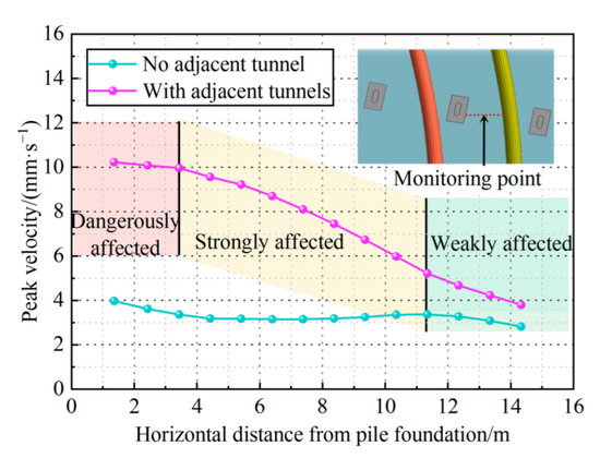
Figure 11.
Evaluation of dynamic response under moving train loads.
Figure 11 indicates that, when the pile-soil foundation has an adjacent tunnel under moving train loads, the foundation between the pile and tunnel is affected by the moving train loads and the ratio of dangerously affected zone: strongly affected zone: weakly affected zone is about 1:2:1. The peak vibration velocity of the foundation at the burial depth of the tunnel within 3.6 m from the pile (red zone) exceeds 10 mm·s−1. The foundations in this zone account for approximately 24.8% of the foundations between the piles and the tunnel. The underground structure within this zone of high-speed train operation has a large safety risk, which must be paid attention to, and corresponding damping measures must be adopted. The foundation in the range of 3.6~11.4 m near the pile (yellow zone) is the strongly affected zone, and it represents approximately 53.8% of the foundation between the piles and the tunnel. Although the vibration will not cause serious damage to the underground structure within this zone, it is still recommended to use the corresponding vibration damping measures. The foundation outside 11.4 m from the pile to the tunnel (green zone) are in the weakly affected zone, and the impact of the moving train loads on the underground structure in this area is low. This part of the foundation accounts for approximately 21.4% of the foundations between the piles and the tunnel. The importance and deterioration of the underground structure are taken into account to determine whether damping measures need to be taken. Taking this project as a case, the tunnel structure of the underpass section is in the weakly affected zone. If the tunnel is used with low requirements, such as ordinary hydraulic tunnels, the impact of moving train loads can be ignored. If the tunnel is used with high requirements, such as traffic tunnels, especially those with rails, then partial vibration damping measures can be considered. Moreover, if the adjacent tunnel has been in service, this needs to be considered in combination with the service time of the tunnel. Other, similar projects can use this treatment to evaluate the impact of moving train loads.
3.3. Effect of Train Speeds on the Dynamic Response
Based on the above analysis, train speeds of 350 km/h, 250 km/h, 200 km/h, 150 km/h, and 100 km/h were taken for calculations to study the effect of train travel speed on the dynamic response of the pile-soil foundation with the adjacent tunnel, respectively. The peak vibration acceleration, peak vibration velocity, and peak vibration displacement of the monitoring points in both the vertical and horizontal directions are shown in Figure 12 and Figure 13.
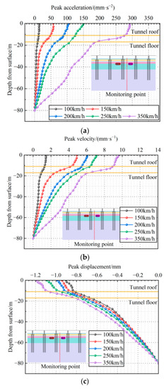
Figure 12.
Vertical dynamic response characteristics of the foundation for different train speeds. (a) Peak vibration acceleration. (b) Peak vibration velocity. (c) Peak vibration displacement.
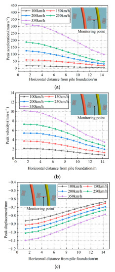
Figure 13.
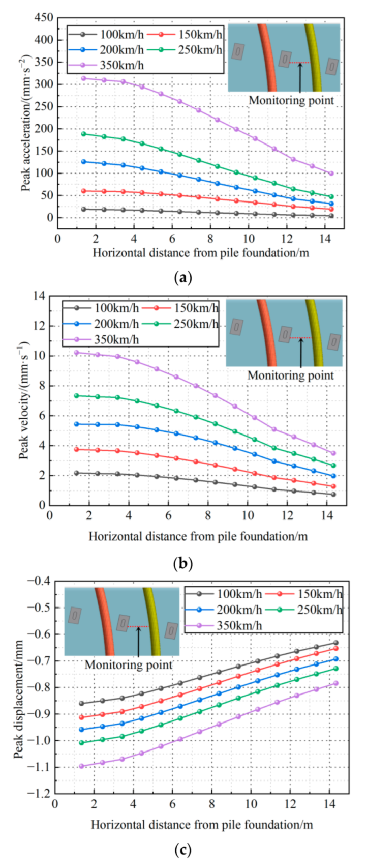
Horizontal dynamic response characteristics of the foundation for different train speeds. (a) Peak vibration acceleration. (b) Peak vibration velocity. (c) Peak vibration displacement.
Figure 12 and Figure 13 represent that the peak vibration acceleration, peak vibration velocity, and peak vibration displacement in different directions inside the foundation under different train speeds are similar. With the increase in train speed, each dynamic response index shows a positive correlation change. This is mainly due to the increase in the train speed corresponding to the increase in the moving train loads, and the dynamic response of the foundation caused by the train vibration becomes more obvious, which eventually leads to the increase in each dynamic response index. The dynamic response indexes increase the most at the surface, and the peak vibration acceleration, peak vibration velocity, and peak vibration displacement increase by 279.2 mm·s−2, 8.2 mm·s−1, and 0.29 mm, respectively.
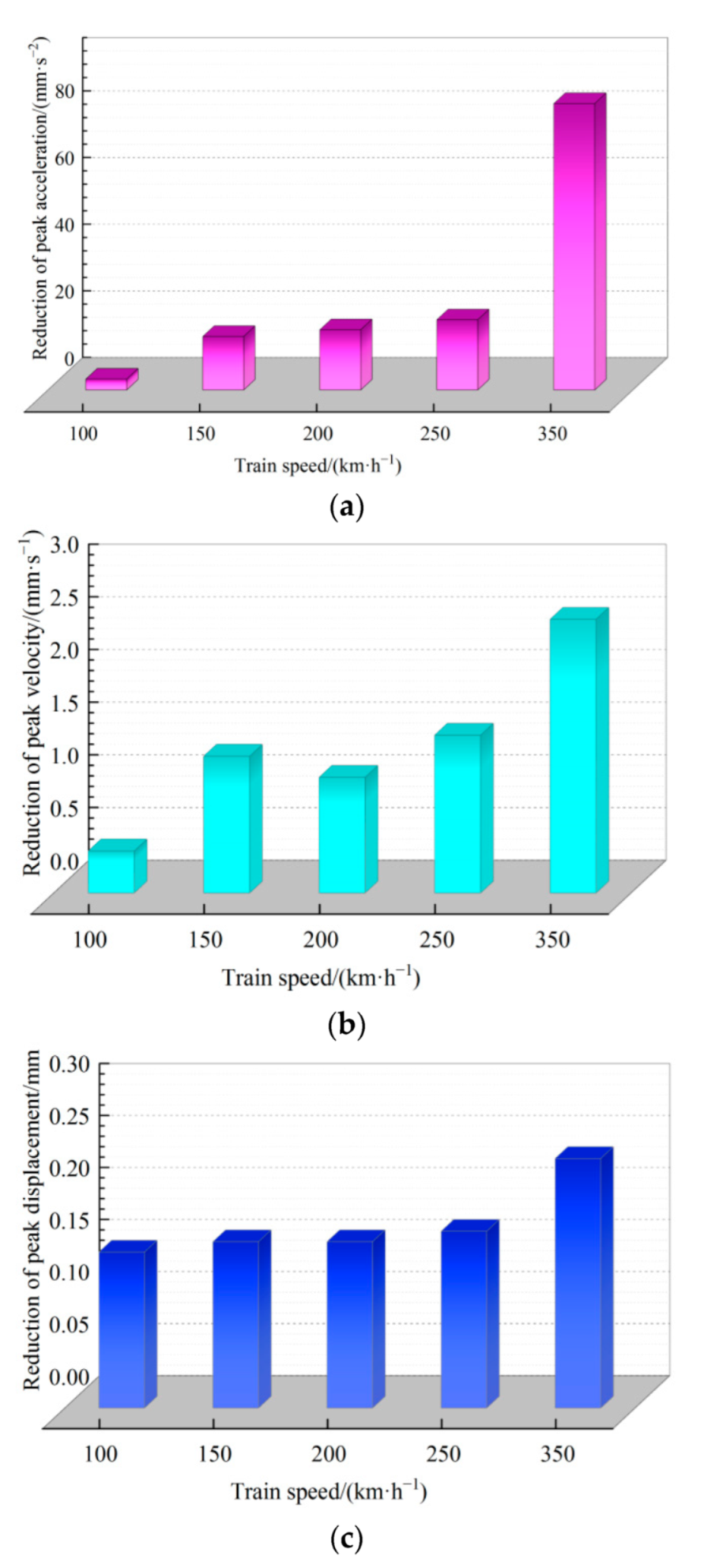
When the train speed is 100 km/h, the peak vibration acceleration, peak vibration velocity, and peak vibration displacement inside the foundation from the roof to the floor of the tunnel are reduced by 3.3 mm·s−2, 0.4 mm·s−1 and 0.15 mm, with a reduction of 28%, 26%, and 19%, respectively. When the train speed increased to 350 km/h, each dynamic response index was reduced by 86 mm·s−2, 2.6 mm·s−1, and 0.24 mm, respectively, with a reduction of 31%, 29%, and 23%. In order to show this change feature more intuitively, the reduction of the dynamic response indexes from the tunnel roof to the tunnel floor under different train speeds are shown in Figure 14. With the increase in train speed, each dynamic response index decreases with the increase in distance from the ground surface and pile, and the proportion and amplitude of the decrease all increase. The reduction of the peak vibration acceleration increases most significantly, from 3.3 mm·s−2 to 86 mm·s−2, an increase of 26 times. The impact of the tunnel structure on the attenuation of the dynamic response induced by moving train loads within the pile-soil foundation becomes more evident with the increase in train speed.

Figure 14.
Reduction in dynamic response indexes from tunnel roof to tunnel floor. (a) Peak vibration acceleration. (b) Peak vibration velocity. (c) Peak vibration displacement.
4. Conclusions
In this work, a combination of a model test and numerical simulations is used to reveal the dynamic response characteristics of a pile-soil composite foundation with an adjacent tunnel, using peak vibration acceleration, peak vibration velocity, and peak vibration displacement as evaluation indexes. The conclusions can be summarized as follows:
- (1)
- For the model test and FE simulation, the peak acceleration is at maximum at the ground surface when the train load is applied. The peak acceleration inside the foundation decreases with the increase in the distance from the ground surface and the pile and decreases significantly at the buried depth of the tunnel. The dynamic response of the tunnel lining near the vibration source is significantly greater than that of the other side, and the adjacent tunnel has an obvious vibration isolation effect.
- (2)
- When the moving train load is applied, the distribution characteristics of peak vibration acceleration, peak vibration velocity, and peak vibration displacement are similar. The dynamic response indexes of the ordinary pile-ground foundation vary less. Due to the superposition effect of the pile group, the dynamic response indexes show a “wavy” distribution with the increase in the horizontal distance from the pile. When there is an adjacent tunnel, the dynamic response indexes increase significantly, and the largest increases are 142%, 58%, and 41% at the buried depth of the tunnel roof, respectively. The dynamic response indexes between the adjacent tunnel and the pile are characterized by a monotonic distribution and decrease with increasing distance from the pile.
- (3)
- According to the security control thresholds of the peak vibration velocity of the underground structure, the foundation within 3.6 m from near pile is in the dangerously affected zone at the burial depth of tunnel, the foundation 3.6~11.4 m away from the pile is in the strongly affected zone, and the foundation outside 11.4 m from pile is in the weakly affected zone. Similar engineering cases can refer to this method to evaluate the impact due to moving train loads and determine whether vibration damping measures are required.
- (4)
- When there is an adjacent tunnel, the dynamic response of the pile-soil foundation is positively correlated with the increase in the train speed under the moving train loads and the dynamic response indexes increase the most at the surface. With the increase in train speed, the impact of the tunnel structure on the attenuation of the dynamic response induced by moving train loads within the pile-soil foundation becomes more evident, especially the peak vibration acceleration.
The conclusions drawn from the study of the dynamic response of the pile-soil foundation with the adjacent tunnel under high-speed train load have certain engineering application value for similar projects. However, there are still some problems to be further studied: the influence of different geological conditions and structural materials on the dynamic response needs to be further studied. The vibration isolation measures that may be adopted in practical engineering have a certain impact on the final results.
Author Contributions
Q.X.: methodology, writing–original draft. Y.Z.: conceptualization, funding acquisition, writing–review and editing. S.X.: investigation, software. H.F.: funding acquisition, project administration. D.W.: investigation. C.W.: data curation. M.Z.: data curation. D.X.: visualization. Y.L.: funding acquisition, resources. All authors have read and agreed to the published version of the manuscript.
Funding
This study was financially supported by the National Natural Science Foundation of China, grant number 52178391, National Natural Science Foundation for Young Scientists of China, grant number 52108378, Young Elite Scientists Sponsorship Program by CAST, grant number 2021QNRC001, S & T program of Hebei Province in China, grant numbers 21375403D and 20375410D, and the Natural Science Foundation of Hebei Province in China, grant number E2020210017. This support was greatly appreciated.
Institutional Review Board Statement
Not applicable.
Informed Consent Statement
Not applicable.
Data Availability Statement
Some or all data, models, or code that support the findings of this study are available from the corresponding author upon reasonable request.
Conflicts of Interest
The authors declare no conflict of interest.
References
- Ding, Z.; Liao, M.; Xiao, N.; Li, X. Numerical analysis of the seismic response of tunnel composite lining structures across an active fault. Adv. Mater. Sci. Eng. 2021, 2021, 1–12. [Google Scholar] [CrossRef]
- Fu, Q.; Yuan, J. Experimental and numerical study of the dynamic response of xcc pile–raft foundation under high-speed train loads. Appl. Sci. 2021, 11, 9260. [Google Scholar] [CrossRef]
- Liu, K.; Su, Q.; Ni, P.; Zhou, C.; Zhao, W.; Fei, Y. Evaluation on the dynamic performance of bridge approach back filled with fibre reinforced lightweight concrete under high-speed train loading. Comput. Geotech. 2018, 104, 42–53. [Google Scholar] [CrossRef]
- Yang, W.; Deng, E.; Shi, C.; Liu, N.; Fei, R.; Yue, H. Lining fatigue test and influence zoning of tridimensional cross-tunnel under high-speed train loads. Appl. Sci. 2020, 10, 5694. [Google Scholar] [CrossRef]
- Zhang, X.; Zhao, C.; Zhai, W. Importance of load frequency in applying cyclic loads to investigate ballast deformation under high-speed train loads. Soil Dyn. Earthq. Eng. 2019, 120, 28–38. [Google Scholar] [CrossRef]
- Liu, C.; Tang, Q.; Wu, B.; Wan, Q.; Ye, Y. Dynamic response of a heavy-haul railway tunnel’s bottom structures in hard rock. Appl. Sci. 2022, 12, 5721. [Google Scholar] [CrossRef]
- Yi, H.; Qi, T.; Qian, W.; Lei, B.; Pu, B.; Yu, Y.; Liu, Y.; Li, Z. Influence of long-term dynamic load induced by high-speed trains on the accumulative deformation of shallow buried tunnel linings. Tunn. Undergr. Space Technol. 2019, 84, 166–176. [Google Scholar] [CrossRef]
- Yang, W.; Zhang, C.; Liu, D.; Tu, J.; Yan, Q.; Fang, Y.; He, C. The effect of cross-sectional shape on the dynamic response of tunnels under train induced vibration loads. Tunn. Undergr. Space Technol. 2019, 90, 231–238. [Google Scholar] [CrossRef]
- Yang, W.; LI, L.; Shang, Y.; Yan, Q.; Fang, Y.; He, C.; Xu, Z. An experimental study of the dynamic response of shield tunnels under long-term train loads. Tunn. Undergr. Space Technol. 2018, 79, 67–75. [Google Scholar] [CrossRef]
- Gu, L.; Ye, G.; Bao, X.; Zhang, F. Mechanical behaviour of piled-raft foundations subjected to high-speed train loading. Soils Found. 2016, 56, 1035–1054. [Google Scholar] [CrossRef]
- Niu, T.; Liu, H.; Ding, X.; Zheng, C. Model tests on XCC-piled embankment under dynamic train load of high-speed railways. Earthq. Eng. Eng. Vib. 2018, 17, 581–594. [Google Scholar] [CrossRef]
- Tang, Y.; Xiao, S.; Yang, Q. Numerical study of dynamic stress developed in the high speed rail foundation under train loads. Soil Dyn. Earthq. Eng. 2019, 123, 36–47. [Google Scholar] [CrossRef]
- Shen, Y.; Xu, H.; Tao, M.; Wang, B.; Song, S. Settlement of soft clay subgrade under coupled effects of vibration frequency and dynamic stress ratio caused by high-speed train loads. Soil Mech. Found. Eng. 2017, 54, 87–96. [Google Scholar] [CrossRef]
- Dong, J.; Wu, Z.; Li, X.; Chen, H. Dynamic response and pile-soil interaction of a heavy-haul railway embankment slope reinforced by micro-piles. Comput. Geotech. 2018, 100, 144–157. [Google Scholar] [CrossRef]
- Li, H.; Liu, S.; Tong, L. A numerical interpretation of the soil-pile interaction for the pile adjacent to an excavation in clay. Tunn. Undergr. Space Technol. 2022, 121, 104344. [Google Scholar] [CrossRef]
- He, S.; Lai, J.; Li, Y.; Wang, K.; Zhang, W. Pile group response induced by adjacent shield tunnelling in clay: Scale model test and numerical simulation. Tunn. Undergr. Space Technol. 2022, 120, 104039. [Google Scholar] [CrossRef]
- Li, H.; Tong, L.; Liu, S. Multistage-based evaluation of tunnelling effects on the skin friction of adjacent building piles in layered media. Structures 2021, 32, 96–105. [Google Scholar] [CrossRef]
- Li, Y.; Zhang, W. Investigation on passive pile responses subject to adjacent tunnelling in anisotropic clay. Comput. Geotech. 2020, 127, 103782. [Google Scholar] [CrossRef]
- Lueprasert, P.; Jongpradist, P.; Jongpradist, P.; Suwansawat, S. Numerical investigation of tunnel deformation due to adjacent loaded pile and pile-soil-tunnel interaction. Tunn. Undergr. Space Technol. 2017, 70, 166–181. [Google Scholar] [CrossRef]
- Yang, W.; Cui, G.; Xu, Z.; Yan, Q.; He, C.; Zhang, Y. An experimental study of ground-borne vibration from shield tunnels. Tunn. Undergr. Space Technol. 2018, 71, 244–252. [Google Scholar] [CrossRef]
- Yang, W.; Hussein, M.F.M.; Marshall, A.M. Centrifuge and numerical modelling of ground-borne vibration from an underground tunnel. Soil Dyn. Earthq. Eng. 2013, 51, 23–34. [Google Scholar] [CrossRef]
- Yang, W.; Hussein, M.F.M.; Marshall, A.M.; Cox, C. Centrifuge and numerical modelling of ground-borne vibration from surface sources. Soil Dyn. Earthq. Eng. 2013, 44, 78–89. [Google Scholar] [CrossRef]
- Yang, W.; Zou, T.; Tu, J.; Gu, X.; Liu, Y.; Yan, Q.; He, C. Analysis of dynamic response of horseshoe cross-section tunnel under vibrating load induced by high-speed train. China Rock Soil Mech. 2019, 40, 3635–3644. (In Chinese) [Google Scholar]
- Chen, J.; Meng, D.; Li, J. Research on the dynamic response of prestressed pipe pile supported and geogrid reinforced subgrade. Chin. J. Undergr. Space Eng. 2020, 16, 679–686. (In Chinese) [Google Scholar]
- Lysmer, J.; Waas, G. Shear Waves in Plane Infinite Structures. J. Eng. Mech. Div. 1972, 98, 85–105. [Google Scholar] [CrossRef]
- Chen, C.; Cao, R.; Zhao, Y.; Kou, W.; Zhang, X. Simulation analysis on high-speed railway structural dynamic response under the action of train load when metro tunnel in minimal spacing under high-speed railway. China Urban Mass Transit 2020, 23, 31–36. (In Chinese) [Google Scholar]
- Shen, Y.K. Study on The Propagation Laws of Subway-Induced Vibration and Isolation or Reduction Methods of Building Vibration. Ph.D. Thesis, Tongji University, Shanghai, China, 2015. (In Chinese). [Google Scholar]
- Zhang, H.; Liu, W.; Liu, W.; Jia, Y. Study on standard for assessing effects on structures of metro line 2 due to vibrations induced by underground trains on diameter line in Beijing. China Tunn. Constr. 2007, 27, 93–97. (In Chinese) [Google Scholar]


Publisher’s Note: MDPI stays neutral with regard to jurisdictional claims in published maps and institutional affiliations. |
© 2022 by the authors. Licensee MDPI, Basel, Switzerland. This article is an open access article distributed under the terms and conditions of the Creative Commons Attribution (CC BY) license (https://creativecommons.org/licenses/by/4.0/).