1. Introduction
The heating of biological tissue with inserted gold nanoparticles (GNPs) by radiofrequency (RF) electromagnetic radiation is an important phenomenon with potential to be used as a non-invasive method to treat cancer [
1,
2]. The method relies on the cancer cells’ property to intake an abnormal amount of nutrients. If GNPs are coated with suitable nutrient ligands, they can be taken into the cancer cells with high concentration, while their concentration in normal cells remains low [
3,
4,
5]. Consequently, the temperature of cells with high GNP concentration will increase to such levels to cause the death of such (cancer) cells under exposure of an externally applied RF field. This effect occurs at temperatures between 43 and 49 °C [
6,
7,
8,
9]. Furthermore, normal cells recover faster than cancer cells when exposed to heat, due to having more blood flow and hence greater heat dissipation [
10]. In addition, hyperthermia in this context seems to actually enhance the immune system instead of harming it [
9]. The ligand shells also provide the GNPs with a net charge [
11,
12]. The size of the GNPs cannot be larger than 5 nm in order for them to pass through the kidneys [
13].
While the physical mechanism behind the heating of GNPs under optical frequencies is well understood to be caused by localized surface plasmon resonances [
14,
15,
16], the mechanism behind RF heating of GNP-fed biological tissue has, however, been a subject to extensive investigation. It is established that the main source of cell heating is the electrophoretic acceleration of charged particles, while Joule and inductive heating are found to be negligible [
2,
11,
17]. The applied RF radiation drives the GNPs into resonant oscillation leading to dielectric losses associated with the electrophoretic current. A challenge for the proposed medical application is that absorption occurs in both the target cancer cells and in the background media. This was investigated in previous work [
18,
19] for a spherical/ellipsoidal suspension of GNPs in a spatially unlimited system. An alternative approach is to isolate the system in a waveguide setting as shown in more recent work [
20,
21] for the purpose of increased control of the environment and as a practical comparison to future experimental measurements.
The overall objective of the research reported in the present paper is to develop theoretical and practical techniques to identify GNP model parameters, and obtain optimal electrophoretic resonance in a thin GNP-treated cell substrate inserted in a waveguide. This is shown in the overview in
Figure 1. Thereafter, the potential to achieve sufficient local heating resonance inside the target tumor cells (quantified by the absorption cross-section) to be able to destroy them through heat, with no adverse effect on the surrounding normal tissue, will be evaluated. With this in mind, in [
20,
21] one of the present authors developed a general analytical framework for a graded waveguide structure in which a thin dielectric layer surrounded by some background material is described as a stratified medium, as in
Figure 2. The work supports both dispersive and lossy material parameters, and the total scattering matrix can be obtained without the use of mode matching and cascading techniques. With the two media described by a single, effective permittivity function, there is no need for boundary conditions between the media. Consequently, only a single solution of Maxwell’s equations is needed to obtain transmission, reflection and absorption parameters needed to assess the feasibility of the proposed heating method. The graded waveguide description is motivated by its ease of extracting reflection, transmission, and absorption coefficients, relevant for future measurement setups as well as current numerical model setups. Furthermore, there is always a transition region between biological tissues, and no sharp interfaces. The medical application is thus graded by nature.
The general exact analytical fomulas for transmission, reflection, and absorption coefficients in waveguide settings with inserted GNP-substrates are known from our previous work [
20,
21]. These general fomulas are further developed here to be readily applicable to the calculation of absorption coefficient within the inserted lossy layer only, quantifying the absorption in the GNP-fed cancer tissue. In doing so, a theoretical scaling factor is added as an extension to the theory developed in [
20]. The scaling factor is valuable for both the analytical solution and the numerical results when one wants to investigate losses within the thin layer only and eliminate the smaller and unessential absorption in the surrounding lossy medium. This is particularly handy for numerical methods that use scattering parameters, where distinguishing between absorption regions is difficult when the ambient medium is lossy. Although the general analytical results are known, it is of interest to study these analytical solutions in more detail and to compare them to state-of-the-art numerical simulations to confirm their usefulness and prediction power. We therefore compare the numerical simulation results for power transmission, reflection and absorption coefficients, obtained using COMSOL Multiphysics software, with the corresponding results obtained from the modified exact analytic fomulas. The study includes both a simple example of constant complex permittivities, and a more realistic example where a dispersive model of permittivity is used to describe human tissue and the electrophoretic motion of charged gold nanoparticles.
Thus, in this paper, we developed a numerical approach to the graded waveguide model using COMSOL Multiphysics, a modeling software based on the finite element method. The numerical examples in previous work on graded waveguides [
20,
21] used constant permittivities with respect to frequency, and their magnitudes were chosen with no particular application in mind. In [
18,
19], material values were chosen based on metal particles immersed in saline water, and with no dispersion. In the present paper, we also include a more realistic numerical example based on dispersive permittivity describing actual human tissue, as well as the dispersive permittivity describing the thin layer with a concentration of GNPs absorbed in such a tissue where their electrophoretic particle acceleration is described by the Drude model.
Due to the similar mathematical notation and descriptions, it is important to particularly emphasize the novelty of the present work, as compared to our previous publications [
20,
21,
22]. In [
20], the general theory of TE-wave propagation in the waveguide setting was developed for the first time. It constitutes an important mathematical basis for the present work. However, the work reported in [
20] did not include any energy considerations such as, e.g., energy transmission, reflection and absorption, and did not consider the problem of extracting the energy absorption in the GNP-fed thin layer from the absorption in the rest of the infinite waveguide. It does not consider the more realistic finite waveguide either. Furthermore, no particular dispersion models for the GNP-fed target layer and the surrounding tissue were considered, and there were no attempts to numerical verification. These issues are essential for any future simulations and measurements. The work reported in [
21] addressed some of these issues. It generalized the results reported in [
20] to both transverse electric (TE) and transverse magnetic (TM) polarization, and included a first attempt to provide energy considerations. However, it still does not properly consider the problem of extracting the energy absorption in the GNP-fed thin layer from the absorption in the rest of the realistic finite waveguide, and it does not include any dispersion models for the GNP-fed target layer and the surrounding tissue. In the short conference paper [
22], the first attempt to numerically consider the problem of extracting the energy absorption in the GNP-fed thin layer from the absorption in the rest of the infinite waveguide was made. However, in [
22], no resolution of the issue of properly considering the problem of extracting the energy absorption in the GNP-fed thin layer from the absorption in the rest of a realistic finite waveguide is provided, and no realistic dispersion models for the GNP-fed target layer and the surrounding tissue are considered. In the present paper, all the above-mentioned issues are finally resolved. Thus, the present paper provides important and novel tools, that are essential for future practical validations and measurements.
Notation and Conventions
The present paper assumes electromagnetic fields oscillating proportional to . This time convention implies that the imaginary part of the relative permittivity must be negative for a passive dielectric material. The vacuum wavenumber is defined by where and denotes the permeability and permittivity in vacuum, respectively. The transverse wavenumber is denoted by and longitudinal wavenumber is defined by . The real and imaginary parts of any complex number are, respectively, denoted by and .
2. Wave Propagation through a Graded Layer
The geometry of the problem is presented in
Figure 2. The surrounding non-magnetic lossy waveguide medium is described by the complex relative permittivity
. The thin lossy non-magnetic layer, inserted about
z = 0, is described by the complex relative permittivity
. In a previous study by one of the present authors [
20], it was found that a homogeneous straight waveguide medium with a single thin layer can be described as a stratified medium with frequency-dependent permittivity
being a function of the
z-coordinate (waveguide axis direction).
The two different media in the waveguide, as shown in
Figure 2, can be modeled as a single stratified medium with a spatially dependent permittivity
, where
denotes the relative permittivity, given as a function of the waveguide axis direction
where
represents the thickness of the inserted dielectric layer around the plane
z = 0. Far away from the thin dielectric layer (
) the function (
1) behaves as follows
while at the center position of the thin dielectric layer (
) the relative permittivity (
1) becomes
This asymptotic behavior ((
2) and (
3)) is in agreement with the geometry of the problem shown in
Figure 2. A geometry with a very thin layer and rapid smooth transition from
to
and back to
, is obtained in the limit
. The waveguide description presented here is a general theory, where any permittivity model can be employed as long as it satisfies the Kramer-Kronig relations. Two examples of permittivity models [
18,
19,
23] for the two dispersive media,
and
, are given in the next sections of this paper. To describe the wave propagation in a waveguide, without field sources inside (
,
), we use the following wave equations [
20] for the electric and magnetic fields for TE-waves (with
)
Here we solve the first of Equations (
4) for the electric field
, whereby the magnetic field
is readily obtained from the first of Maxwell’s equations, i.e., using
Thus, the first of Equations (
4) with
is equivalent to two scalar equations, both of which are of the form
In the special case of a rectangular waveguide with cross-sectional lengths
and
, we then obtain the overall expressions for the two electric field components in the form
where
A is a constant proportional to the incident electric field amplitude
, and
is the transmission coefficient which will be given below. Furthermore,
is the ordinary Gaussian hypergeometric function [
24]. In (
7) and (
8), several short-hand notations are introduced, as also seen in [
20,
21], and are defined as follows
with
where
is the
z-component of the wave vector of the asymptotic waves for
, and the transverse wavenumber
is given by
for a rectangular waveguide. Based on the above solutions, from [
20], the general expressions for the transmission coefficient (
) and the reflection coefficient (
), are
where
is the Gamma function [
24]. In lossless media, the power reflection coefficient is given by
and the power transmission coefficient is given by
. These coefficients satisfy
, since there is no absorption of energy in the two media.
Power Considerations with Losses
For lossy media,
is nonzero, such that
, quantifies the absorption (electromagnetic energy loss) in the entire waveguide. Plotting this quantity, one can investigate the dependence of the absorption on frequency and on layer size
. In order to study the absorption in the dielectric layer only, we need to calculate the power reflection coefficient (
) and power transmission coefficient (
) over the layer (
). In order to exclude the losses in the surrounding medium, we use the following exact analytical fomulas [
22]
where we have defined an auxiliary scale factor
by
where
is the Gauss hypergeometric function and Equation (
10) can be used to relate
p to
. If we want to study the losses, i.e., the absorption, in any finite part of the waveguide, we need to calculate the power reflection coefficient (
) and power transmission coefficient (
) over some arbitrary layer (
), where
m is a number that defines how large is the studied part in the units of
. It is not necessarily an integer, but can be any fraction. We then obtain the generalized fomulas
where we have defined
When performing the analytical analysis of reflection, transmission and absorption, Equation (
14) is sufficient as a scale factor since one is free to assume an infinitely long waveguide. When analyzing waveguides of finite length, which is required by numerical methods and experimental setups, being by necessity of finite length, one can use both (
14) and the generalization (
16) to relate the losses in the thin layer of thickness
to the losses in a finite waveguide with length
, which in turn can be seen as a section of an infinite waveguide. From the above fomulas we readily see that the relative scale factor
is given by
This is a rather complex scale factor but it is exactly equal for both the power transmission and power reflection coefficients.
4. The Finite Element Model
A three-dimensional model of the waveguide illustrated in
Figure 2, with a rectangular cross-section, was developed in COMSOL Multiphysics. Material properties were described by the spatial function (
1) with complex permittivities
and
. The waveguide walls acted as perfect electric conductors. Rectangular ports at either end of the waveguide excite and absorb the propagating modes within, and were backed by perfectly matched layers. The waveguide was given a finite length sufficiently larger than
, so that the ports were located far away from the layer, in the limit (
2). The reflection (
) and transmission (
) power coefficients were calculated using the scattering parameters obtained from COMSOL at the reflection (
) and transmission (
) ports, which were then multiplied by the scale factor (
17) to account for the ambient losses
, where the number
m describes the ratio of waveguide length (i.e., distance between the two ports) to thin layer length
.
The simulations presented in this paper were run on a computer equipped with an Intel i7-10700K processor with 64 GB RAM, running on Windows 10. In the case of a waveguide length of 17 cm, the solution time was 1 s for GHz and 16 s for GHz.
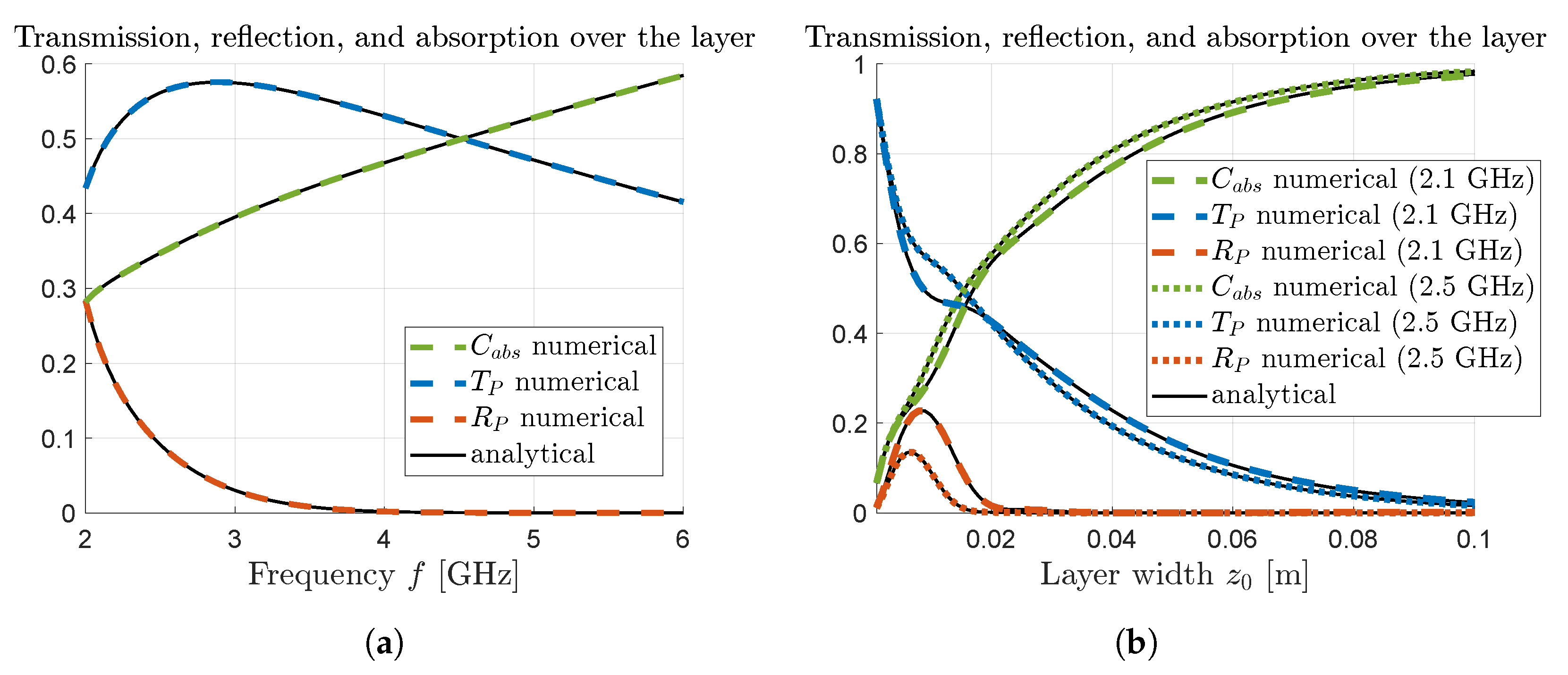
6. Discussion
From the results presented in
Figure 3 and
Figure 4, we see that there is an excellent agreement between the numerical results, obtained using the COMSOL simulation software, and the analytical results obtained using (
13).
In the dispersive example above, we emphasize that the electrophoretic Drude description (
19) involves several design parameters, e.g., the molecular composition of ligands affecting their electron count
, and it is left for future work to investigate the feasibility of the medical application in regards to these parameters. Although the material properties chosen in the dispersive study are realistic themselves, their combination do not necessarily represent the description of the medical application. A step in this direction could be to replace
to describe a malignant breast tissue instead of normal breast tissue. The difference in microwave properties between the two have shown that malignant tumor is estimated at almost 5–10 times larger [
29], which will affect its response to electromagnetic radiation. Additionally, with cancerous tissue having significantly higher water content than normal tissue, and adipose tissue such as breast fat having reduced water content, the motion of GNPs in their host medium will be affected via the friction constant
. As such, both Drude parameters and the layered composition of involved materials will be tuned further in order to achieve specific goals such as maximum absorption resonances for the medical application, which will be the objective of our continued efforts.
Compared to many other tissues in the human body, breast fat and other adipose tissues is less absorbing due to lower water content, where the imaginary part of the permittivity has values around 0.8–1.5 in the low GHz range. Even so, over the entire waveguide (17 cm in the dispersive example) at most
is reflected and a fourth of that is transmitted via the thin layer, as seen in
Figure 5a. The remainder is absorbed throughout the surrounding tissue as well as the thin layer. Comparing this to the result in
Figure 4 it is clear that the relative scale factor (
17) is valuable in extracting meaningful information on the response within the thin layer only.


