1. Introduction
Aero-engine casing is a kind of thin-walled rotary part for which service stability is critical to service safety and engine reliability. Severe deformation often occurs in the machining of an aero-engine casing part due to the influence of both initial residual stress and machining residual stress, which negatively impacts the performance and service life of an aero-engine [
1,
2]. As deformation force is an important physical quantity associated with deformation, its monitoring can provide useful information for deformation control. With the material being removed during machining, the balance of residual stress is broken, which leads to part deformation. While under the fastened state, the deformation of a part is restricted within the limits of the fixtures, and the residual stress is balanced by the clamping force. The component in the clamping force resulting from the unbalanced residual stress is commonly referred to as the deformation force, which can be used to represent the state of unbalanced residual stress inside the workpiece [
3]. Due to the structural characteristics of aero-engine casings, the most useful deformation force for deformation control of an aero-engine casing is in the radial direction. By integrating force sensors into the fixture, the deformation force can be monitored. The radial deformation force of the aero-engine casing can be monitored by introducing force sensors in the radial auxiliary supports.
Past research results notwithstanding, the accurate acquisition and monitoring of deformation force during the machining process of an aero-engine casing remains a challenging problem. As the auxiliary supports of aero-engine casing fixtures acting on the sidewalls can only provide a one-way support force, the part and fixtures may be separated from each other during machining, which makes monitoring the deformation force impossible. In this paper, aiming to prevent the fixture and the part from separating, a deformation force monitoring method for aero-engine casing based on the idea of applying a pre-support force is proposed. However, as the deformation cannot be determined in advance, the deformation force monitoring method based on relying on a pre-support force is faced with the issues of low monitoring success rate and the clamping deformation that affects the machining accuracy. To solve the above problems, this paper offers the following two innovations: (1) a set of sophisticated clamping devices with force sensors are specifically developed; and (2) the pre-supporting force is decided by an equivalent flexibility and a probabilistic model which predicts the subsequent deformation force based on the preceding deformation forces. In addition, considering the modeling and measurement errors, fusing filtering algorithms to neural networks [
4,
5,
6] can remove data noise and restore the original data, which can improve the performance of the model. Therefore, the Kalman filter algorithm is applied to reduce the modeling and measurement errors.
2. Related Works
Process monitoring is critical for machining quality control, especially for the machining of high-precision or difficult-to-machine parts. The related works are reviewed in the following in four aspects: machining status monitoring, clamping force adjustment, the application of probabilistic model in manufacturing, and the combination of model-based methods and data-driven methods.
2.1. Machining Process Monitoring
Many studies aimed at improving the accuracy of part machining based on the monitoring of a machining process and adjusting certain process parameters have been performed. Chen et al. [
7] proposed a deformation error compensation method based on deformation monitoring. Zhao et al. [
8] presented an online deformation prediction method based on applying recurrent neural networks to the monitored deformation data. Wang et al. [
9] proposed an allowance compensation approach based on an online measuring method for adaptive compensation of cutting depth in the finishing stage of machining. Yoshioka et al. [
10] offered a method to improve part surface quality by monitoring the distance between the tool and workpiece. In the realm of additive manufacturing, which is being used more frequently in aerospace manufacturing industry [
11], Francis et al. [
12] proposed an online deformation prediction method based on temperature monitoring for laser melting additive manufacturing. As the clamping force data [
3] during a machining process reflects the potential deformation, Oscar et al. [
13] developed an intelligent fixture for aero-engine casings, which is able to monitor the clamping force on the lower end face and automatically adjust the clamping status. Li et al. [
14,
15,
16,
17] proposed several methods to control the machining deformation for aerospace structural parts by means of pre-deformation and adjusting the machining sequence. Based on monitoring the deformation force, Zhao et al. [
3] proposed a data-driven deformation prediction method that can online-predict the machining deformation.
The aforementioned studies offer a wide range of solutions to machining process monitoring for different kinds of parts, especially large structural parts, with respect to deformation monitoring. However, for parts like aero-engine casings that have unique structural characteristics, the development of a more advanced deformation force monitoring systems and the associated methodologies is still necessary. That is the main objective of this paper.
2.2. Clamping Force Adjustment
Deformation force is measured by evaluating variations in the clamping force. An improper clamping force can cause severe clamping deformation and affect the machining accuracy. Hence, it is important to control the clamping force to ensure the machining quality. Chen et al. [
18] proposed a method to optimize both the acting position and amount of clamping force, aiming at reducing the machining deformation and making the deformation distribution more uniform. Zhang et al. [
19] optimized the clamping force and fixture layout for assemblies of thin-walled parts to reduce the gap elimination rate and the total clamping force. Using the genetic algorithm and the finite element method, Huang et al. [
20] optimized the fixture layout and clamping force to improve the clamp positioning accuracy. Cioată et al. [
21] proposed a finite element method-based approach to determine the clamping layout and clamping force to minimize the displacement of selected edges and minimize the equivalent force of the workpiece. Zhang et al. [
22] proposed a method to control the machining deformation of an aero-engine blade by adaptively adjusting the fixture.
The aforementioned studies improve the manufacturing accuracy by optimizing the clamping force. However, they only consider the effect of clamping deformation; more specifically, they mainly consider the impact of structural stiffness when deciding the clamping force, while for a better monitoring of deformation force, the impact of residual stress should also be considered.
2.3. Application of Probabilistic Model in Manufacturing
As any data collected under certain circumstances should obey a certain distribution, probabilistic models are powerful tools for estimating the parameters of a distribution. Common probabilistic models include the Bayesian analysis, the Gaussian process regression, and the Hidden Markov Model. Bayesian analysis is a method for calculating hypothetical probabilities according to the assumed prior probabilities, the probability of observing different data given the assumptions, and the observed data itself. It synthesizes the prior information with the sample information and infers the unknown parameters by the Bayesian formula. Li et al. [
23] presented a deformation prediction model based on the Bayesian network and the prediction–uncertainty measurement method to analyze the effect of different influencing factors on machining-deformation uncertainty. Yuan et al. [
24] developed a data-driven Bayesian learning method to predict the deformation of skinned parts online and compensate for the predicted deformation using a bimodal predictive controller. The Bayesian approach has a greater advantage in dealing with some problems with prior knowledges, but not for problems without one. Zhou et al. [
25] designed a special tool holder for tool condition monitoring and used a Hidden Markov Model to diagnose the tool wear status. Tao et al. [
26] proposed a hybrid framework based on LSTM and the Hidden Markov Model to calculate the average wear and the remaining service life of a cutting tool, as well as the associated confidence intervals. Some scholars also suggested the use of nonparametric models, such as Gaussian regression and mixed Gaussian models using Gaussian distribution prior to the analysis of data. Wu et al. [
27] proposed an adaptive variational inference Gaussian mixed regression (AVIGMR) model for gear machining error prediction. Wang et al. [
28] gave a 3D printing thermal deformation prediction method based on a Gaussian mixed model for compensation of deformation during processing. Javier Diaz-Rozo et al. [
29] proposed a machine tool condition monitoring method based on Gaussian dynamic probabilistic clustering.
2.4. Combination of Model-Based Methods and Data-Driven Methods
Neural network has a powerful nonlinear modeling ability and can accomplish tasks that are difficult for traditional methods. Data-based neural network modeling approaches rely heavily on data. When dealing with some practical problems, the existing prior knowledge can often be used to improve the effectiveness of the model. Merging model-based and data-driven methods is an effective way to use prior knowledge. Greydanus et al. [
30] proposed the Hamiltonian Neural Networks with knowledge of exact conservation laws, which can accelerate the training process of the model and have better generalization than a regular neural network. Yin et al. [
31] proposed the APHYNITY framework for augmenting incomplete physical dynamics. Wang et al. [
32] integrated the model-based and data-driven methods to assess and control a power system’s online frequency stability. Tan et al. [
33] proposed a hybrid physical model-based and data-driven approach for linearizing a power flow model. Although better prediction results could be obtained by the above methods, it also requires large training data. To address this issue, simulation data generated based on the mechanism model is always used to enhance the model training. Zhang et al. [
34] proposed a mold temperature distribution prediction model which uses the simulation data and the simulation error as training data, while the model also needs training or adjustment during the manufacturing process.
In another aspect, constructing a neural network based on a filtering algorithm is also a common fusion method. Input errors usually negatively affects the convergence of neural networks or lowers the effect of the model. Filtering algorithms are methods for removing data noise and restoring the original data. When the measurement variance is known, the Kalman filter can estimate the state of a dynamic system from a series of data with measurement noise. Therefore, the fusion of the Kalman filter algorithm and neural network can reduce the effect of input error. Wang et al. [
35] proposed a method to reduce the large roll motion of sailing ships which combines a Basis Function Neural Network and Unscented Kalman Filter to design a rudder roll stabilization system. Jin et al. [
36] proposed an extended Kalman filter-based artificial neural network method to eliminate the temperature effects and detect damages for structures equipped with long-term monitoring systems. Cho et al. [
37] proposed a fault detection and diagnosis method which employed a Kalman filter to estimate the condition of a blade pitch system and used an artificial neural network to diagnose a predetermined fault type. Shaukat et al. [
5] proposed a novel multi-sensor fusion algorithm for underwater vehicle localization that improves the state estimation by augmentation of the radial basis function neural network with an extended Kalman filter. Chen et al. [
4] proposed a method that applied a feed forward neural network and the extended Kalman filter to estimate the state of charge of the battery. Nguyen et al. [
38] proposed a calibration method for enhancing robot position accuracy using an extended Kalman filtering algorithm. The above existing research mainly targets data preprocessing and model training, while the Kalman filter can be used to narrow the distribution gap of the simulation data and real data, which have provided good inspiration to the authors. As already alluded to, deformation force is an important physical quantity associated with the deformation, and its monitoring can provide useful information for deformation control. Specific to aero-engine casings, due to their unique structural characteristics, the development of more advanced techniques of deformation force monitoring is called for. Therefore, in this paper, we propose a new deformation monitoring methodology specifically targeting parts like an aero-engine casing. Our methodology has several important components, such as the exertion of a pre-force of clamping, the application of powerful probabilistic models, and the use of Kalman filter, as to be presented.
3. Definition of the Problem
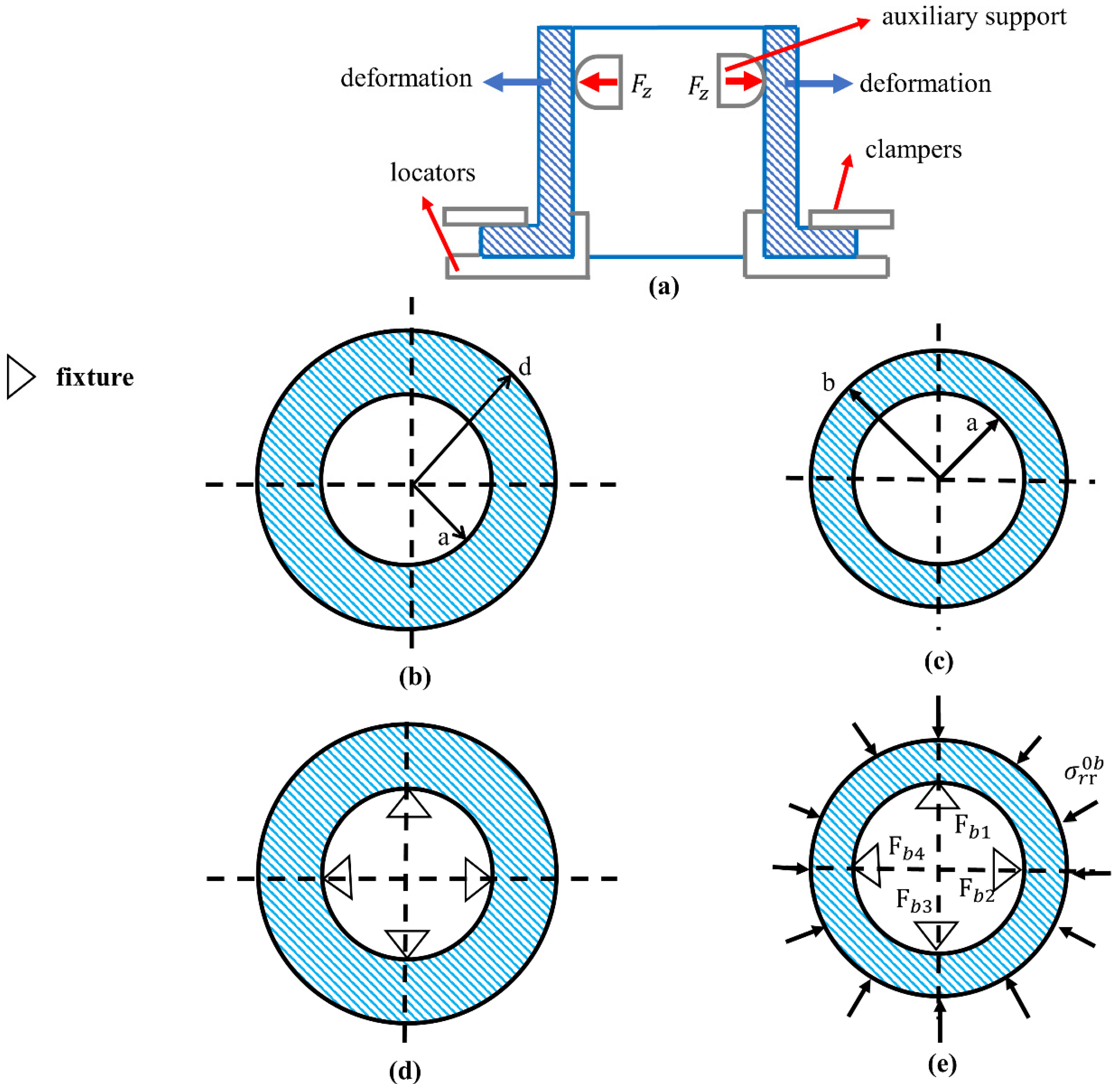
During the machining process of an aero-engine casing, the part is clamped by a set of fixtures, which in general can be divided into two kinds, i.e., one that provides the position and clamping function, and the other that is used to enforce rigidity. As shown in
Figure 1a, the positioning and clamping elements are arranged on the lower end face. Multiple supports are arranged evenly on the inside of the part to increase the stiffness of the part.
For radial deformation force monitoring, the challenging problems are the complexity of part deformation as well as the coupling effect of the change of stiffness. When the part is separated from the fixture due to deformation, it becomes impossible to monitor the change of clamping force. Therefore, it is necessary to exert an extra supporting force to maintain the contact between the part and the fixture. Obviously, the supporting force cannot be too small; lest it would be unable to monitor the change in clamping force due to the machining deformation. Conversely, it cannot be too large, as that would cause a large clamping deformation and hence affect the machining accuracy.
The part deformation caused by the pre-support force
is calculated by (1):
where
is the deformation generated by the action of all the auxiliary supports at the clamping point
,
is the pre-support force applied by the auxiliary support
, and
denotes the equivalent flexibility of the force acting normal to the clamping point
at the clamping point
.
The auxiliary supports are arranged evenly along the circumference, and to reduce the effect of uneven clamping deformation on machining, a same amount of pre-support force is applied at each auxiliary support. Therefore, (1) can be simplified to (2):
where
F is the support force applied at each clamping point,
is the equivalent flexibility, and
is the clamping deformation.
After one step of machining, the clamping force will change because of the rebalancing of the internal residual stress and the change of stiffness of the part. Therefore, the support force of each auxiliary support becomes
, and the auxiliary support still works under the conditions of (3):
The part tends to deform after machining, but the fixture constrains its deformation. The deformation relationship between the part and the fixture after the machining is given by (4):
where
is the support force at each clamping point,
is the equivalent flexibility, and
. is the clamping deformation, all after the machining.
As fixtures constrain the part deformation, the amount of part deformation
can be expressed as in (5):
According to the elastic mechanics, the deformation force can be expressed as in (6):
The delta of the support force is given as in (7):
As a result, the change of clamping force can be expressed as in (8):
where
is the equivalent flexibility of the part before machining,
is the equivalent flexibility of the machined part,
is the clamping deformation, and
is the deformation force.
In summary, the problem of calculating/monitoring the deformation force of an areo-engine casing is transformed into the problem of solving for the deformation force and the equivalent flexibility. The change of equivalent flexibility of the part can be computed by using a finite element solver [
39]. But to obtain the optimal pre-support force, the deformation force of the part at each machining step needs to be determined, as will be presented next.
4. Deformation Force Monitoring Based on Adaptive Adjustment of Clamping Force
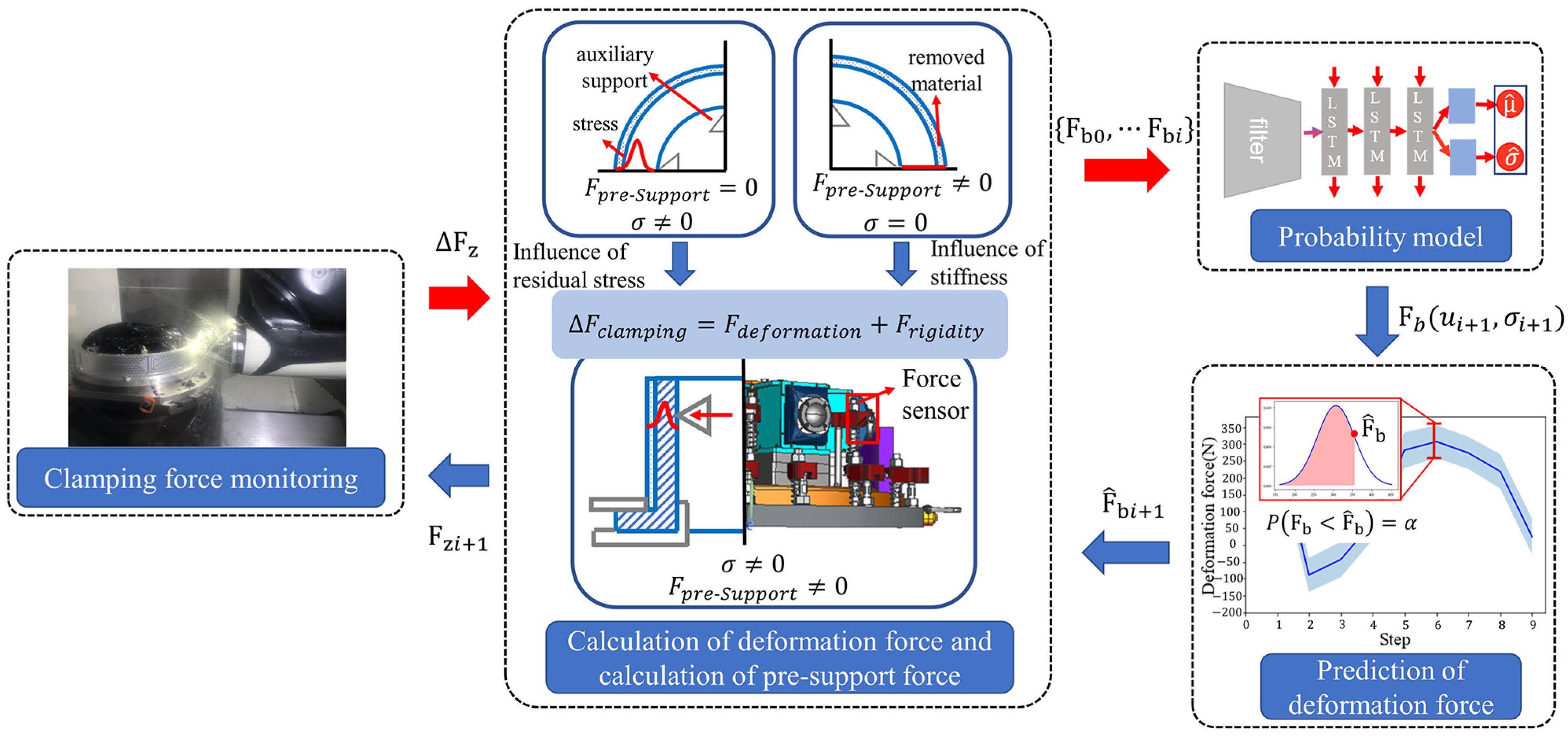
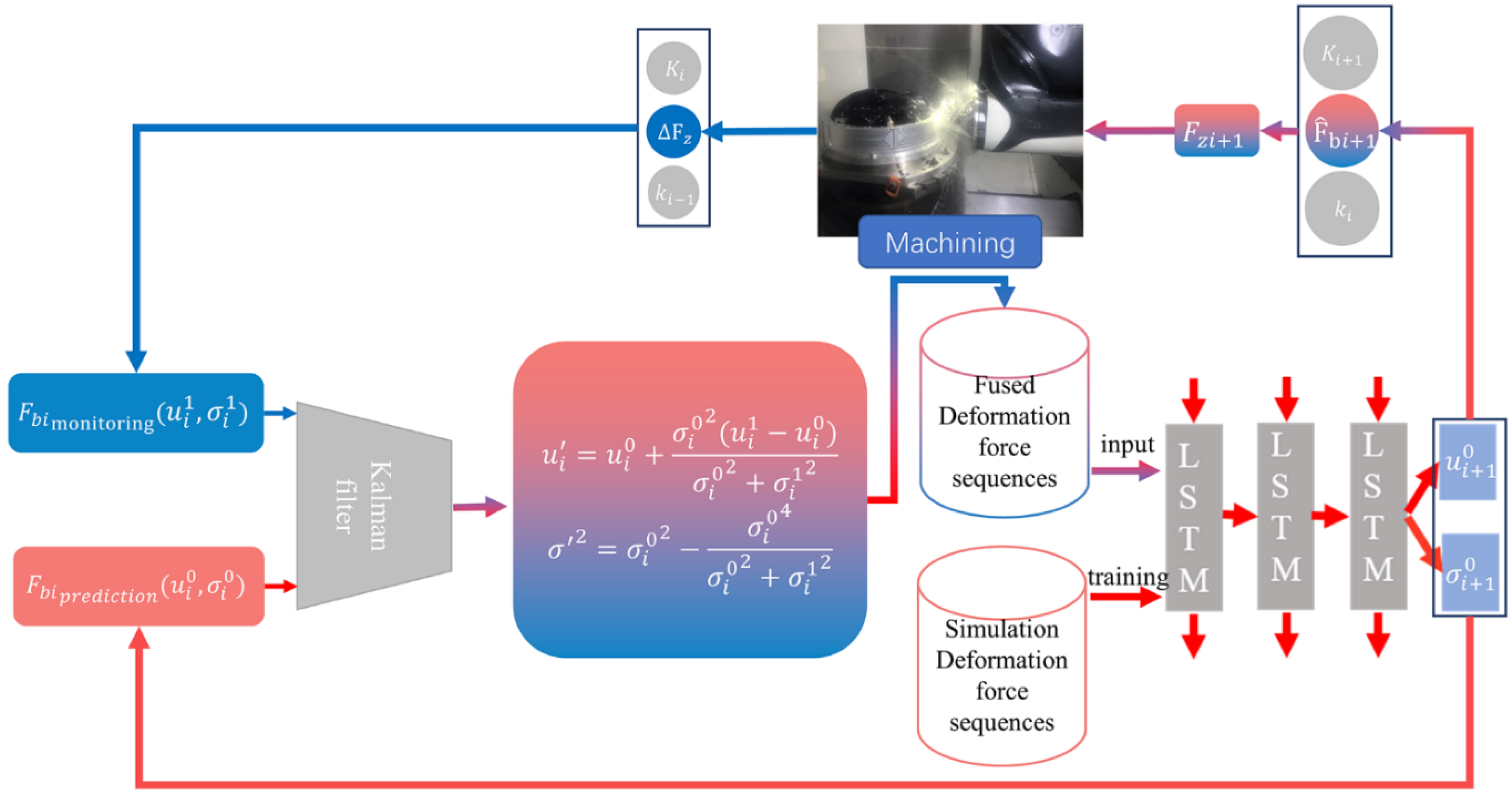
This section investigates the correlation among a deformation force sequence, which will provide a foundation for predicting the subsequent deformation forces. To improve the success rate of deformation force monitoring and reduce the influence of clamping deformation on machining accuracy, a probabilistic model for the prediction of deformation force is proposed, which combines with both the Kalman filter algorithm and a clamping force decision method based on the principle of equivalent flexibility. The entire methodology proposed in this section is shown in
Figure 2.
4.1. Correlation among a Deformation Force Sequence
The machining deformation of aero-engine casing falls into the three-dimensional elasticity category. However, the existing analytical methods are mostly 2D and hence unable to solve the problem. Our solution is to simplify the problem into a plane stress problem [
40,
41], as shown in
Figure 1b–e.
As shown in
Figure 1e, the rebalancing of residual stress can be equivalent to a uniform external pressure. According to the stress function method [
40,
41] of elasticity, the stress distribution of a rotating body subjected to a uniform external pressure is given as in (9):
where
is the residual stress distribution,
is the residual stress at
, and
,
and
are the internal stress distribution of the part after machining.
Based on the generalized Hooke’s law, the radial strain can be calculated as in (10):
where
is the Young’s modulus and
the Poisson’s ratio.
Thus, the radial strain at
can be calculated according to (11):
By definition of displacement and strain in elasticity theory, the radial displacement (deformation) can be calculated according to (12):
When the thickness of the part is small, it can be assumed that the strain of the part is constant; then (12) can be simplified as (13):
The radial deformation force can be calculated according to (14):
where
is the equivalent flexibility at the clamping point.
Since the stress distribution is not planar during the actual machining process, the strain of the part is not constant, and the part is also influenced by the positioning and clamping elements, which make the relationship between the deformation force and residual stress more complex. Nevertheless, the above equations show that the part deformation force after material removal is related to the part residual stress distribution, the part material, and the part geometry. In summary, there is a correlation among the deformation force sequence, and the subsequent deformation force can be predicted by the preceding deformation force.
4.2. Deformation Force Prediction Based on Deep Autoregressive Neural Network
To reduce the risk of supports failure after the machining and prevent excessive clamping deformation due to the application of excessive pre-support force, a probabilistic model is proposed to predict the machining deformation force, specifically targeting a part like aero-engine casing. Based on the estimated distribution parameters, a confidence level
can be selected so that
. The proposed model employs the deep autoregressive neural network [
42], which is a probabilistic model based on LSTM [
43], which can predict a probability interval.
Let
denote the value of a time series
at time
t; the objective of a probabilistic model is to establish a conditional distribution as in (15):
where
is the covariate, which is known at any time. This distribution can predict the current value of system
based on the historical data
and covariate
. The model is based on an autoregressive neural network [
44,
45] (the autoregressive recurrent network architecture). The model distribution
consists of multiple likelihood multipliers, as in (16):
where
and
is a recurrent neural network composed of LSTM units. The likelihood function
is a fixed distribution whose parameters are output from the neural network. This distribution can be selected according to the learning objective, e.g., the Gaussian distribution or Binomial distribution. Based on our past experiences, in this work the Gaussian distribution is selected, which is determined by two parameters
, where
and
are respectively the mean and variance of Gaussian distribution, and the likelihood function can be calculated as in (17):
The mean and variance of Gaussian distribution are calculated according to (18) and (19):
Finally, the model is trained by maximizing the likelihood function, as in (20):
The structure of our deformation force prediction model based on the deep autoregressive neural network is shown in
Figure 3. It takes the historical deformation force data
as input and outputs the subsequent machining step deformation force.
4.3. Optimal Estimation of Deformation Forces Based on the Kalman Filter Algorithm
In machine learning, it is usually assumed that, while the training data and the test data are independent of each other, they are identically distributed. However, the training data are derived from simulation while the model needs to be applied to real world data. We consider the difference between the simulated data and the real world data as a modeling error. Kalman filtering is an algorithm that uses the system state equation to optimally estimate the state of the system by using the system observations, and it can reduce the measurement noise to restore the true measurement value. The deformation force measurements and the deformation force prediction values are the input to the Kalman filter algorithm. The optimal estimate of the deformation force is calculated according to Equation (21), which is then input to the deep autoregressive neural network to predict the deformation force of the next machining step.
where
is the
k-moment prediction,
is the previous moment system estimate and
f is the state transfer function;
is the covariance of the current moment extrapolated from the previous moment,
is the prediction model that brings the covariance noise,
is observation function, and
is the observation matrix;
is the observation error;
is the observation at the current moment,
is the observation covariance, and
is the Kalman gain.
4.4. Clamping Force Decision and Deformation Force Calculation
In addition to the probability distribution of deformation forces, the equivalent flexibility is required to ensure that the deformation force is monitorable. The equivalent flexibility is
, where
denotes the equivalent flexibility of the force acting normal to the clamping point
at the clamping point
j. Li et al. [
39] proposed a finite element method-based approach to obtain the equivalent flexibility of a part. Basically, the equivalent flexibility is calculated according to (22):
where
is the equivalent flexibility of the part for each machining step, and
is the node force obtained from the simulation.
As mentioned earlier, the deformation force is assumed to satisfy the Gaussian distribution, which is determined by two parameters
. The probability distribution function of Gaussian distribution is then given, as in (23):
The above formula represents the probability when the predicted value of deformation force
is larger than the true value of deformation force
. Let us set the confidence degree
and calculate the predicted value of deformation force
according to (23). If
, it is considered that the direction of deformation within the current machining step is the same as that of the support element arrangement under the confidence
. In this case, a smaller clamping force can be used according to our past experiences. Conversely, if
, it is considered that the deformation direction in the machining step is opposite to the support element arrangement at the confidence level
. In this case, the clamping force of each machining step is calculated according to (24):
where
is the
i-th machining step support force before the machining,
is the predicted value of the
i-th machining step deformation force,
is the
i-th machining step equivalent flexibility, and
is the equivalent flexibility at the (
i − 1)-th machining step.
Adaptive adjustment of the clamping force according to the above method ensures a high accuracy of monitoring of the deformation force. According to (6) and (8), the deformation force at machining step
can be calculated as in (25):
where
is the equivalent flexibility of the part before the machining,
is the equivalent flexibility of the machined part,
is the
i-th machining step support force before machining, and
is the
i-th machining step support force after the machining.
5. Case Studies
The proposed method is verified by both computer simulation and real machining experiments. The validity of the deformation force prediction model is first verified in the simulation environment. The deformation force is predicted using the probabilistic model. If the verification data is within the set confidence interval, the part will be considered as unseparated from the fixture (i.e., the deformation forces can be monitored). The validity of the deformation force monitoring method is then verified in the simulation environment. A finite element simulation of the machining of an aero-engine casing is carried out to obtain the variation of clamping forces during machining. Deformation forces calculated based on the variation in clamping force and the equivalent flexibility are compared with the theoretical deformation forces (i.e., when the pre-support forces are not considered). Finally, machining tests are carried out on a smart fixture.
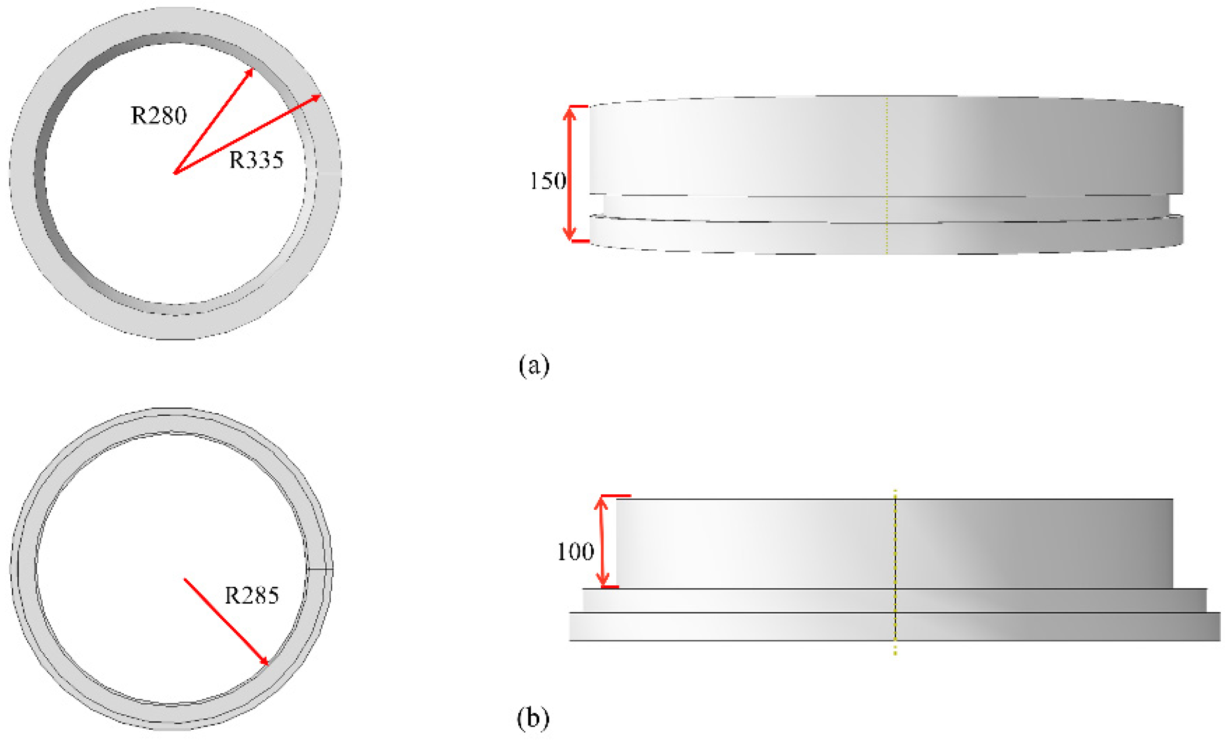
The initial blank model is shown in
Figure 4a, while
Figure 4b shows the design part model. The widely used 2A70 aluminum alloy is used as the part material, and its material properties are given in
Table 1.
5.1. Validation by Simulation
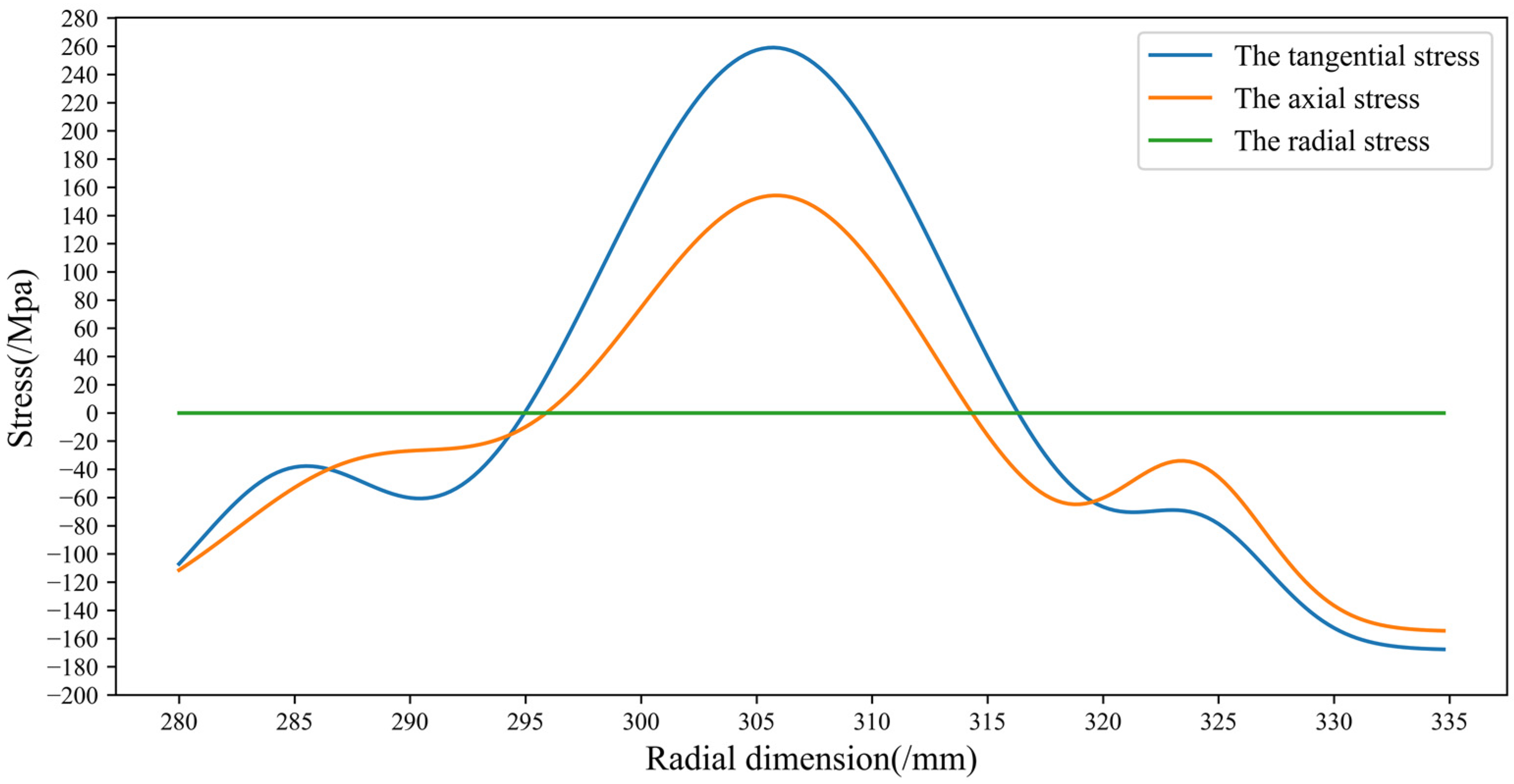
The actual machining process is simulated by a finite element simulator to obtain a large amount of part deformation force data for the ensuing neural network training and testing. The simulation was carried out in commercial finite element software ABAQUS. The thin-walled design part has a deformation-prone 3D geometry as shown in
Figure 4b. The residual stress data are shown in
Figure 5. The lower surface edge of the part is restrained to simulate the positioning and clamping in the finite element environment. The deformation force at any clamping point is obtained by applying the fixed constraints, and the calculated node force of the deformation monitoring point is equivalent to the deformation force.
The deformation force dataset generated from the simulation is then fed to the training model. Gaussian noise with a variance of 50 N is applied during the training process. If , it is considered that the direction of deformation within the machining step is the same as that of the support element arrangement under the confidence level . In this case, a smaller clamping force can be used according to our past experience. However, if, it is considered that the deformation direction in the machining step is opposite to the support element arrangement at the confidence level .
The deformation force verification data are generated the same way as the training data. For the verification data set, if
, the clamping force can be monitored. The prediction probability model of deformation force is compared with the traditional approach of using the mean value of deformation force in the training set as the basis of applying the pre-support force. The monitoring success rate of clamping force in each machining step is shown in
Figure 6. If the support force is applied according to the average value of the deformation force, the clamping force monitoring is effective at around 50%. If pre-support is applied only according to the end-to-end model (
), the results may be too poor at certain machining steps. The simulation results show that the application of pre-support forces according to a probabilistic model can effectively improve the success rate of clamping force monitoring.
Next, the machining process is simulated with a finite element solver to verify the effectiveness of the proposed method. The new residual stress data are generated by adding noise to the simulated residual stress data. When using the finite element solver, the effect of auxiliary support is simulated by exerting a displacement. Different from actual machining, the applied displacement is calculated based on the deformation force distribution, the confidence degree (
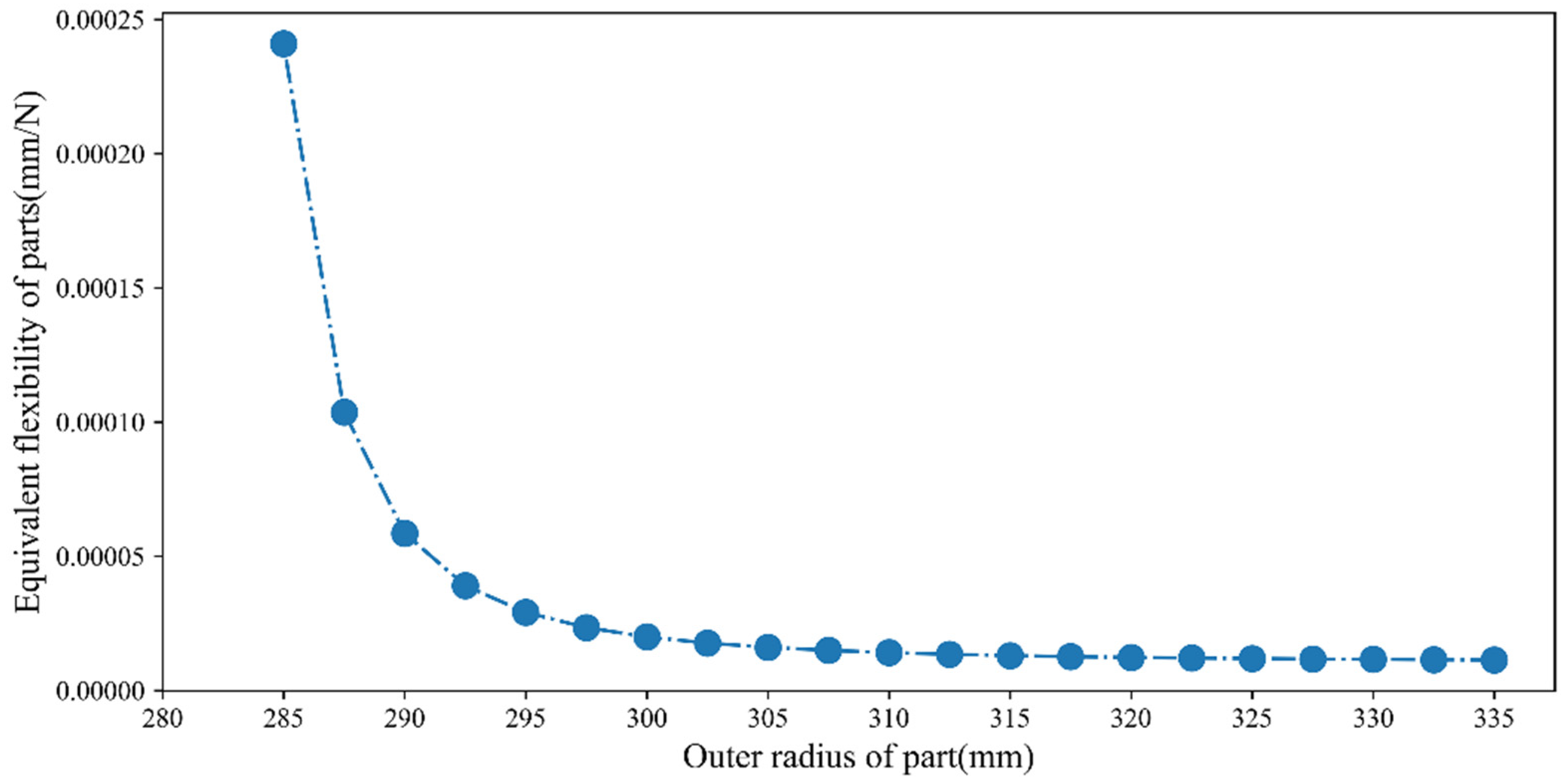
), and the equivalent flexibility. As previously stated, the node force of the deformation monitoring point is equivalent to the clamping force. In addition, the real deformation force is obtained by exerting the fixed constraints. The equivalent flexibility is obtained by simulation too, as shown in
Figure 7. The variance of the measured values is set empirically, i.e., 5 in this work.
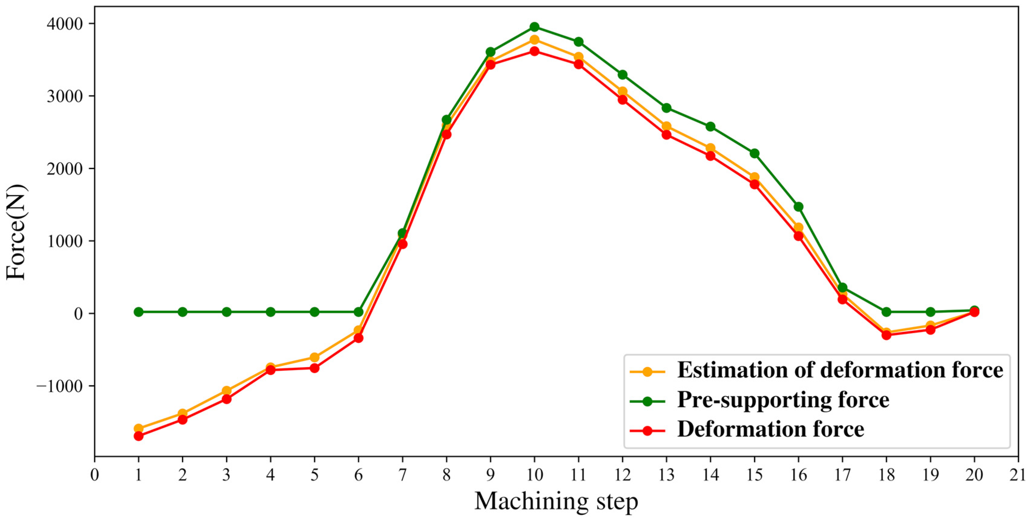
Figure 8 shows the discrepancy between the exerted pre-support forces and the calculated deformation forces, which confirms that the proposed model learns the distribution of deformation force data well, including the deformation direction. The error in the estimation of the deformation force is 10.93%, which suggests that the pre-support force calculated based on the estimation of deformation force can be used with sufficient confidence. Basically, when the in-process workpiece deforms inward, we exert a small support force (20 N) based on the past experiences; on the other hand, when the in-process workpiece deforms outward, we will exert a support force based on the distribution of deformation force, the confidence degree (
), and the equivalent flexibility.
Figure 9 shows the simulation results at some machining steps, where deformation directions are marked.
When simulating the process of releasing the deformation of a part, we retain the constraints at the force exertion and clamping points, remove the constraints at the auxiliary supports, and calculate the deformation at each machining step based on the displacements at the support points.
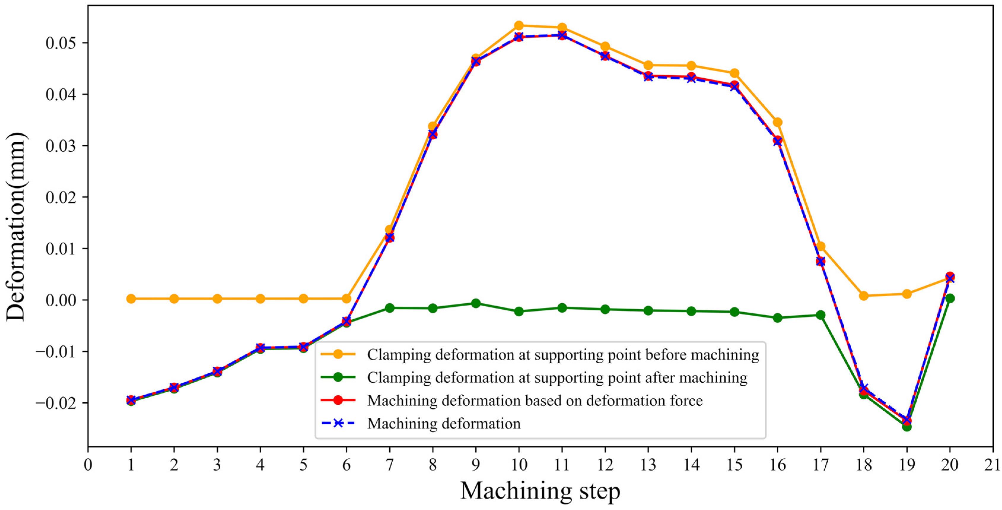
Figure 10 shows the variation of clamping deformation before and after the machining with the supporting forces and the discrepancy between the real (i.e., measured) and the estimated machining deformations. The clamping deformation before machining is less than 0.06 mm and the final effect of clamping deformation is less than 0.003 mm. In principle, an exerted pre-deformation force could compensate the part deformation, i.e., pre-deformation force can help reduce the final part deformation.
5.2. Validation by Physical Machining Experiment
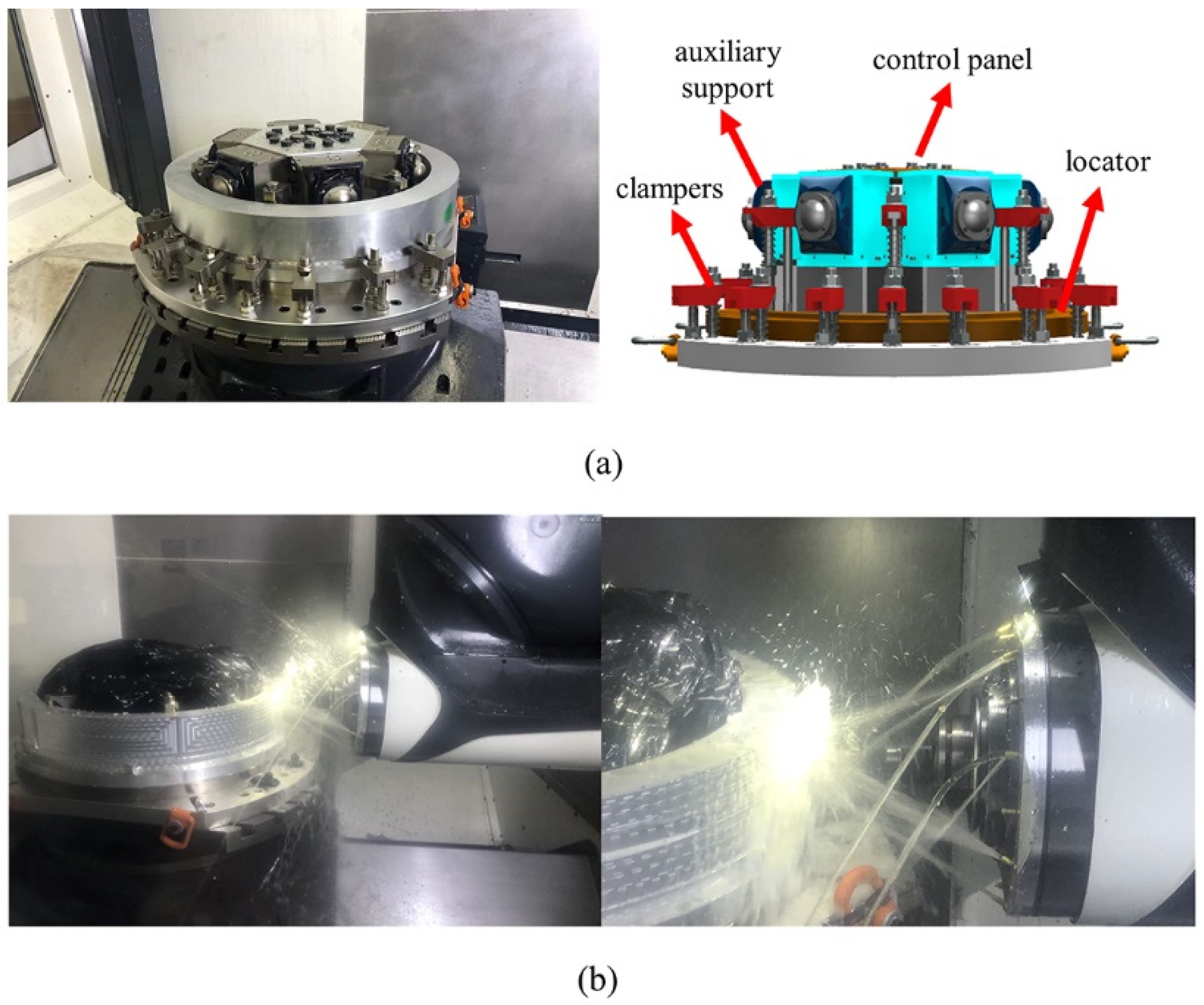
The proposed method is also verified by physically machining an aluminum alloy aero-engine casing part on a DMG 80P machine tool. In the experiment, the machining parameters are set as follows: spindle speed 6000 rpm, cutting depth 1.25 mm, cutting width 8 mm, feed rate 1000 mm/min, and tool diameter 20 mm. In order to monitor the radial deformation force of the part, a fixture with both clamping force control and monitoring function is designed and fabricated as shown in
Figure 11a. The fixture consists of a flat positioning element, a plurality of axial clamping element, and the auxiliary supports arranged along the circumference.
The part is machined while the change in clamping force being monitored and recorded, as shown in
Figure 11b. The pre-support force is exerted according to the proposed model, and the deformation forces are monitored/recorded at certain machining steps of the in-process workpiece, based on which the corresponding part deformation is calculated.
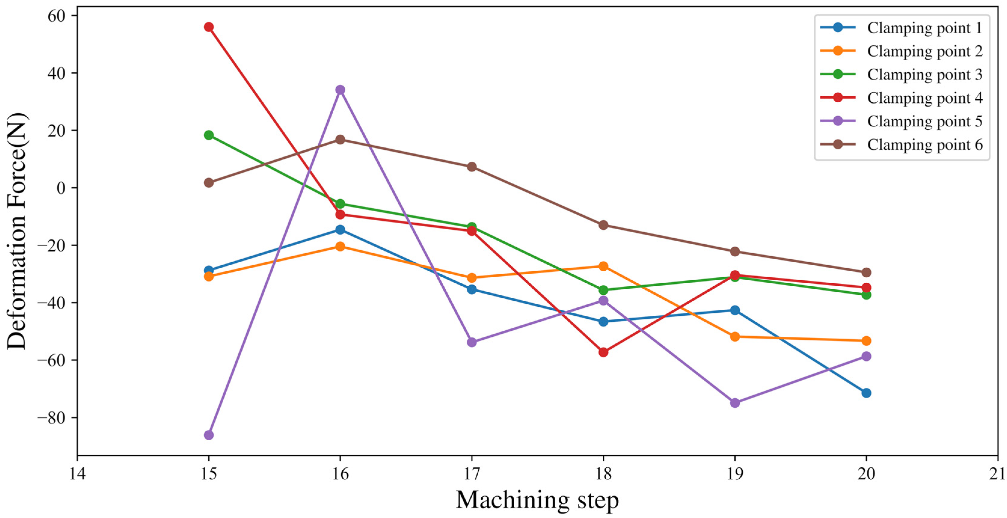
Figure 12 shows the deformation forces monitored in the experiment. It is necessary to mention that, if the thickness of the part is too large, it will be inaccurate to calculate the deformation of the measurement points which will be outside the part based on the calculated deformation forces at the clamping points. The amounts (in mm) of deformation respectively obtained by our estimation model and physical measurement are both listed in
Table 2, which show an error range of 0.001–0.008 mm.
6. Discussion
From the experimental results of both computer simulation and physical machining of our proposed method, the following notes can be made.
(1) Due to the unique structure of an aero-engine casing, i.e., it is axisymmetric, the fixture elements are arranged in an axisymmetric manner, and the interactions among fixtures are simple. If complex fixtures are used, mutual coupling between the fixtures should be considered.
(2) The proposed method may cause a certain amount of clamping distortion to the part before machining. In order to prevent the support force from affecting the subsequent machining, the maximum support force should be calculated based on the machining allowance and the equivalent flexibility. However, not all of these clamping deformations are harmful. Part of the clamping deformation will be eventually offset by the part machining deformation, which is actually beneficial to improving the machining accuracy of the part. Harmful clamping deformations are mostly due to prediction errors. The confidence level selected can be adjusted according to the machining accuracy during the actual machining process.
(3) The model training data in this work are obtained from simulation. Naturally, there is always a gap between a simulation environment and the real physical machining environment due to errors in the estimation of various physical data, such as the cutting force, cutting heat, residual stress, and intrinsic model errors. The gap is reduced in our model by using the Kalman filter via fusing the predicted and measured data. In our future work, more practical data will be accumulated, which will improve the accuracy of the model predictions and the contrast of the predicted distribution.
(4) The proposed method requires a special fixture to accurately exert the support force. Nevertheless, the current fixture used in the experiments is not sophisticated enough to accurately control the support force; thus, further improvements on the design of the fixture are needed.
(5) The accuracy of measurement of the deformation force is limited to a large extent by that of the clamping force measuring device. The device will be further improved to reduce the effects of machining vibration, cutting force and cutting fluid, so to enhance the measurement accuracy of the clamping force.
(6) The existing deformation monitoring methods are usually only applicable to locators or clampers but not auxiliary supports. However, for thin-walled aerospace parts, it is very difficult to perform finish-machining using only positioning and clamping elements without any auxiliary support. In other words, they are insufficient in actual parts processing. The proposed deformation force monitoring method based on adaptive adjustment provides a good example for monitoring the deformation force due to auxiliary bracing. It can also be extended to other types of auxiliary support.
(7) Most existing methods based on applying clamping forces and monitoring the deformation force are not stable, due to the lack of residual stress data and deformation force training data. We are currently conducting another study on how to estimate the residual stress distribution of an areo-engine casing blank based on the deformation force. Once the initial residual stress distribution in the blank is obtained and incorporated into the proposed method, the accuracy and effectiveness of the proposed method are expected to be substantially improved.
(8) In the experiments of this study, the pre-support force was adjusted at each step. However, for practical use, as long as the pre-support force meets the monitoring requirements and the clamping deformation meets the manufacturing requirements, the number of adjustments of the fixture could be reduced.
7. Conclusions
We have presented a new method for better monitoring and controlling the part deformation when an aero-engine casing is being machined. By integrating force sensors into the fixture, the deformation force on the part can be monitored. However, as the auxiliary supports of aero-engine casing fixture acting on the sidewalls can only provide a one-way support force, the part and fixture may be separated from each other during machining, making the monitoring of the deformation force impossible. As a solution, we have proposed a deformation force monitoring method based on applying a pre-support force. However, due to the introduction of pre-support force, the following three major concerns are introduced:
- (1)
Besides the deformation force, the clamping force is also affected by the stiffness of the part.
- (2)
The deformation cannot be determined in advance, which leads to a low success rate in monitoring the deformation force.
- (3)
The pre-support force must not be too large, as it would cause a large clamping deformation and hence affect the machining accuracy.
We solve the above three problems through the following work. First, a set of sophisticated clamping devices with force sensors are developed. Second, we establish the conditions of auxiliary support failure and a method for calculating the deformation force based on the concept of equivalent flexibility. Third, we propose a probabilistic model to predict the deformation force of the future subsequent machining step by the use of deep autoregressive network and Kalman filtering. The probabilistic model predicts the subsequent deformation force based on the preceding deformation force, which can lower the risk of auxiliary support failure, while the Kalman filtering helps reduce the modeling and measurement errors. Ultimately, the support force is determined by the probabilistic model of deformation force prediction and the equivalent flexibility, whose use prevents the auxiliary support from failing (i.e., to guarantee the required deformation force).
Both computer simulation and physical machining verification are carried out, and the experimental results confirm the following. (1) The proposed deformation force prediction probability model can reduce the risk of auxiliary support failure—when the confidence is 84.1%, the success rate of deformation force monitoring is increased by about 30% compared with the traditional approach. (2) The proposed pre-support force decision method can effectively control the clamping deformation—the final impact of clamping deformation of the proposed method is less than 0.003 mm. (3) The proposed methodology for calculating and monitoring the deformation force is highly accurate—the calculation error of deformation by the proposed method based on using the predicted deformation force is less than 0.008 mm.
Our ongoing and further work is to incorporate the mechanics of elasticity into the predictive model to reduce the amount of training data required for the model and its accuracy. Furthermore, the problem of how to exert the support force to better control the deformation will also be investigated.


