1. Introduction
With the development of computer technology, machine vision, and micro/nano manufacturing, the study of intelligent vehicles is developing towards miniaturization and modularization and has come into application in various fields [
1,
2]. Intelligent vehicles can carry various sensors to detect the external environment, and they are able to perform logistics services, detection, and other functions. For instance, an AGV vehicle (
Figure 1) can be utilized to sort logistics.
A modular reconfigurable vehicle system refers to a group of modular units with the same or different configurations assembled according to a series of unit groups, and it can change its original configuration through the reorganization and transformation of different units and actively adapt to different environments. The modular vehicle can be decomposed into general units for optimization and fabrication, which greatly reduces the difficulty of design, debugging, and maintenance.
In 2002, the Japan Institute of Industrial Science and Technology designed a modular robot, M-TRAN Ⅲ [
3], as shown in
Figure 2. Each subunit is composed of two U-shaped structures that can rotate around the rotating shaft. Each unit can rotate ±90° under the action of the driving motor. Electromagnet coils are installed on each connecting surface to realize configuration reorganization and separation through the electromagnetic force generated between the two units.
The Lausanne Federal Polytechnic University developed a self-reconfigurable modular robot, S-bot [
4], as shown in
Figure 3. The S-bot has an active gripper and a passive gripper for the interconnection between different units. Each unit is equipped with a differential track drive, intelligent sensing, and independent decision-making controller, which guarantees its movement in a complex environment.
In 2010, the Beijing University of Aeronautics and Astronautics designed the Sambot modular robot [
5], as shown in
Figure 4. Each of its submodules integrates functions, such as driving, communication, power supply, and sensing, which guarantees independent decision making and mobility. Each Sambot unit has four active docking surfaces, which can independently reform the car configuration or bionic spider configuration, providing a multifunctional integrated platform. Experiments show that Sambot has the highest degree of freedom among the current self-reconfigurable robots.
The self-reconfigurable crawler designed by the Shenyang Institute of Automation, Chinese Academy of Sciences [
6], is shown in
Figure 5. The original design intention is that when exploring in an unknown environment on the surface of extraterrestrial planets, the self-reconfigurable crawler can form into a large platform through reconfiguration. Each unit is capable of moving, docking, and communication. Through the cooperation of multiple independent units, the robustness of location environment detection can be greatly improved [
7].
Swarmanoids are modular self-reconfigurable robots developed by Nithin Mathews at the Free University of Brussels, Belgium, in 2017 [
8]. Each modular robot has an independent CPU and sensor and can be split and merged into new formations, so its shape and size can be adjusted according to the task or environment. The modular robots communicate with each other using Wi-Fi.
Previous research works have shown the possible shape design of a reconfigurable vehicle and the expectations for the peripheral functions. However, previous studies have mainly focused on the development of control algorithms and the data fusion of sensors, which makes application in real scenarios difficult.
This paper designs and manufactures a novel self-reconfigurable modular intelligent vehicle system that can be potentially applied in orientation guidance, logistics handling, patrol inspection, and exploration in unknown scenes. The system consists of a central control vehicle and multiple physically independent submodule vehicles. When facing a relatively simple preset scene, each subcar can move to the designated position according to the preset motion algorithm under the control command of the central car. When faced with a more complex unknown scene, the central handlebar simplifies the scene into an existing preset scene so as to integrate the formation control strategy into various scenes. Each vehicle is equipped with Mecanum wheels to obtain the highest degree of freedom of movement in the plane.
In general, the main features of the proposed modular intelligent vehicle system are as follows: (i) each modular vehicle has independent motion capability in three degrees of freedom (DOFs), and the mobility of each modular vehicle will directly affect the flexibility of the whole system; (ii) the modular vehicle should have multiple junction faces and a reliable connection mechanism so as to realize a variety of configuration postures; (iii) each modular vehicle has data processing and communication capability; and (iv) each vehicle is powered independently.
2. Mechanical Design and Fabrication
The Mecanum wheel is utilized as the driving mechanism for its unique motion flexibility, which makes it an ideal choice for movement in a narrow space [
9]. In the reconfigurable vehicle system proposed in this paper, four Mecanum wheels are driven by four independent driving motors so that each Mecanum wheel has an independent speed and steering control mechanism. The control chip on the submodule vehicle first receives the target position signal sent by the main control vehicle, and then calculates the motion direction and speed of each Mecanum wheel according to kinematic equations. Finally, the motion data are converted into the actual motor drive signals [
10,
11].
The Mecanum wheel is an omnidirectional wheel structure; it is mainly composed of a wheel hub and a circle of rollers whose axis is arranged at 45°. When the Mecanum wheel rotates, the envelope of each roller is approximately circular. Through the speed vector synthesis between the four Mecanum wheels, as shown in
Figure 6, motion in both the longitudinal and lateral directions can be realized. The arrangement of the four Mecanum wheels is shown in
Figure 7. The axis of the rollers is end to end, and the contact points of the four wheels are in rectangular shape. In this arrangement pattern, the torque generated by the rollers has a long effective force arm, which guarantees the stability of the spin and trim. It is thus the most common pattern of Mecanum wheel arrangement.
A magnetic suction structure is mounted on each longitudinal and lateral face of the modular vehicle (
Figure 8), which guarantees a stable connection between each modular vehicle. When the modular vehicle departs from each other, the driving force in both longitudinal and lateral directions will overcome the magnetic force so as to realize reformation.
A camera is mounted on a frame in the central vehicle, and the fixation angle of the camera can be adjusted to make sure each modular vehicle is within the scope of the camera. After the image capture, the location and posture of each unit are calculated, and motion commands are made correspondingly.
3. Kinematic Analysis
In the kinematic model analysis, the motion of the modular vehicle in the horizontal plane can be divided into three independent DOFs: X-axis translation, Y-axis translation, and rotation around the Z-axis (yaw angle). Based on the inverse kinematics model, the corresponding relationship between the four Mecanum wheels and the motion state of the modular car is established, and the forward kinematics model should also satisfy this relationship [
12].
First, the coordinate system is established at the geometric center of the modular vehicle. The forward movement direction of the modular car is the positive direction of the X-axis, the left translation direction of the modular car is the positive direction of the Y-axis, and the vertical modular car is the positive direction of the Z-axis, as illustrated in
Figure 9. Assume that the linear velocity of the modular vehicle is
v;
Vx and
Vy are components of
v in the X- and Y-axis, the rotational angular velocity of the modular vehicle is
w;
Vrn (
n = 0,1,2,3) is the rotational angular velocity;
Vwn (
n = 0,1,2,3) is the vector sum of
v and
Vrn in the world coordinate, which represents the velocity vector of each Mecanum wheel; a and b are 1/2 of the distance between Mecanum wheels in longitudinal and lateral directions.
Assume that (i) the Mecanum wheel is closely attached to the ground and there is no idle, and (ii) the geometry center is identical to the gravity center [
13].
The resultant speed of each Mecanum wheel
Vwn is:
Therefore, the resultant speed on each wheel is:
Assume that the unit vector alongside the roller is:
Each
un is related to the orientation of the roller. The corresponding
un of each Mecanum wheel is:
The velocity component of the four Mecanum wheels parallel to the roller direction is:
The relationship of each wheel between the velocity component and the rotation speed
wn is:
The speed of each Mecanum wheel is:
where
r is the radius of the wheel.
The inverse kinematic equation of a modular vehicle is:
Solving Equation (8), the forward kinematic equation of a modular vehicle is:
Therefore, the corresponding relationship between the motion of the modular car in the plane and the speed of the four Mecanum wheels is unique. The omnidirectional motion on the plane is realized by controlling the speed of the four Mecanum wheels, and the speed of the modular vehicle is the synthesis of the four wheels’ speed vectors [
14].
4. Visual Positioning Algorithm
With regard to identifying graphic codes, we make a comparison between various graphic codes, including the HoloBar code, which is robust to image occlusion [
15], and AprilTag is finally selected mainly because of its simplicity, allowing a fast calculation in the main control vehicle. In the self-reconfiguration motion control of modular vehicles, AprilTag [
16,
17] is first identified via a monocular camera so as to evaluate the spatial location and attitude of the vehicle [
18]. Afterwards, the position and attitude are adjusted accordingly to ensure its movement in a preset route. According to the requirement of positioning accuracy, the size of AprilTag is designed as 4 × 4 cm, and AprilTag is attached to the vehicle. The center of AprilTag is identical to the center of the modular vehicle (
Figure 10).
The image captured by the monocular camera goes through processes, such as image enhancement, image binarization, image filtering [
19], AprilTag extraction and decoding, and position calculation, and is finally utilized to evaluate the position and attitude (
Figure 11).
After the identification and decoding of AprilTag in the image, the spatial position and attitude of the modular vehicle can be estimated. The geometric center of the AprilTag of each vehicle coincides with the geometric center of the modular vehicle with the same positive direction. An OpenMv camera is installed on the main control vehicle, and the AprilTag on three submodule vehicles is photographed from a certain angle. The spatial position of each modular unit relative to the main unit can be obtained by detecting each AprilTag (
Figure 12).
The pitch angle of OpenMv is adjusted to ensure that each modular unit has a sufficient range of movement, and AprilTag can be accurately identified.
Equation (10) gives a method for estimating the field of view range.
θ is the angle of view,
w and
h are the width and height of the view, and
f is the camera focal length.
After calculation and debugging, the intersection angle between the OpenMv camera and the horizontal line is 43°, and the motion range is a 45 × 65 cm rectangle plane in front of the main modular vehicle (
Figure 13).
A coordination system is established for the picture taken by OpenMv, with O
C as the center point of the picture, the forward direction of the modular vehicle as the Y-axis, and the right translation direction of the main control car as the X-axis, as shown in
Figure 14. Through the identification and positioning of AprilTag, the coordination and attitude of the modular vehicle in the OpenMv coordinate system can be obtained. The position and attitude information of the modular vehicle is packaged and output through the serial port, as shown in
Figure 14, where T
X, T
Y, and T
Z represent the coordinate of the modular car in the OpenMv coordinate system, R
X represents the rotation angle of the modular car around its own X-axis, R
Y represents the rotation angle of the modular car around its own Y-axis, and R
Z represents the current yaw angle of the modular vehicle.
When the number of submodule vehicles that can be detected in the main module car’s view is inconsistent with the preset number, for example, the submodule vehicle goes beyond the field of the camera view or AprilTag cannot be recognized, the main module vehicle will track and rotate within a certain range until a sufficient number of submodule vehicles are captured. The captured vehicles will be gathered in the same visible field according to the instructions of the central control vehicle. The reconfiguration procedure is shown in
Figure 15.
5. Experimental Validation
5.1. Hardware and Communication Setup
The hardware architecture for reconfigurable modular vehicles is shown in
Figure 16. The OpenMv monocular camera on the main control vehicle detects the position and attitude according to AprilTag on the submodular vehicle and sends the 6-DOF information of the three modular vehicles to the MCU. Then ESP8266 converts the acquired position information into the speed information required by the four vehicles, and sends it to ESP8266 on each submodular vehicle through the on-chip Wi-Fi module. After receiving the speed information, the ESP8266 module on the submodule vehicle sends it to the ATmega328p single-chip microcomputer through the serial port, and makes the closed-loop control according to the motor speed feedback signal to realize the motion control of each submodular vehicle. Theoretically, through this framework, more submodular vehicles can be added into the system to contribute a more complex self-reconfigurable system.
The DRV8701E motor drive chip of the TI company is used as the motor drive scheme of the modular car, as shown in
Figure 17. DRV8701E utilizes an H-bridge to drive a 12–24 V bidirectional brush motor. The DRV8701E chip is also equipped with an operational amplifier to realize current sampling and overcurrent protection. A schematic diagram and a PCB board of the motor drive circuit are shown in
Figure 17.
A GA12-N20 DC motor with an encoder is selected as the driving motor, its driving voltage is 12 V, the speed is 200 rmp, and the rated power is 3.6 W. Detailed parameters can be found in
Table 1. The connection mechanism of a motor with a Mecanum wheel is shown in
Figure 18.
Three lithium battery packs connected in series are utilized as the power source, as shown in
Figure 19. The voltage of each battery pack is 3.7
–4.2 V, the maximum outage current is 3A, and the capacity of each pack is 2300 mAh. A protection board is utilized to balance the charge/discharge current of the three battery packs.
5.2. Reconfiguration
When the modular vehicle is within the visual range of the monocular camera, the coordinate of each AprilTag’s geometric center and its rotation relative to the three axes can be calculated through the identification and positioning algorithm; then the results are sent to the ESP8266 module of the main control vehicle through the serial port (
Figure 20).
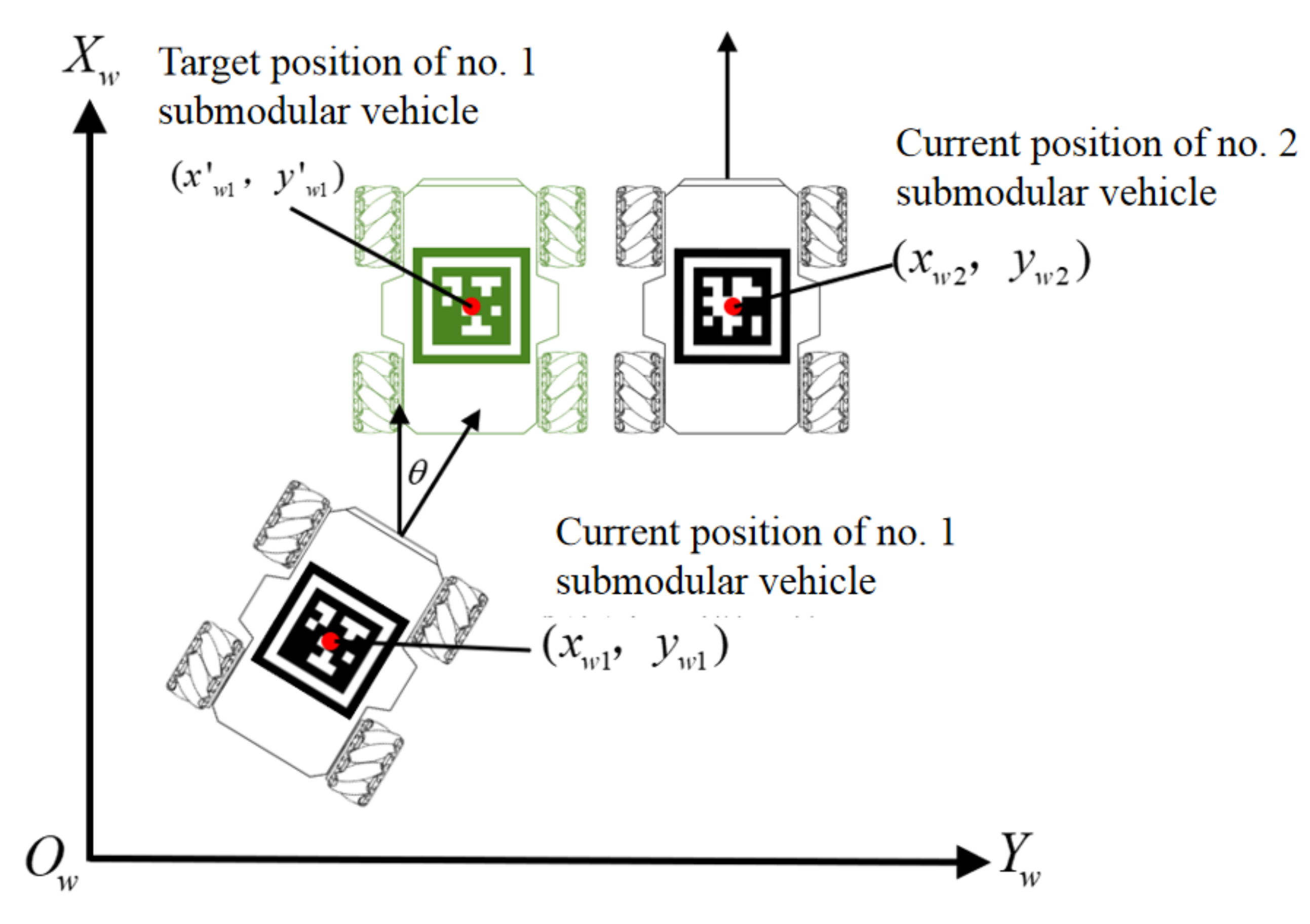
In the modular vehicle group, the ESP8266 module of the main vehicle reads the spatial attitude and position information transmitted by the OpenMv module and calculates the coordinate information of the submodular vehicle in the world coordinate system, as shown in
Figure 21. After making a difference between the coordinates of the target modular unit and the coordinates of the current modular unit, the result is sent to each submodular vehicle through an ESP8226 network.
The difference in coordination received by each submodule vehicle represents the movement direction of the modular car (positive value means to move forward in this direction; negative value means to move backward). The offset in the X-axis is compensated through the front and rear linear movement, the offset in the Y-axis is compensated through the left and right linear movement, and the yaw angle offset around the Z-axis is compensated through the spin.
Two submodule cars can also communicate with each other through each ESP8266 module. When the two submodule cars detect that they are in close contact with each other, they will enable the connection magnetic attraction device in the corresponding direction according to the position information to realize the fixed configuration. When the two submodule cars detect that they are about to be separated, the magnetic attraction device in the corresponding orientation will be closed to complete the configuration decomposition.
After completing the configuration reorganization, each submodule car still receives the motion command of the main module car. At the same time, each submodule car will use the mutual communication between ESP8226s to complete an additional motion coordination program to ensure the consistency of the car group when moving in a fixed configuration. Magnetic attachments around each car will ensure the physical connection of the overall movement.
In order to measure the positioning accuracy of the submodule car by the reconfiguration control, the modular car is arranged in a grid plane of 40 cm × 40 cm, and the OpenMv field of view is aligned with the center of the grid plane. The measured values averaged five times are compared with the coordinates set in the simulation, and the error between the simulated coordinates and the measured world coordinates is shown in
Figure 22. According to the experimental results, the positioning error of the submodule car is less than ±4 mm, and the positioning error of the yaw angle is within ±1°, which can meet the needs of reconfiguration control.
5.2.1. “—” Shape Reconfiguration
In the “—” shape reconfiguration, three modular vehicles are lined up in one straight line. At this time, the main control vehicle and three submodular vehicles receive unified speed instructions and maintain a relatively static state with each other.
The main control vehicle looks for the vehicle with no. 2 AprilTag through the OpenMv camera, sets its coordinate information in the camera coordination system as reference, and calculates the target position information of no. 1 and no. 3 vehicles according to the “—” shaped configuration. Then the coordinates of the target path are sent to the corresponding vehicle according to the preset reconstructed motion trajectory. When the modular vehicle traverses each received coordinate, it will finally reach the target position. The specific process is as follows (
Figure 23): The no. 1 modular vehicle corrects its yaw by rotating in place; then it goes straight ahead to the target coordinate, and then translates to the left of the no. 2 modular vehicle. The magnets on both sides of the modular vehicles help to connect the no. 1 and no. 2 vehicles. The movement procedure of the no. 3 modular vehicle is similar to that of the no. 1 modular vehicle and is thus omitted here.
5.2.2. “|” Shape Re-Configuration
The transition from the “—” to “|” shape configuration is shown in
Figure 24. The detailed process is as follows: The no. 1 modular vehicle moves to the left to separate from the magnetic connection with the no. 2 modular vehicle. After driving straight ahead to the target coordination, it then moves to the right. Finally, it reaches the target position and finishes the configuration through the magnetic connection with the no. 2 vehicle. The movement procedure of the no. 3 modular vehicle is similar to that of no. 1 modular vehicle, and is thus omitted here.
Compared with the distributed state to form the “—” shape, the reconfiguration from the “—” shape to the “ | ” shape is simpler, because the main car does not need to refind enough submodule cars in the field of view, and the location information of each submodule car is known. At this point, the reconfiguration can be completed by simply moving the specific numbered car to the target position according to the preset reconfiguration procedure.
5.3. Results and Discussion
Table 2 gives the experimental results of the reconfiguration of the proposed intelligent modular vehicle group with one central control vehicle and three submodular vehicles.
In
Table 2, reconfiguration success is defined as: when each submodule car correctly enables the magnetic connection mechanism in the corresponding orientation, the car itself will not have a large deviation. Average time is calculated as the average time for all successful reconfiguration experiments. All experiments start from the disorderly dispersed state of the submodule vehicles and end with the completion of the overall configuration.
The “ | ” shape configuration is relatively easy, the success rate is high, and the average time is short. The “ — ” shape configuration takes a longer time because of the lateral translation of the Mecanum wheel. The “ L ” shape configuration is more complicated, and the fusion of the “ | ” shape configuration and the “ - ” shape configuration needs to be considered in the reconfiguration process.
Table 3 gives the experimental results of the operation time of the proposed intelligent modular vehicle group with one central control vehicle and three submodular vehicles. Only communication means the whole vehicle group is working in a preset route but not reconfiguration. Keep reconfiguration means the whole group keeps reconfiguring from one shape to another. Heavy load means a 3 kg weight, which is almost five times the weight of the car, is attached to each submodular vehicle.
Modular robots are generally limited in working time due to volume constraints. The modular vehicle design in this paper intends to maximize the power density of each submodule. It is proved by experiments that the vehicle system has longer working endurance.
The system proposed in this paper includes a homogeneous submodule car and a heterogeneous host car with submodule cars. This ensures that the main vehicle can complete precise control, while the subvehicle can have sufficient redundancy when completing various tasks. From handling heavy objects to refined distribution, modular cars can be used in different scenarios and have good scalability.
A comparison between different modular cart systems is presented in
Table 4.
5.4. Application
When the modular car encounters cargo that is many times its own weight or volume, the reconstruction algorithm is used to change the overall configuration of the modular vehicle group. This increases the load capacity of the entire vehicle group. The stability of the configuration is ensured by the electromagnets between the modular vehicles, and the overall safety reliability and control stability are improved at the same time.
For example, when transporting long objects, a “|” type is formed, as shown in
Figure 25; the coordinated movement of multiple submodule cars is used to form a larger transport platform, which can transport objects with larger volume and weight, as shown in
Figure 26.
The reconfigurable modular vehicle can serve as both industrial robots and service robots. It can assist humans to complete repetitive tasks, such as handling, unloading, and distribution in production [
25]. With accurate visual positioning and omnidirectional movement capabilities, the self-reconfigurable modular vehicle can complete semiautonomous or fully autonomous tasks in different scenarios. In the future, AI technology can also be integrated on the vehicle platform to complete more intelligent decisions.
6. Conclusions
In this paper, a reconfigurable modular vehicle is designed and fabricated, together with its driving, communication, and power supply system. A magnetic connection mechanism ensures the whole stability of all submodular vehicles in the process of moving. After that, the modeling and kinematic analyses of the modular vehicle are carried out to verify its ability of omnidirectional movement in the plane. A visual positioning system based on AprilTag is proposed, the main control vehicle successfully discriminates the spacial position and attitude state of other modular vehicles, and the feasibility of solving the position and yaw angle of each modular car in the world coordinate system is tested. Finally, under the visual positioning control system, the reconfiguration experiment of the submodular vehicle is carried out, and the process of realizing the reconfiguration from the “—” shape to the “|” shape is presented. The experimental results prove that the hardware setup and control algorithm of the self-reconfigurable modular vehicles proposed in this paper are feasible and robust, and the reconfiguration process has high accuracy. Modular vehicles can form different configurations according to different application occasions, which greatly improves the environmental adaptability of the intelligent vehicle system.


 ,
, 


