Article

Influence of Cutter Head on Cavitation of Non-Jammed Submerged Grinder Pump

National Research Center of Pumps, Jiangsu University, Zhenjiang 212013, China
*
Author to whom correspondence should be addressed.
Appl. Sci. 2022, 12(12), 6112; https://doi.org/10.3390/app12126112
Submission received: 4 April 2022 / Revised: 9 June 2022 / Accepted: 10 June 2022 / Published: 16 June 2022

Abstract

:
For the investigation of the cavitation of non-jammed submersible grinder pumps, a GSP-22 model pump was numerically simulated based on CFX. ICEM-CFD was applied to a structured mesh for the flow components. Pump performance and the influence of the cutter head on cavitation with different cutter head numbers and shapes were investigated. The results were as follows: with increases in the number of cutter heads, the effects of the cutter heads on the water increased, and the flow rate near the cutter head increased correspondingly—which eventually led to aggravated cavitation near the cutter head of the non-jammed submersible grinder pump. The head of the submersible grinder pump with a streamlined cutter changed little compared to the pump with a non-streamlined cutter; the overall power declined by 13.2% and the highest efficiency increased by 6%. For all pumps with different numbers of cutter heads, the vapor volume fraction of the streamlined cutter head was lower than that of the non-streamlined cutter head, and the vapor distribution area size of the streamlined cutter head was smaller than that of the non-streamlined cutter head. This means that changing the cutter head shape to streamlined can effectively control the cavitation intensity near the cutter head.

1. Introduction

A non-jammed submersible grinder pump is equipped with a grinding device for grinding debris at the inlet of the vortex pump. It can effectively cut and grind the debris entering the inlet of the vortex pump, therefore ensuring that the vortex pump has better performance when conveying sewage. The non-jammed submersible grinding pump can grind domestic sewage containing gloves, cotton yarn, sanitary napkins and bones or other debris thoroughly. Thus, it is widely used in rural areas, hospitals, hotels, domestic wastewater and sewage discharge. The grinding device of a non-jammed submersible grinding pump is composed of a movable cutter head and a static cutter head. The sundries are ground through the cooperation of the cutter head on the movable cutter head and the semi-circular flow channel of the stationary cutter head, and finally, small particles are formed. The particles enter the impeller channel [1].
In recent years, a series of investigations on non-jammed pumps and grinding devices have been carried out. Shi [2] summarized the current research status and development trends of non-jammed pumps. Guan [3] proposed a practical design method for non-jammed pumps based on his design experience called the Drawing Method, designing the pump by drawing it in software after the determination of some important parameters. Wang [4] studied the hydraulic performance and pressure pulsation characteristics of grinder pumps under different clogging conditions; it was found that with increase in the number of static cutter heads, the clogging degree of the flow channel increases, the head changes into a parabolic shape and the maximum efficiency point is shifted to a low flow point. The passing frequency of the dynamic cutter is the most important factor that affects the pressure pulsation. When part of the static cutter runner is completely clogged, the interaction between the dynamic cutter and the stationary cutter is the most important factor affecting the pressure pulsation. Static cutter models with different degrees of clogging are shown in Figure 1. Fu Qiang [5] conducted research on the cavitation and pressure pulsation characteristics of a non-jammed submerged grinder pump. It was found that, as the level of runner blockage increased, the cavitation close to the cutters was intensified and became more serious; the cavitation at the back of impeller inlet also became more serious. Cavitation distribution inside grinder pump at different degrees of blockage is shown in Figure 2.
For the study of cavitation in pumps, various investigations have been carried out. Zhang Ning [6] studied cavitating flow-induced unsteady pressure pulsations in a low-specific speed centrifugal pump. It was found that the cavitation cloud in a typical stage is partially compressible, and the emitted pressure wave from a collapsing cavitation bubble is absorbed and attenuated significantly. The cavitation performance and cavitating flow structures of a centrifugal pump are shown in Figure 3.
Long Yun [7,8] proposed a novel and fast cavitation prediction method based on the impeller pressure isosurface in single-phase media. The feasibility of this method was demonstrated in combination with experiments, which greatly accelerated pump hydraulic optimization design in engineering, and the investigation evaluated the sensitivity and accuracy at different flow rates. Long Yun [9] conducted research on the hydrodynamics of high-velocity regions in a mixed-flow pump based on experimental and numerical calculations at different cavitation conditions. High-speed photography technology was used to capture the cavitation flow structures and reveal the physical process of cavitation evolution in a mixed-flow pump. By extracting 24 m/s water velocity isosurface and analyzing the water superficial velocity on the isosurface, the flow characteristics in the high-velocity fluid area under different cavitation stages were revealed, and the main factors affecting the development of the vortex structure in the high-velocity fluid area were summarized, as shown in Figure 4. Aimed at understanding the aggressiveness of cavitation structures and the intensity of impact as changed by microvortex generators, Ning Qiu [10] conducted an experimental investigation on impulsive loading on hydrofoil surfaces caused by collapsing cavities, and attempted to predict cavitation erosion aggressiveness and its relationship with cavitation structures based on visual observations. Qiu Ning and Long Yun [11] also conducted research on the assessment of cavitation erosion in a water-jet pump based on the erosive power method. Huang et al. [12,13] analyzed the cavitation and vortex structures in water-jet pumps; it is found that when cavitation occurs, the vortex expansion and baroclinic torque appear as violent fluctuations. Xu et al. [14] found that viscous dissipation has a larger magnitude at the tip clearance of water-jet pumps.
Cavitation of the pump can cause severe damage to material surfaces, reduce pump performance, and cause pump vibration and noise. This paper studies the performance of a GSP-22 non-jammed grinder pump with different numbers of cutter heads and cutter head shapes and studies the cavitation phenomenon of cutter heads.

2. Numerical Calculation Method

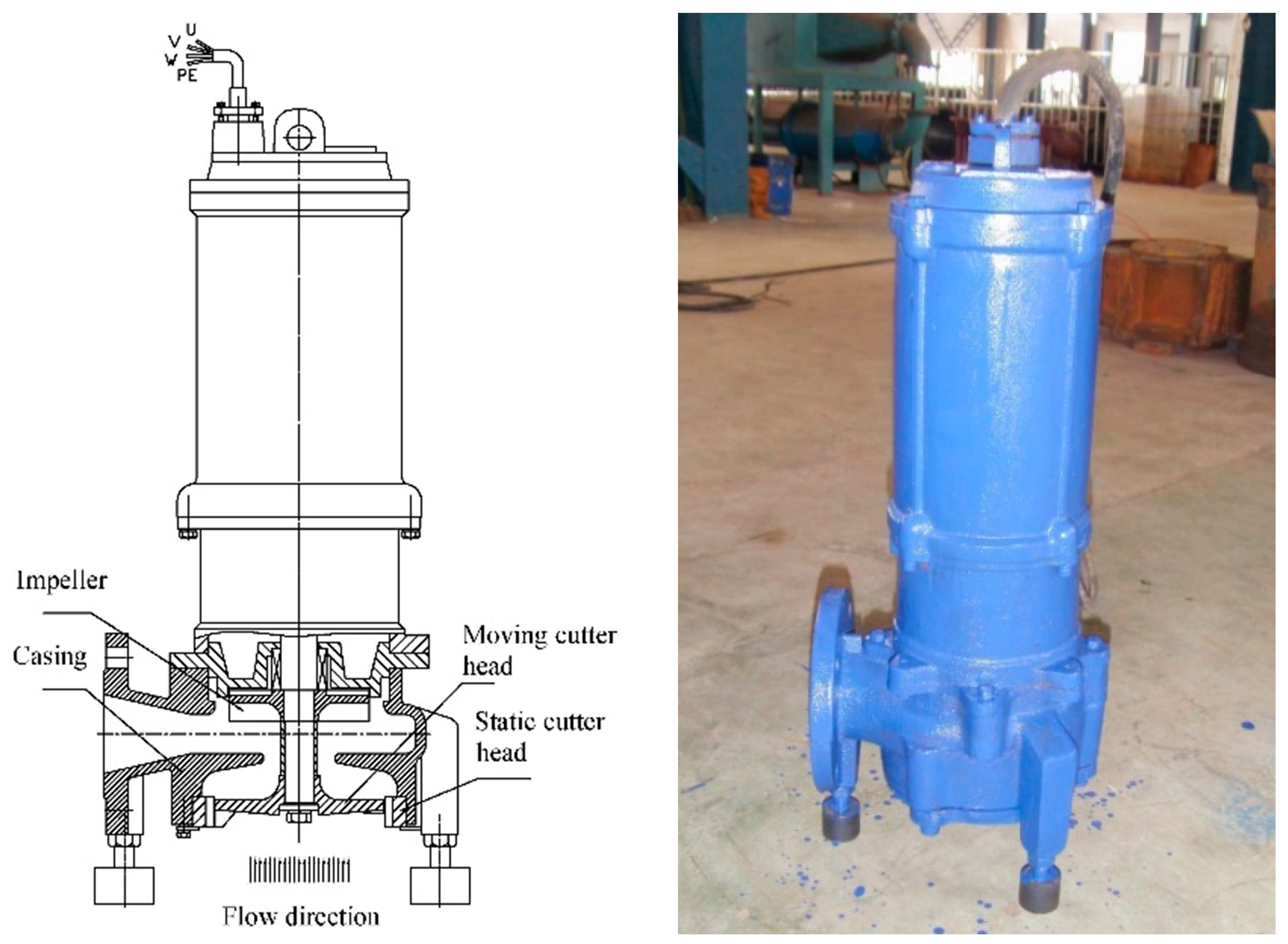
2.1. Structure and Working Mechanism of the Non-Jammed Submersible Grinder Pump

The non-jammed submersible grinding pump studied in this paper consisted of two parts: a grinding device and a pump. The pump part was composed of the impeller of the swirl pump and the pump body. The impeller retracted into the pump cavity behind the pressurized water chamber. When the impeller rotated, a runner flow and a circulating flow were formed in the non-blade cavitation in front of the impeller, and the runner flow passed through the flow between the impeller blades. The runner flow entered the pump chamber and flowed out, and the circulating flow circulated in the bladeless cavity. The grinding device consisted of a moving cutter head and a static cutter head. The sundries were ground through the cooperation of the cutter head on the movable cutter head and the semicircular flow channel of the stationary cutter head. The structure of the grinder pump is shown in Figure 5.
The working mechanism was to install the movable cutter head and the static cutterhead in front of the impeller inlet. The movable cutterhead and the shaft rotated together, and the static cutterhead was fixed onto the pump body. The stationary cutter disc was arranged with several semicircular flow channels on the circumferential surface for restricting the diameter of the passing particles, and two cutting edges were formed on both sides of the flow channel. When the debris entered, the passive cutter head would be thrown towards the circumferential direction of the grinding device. When the debris part entered the semicircular flow channel, it would be cut and ground by the high-speed rotating moving cutter disc and static cutter disc, and small particles or short fibers entered the impeller flow channel and were discharged through the pressurized water chamber.

2.2. Computational Model
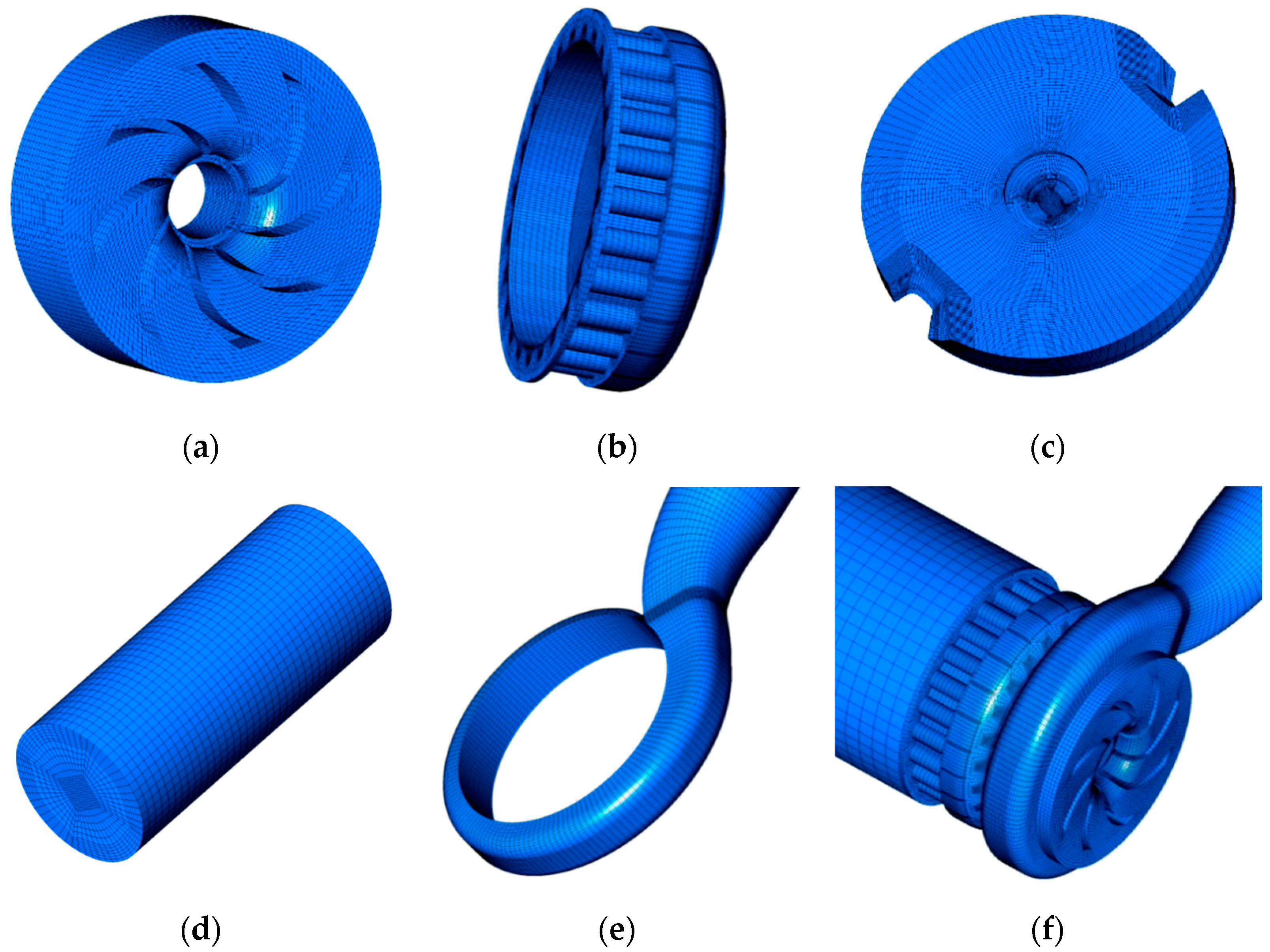
The calculation model adopted a GSP-22 non-jammed submersible grinder pump, which has 8 blades. The conveying medium was water, the flow rate was Q = 22 m3/h, the head was H = 10 m, the rotational speed was n = 2900 r/min and the specific speed was ns = 147.1. The outer diameter of the impeller was D2 = 110 mm, the outlet width of the impeller was b2 = 16 mm, the blade outlet angle was β2 = 80° and the width without the blade cavity was L = 26 mm. Figure 6 shows the computational model water body assembly and test cutter head.

2.3. Meshing

The model studied in this paper was meshed by ICEM-CFD. If an unstructured grid is used, the pseudo-diffusion of the calculation will be serious and the convergence will be difficult, due to the relatively long and narrow runner of the static cutter disk. Moreover, the pressure gradient at the cavitation site was large, the mesh needed to be locally refined, and a higher quality of mesh was required. The structural mesh can effectively control the quality and quantity of the mesh, which greatly reduces the level of calculation needed. Therefore, a hexahedral-structured mesh was chosen to mesh the model.
In order to determine whether the grid number and grid quality met the actual calculation requirements, the grid independence of the model was studied. As shown in Figure 7, when the number of grids was more than 700,000, the variation of the pump’s rated operating point lift was less than 5%. In order to ensure both the accuracy and economy of the calculation, this is appropriate when the number of grids is close to 1,000,000.
In order to reduce the pseudo-diffusion caused by the grid during the calculation process and to make the cavitation simulation more accurate, the single-phase flow simulation was firstly carried out, and the internal flow pattern was observed through post-processing—slightly fine-tuning for meshes whose trends do not match the direction of flow and recalculating the results until they were consistent in general. Therefore, at different operating points, there were always meshes that matched the flow conditions for each operating condition. The boundary layer Yplus of the hexahedral-structured meshes was always less than 100. Since cavitation is prone to occur near the cutter head, the meshes near the cutter head were refined, and the Yplus of the boundary layer of the cutter head was less than 30.
Figure 8 shows an example of the grid of each component of the water body of a non-jammed submersible grinder pump with two cutter heads. There are 236,872 grid cells in the water body of the moving cutter head, 319,456 grid cells in the static cutter head and rear runner, 189,544 grid cells in the impeller water body, 166,126 grid cells in the volute and 166,126 grid cells in the inlet water body. A total of 80,856 grid cells were in the inlet water body. The total number of grid cells was 992,854.

2.4. Calculation Method and Boundary Conditions

The CFD commercial software ANSYS CFX was used for the simulation. The equation system was discretized based on the finite element volume method. The convection term of the equation adopted the second-order upwind format and the diffusion term adopted the central difference format. This coupling technology has higher computation speed and stability. The standard k-ε turbulence model was used to consider the influence of turbulence. It was assumed that the initial velocity field and the initial pressure field were independent. The dynamic and static coupling surface between the impeller and the volute adopted the Frozen Rotor interface. The position of the rotor and stator was relatively fixed, and the upstream outlet data was directly transmitted downstream. The Reference Pressure was set to 0 atm, and the pressure in the flow field was the absolute pressure [8].
In order to make the calculated flow field closer to the real-life situation, the pressure inlet and velocity outlet were used to set the boundary conditions in the calculation. According to the submerged depth of the non-clogging submersible grinding pump in the actual workplace, the inlet pressure was set to 1.1 atm and the outlet flow to 22 m3/h. The wall roughness was set to 10 µm. The standard wall function was selected near the wall and the wall boundary condition was set to a non-slip wall. The vaporization pressure of the vapor was set to 3574 Pa and the vaporization pressure of the water at 25 °C. The average bubble diameter was set to 2 × 10⁻⁶ m. The volume fraction of the water at the pump inlet was set to 1, and the volume fraction of the bubble was set to 0. The convergence was based on the average residual RMS of all the control volumes in the computational domain and the convergence accuracy of RMS was set to 10−5.

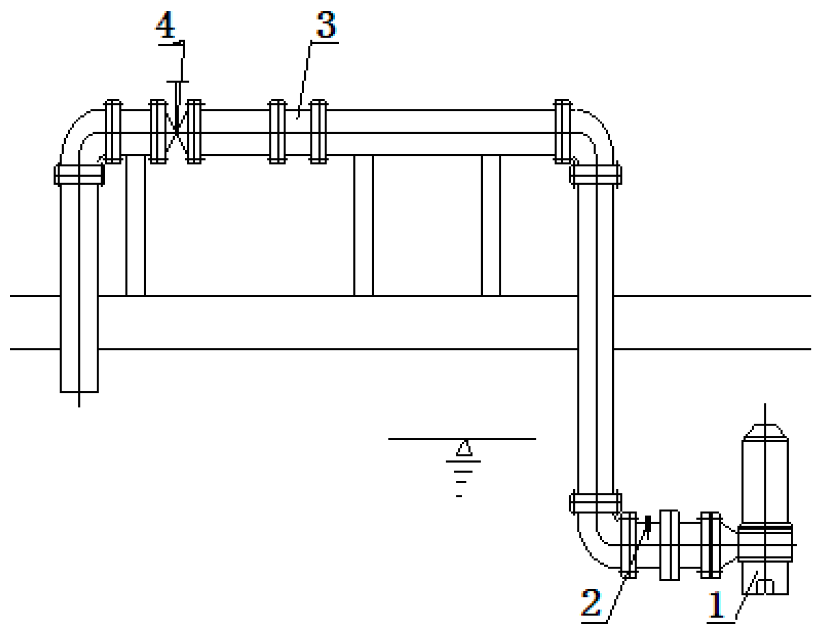
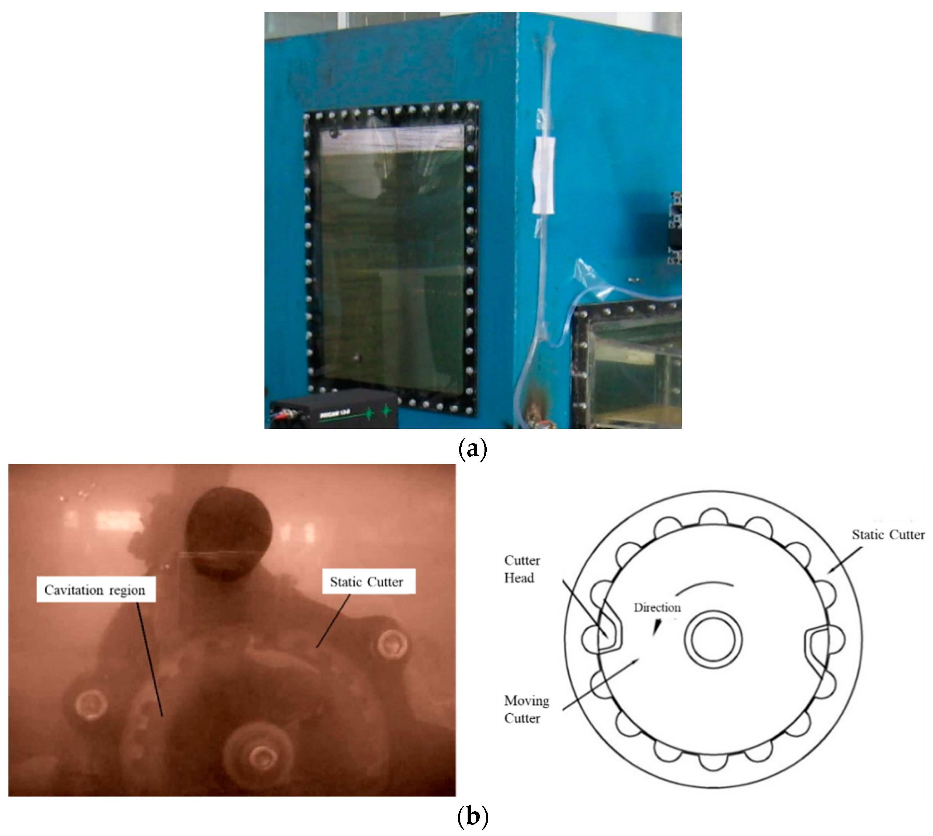
3. Experimental Setup

The performance test of the pump was carried out on an open test bench in a factory. The entire test system consisted of a non-jammed submersible grinder pump, a water outlet pipe, a test bench, a pressure gauge, a pressure sensor, a turbine flowmeter and a comprehensive pump parameter tester. The schematic diagram and prototype of the test device are shown in Figure 9.

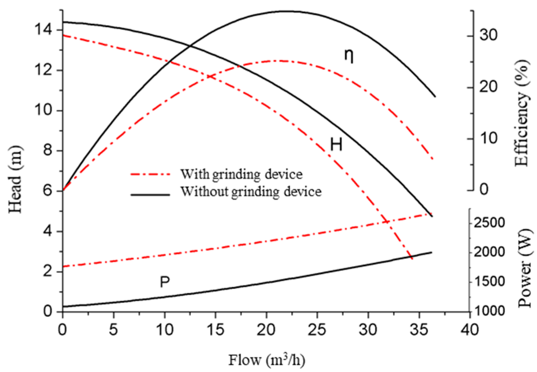
3.1. Influence of the Grinding Device on External Characteristics

Figure 10 shows the performance curve of the pump with or without a grinding device throughout the test. It can be seen from the figure that the head was able to reach 14.5 m when the flow rate was 0 without the grinding device. The flow rate at the highest efficiency point was 21.5 m3/h and the efficiency was 35.8%. After the grinding device was installed, both the head and the flow rate decreased. The head when the flow rate was 0 dropped to 13.7 m, which was 5.5% lower than that without a grinding device. The flow rate at the maximum efficiency point was 21.1 m3 /h, and the efficiency declined to 25.5%. Under the rated working condition (22 m3/h), the shaft power consumption was increased by about 700 W compared with that of the prototype without the grinding device. This is partly because the moving cutter head needed to consume a certain amount of power as the shaft rotated. Due to the water blocking effect of the cutter head, the hydraulic loss increased. In addition, after the pump was equipped with a grinding device, the flow area of the pump inlet was reduced. The increase in the flow rate near the cutter head increased the hydraulic loss. Therefore, the addition of a grinding device to the grinding pump greatly affected the performance of the pump, which caused the overall performance of the pump to decline.

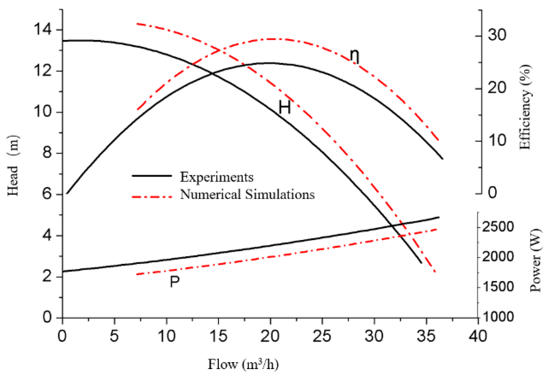
3.2. Comparison of Test Results and Numerical Simulation Prediction Results

Figure 11 shows the comparison between the test and the simulated external characteristic curve of the GSP-22 submersible grinder pump. It can be seen that when the flow rate was 0, the head was 13.7 m. The flow rate at the highest efficiency point was 21.1 m3/h, and the efficiency was 25.5%. It can be observed that there was a certain deviation between the simulation value and the test value of the prototype. The general performance of the simulation prediction was better than that of the prototype test, but the overall trend of the curves was consistent to a good degree. Since the numerical simulation only predicted the hydraulic efficiency of the fluid domain, only the hydraulic loss of the calculation domain was considered. In addition to the hydraulic loss, the actual grinding pump also included many losses such as leakage loss and mechanical loss. Therefore, the performance predicted by the simulation was higher than the performance of the actual submersible grinder pump in operation.
In fact, there are many reasons for the deviation between the numerical prediction and the experimental value. Firstly, some reasonable modeling simplification was adopted in the process of establishing the geometric model of the computational domain. When meshing, taking into account the quality of the mesh, the flow parts of the grinding pump are treated accordingly to promote convergence. Secondly, the turbulence model used in the numerical simulation was inconsistent with the turbulent flow in the actual pump. In addition, the dynamic reference coordinate model of dynamic and static coupling—that is, the multi-rotation coordinate model that assumes that each part of the fluid flows stably in different coordinate systems—is used to deal with the unsteady flow, which will bring certain deviations. All of these are reasons for the existence of errors.
Above all, the numerical simulation of the submersible grinder pump with the CFD software had a certain accuracy and reliability, which has important reference significance for further research on grinding pump optimization.

4. Numerical Results and Analysis

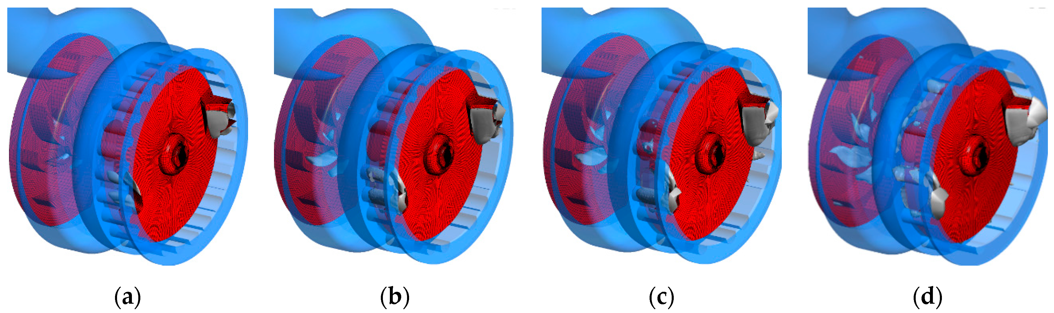
4.1. Cavitation Analysis of the Cutter Heads

Figure 12 shows the static pressure distribution, vapor volume fraction distribution and velocity near the cutter head on the middle section of the water body of the grinding pump with two cutter heads. It can be seen from the static pressure distribution diagram that the maximum pressure appeared in front of the cutter head, and the relative velocity of the fluid in this area is zero, which is called the stagnation point. The lower pressure area also appeared in the second half of the cutter head, and the corresponding lower pressure area also appeared in the semicircular flow channel of the static cutter head. From the absolute velocity vector diagram near the cutter head, it can be seen that the absolute velocity of the first half of the cutter head was larger due to the high-speed rotation of the cutter head. Due to the action of the pressure gradient, the direction of the velocity vector on the surface of the cutter head gradually pointed towards the low pressure area, and even the absolute velocity of the fluid in the area near the middle of the cutter head was opposite to the direction of the movement speed of the cutter head.

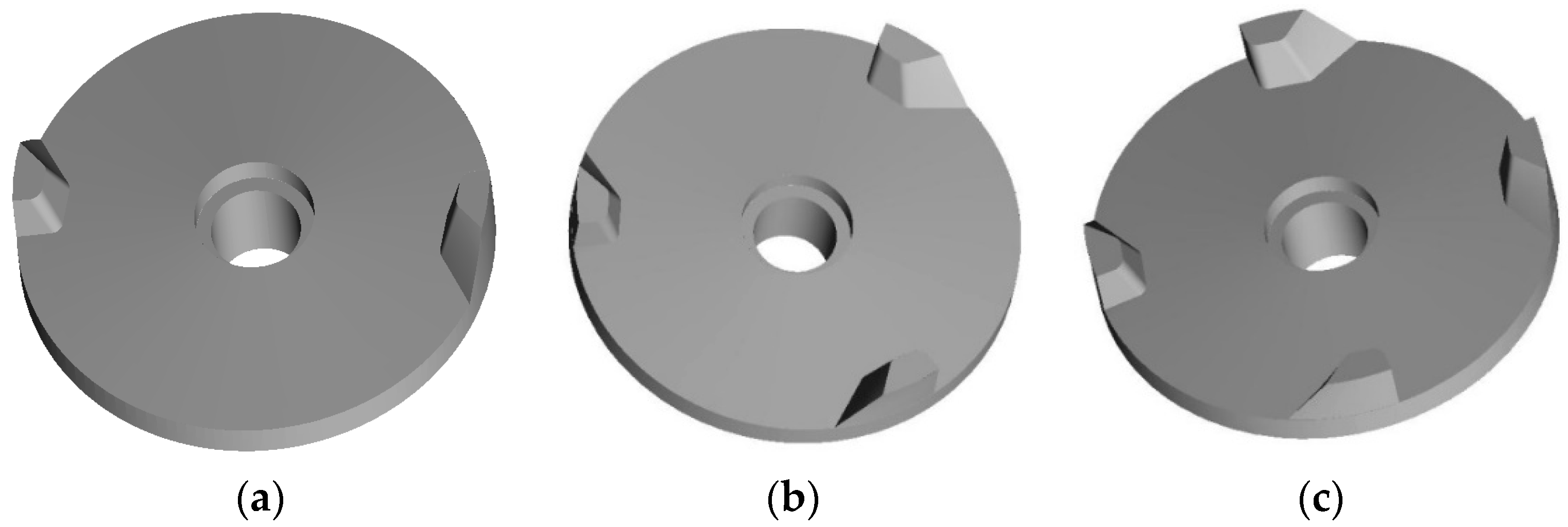
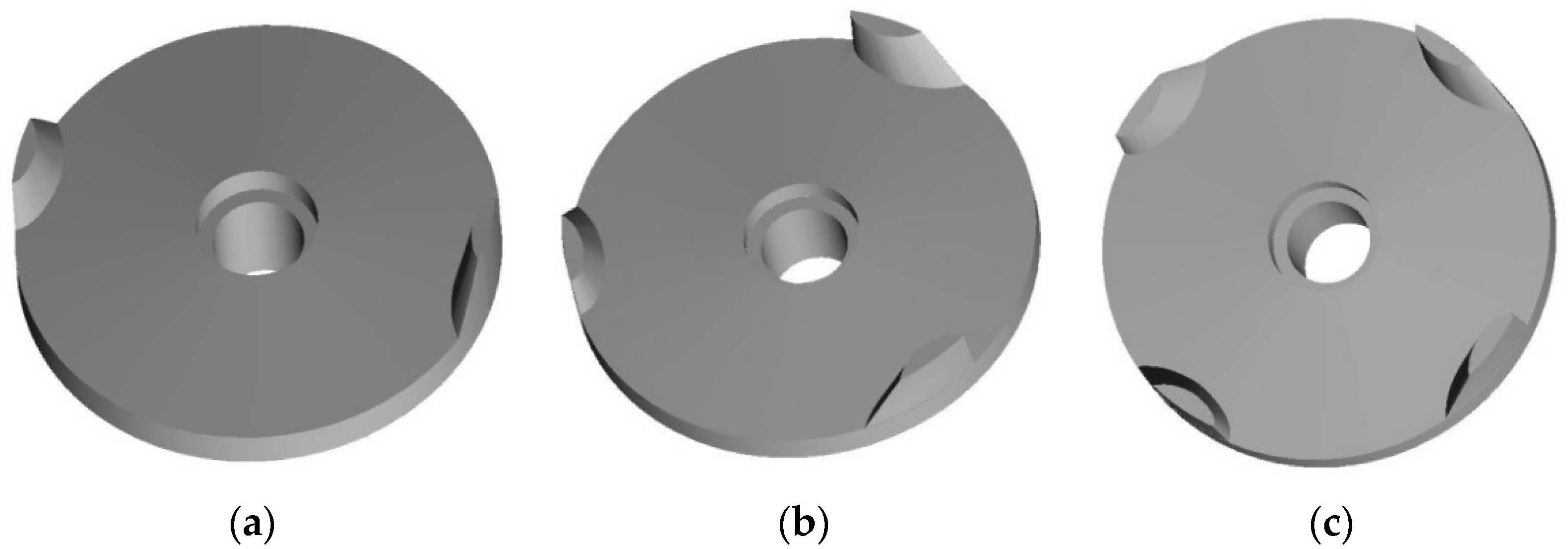
4.2. Determination of the Number of Cutter Heads

During the grinding test of the non-jammed submersible grinding pump, it could be observed that there was a white bubble band in the area near the cutter head, accompanied by a “swoosh” sound. The moving cutter head rotated at a high speed with the rotating shaft. The relative velocity of the fluid near the cutter head was high, and the flow was turbulent. In addition, the flow area near the cutter head was small, and cavitation was prone to occur. This effect will vary with the number of cutter heads. The number of cutter heads will also have a great impact on the cutting and grinding effect of the grinding pump. Thus, the number of cutting heads was the main factor affecting the performance of the grinding pump.
In order to analyze the influence of the number of moving cutter heads on the performance of the non-jammed submersible grinding pump, three models of grinding pumps with 2, 3 and 4 cutter heads were examined, as shown in Figure 13. Numerical simulations were carried out on five working points of the grinding pump with three types of cutter heads, respectively. The influence law of the radial clearance of the moving and static cutter discs on the performance of the non-jammed submersible grinding pump was discovered.

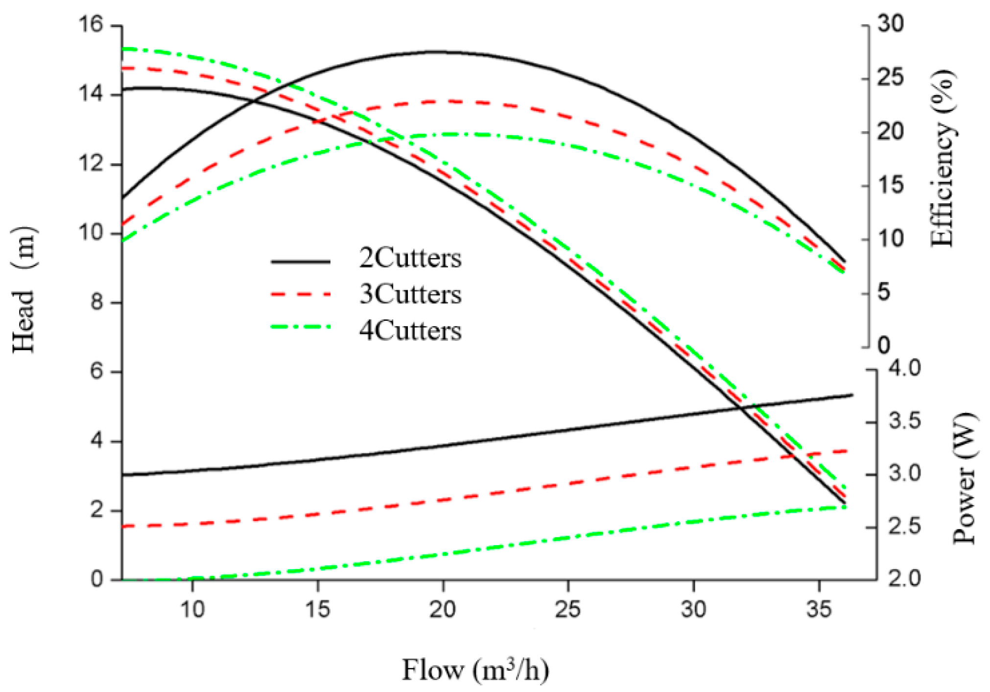
4.2.1. The Effect of the Number of Cutter Heads on the Performance of the Submersible Grinding Pump

Figure 14 shows the performance of the grinding pump when the number of moving cutter heads was 2, 3 and 4, respectively. It can be seen from the figure that under the same flow rate, the higher the number of moving cutter heads, the higher the pump head. This phenomenon occurred at each operating point, and the head of different cutter heads differed greatly under low flow conditions. This was mainly because with increases in the number of cutter heads, increasing the displacement at the pump inlet will increase the hydraulic loss; the cavitation of the cutter head at the grinding device is intensified and the loss at the grinding device is increased, resulting in a drop in the head of the submersible grinding pump.
It can be seen from Figure 14 that the shaft power of the grinding pump increased with increases in the flow rate; The shaft power of the grinding pump rose with increases in the number of moving cutter heads. The three shaft power curves were approximately parallel. The shaft power of the three-cutter head grinding pump was about 520 W larger than that of the two-cutter head pump at each working point. The shaft power of the four-cutter head grinding pump was higher than that of the three-cutter head grinding pump at each working point. The shaft power of the grinding pump was about 510 W. This is because the moving cutter head needs to consume a certain amount of power when it rotates with the shaft, and increases in the number of cutter heads will increase the hydraulic loss. Therefore, the number of grinding pump cutter heads has a great influence on the power of the pump shaft, which will cause sharp increases in the pump shaft power.
It can be observed from Figure 14 that the flow rate was around 21 m3/h when the efficiency of the grinding pump with different numbers of cutter heads reached the highest value. The highest efficiency of the grinding pump with two, three and four cutter heads was 27.91%, 23.05% and 20.34%, respectively. The efficiency decreased as a whole with increases in the number of cutter heads at each working point—especially the highest efficiency point. With regard to the pump head, it dropped to a certain extent with the increases in the number of cutter heads. The drop was larger under the condition of low flow. The shaft power of the grinding pump was about 520 W larger, and the shaft power of the four-cutter head grinding pump was about 510 W larger than that of the three-cutter head grinding pump; the efficiency of the pump decreased as a whole with increases in the number of cutter heads at each operating point. It can be seen that the number of cutter heads in the grinding pump moving cutterhead had a great effect on the performance of the grinding pump. With increases in the number of cutter heads, the power of the grinding pump will increase and the efficiency will decrease. Therefore, under the premise of ensuring the cutting and grinding effect, the number of cutter heads should be selected to be as low as possible.

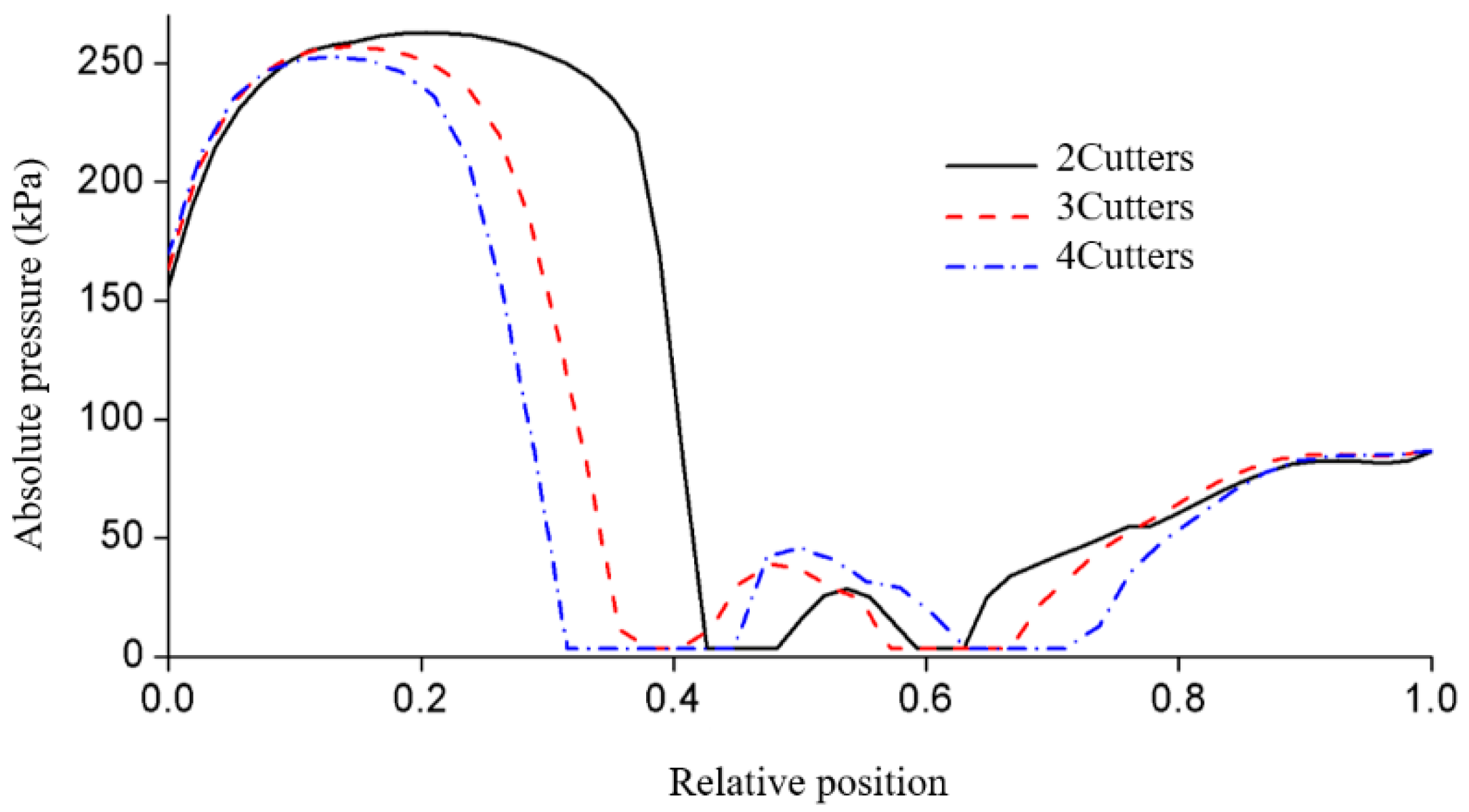
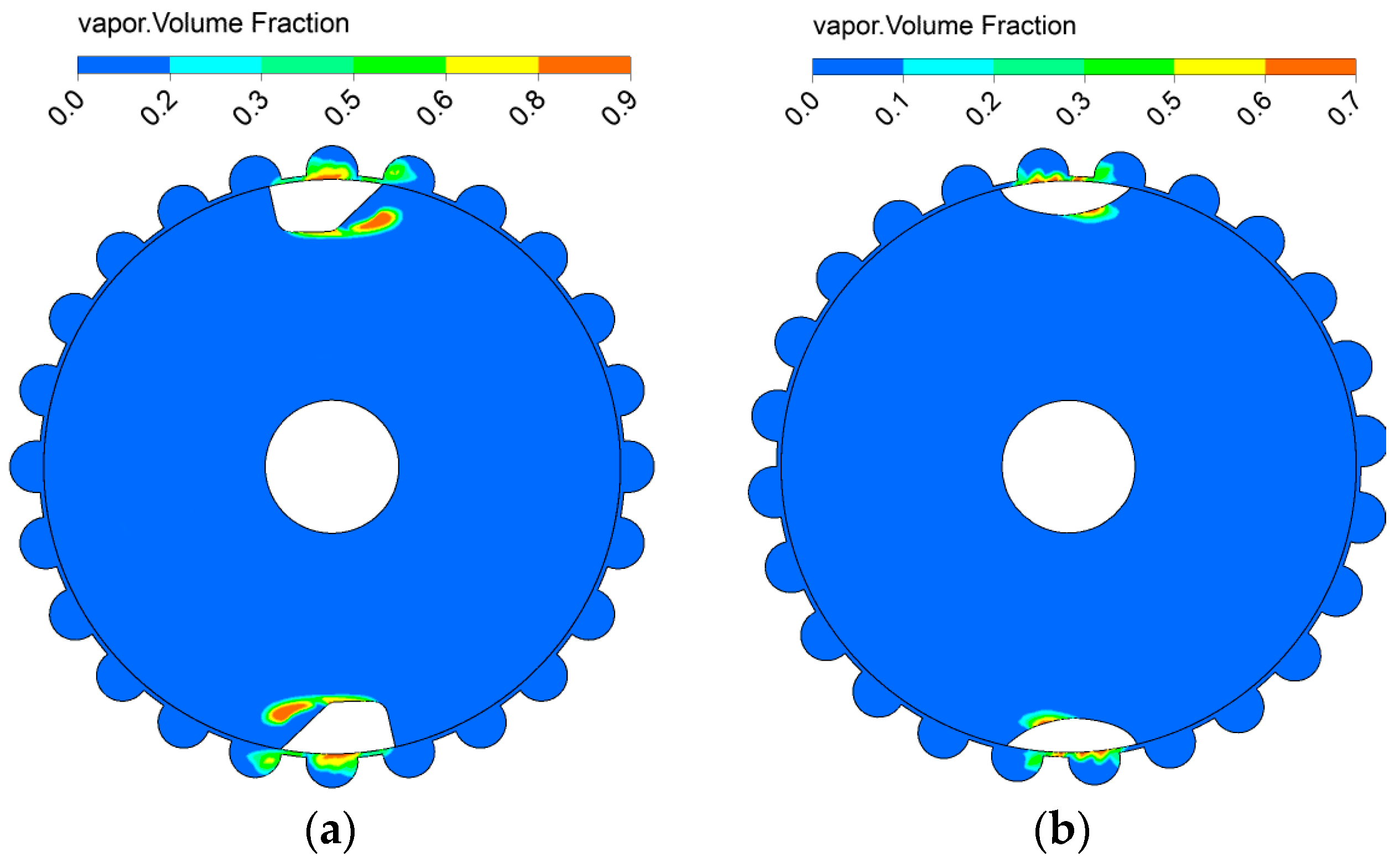
4.2.2. Influence of the Number of Cutter Heads on Cutter Head Cavitation

For the submersible grinding pump, the higher the number of cutter heads in the moving cutter head, the more times it can cut and grind sundries over the same length of time, and the corresponding grinding effect is better. However, changes in the number of cutter heads have a great influence on the performance of the grinding pump and the cavitation of the cutter head.
Figure 15 shows the distribution cloud map of the volume fraction of the vapor on the middle section of the water body of the two, three, and four cutter heads, respectively. The area with the higher vapor volume fraction was distributed near the cutter head—this means that cavitation occurred near the cutter head, which is basically consistent with the cavitation area near the cutter head in the grinding effect test. The area with the higher vapor volume fraction was the cavitation area, which is more consistent with the area with lower pressure. There were two main sites where cavitation occurred near the cutter head: The first site was in the rear half of the cutter head, which was caused by the bad shape of the wing; airfoil cavitation was caused by the high-speed rotation of the cutter head, the relatively large flow velocity near the cutter head—resulting in low pressure—and the poor shape of the cutter head. The second site was in the gap between the dynamic and static cutter discs; gap cavitation was caused by drops in pressure due to high flow velocity in the gap.
It can be seen from the figure that with increases in the number of cutter heads, the airfoil cavitation area in the middle and rear of the cutter head gradually became larger, but the area of clearance cavitation did not change much. This is because when the number of cutter heads increases, the expulsion effect of the cutter head on the water increases, and the relative flow rate increases accordingly, which eventually leads to a larger airfoil cavitation near the cutter head.
Figure 16 shows the variation trend of the surface pressure of the cutter head from the inlet side to the outlet side when the number of cutter heads was two, three and four, respectively. In all three cases, the pressure near the cutter head x/X = 0.4 and x/X = 0.6 reached the vaporization value of 3574 Pa, which implies that cavitation may have occurred near the two above sites. This corresponds to the cloud map of the vapor volume fraction distribution. It can be seen that with increases in the number of cutter heads, the area where the absolute pressure of the cutter head surface was at the vaporization pressure of 3574 Pa also gradually increased.
To sum up, with increases in the number of cutter heads, the expulsion effect of the cutter head on water increased, and the relative flow rate near the cutter head increased correspondingly—which eventually led to aggravated cavitation near the cutter head of the grinding pump. Therefore, under the premise of ensuring the cutting and grinding effect, the number of cutter heads should be selected to be as low as possible.

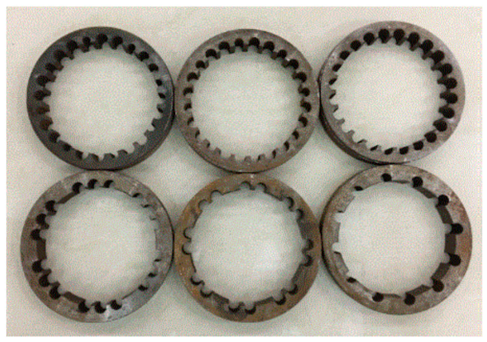
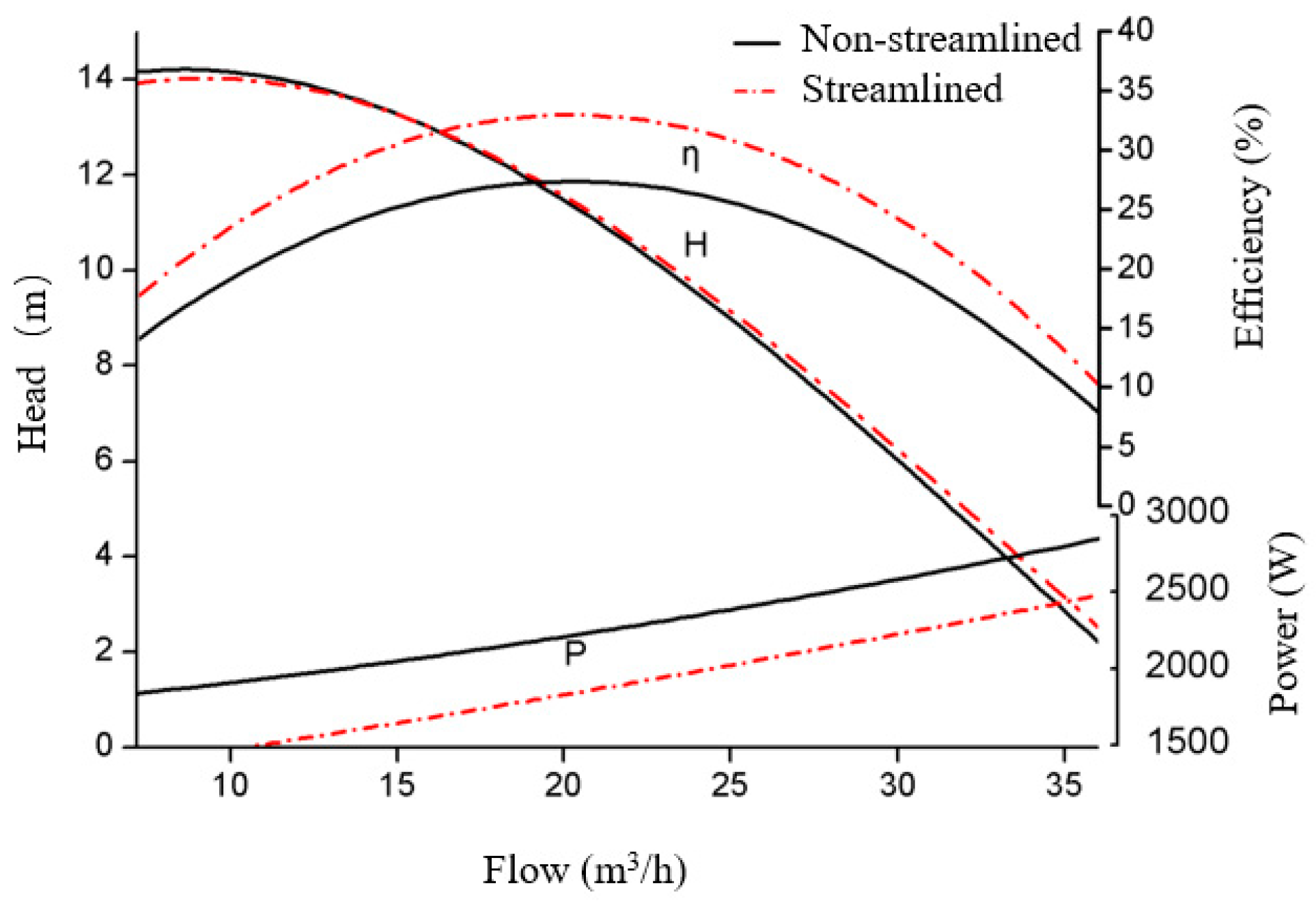
4.3. Optimization of Cutter Head Shape

Through the above research, it can be seen that the cavitation near the cutter head of the GSP-22 pump had two components: the clearance cavitation between the radial clearance of the dynamic and static cutter discs and the airfoil cavitation caused by the poor shape of the cutter head. Therefore, it is of great significance to optimize the shape of the cutter head and to control the airfoil cavitation near the cutter head.
In order to control the cavitation of the cutter head, the most ideal cutter head shape is streamlined. To ensure the sufficient strength of the cutter head, its shape was designed based on the 791 airfoil, which has good hydraulic performance. The top section of the cutter head was 0.75 times the root section, narrowing evenly from the root to the top. The final design of the moving cutter head is shown in Figure 17.
The cavitation of the submersible grinder pump GSP-22 with two, three and four cutter heads was studied, respectively, and the performance of the submersible grinding pump before the optimization of the cutter head was compared and analyzed. The inlet pressure was set to 1.1 atm and the outlet flow to 22 m3/h.

4.4. Performance Comparison of Different Cutter Head Shapes

Figure 18 shows the performance comparison of the GSP-22 pump with two different cutter head shapes, which were streamlined cutter head and non-streamlined cutter head-shaped, respectively. It can be seen from the figure that when the flow rate was less than 15 m3/h, the head of the streamlined cutter head grinding pump was higher than that of the non-streamlined cutter head; when the flow rate was greater than 15 m3/h, the head of the streamlined cutter head grinding pump was lower than that of the non-streamlined cutter head. The maximum efficiency of the streamlined cutter head grinding pump was 33.1%, while the maximum efficiency of the non-streamlined cutter head grinding pump was 27.5%. The maximum efficiency was increased by nearly 6% after changing to a streamlined cutter head. It can be seen that the overall power of the streamlined cutter head was lower than that of the non-streamlined cutter head. When the flow rate was 7.2 m3/h, the power of the streamlined cutter head grinding pump and the non-streamlined cutter head grinding pump were 1566.3 W and 1990.4 W, respectively. The power of the streamlined cutter head was 426.09 W—lower than that of the non-streamlined cutter head. When the flow rate was 36 m3/h, the power of the streamlined cutter head grinding pump and the non-streamlined cutter head grinding pump were 2344.1 W and 2702.1 W, respectively, with a difference of 357.98 W. The corresponding power of the non-streamlined cutter head was more than 13.2% higher than that of the streamline cutter head. This is because after the shape of the cutter head is streamlined, the corresponding displacement effect of the cutter head is reduced. The hydraulic loss and power consumed on the cutter head is therefore reduced, which results in the improvement in its efficiency.
The analysis showed that the performance of the grinding pump had been greatly improved in general by changing the shape of the cutter head to streamlined. For the head of the streamlined cutter head, the change was not very large; however, the power of the grinding pump was reduced by more than 13.2%, and the maximum efficiency of the grinding pump was increased by 6%.

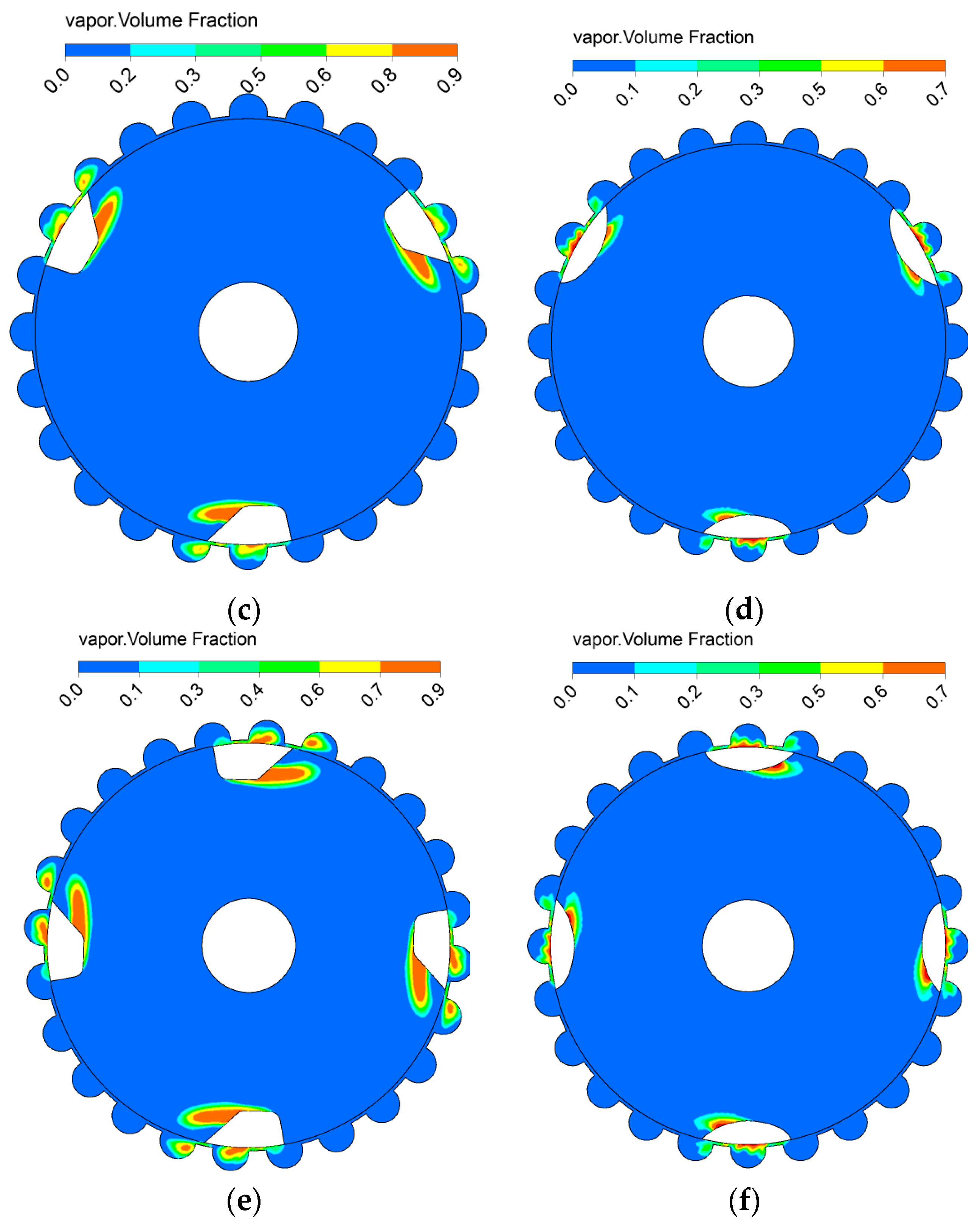
4.5. Streamlined Cutter Head Cavitation with Different Numbers of Cutter Heads

Figure 19 shows the comparison of the cavitation of the submersible grinding pump with two, three and four streamlined and non-streamlined cutter heads, respectively. For different numbers of cutter heads, the streamlined cutter head was smaller than the bluff cutter head, whether measured by the gas volume fraction or the size of the gas distribution area. That is to say, the shape of the cutter head was changed to a streamlined shape, which can effectively control the strength of cavitation near the cutter head.

5. Experimental Verification

5.1. Cavitation Phenomenon

The grinding effect test of the grinding pump was carried out in a pool with a transparent window. The test pool is shown in Figure 20a. During the test, the prototype was positioned in the pool, and the water in the pool was deep enough to cover the motor. The camera recorded the process of grinding debris through the transparent window. The outlet of the grinding pump was covered with a flange plate with a small hole. The hole diameter was determined via calculations, and the small hole diameter was used to control the flow rate during the prototype test. The back of the flange plate was wrapped with a filter screen to collect the sundries discharged from the grinding pump. After the grinding pump was started and ran stably, the grinding test objects were placed in the inlet area. The sundries were sucked into the submersible grinding pump for grinding and discharge.
In order to limit the size of the particles passing through the submersible grinding pump, the flow area where the cutter head and the static cutter head cooperate was composed of several semicircular flow channels and radial gaps between the dynamic and static cutter heads. The moving cutterhead rotated at high speed with the pump shaft, and the liquid velocity near the cutter head was relatively large. Hence, cavitation was prone to occur near the cutter head; it had a bad influence on the inlet flow state of the grinding pump, thereby affecting the performance of the grinding pump. This phenomenon could be clearly seen in the process of the grinding effect test, as shown in Figure 20b, which was the cavitation phenomenon observed during the test. It was accompanied by a “buzz” sound.
Cavitation near the cutter head can cause cavitation damage to the cutter head and affect the normal operation of the grinding pump. The impact of this is multi-faceted. Firstly, cavitation can interfere with the exchange of liquid energy in the grinding pump, causing a decrease in the external performance of the pump. The characteristic performance is decreased, or the flow may even be cut off. Secondly, cavitation will lead to large pressure pulsation, which is likely to induce vibration and noise in the grinding pump. Moreover, the bubbles generated by cavitation could suddenly collapse, and the liquids collide with each other in an instant. The metal surface of the cavitation part would be destroyed if this occurred.

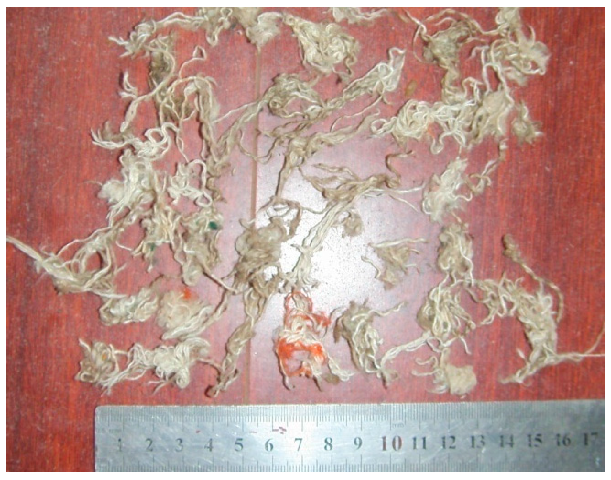
5.2. Grinding Effect Test of the Submersible Grinding Pump

Non-jammed submersible grinding pumps are widely used in hospitals, hotels, domestic sewage discharge and rainwater discharge. According to the working environment of the submersible grinding pump, cotton gloves or chicken bones are selected as the test objects for the grinding effect test of prototypes. The grinding effect of cotton gloves is shown in Figure 21. Through the grinding effect test, the prototype machine was able shred cotton gloves, sanitary napkins and chicken bones without entanglement or clogging, and the grinding effect was acceptable.

6. Conclusions

(1)
With increases in the number of cutter heads, the expulsion effect of the cutter head on water increases, and the relative flow rate near the cutter head increases accordingly—which eventually leads to aggravated cavitation near the cutter head of the grinding pump.
(2)
The head change in the submersible grinding pump with the streamlined cutter head was not considerable; however. the power was reduced by more than 13.2% as a whole, and the maximum efficiency value was increased by 6%.
(3)
For streamlined cutter heads with different numbers of cutter heads, the streamlined cutter head was smaller than the bluff cutter head, regardless of the volume fraction of the gas or the size of the gas distribution area. Therefore, the shape of the cutter head was changed to a streamlined shape, which could effectively control the strength of cavitation near the cutter head.
In summary, in the design process of the grinding pump, while increasing the number of cutter heads to obtain a higher grinding effect, the influence of the number of cutter heads on the cavitation performance of the pump should also be considered. Additionally, changing the shape of the cutter head to streamlined can increase the efficiency of the pump and improve the cavitation performance without affecting the head.

Author Contributions

Formal analysis, Z.W. and Q.F.; Methodology, R.Z. and Y.L.; Resources, R.Z., Z.W. and Y.L.; Writing—original draft, Z.Q. All authors have read and agreed to the published version of the manuscript.

Funding

This work was funded by National Youth Natural Science Foundation of China (51906085). China Postdoctoral Science Foundation Funded Project (2019M651734). Jiangsu Province Innovation and Entrepreneurship Doctor Project (2019). Zhejiang Postdoctoral Project (2019). The NSFC (Natural Science Foundation of China) (U20A20292). Project of State Key Laboratory of mechanical system and vibration (MSV202203).

Institutional Review Board Statement

Not applicable.

Informed Consent Statement

Not applicable.

Acknowledgments

Thanks to Jiangsu University for its support in this experiment and to Li Yajie for her help in English writing.

Conflicts of Interest

The authors declare no conflict of interest.

References

  1. Guan, X. Modern Pumps Theory and Design; China Astronautic Publishing House: Beijing, China, 2011. (In Chinese) [Google Scholar]
  2. Shi, W.D.; Sang, Y.M.; Wang, Z.; Liu, H.L.; Zhang, Q.H. Development and prospect of non-clogging pump with high-efficiency. Drain. Irrig. Mach. 2006, 24, 48–52. (In Chinese) [Google Scholar]
  3. Guan, X.; Zhang, T.; Wei, D.; Wen, X. Advances in non-clogging pumps. Drain. Irrig. Mach. 2003, 21, 1–4. (In Chinese) [Google Scholar]
  4. Wang, X.; Lu, Y.; Zhu, R.; Fu, Q.; Zhong, W. Study of hydraulic performance and pressure pulsation characteristics of the grinder pump in case of clogging. Bulg. Chem. Commun. 2016, 48, 87–95. [Google Scholar]
  5. Fu, Q.; Lu, Y.; Zhu, R.; Wang, X.; Wang, X. Cavitation and pressure pulsation characteristics of a non-jammed submerged grinder pump. J. Vib. Shock 2016, 35, 95–101. [Google Scholar]
  6. Zhang, N.; Gao, B.; Li, Z.; Jiang, Q. Cavitating flow-induced unsteady pressure pulsations in a low specific speed centrifugal pump. R. Soc. Open Sci. 2018, 5, 180408. [Google Scholar] [CrossRef] [PubMed] [Green Version]
  7. Long, Y.; Zhu, R.; Wang, D. A Cavitation Performance Prediction Method for Pumps PART1-Proposal and Feasibility. Nucl. Eng. Technol. 2021, 52, 2471–2478. [Google Scholar]
  8. Yun, L.; Yan, Z.; Jianping, C.; Rongsheng, Z.; Dezhong, W. A Cavitation Performance Prediction Method for Pumps PART2-Sensitivity and Accuracy. Nucl. Eng. Technol. 2021, 53, 3612–3624. [Google Scholar] [CrossRef]
  9. Long, Y.; An, C.; Zhu, R.; Chen, J. Research on hydrodynamics of high velocity regions in a water-jet pump based on experimental and numerical calculations at different cavitation conditions. Phys. Fluids 2021, 33, 045124. [Google Scholar] [CrossRef]
  10. Qiu, N.; Zhou, W.; Che, B.; Wu, D.; Wang, L.; Zhu, H. Effects of microvortex generators on cavitation erosion by changing periodic shedding into new structures. Phys. Fluids 2020, 32, 104108. [Google Scholar] [CrossRef]
  11. Qiu, N.; Zhu, H.; Long, Y.; Zhong, J.; Zhu, R.; Wu, S. Assessment of Cavitation Erosion in a Water-Jet Pump Based on the Erosive Power Method. Scanning 2021, 2021, 5394782. [Google Scholar] [CrossRef] [PubMed]
  12. Huang, R.; Ji, B.; Luo, X.; Zhai, Z.; Zhou, J. Numerical investigation of cavitation-vortex interaction in a mixed-flow water-jet pump. J. Mech. Sci. Technol. 2015, 29, 3707–3716. [Google Scholar] [CrossRef]
  13. Huang, R.; Dai, Y.; Luo, X.; Wang, Y.; Huang, C. Multi-objective optimization of the flush-type intake duct for a waterjet propulsion system. Ocean Eng. 2019, 187. [Google Scholar] [CrossRef]
  14. Xu, S.; Long, X.; Jin, B.; Li, G. Investigation on the mechanism between vortex and cavitation in an axial water-jet pump. J. Harbin Eng. Univ. 2020, 41, 951–957. [Google Scholar]
Figure 1. Static cutter models with different degrees of clogging [4].
Applsci 12 06112 g001
Figure 2. Cavitation distribution inside a grinder pump at different degrees of blockage [5]. (a) Non Clogging, (b) 1/4 Clogging, (c) 1/3 Clogging, (d) 1/2 Clogging.
Applsci 12 06112 g002
Figure 3. Cavitation performance and Cavitating flow structures of a centrifugal pump [6].
Applsci 12 06112 g003
Figure 4. Cavitation and high-velocity vortex interaction [9].
Applsci 12 06112 g004
Figure 5. Non-jammed submersible grinder pump.
Applsci 12 06112 g005
Figure 6. Water body assembly and test cutter. (a) Water body assembly, (b) Test cutter disk.
Applsci 12 06112 g006
Figure 7. Grid-independent test curve.
Applsci 12 06112 g007
Figure 8. Flow components and assembly grid. (a) Impeller, (b) Static cutter and rear channel, (c) Moving cutter, (d) Inlet, (e) Volute, (f) Assembly.
Applsci 12 06112 g008
Figure 9. A schematic diagram of the test device. (1) Test pump, (2) Pressure measuring tube, (3) Flowmeter, (4) Valve.
Applsci 12 06112 g009
Figure 10. The effect of the grinding device on the performance of the grinding pump.
Applsci 12 06112 g010
Figure 11. Comparison of simulation prediction and test results.
Applsci 12 06112 g011
Figure 12. Sectional flow distribution of cutter. (a) Static pressure distribution, (b) Vapor volume fraction distribution, (c) Absolute velocity near the cutter head vector illustration.
Applsci 12 06112 g012
Figure 13. Moving cutter head with different numbers of cutter heads. (a) 2 cutter heads, (b) 3 cutter heads, (c) 4 cutter heads.
Applsci 12 06112 g013
Figure 14. Pump performance curve with different numbers of cutter heads.
Applsci 12 06112 g014
Figure 15. Vapor volume fraction of the cutter midsection with different numbers of cutter heads. (a) 2 cutter heads, (b) 3 cutter heads, (c) 4 cutter heads.
Applsci 12 06112 g015
Figure 16. Surface pressure distribution of the different numbers of cutter heads.
Applsci 12 06112 g016
Figure 17. Streamlined cutter head of different numbers. (a) 2 cutter heads, (b) 3 cutter heads, (c) 4 cutter heads.
Applsci 12 06112 g017
Figure 18. Pump performances comparing streamlined cutter head with non-streamlined cutter head.
Applsci 12 06112 g018
Figure 19. Cavitation compared different number of streamlined cutter head with non-streamlined. (a) non-streamlined 2 cutter head, (b) streamlined 2 cutter head, (c) non-streamlined 3 cutter head, (d) streamlined 3 cutter head, (e) non-streamlined 4 cutter head, (f) streamlined 4 cutter head.
Applsci 12 06112 g019aApplsci 12 06112 g019b
Figure 20. Cutter cavitation test. (a) test water tank, (b) Cutter cavitation.
Applsci 12 06112 g020
Figure 21. Grinding effect on cotton gloves.
Applsci 12 06112 g021
Publisher’s Note: MDPI stays neutral with regard to jurisdictional claims in published maps and institutional affiliations.

