1. Introduction
Threaded joints account for approximately half of all joints produced in mechanical systems. They are prevalent across all fields of industry. Internal threads have a wide variety of sizes, depths, and shapes, including thru-bores, such as a nut, and blind-end internal threads. Threaded joints offer easy assembly and disassembly of systems, and are important for maintenance and recycling purposes. Both external threads and their internal counterparts have been comprehensively studied over many years.
The examination methods used for this purpose can be divided into contactless examination and contact-based examination. Contactless examination commonly utilizes eddy currents, lasers, or cameras. In [
1,
2], the authors utilized laser sensors for non-contact inspection of threads. In [
3,
4], the authors conducted optical examination of screw threads utilizing cameras. The authors of [
5] addressed an Optical Thread Plug Gauge (OTPG) for internal thread examination utilizing cameras. A sequence of partial wall images of an internal thread were retrieved and reconstructed into a 2D unwrapped image. Then, a digital image processing and classification procedure was utilized to normalize, segment, and determine the quality of the internal thread. The authors of [
6] experimented with 3D scanners and their application to measurement of large threads. A laser-optical internal thread measurement system was discussed in [
7]. The authors of [
8] addressed tubing-based thread testing equipment based on magnetic flux leakage theory. In order to examine tiny surface fatigue cracks, ref. [
9] utilized eddy current testing, which is an electromagnetic method. For detection of steel surface defects, refs. [
10,
11,
12] utilized camera images and then applied deep learning approaches to the images.
Contactless examination can detect various faults in a time-efficient manner. Despite its speed, contactless examination has a major disadvantage in that it cannot ensure that the mating parts will assemble together correctly [
13].
Recently, refs. [
14,
15] tackled examination of external threads using a contact scanning probe. In [
15], a model was established for a special probe of a 3D thread-measuring machine. In [
14], the influence of the geometric error of a contact probe on the accuracy of external thread measurement was investigated in order to improve the measurement accuracy of the thread measuring machines.
This paper considers only the examination of internal threads, not external threads. We consider examination of a Thread Hole (TH) via contact with the TH. In the process of making THs, faulty holes may be generated. The proposed Inspection Device (ID) has a screw shape, enabling it to smoothly assemble with a TH without faults.
If the ID and a TH have distinct threads, then they cannot be joined accurately. For instance, an examined TH can have cracks or delamination in its composites, and can thus have threads that are different from those of the ID. A TH fault can be detected by observing the torque generated while tightening the ID through the TH.
Under contact-based examination methods, successful assembly of the gauged part (with its mating part) is assured [
13]. Hence, many companies, such as BEHCO [
16] and Newvistacorp [
13], have developed commercial contact-based examination systems. However, these companies do not make the detailed structure of their products public.
In this article, we propose a contact-based examination system using simple hardware. We present details of the developed examination system and develop a simple hardware design to generate the ID’s axial motion from the motor’s rotational motion. A simple design such as the one proposed here is desirable in light of its positive effects on both system maintenance and costs.
As the ID must be used many times, the arrangement error between its axis and the TH can increase with time and use, which decreases examination accuracy. Thus, a buffer with springs is utilized to overcome instances where the TH is not accurately arranged with the axis of the ID.
In our examination system, a camera is further utilized to automatically estimate the TH size. Based on the TH size measurements, the examination system automatically sets the torque threshold that is optimal for the size of the examined TH. In this way, the examination accuracy can be improved irrespective of TH size.
The contributions of the present paper are summarized as follows. To the best of our knowledge, the proposed examination method is novel in following aspects:
We address a simple hardware design generating the ID’s axial motion from the motor’s rotational motion;
A buffer with springs is utilized to overcome instances where the TH is not accurately arranged with the ID’s axis;
Utilizing a camera, the size of the TH is estimated automatically. Then, the TH is examined using the torque threshold that is optimal for the examined TH size. In this way, holes of various sizes can be examined both adaptively and optimally.
Note that above three aspects do not hold for commercial examination systems from companies such as BEHCO [
16] or Newvistacorp [
13]. Furthermore, these companies do not make public the detailed structure of their products.
To the best of our knowledge, our paper is novel in examining THs of various sizes by adaptively setting the torque threshold which is optimal for the examined TH. In the present paper, we verify the performance of the proposed examination system through experiments.
The rest of the article is organized as follows:
Section 2 presents the examination process used by the proposed system;
Section 3 addresses the experiments used to verify the proposed examination system; finally, our conclusions are presented in
Section 4.
2. Automatic TH Examination
We used an AC servo motor (Mitsubishi, MR-JE-A) able to measure the torque in real time. Our examination system examines a TH by observing the torque that is generated while tightening the ID through the TH. When the examination system is initiated, the system operator designates the revolutions and the torque threshold, , of the servo motor. The examination system examines a TH while rotating by the designated revolutions, which are set by the operator. If the torque measured in the servo motor is greater than during this designated rotation, then this large torque implies that a faulty TH has been detected.
We first introduce the hardware design of the proposed examination system. A photo of the entire system is provided in
Figure 1. The proposed design has two components, the approaching component and the ID component. The model of the entire system is plotted in
Figure 2, with the approaching component and ID component marked as rectangles with distinct colors.
2.1. Approaching Component
The model of the approaching component is depicted in the red rectangle in
Figure 2. The approaching component controls the up and down motion of the ID component.
2.2. ID Component
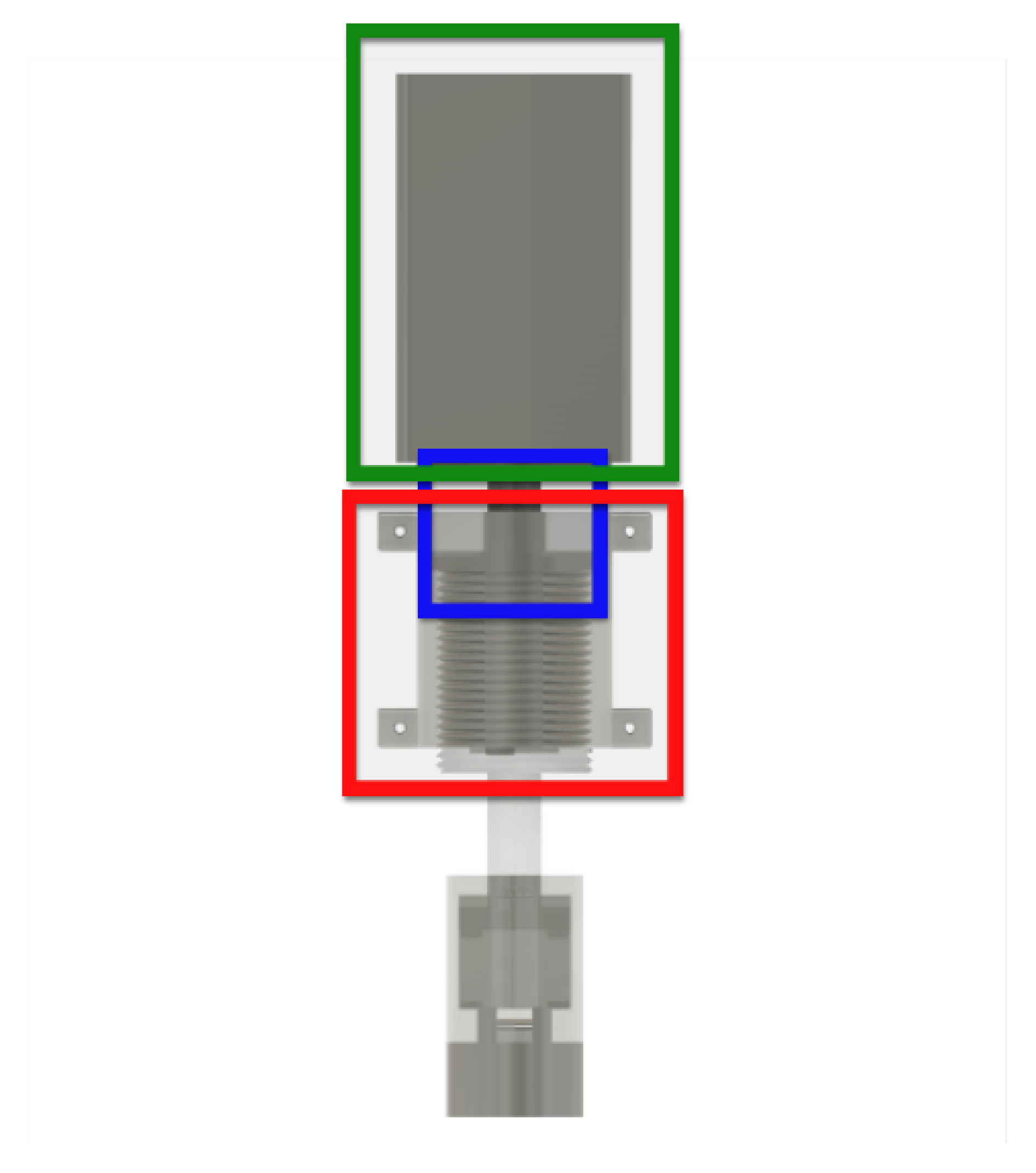
The model of the ID component is depicted in
Figure 3. In order to show the parts inside the ID component, the model is plotted translucently. The ID component has five parts: the servo motor, motor support, rotary shaft, ID shaft, and cover frame. The servo motor is depicted inside the green rectangle in
Figure 3. The servo motor controls the rotation speed while observing the torque in real time. The rotary shaft is depicted inside the blue rectangle in
Figure 3, while the cover frame is depicted inside the red rectangle. The ID shaft component generates the ID’s vertical motion from the rotational motion of the servo motor.
The model of the motor support is shown in
Figure 4. The motor support in
Figure 4 is located at the bottom of the servo motor in
Figure 3. The motor support is utilized to connect the ID component and the approaching component in
Figure 2.
Figure 5 shows the models of (a) the rotary shaft, (b) the cover frame, and (c) the ID shaft. The rotary shaft is connected to the motor’s rotor. The rotary shaft is depicted inside the blue rectangle in
Figure 3. The cover frame is depicted inside the red rectangle in
Figure 3. The rotary shaft and ID shaft are installed inside the cover frame. The ID shaft moves up and down inside the cover frame. The ID shaft generates the ID’s vertical motion from the motor’s rotational motion.
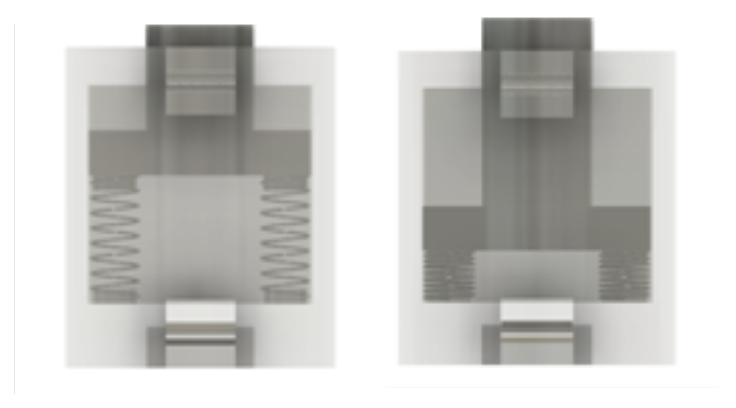
The model of the buffer with springs is depicted in
Figure 6. The left subplot in
Figure 6 shows an example of the case where the springs are stretched, while the right subplot in
Figure 6 shows an example of the case where the springs are compressed. The buffer is connected to the ID shaft, shown in (c) of
Figure 5. The buffer with springs is utilized to overcome instances where the TH is not accurately arranged with the ID’s axis.
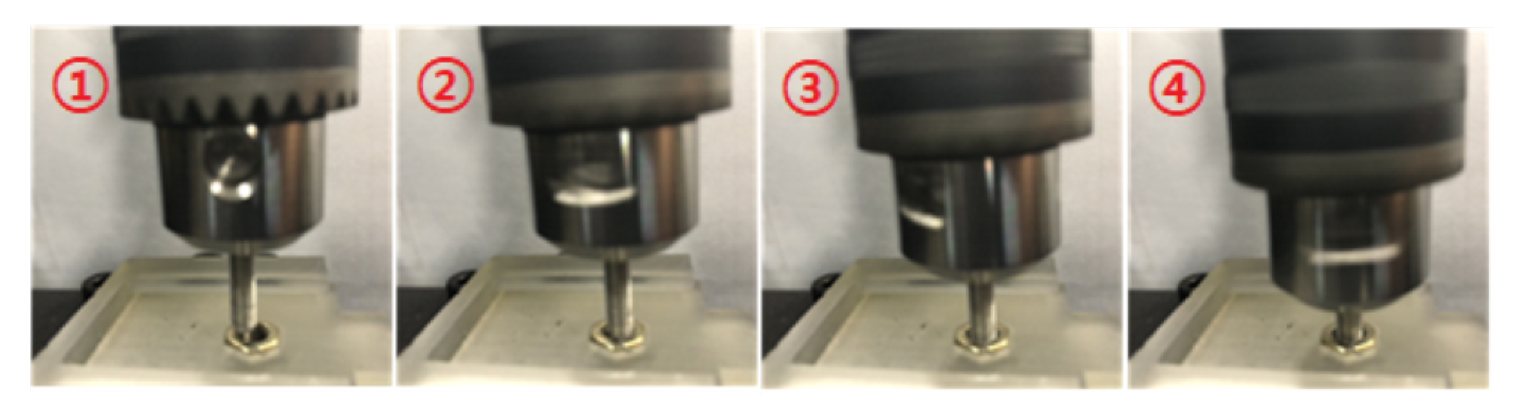
The buffer has springs in order to resolve any problems due to slight misalignment. Therefore, the motion of the ID shaft is slightly buffered. In this way, the ID shaft has flexibility even in instances where the TH is not arranged accurately. Utilizing the buffer with springs, the ID is able move through a slightly misaligned TH, as depicted in
Figure 7. In
Figure 7, the movement order is
.
The model of the drill chuck support is depicted in
Figure 8. The drill chuck support exists at the lower part of the ID component shown in
Figure 3. This support connects the buffer’s bottom to a commercial drill chuck. The drill chuck support is utilized to fix a commercial drill chuck tightly. By changing the ID in the drill chuck, it is possible to examine holes with various sizes.
2.3. Inspection Algorithm
The algorithm for controlling the servo motor inside the ID component is presented as Algorithm 1. The servo motor can measure the torque in real time. A programmable logic controller (PLC) is utilized for programming Algorithm 1. A PLC is an industrial computer that has been adapted for the control of manufacturing processes involving machines, robotics, or any similar activity that requires high reliability [
17].
When the ID is initiated, the operator designates the revolutions and of the servo motor inside the ID component. The ID examines the TH while rotating by the number of revolutions designated by the operator. If the torque during the examination is larger than , this indicates faults in the examined TH. When a faulty TH is detected, the ID reverses its revolving direction and returns to its initial position.
Algorithm 1 is utilized to examine a TH. In this algorithm, implies that the examined TH has faults, and implies that the examined TH has no faults.
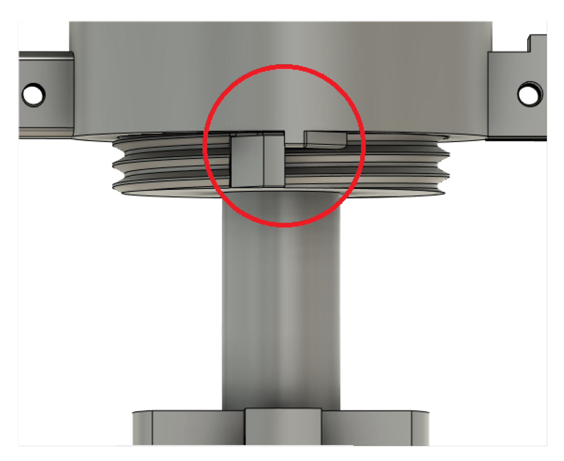
When an examination is completed, the ID shaft must return to its initial position. Thus, we installed two protective barriers, one on the cover frame and one on the ID shaft.
Figure 9 shows the model of the two protective barriers (the parts inside the red circle). These protective barriers are utilized to allow the ID shaft to return to its initial position whenever an examination is completed. In other words, these protective barriers remove any errors in the ID shaft’s initial position.
| Algorithm 1 Inspection algorithm |
- 1:
the revolutions which are set by the operator; - 2:
The servo motor begins revolving N times; - 3:
if the torque measured by the servo motor is bigger than AND the current revolution is then - 4:
The motor revolves times; - 5:
Return ; - 6:
end if - 7:
if the current revolution reaches N then - 8:
The motor revolves times; - 9:
Return ; - 10:
end if - 11:
The motor rotates with small speed; - 12:
if the torque measured by the motor is bigger than then - 13:
The motor reached the initial position; - 14:
end if
|
As the ID shaft returns to the initial position, the shaft rotates half a revolution less than the designated return rotation value (N or n in Algorithm 1). Thereafter, the motor rotates at low speed and stops at the moment when sufficient torque is applied due to the barriers on the cover frame and the ID shaft. The slowness of this motion reduces the strain on the protective barriers.
Figure 10 shows the model of the camera used in our examination system. The camera is connected to the cover frame shown in (b) of
Figure 5. The camera measures the TH in real time and estimates the TH size.
The camera utilizes a Raspberry Pi [
18] for estimating the size of the examined TH. In order to estimate the TH size from the camera image, template matching is applied using OpenCV [
19]. templates for every TH size are stored and matched with the TH from the camera’s measurements. By observing the similarity between a template and the TH from the camera measurements, the ID is able to estimate the size of the examined TH.
Figure 11 shows an example of a photo measured by the camera. The Region Of Interest (ROI) is depicted as a green circle.
Figure 11 shows that the TH image is inside the ROI. Template matching using OpenCV [
19] is applied to estimate the TH size in the ROI.
Figure 11 shows that the estimated size is M3, which is correct.
3. Experiments
In this article, we propose a TH examination system which is able to automatically examine TH fault states. In order to improve the examination system’s accuracy, it is desirable to set (the torque threshold) adaptively. In order to set adaptively, we examined various types of holes.
3.1. Experiment for Torque Threshold Setting
If is too low, then it is possible that a TH without faults may be detected as a faulty TH. If is too high, on the other hand, a faulty TH may not be detected correctly.
Accordingly, we performed experiments to measure the accuracy of the examination system while changing the torque threshold, . The experiments were conducted utilizing M3, M4, and M5 steel bolts and steel THs. Here, M3 has a diameter of 6 mm, M4 has a diameter of 8 mm, and M5 has a diameter of 10 mm. While the proposed examination system can be applied for other sizes of THs, the purpose of this experiment was to derive the optimal torque threshold associated with each hole size.
The experiments were conducted ten times each with M3, M4, and M5 steel bolts and steel THs of the following four types: faultless THs, thread-free holes, faulty THs, and small THs. Each bolt (M3, M4, and M5 bolts) were used to examine various types of THs 60 times in total.
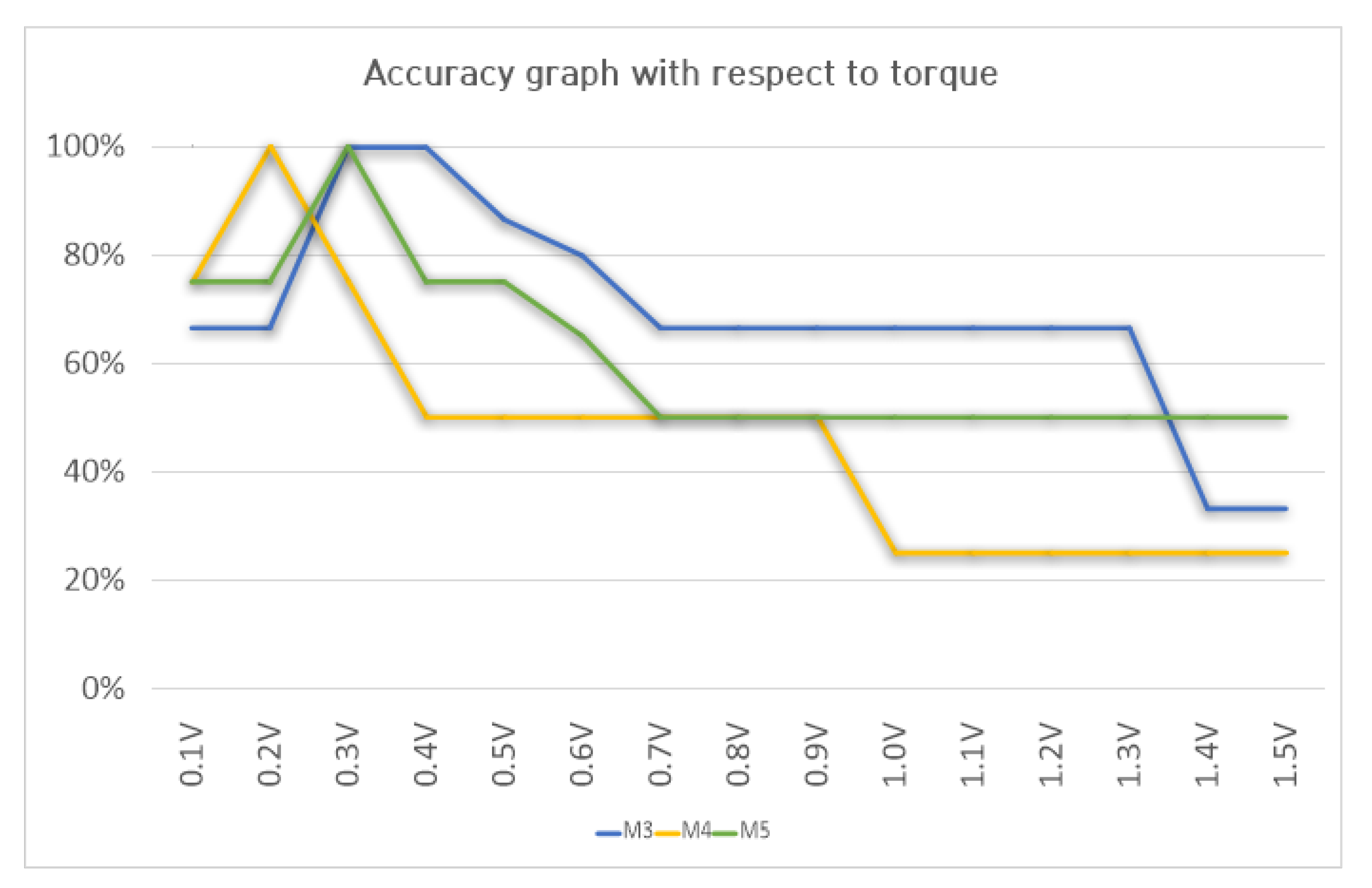
Figure 12 shows the accuracy graph (in percent) with different
. For instance,
n percent with M3 indicates that among all 60 experiments using M3,
cases succeeded in examining of the associated hole.
The experimental results shown in
Figure 12 indicate that for the M3, M4, and M5 holes, the highest accuracy was with the torque threshold set as 0.3 V–0.4 V, 0.2 V, and 0.3 V, respectively (Note that V (voltage) is the unit used for torque measurements in the AC servo motor).
3.2. Setting the Optimal Torque Threshold Adaptively by Observing the TH Size
We derived the optimal torque threshold
for TH size through experiments, as shown in
Figure 12. The camera is utilized to estimate the size of an examined TH. Then, the operator can set the optimal
associated with each measured TH size.
The camera estimates the TH size, allowing the examination to be conducted utilizing the optimal torque threshold
associated with the examined TH size. In order to find the optimal
for the examined TH size, we utilized the experiments presented in
Figure 12.
This paper proposes setting the optimal torque threshold associated with the examined TH size. Here, the camera is used to measure the size of the examined TH. In cases where the proposed approach is not used, a fixed threshold can be applied irrespective of the size of the examined TH.
For comparison with the proposed approach, we performed experiments utilizing a fixed torque threshold (
V). These experiments were conducted twenty times each with M3, M4, and M5 steel bolts.
Figure 13 depicts the accuracy graph of the optimal torque threshold (Optimal) and fixed torque threshold (Fixed). A fixed torque threshold of
V was utilized as the fixed torque threshold (Fixed).
Figure 13 indicates that applying the optimal torque threshold is more accurate compared to the case where a fixed torque threshold (
V) was utilized.
4. Conclusions
This paper presents a contact-based examination system which examines TH faults by screwing through the TH. The examination system measures the torque while tightening the ID in order to detect any TH faults. A buffer with springs is utilized to overcome instances where the TH is not accurately arranged with the ID’s axis.
Adaptively applying the optimal torque threshold leads to accurate examination of THs with various sizes. Utilizing a camera, the examination system automatically measures the TH size and sets the optimal torque threshold for the examined TH. Experiments were conducted in order to demonstrate the effectiveness of the proposed examination system.
In this paper, we address the examination of a steel TH using a steel bolt. In the future, we intend to address the examination of holes with various other materials.
In our paper, the servo motor is used to measure the torque in real time. In the future, the servo motor could be replaced by a cheaper DC motor in order to further reduce the cost of the examination system. Furthermore, a PLC is not necessary for controlling a DC motor. In order to measure the torque using the DC motor, encoders can be installed on the DC motor. As the rotation speed of the DC motor decreases when torque is applied to the motor, the rotation speed of the DC motor can then be used to measure the torque in real time.


