Review

Gyrotrons as High-Frequency Drivers for Undulators and High-Gradient Accelerators

1
Institute of Electronics, Bulgarian Academy of Sciences, 1784 Sofia, Bulgaria
2
ENEA—Frascati Research Center, Via Enrico Fermi 45, 00044 Rome, Italy
*
Author to whom correspondence should be addressed.
Appl. Sci. 2022, 12(12), 6101; https://doi.org/10.3390/app12126101
Submission received: 20 April 2022 / Revised: 24 May 2022 / Accepted: 14 June 2022 / Published: 15 June 2022

Abstract

:
Gyrotrons are used as high-power sources of coherent radiation operating in pulsed and CW regimes in many scientific and technological fields. In this paper, we discuss two of their numerous applications. The first one is in gyrotron-powered electromagnetic wigglers and undulators. The second one is for driving high-gradient accelerating structures in compact particle accelerators. The comparison, between the requirements imposed by these two concepts on the radiation sources on one hand and the output parameters of the currently available high-performance gyrotrons on the other hand, show that they match each other to a high degree. We consider this as a manifestation of the feasibility and potential of these concepts. It is believed that after the first successful proof-of-principle experiments they will find more wide usage in the advanced FEL and particle accelerators.

1. Introduction

The state-of-the-art in the development of gyrotrons is well represented in the annually updated report [1] issued by Professor M. Thumm. These devices are among the most powerful sources of coherent radiation operating in pulsed and CW regimes and covering a broad frequency range, which in recent decades has been extended to the sub-THz and THz bands. A convenient figure of merit, which characterizes the performance of various high-power microwave tubes and allows their comparison, is the product of the output power and the frequency squared, p f 2 [2]. Gyrotron have demonstrated record-high values of this parameter up to more than 105 MW·GHz2 (in the case of relativistic gyrotrons) and are contributing enormously to the bridging of the so-called “THz power gap” [3]. Nowadays, the most powerful gyrotrons (megawatt level of the output power and high efficiency exceeding 35–50%) are used for heating and control of fusion plasmas [4]. Besides this, gyrotrons have many other advantageous features. The most notable of them are (see, e.g., [5]): (i) coherent radiation with stable spectral characteristics (narrow spectral line-width; small down- and up-shift of the frequency during the pulse and long operation times; possibilities for phase locking); (ii) stable output parameters (power and frequency) through appropriate stabilization (e.g., PID control); (iii) step-wise and smooth continuous frequency tunability in wide frequency bands; (iv) possibility to modulate the output power and frequency; (v) possibility to deliver Gaussian beam output using internal or external quasi-optical converters; (vi) possibility for transmission of the generated radiation by oversized waveguides (e.g., corrugated waveguides with low losses) or quasi-optical system of reflectors and phase-correcting mirrors; (vii) possibility to focus and steer the generated wave beam by quasi-optical elements.
All these beneficial features make gyrotrons versatile radiation sources for many applications in wide fields of science and technology. Some of these applications have been presented recently in a number of review articles (see, e.g., [5,6,7,8,9]). This paper aims to present the potential of gyrotron-based electromagnetic wigglers/undulators and compact high-gradient particle accelerators. Both concepts have been proposed a long time ago but nowadays we are witnessing a renewed interest in their realization, which is facilitated by the progress in the development of high-performance advanced gyrotrons as well as by their increased availability in comparison to the situation several decades ago. In this review paper, we present both the pioneering works and the recent progress on these topics.
The rest of the paper is organized as follows. In Section 2 we present the concept of microwave wigglers and undulators. The gyrotron-based wigglers and undulators are considered in Section 3. Then, in Section 4 compact high-gradient particle accelerators powered by gyrotrons are discussed. Finally, in Section 5 we present an outlook and conclusion.

2. Microwave Wigglers and Undulators

The free-electron lasers (FELs) are powerful sources of coherent radiation that have demonstrated the widest frequency range (unattainable to other devices) ranging from microwaves, through terahertz radiation and infrared, to the visible spectrum, ultraviolet, and X-rays. An indispensable core component of any FEL is one or another insertion device (ID), called in such a way since it is placed (inserted) into the accelerator track of the electron beam. Generally, the IDs are of two types, namely undulators and wigglers which are composed of periodic magnetic structures in which the electron orbits undergo wiggles or undulations [10,11,12]. Being structurally equivalent, these two types of IDs can be distinguished using one of their most important characteristics, namely the dimensionless K -factor defined as (in centimeter-gram-second (CGS) units) and also in more practical units [12,13]
K = e B λ u 2 π m c 2 = 0.934 B [ T ] λ u [ cm ]   ,
where e and m are the magnitude of the electron charge and the electron mass, respectively, B is the maximum intensity of the magnetic field, λ u is the period of the ID which depends on the arrangement of the used magnetic dipoles (dimensions, gaps between them, etc.) that can be coils (most frequently superconducting) or permanent magnets (e.g., Halbach arrays) [13].
Depending on the value of K (also known as “strength parameter” or “deflection parameter” [11]), the IDs are usually classified as wiggler if K >> 1 and undulators if K ≤ 1 as illustrated in Figure 1. This definition (see, e.g., [10]), however, should not be taken literally because it simply reflects the fact that generally the wigglers are distinguished from the undulators by a larger value of K. As pointed out in [10], there is a grey area in the distinction between undulators and wigglers when K is in the range of between 1 and 10. Some authors define the boundary between undulators and multipole wigglers as K <1 and K > 1, respectively, others at K < 5 and K > 5 [10]. The main difference between these IDs is the larger field amplitude (B) and the longer period (λu) in the wiggler case. For example, a typical undulator presented in [11] with a period of 50 mm and a peak field intensity of 0.5 T has a K value of about 2.5. On the other hand, the typical wigglers having a magnetic field in the range of 1.5–2 T and a period of 125–200 mm are characterized by K values in the range of 20–40 [11]. Moreover, a wiggler could also be operated as an undulator by reducing the field until K becomes small enough [13].
More important, however, is that the spectral characteristics of the undulator and wiggler radiation sources are different. Most notably, in a wiggler, every electron in a bunch radiates independently (incoherently), and as a result, the spectrum of generated radiation is broadband and similar to that from a bending magnet. On the other hand, in a device employing an undulator, the radiation, emitted at different places by one oscillating electron inside the undulator (by different synchronously oscillating electrons), interferes constructively leading to a relatively narrow bandwidth of the spectrum. Moreover, in the latter case, the intensity of the radiation scales with the squared number of the poles in the magnet array. Additionally, an undulator provides a higher power per frequency, since its output is generally confined to a single frequency or its harmonics differ from the wiggler which provides radiation distributed in a wider spectral range. Furthermore, the brilliance of the undulator radiation could be significantly higher because it is confined to a much narrower beam (a cone with an aperture angle K / γ ). Despite the progress in the development of magnet-based IDs, they have some well-known problems, e.g., the impossibility to control the polarization of the radiation and to change the undulator period.
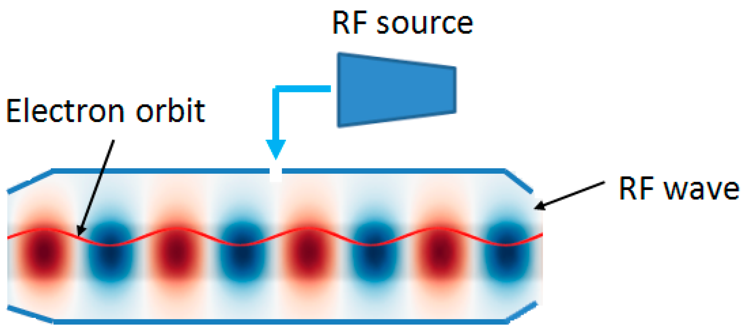
From the electron beam dynamics point of view, it is clear that the usage of magnetic IDs is not the only possible way to provide wiggling (undulating) electron orbits and the idea to replace them with electromagnetic waves (generated by lasers, gyrotrons (and other gyro-devices like Gyro-Klystrons, Gyro-BWO, etc.)) has been conceived a long time ago [14,15,16,17,18,19,20,21]. As an illustration, a schematic of an electromagnetic wiggler/undulator powdered by an RF source is shown in Figure 2. The development of the concepts of gyrotron-driven microwave (aka RF) wigglers [14,15,16,17] and undulators [18,19,20,21] started soon after the gyrotrons demonstrated their potential to provide powerful coherent radiation with wavelengths ranging from centimeters to millimeters. Since these first conceptual design and feasibility studies, the research on this topic continues and is focused on novel advanced concepts [22,23,24,25,26,27,28,29,30] using other radiation sources as well.
In a microwave wiggler/undulator both the transverse electric E and magnetic field H of the electromagnetic wave cause wiggling of the electrons and the K parameter takes the form (in CGS units) [23,30,31]
K w = e ( E + H ) m c 2 ( h + k ) e ( E + H ) λ w   2 π m c 2 e H ( 1 + Z ) λ w   2 π m c 2 ,
where the λ w = 2 π h + k is the undulator period, h = 2 π / λ g is the propagation constant of a wave (with a wavelength λ g ) in the waveguide at angular frequency ω , and k = ω / c is the wavenumber of light in vacuum. The wave impedance Z = E / H for the TE and TM modes is Z T E = k h = Z 0 / 1 ( ω c / ω ) 2 and Z T M = h k = Z 0 1 ( ω c / ω ) 2 , respectively. In these relations Z 0 is the impedance of the free space and ω c is the cut-off frequency of the waveguide/cavity. The wave impedance Z is an important mode-specific parameter that characterizes the used electromagnetic wave. For an operation far from the cut-off ( ω ω c ) it is close to the impedance of the free space.
In more practical units,
K w = 8.5 × 10 15 · λ w [ n m ] I w [ W m 2 ]   ,
where I w is the microwave power density [30]. Thus, for a specified (targeted) value of K w , the required power density I w can be evaluated using (3). For instance, for K w = 1 and λ w = 1 cm, this gives I w = 14 GW/cm2. If the pump wave with an angular frequency ω p and the electron beam propagate towards each other, the frequency of the field oscillation ω “seen” by the electrons will be Doppler shifted
ω = ω p γ ( 1 + v z c ) ,
where γ is the relativistic Lorentz factor and v z is the axial velocity of the electrons. Thus, the radiation frequency in the laboratory system is
ω = ω p γ 2 ( 1 + v z c )   .
Therefore, by controlling the energy of beam electrons the frequency of generated radiation can be easily tuned in a wide frequency band. Since the factor γ 2 can be quite large (recall, for example, that for an electron energy of 511 MeV, γ amounts to 1000) this frequency is much higher than the frequency of the pumping wave.
The emission arising under the action of the pump wave can be regarded as Compton scattering of the pump wave on moving electrons [32]. That is why, sometimes such devices are called FEL-Scattertrons. In the case of a magnetostatic wiggler, the wavelength of the output radiation scales as λ λ w / 2 γ 2 while the wavelength of the output radiation for an electromagnetic-wave wiggler scales as λ λ w / 4 γ 2 . This means that for fixed wiggler periods and beam energies, the electromagnetic-wave wiggler will generate shorter output wavelengths [22]. This makes the electromagnetic-wave wigglers very attractive alternatives to magnetostatic wigglers in the production of short wavelengths when the electron beam energy is constrained.
Before going into detail about their realization it should be mentioned that, generally, the RF IDs provide fast dynamic control of the polarization, wavelength, and the dimensionless K -factor. Distinguishing advantage of the microwave undulators is that they allow much smaller undulator periods ( λ w ~ λ / 2 under the assumption h k ) and larger apertures (cm vs. mm) to be used. The latter circumstance makes it possible to use electron beams with a larger radius and emittance. A critical issue for the conventional undulators with permanent magnets is the potential danger of their demagnetization by radiation. In the case of a microwave undulator, however, such risk is absent.
The microwave undulators, however, require extremely strong RF fields (tens of GW) that cannot be delivered directly even by the most powerful radiation sources. This makes it necessary to use waveguides and cavities in which the needed microwave energy is pumped and accumulated. The required field strength can be sustained by only compensating for the Ohmic losses in the cavity walls. In order to minimize the losses, the cavity dimensions have to be large enough. In such oversized structures, however, the eventual mode conversion losses can also be significant. Another severe problem is the RF breakdown. Both, the former and the latter problem require special structures to be used (e.g., corrugated waveguides [28,33,34]).
Since the microwave wigglers and undulators have many promising and advantageous features in comparison with those utilizing static magnets it is believed that they will be used in the next generations of the FELs [23,25]. The realization of this concept has been delayed due to the absence of powerful enough radiation sources operating at high frequencies and, correspondingly, at short wavelengths of the order of centimeters or several millimeters. The remarkable recent progress demonstrated by the klystrons, magnicon amplifiers, and various gyro-devices (gyro-monotron, cyclotron auto-resonance maser (CARM), etc.) has changed the situation dramatically and has made it possible to propose and develop a range of RF undulators and wigglers. The most notable schemes that utilize gyrotrons or other gyro-devices (e.g., relativistic gyro-klystron [35]) will be discussed in Sect. 3. There we skip, however, the undulators driven by CARM radiation since this topic has been extensively covered by the recent paper [30].

3. Gyrotron-Powered Microwave Wigglers and Undulators

The principles of gyrotron-powered electromagnetic wigglers for FELs have been proposed and discussed in the pioneering paper by B. Danly et al. [14] a long time ago. Analogous concepts have been developed also in [36]. A generic arrangement of an FEL with a gyrotron-driven wiggler/undulator is shown in Figure 3.
On the basis of a theoretical analysis [14], it has been shown that the usage of short wavelength electromagnetic wigglers in waveguides and resonant cavities can significantly reduce the required electron beam accelerating voltages and in such a way would allow building compact FEL’s. The gain calculations have been performed for both the low- and high-gain Compton regime and take into account the effects of emittance, transverse wiggler gradient, and thermal spread of the electron velocities. This paper gives also an insight into the scaling laws for the gain and the required electromagnetic wiggler field power. Moreover, both traveling wave and standing wave resonator fields have been considered as possible electromagnetic wigglers. In the former case, TE1n (n = 2, 3, 4…) modes in a cylindrical waveguide have been examined. They have fields on the axis that can be approximated by plane waves. Such modes are well suited for use as wigglers with high voltage axial electron beams. Moreover, high-power gyrotrons can produce significant power when operating in these modes. Alternatively, an electromagnetic standing wave in a resonator can be used in order to achieve high values of the electromagnetic field by storage of the gyrotron power in a single high-Q cavity mode TE1nl (l being the axial mode index). The resulting standing wave wiggler field can be represented as the sum of two oppositely propagating traveling waves of equal amplitude. This results in two separate FEL resonance conditions corresponding to the two different components of the motion due to the forward and backward waves. Since the low-frequency resonances are undesirable, special design solutions need to be used to prevent oscillations on them.
In the case of a standing wave wiggler, several different design schemes are possible using a conventional gyrotron (with a waveguide cavity) or a quasi-optical gyrotron (with an open-mirror resonator) [14]. Moreover, the power source may be separated from the wiggler cavity, powering the latter through an external coupling. As pointed out in the pioneering paper [14], in this case, “high-power microwave or millimeter wave circulators or isolators would be necessary to prevent reflection of power back to the source. Although these components may be feasible for lower frequency EM wigglers (λ~0.5–1 cm), higher frequency wigglers are likely to require an alternate concept.” So far, this severe problem is not solved for the high-frequency gyrotrons and the only available means is the careful coupling and matching the wave-beam with the RF undulator so that to minimize the reflections. One of the first configurations that have been proposed in [14] is that of an FEL’s operating in the infrared region using moderate energy (<10 MeV electron beams) with electromagnetic wigglers powered by millimeter-wavelength gyrotron. In this scheme, both the gyrotron and the FEL interaction take place in the same closed cavity which, however, has two sections. The gyrotron interaction occurs in the first region where there is the necessary axial magnetic field (needed for its operation) and where the wave number of the excited mode is almost entirely in the transverse direction (i.e., close to cut-off). The radiation produced in the gyrotron section is trapped inside the high-Q cavity and acts as a wiggler for the FEL interaction there. The electron beam accelerated to the required energy enters the cavity through tapered openings (which are cut-off to the trapped mode) or through slots in the resonator walls. Another possibility, discussed in [14], is an electromagnetic wiggler utilizing a traveling wave generated by a gyrotron. In such a scheme the coupling problems are nonexistent but higher peak powers are required than in the case of a high-Q cavity.
FELs with RF standing wave wigglers have been proposed also in [15]. This study includes a detailed analysis of such schemes with both circular and linear wiggler polarizations. The results reported in [15] provide a deep insight into the resonance conditions and the coupling strength associated with each resonance of this type of FEL. A striking feature revealed by this investigation for the first time is that the electromagnetic standing wave wiggler FEL, under certain circumstances, exhibits a rich harmonic content due to the presence of both the forward and backward wave components of the standing wave wiggler field.
Different schemes for infrared FELs based on gyrotron-powered electromagnetic wigglers have been proposed by A. Fliflet et al. in [16,17], where a design of a 10.6 µm electromagnetic wiggler FEL for a proof-of-principle experiment (performed using a 6 MeV electrostatic accelerator with beam currents 2 and 5 A) has been considered. One of the studied wigglers utilizes a waveguide and the other a quasi-optical resonator.
The above-mentioned papers are mainly conceptual design studies and proposals. A convincing example of a successful experimental demonstration of a gyrotron-powered standing-wave electromagnetic wiggler is [37]. The cavity consists of two major sections. The first straight section is the gyrotron interaction region (in other words, the gyrotron cavity) which is tapered down at the electron gun side to the cutoff of the operating mode. On the other side, the cavity is tapered up to another straight section which is referred to as the FEL interaction region or the FEL cavity. To create a standing-wave field in the FEL region, another down-taper is used. The final up-taper provides a gradual transition between the cavity and the output waveguide. The gyrotron has been operated in a regime of high field intensity and short interaction length regime using the mode TE13 at 129.5 GHz. The experimental results indicate that higher wiggler field strengths should be feasible with higher-power electron beams.
Next, we discuss several short-period RF undulators. The first one is a traveling wave undulator for the SASE (self-amplified spontaneous emission) source [35] made of a low-loss resonant ring where an operating wave moves toward the electron beam in one of ring’s arms. As possible radiation sources, a magnicon and a relativistic gyro-klystron have been considered. This 34 GHz room-temperature RF undulator exploits the superposition of the hybrid HE11 and HE12 modes in a corrugated waveguide to minimize the losses. The authors estimate that in order to obtain parameter K w = 0.4 in the waveguide of L = 250 mm length, about 120 MW input power, 470 ns filling time (loaded Q-factor 5.1× 10⁴ at waveguide radius 26.5 mm) are necessary. It has been concluded that among the considered schemes the hybrid HE11 mode resonant ring is distinguished by the simplest design, and low surface fields, but the feeding requires huge RF power. On the other side, the TE01/TE02 resonator with short efficient mode converters and coaxial coupler requires moderate power, has low surface fields, and can be operated in a regime of long pulses albeit the heating temperature is rather high. Another proposed undulator uses near to cut-off TM11 mode which has frequency up-shift two times less in comparison with other considered versions but provides many advantages. Among them are low input power, low surface fields, simple design, and the possibility to be operated in a regime of long bunches. Several promising configurations for RF undulators powered at millimeter wavelengths and designed to produce coherent nanometer radiation from sub-GeV electron beams are analyzed and compared with one another in [23]. These schemes include a traveling-wave resonant ring, a standing wave resonator, and a resonator operating close to the cutoff.
One of the most advanced recently proposed concepts is the so-called “flying undulator”, which represents a short microwave pulse that synchronously propagates with the driving electron bunch and provides pumping of its oscillations. Profiling the parameters of a “flying” undulator [26] allows the realization of the non-resonant trapping regime resulting in further enhancement of the FEL efficiency. Recently, such undulators designed for the K and W bands have been studied both numerically and experimentally (“cold tests”) [38].
Waveguide-type microwave undulator based on a helically corrugated waveguide that supports a traveling wave has been studied in [28,33]. The use of such an approach allows partial conversion of a traveling wave mode into a backward traveling wave mode, thus increasing the effective interaction length. When operating with a TE11 mode at 30.3 GHz, the undulator is predicted to realize field strength of ~0.3 T and an undulator period of 4.95 mm when driven by 1 GW of microwave power. The authors of [28] have selected the TE11 mode as the operating one because it has a strong equivalent transverse magnetic field in the waveguide axis, as well as a large flat field region in the waveguide center, although it has the disadvantage of large Ohmic losses. Other possible operating modes have also been considered. One of them is the TE01 which has the lowest Ohmic losses.
As already mentioned, the enormous power required by the RF undulators makes it necessary to use resonant cavities for the accumulation of microwave energy or pulse compression power amplification [33]. The filling of the cavity stored energy W ( t ) at time t   is given by Slatter’s formula [39,40] (with a few changes in the notations)
W ( t ) = P 0 τ 0 4 q ( 1 + q ) 2 [ 1 exp ( 1 + q 2 t τ 0 ) ] 2   ,
where P 0 is the input power produced by an microwave source (e.g., gyrotron) and coupled to the resonator with an intrinsic (Ohmic) quality factor Q 0 (at frequency ω ) by an input port. Here, τ 0 = Q 0 / ω , q = Q 0 / Q e and Q e is the external Q-factor. The quantity q is therefore the coupling factor for the cavity and the input port since it is related to the fractions of the input powers that are transmitted and reflected. In a steady-state (when τ o ) the stored energy reaches the maximum value of P 0 τ 0 if q = 1 (i.e., if the cavity is properly coupled). In this case, the input power fully compensates the Ohmic losses. As evident from (6), in the cases of under-coupled ( q < 1 ) and over-coupled ( q > 1 ) cavity the stored energy is smaller. The filling time of the cavity is [33]
t t r = Q 0 ω 2 1 + q ln ( 1 + χ 1 / 2 1 χ )   ,
where χ is the charging factor defined as the ratio of the charged energy and its maximum value. From the above equations, it follows that cavities with high Q factors are more preferable in order to achieve maximum storage at given input power although the filling time also increases.
Although in this section we were focused on the gyrotron-powered undulators it should be mentioned that their alternatives (and competitors) that are based on lasers are considered very promising. Among them are the recirculated wave undulators for compact FEL [41,42]. The system employs a recirculated radiation pulse serving as an undulator provided by a high-power laser. The scheme uses an optical ring cavity composed of two plane mirrors, two parabolic mirrors, and one focusing lens. It has been estimated that a CO2 laser with an intensity of 4.2 × 10¹⁸ W/m2 corresponding to an energy of 40 J per pulse delivered in 300 ps over an effective area~ π 10 8 m2 would be enough to provide a wave undulator with sufficiently large to support the FEL SASE operation.
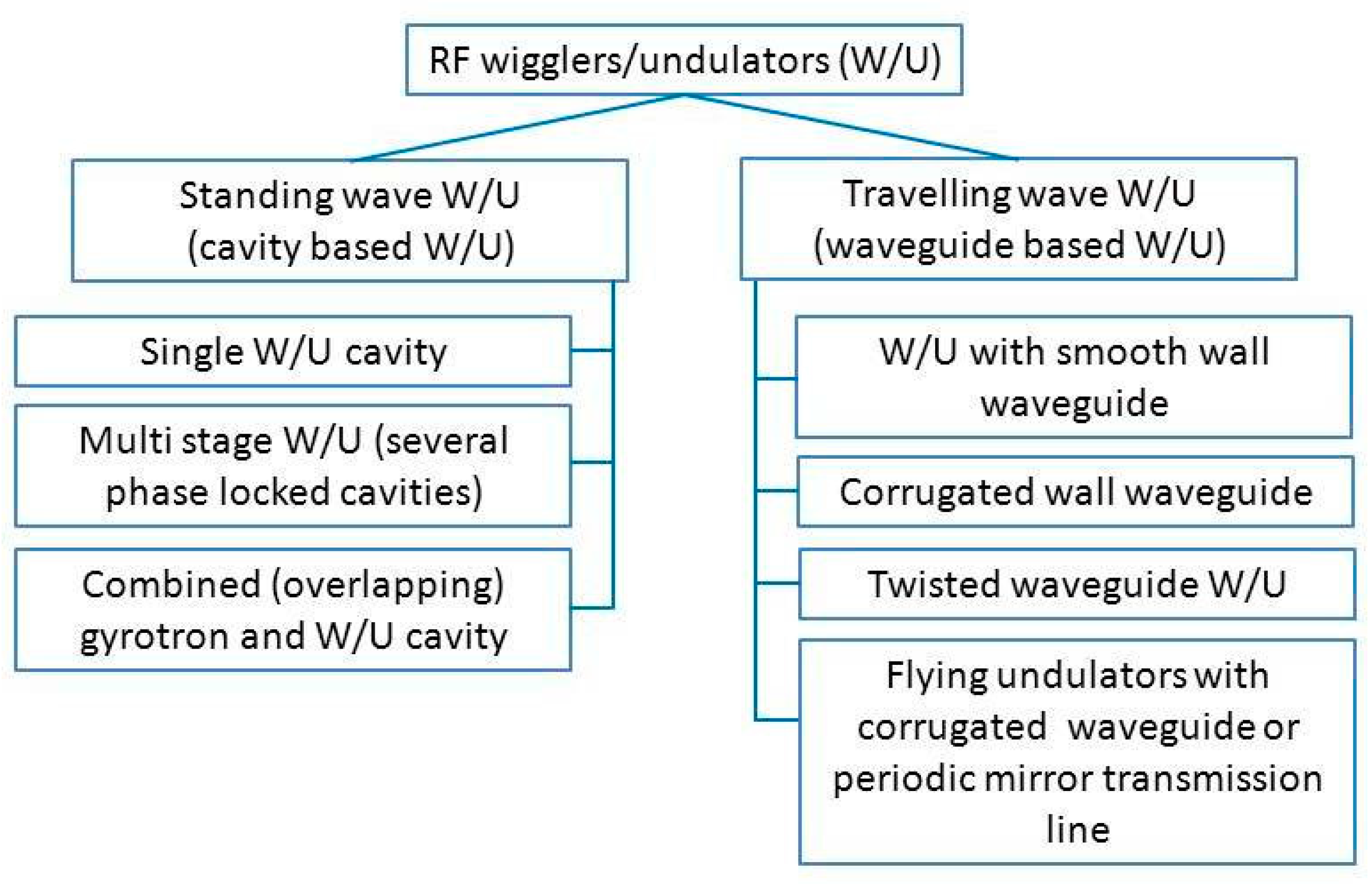
Some of the envisaged schemes of gyrotron-driven wigglers/undulators and presented in this section are classified in Figure 4.

4. Gyrotron-Driven Ultra-Compact Particle Accelerators

Accelerators of charged particles are powerful tools in fundamental research (e.g., nuclear and high-energy physics), medicine, material treatment, security, and many other advanced technologies. They, however, are bulky and large (of the order of several meters or even tens of meters) expensive, and require sophisticated infrastructure. All these characteristics make it difficult to embed them in both the laboratory and industrial environments, where they are used. The progress in the development of the high-power RF sources allows transition to higher frequencies and peak field amplitudes which results in more compact accelerating structures. Generally, there are two ways to miniaturization namely traveling wave and standing wave structures. Besides the traditional RF sources (e.g., klystrons) [43,44], it has been proposed a long time ago to use gyrotron-driven accelerating cavities [45,46,47,48] including such based on gyro-klystrons [48,49,50,51]. Their important advantages are: (1) high accelerating gradients up to above 200 MV/m; (2) mm-size dimensions of the structure produce more efficient RF cavities; (3) increased frequency results in significantly shorter fill times, thus the energy needed to power the accelerator decreases dramatically, enabling higher repetition rates; (4) the gyrotron radiation can be transported, switched and compressed with quasi-optical elements.
The role of frequency increase is clear from the following scaling relations (derived for typical disk-loaded traveling wave structures) [43]
P [ MW m ] 6.6 × 10 2 E a 2 [ MV m ] υ 1 2 [ GHz ]   ,
t f [ ns ] 3.8 × 10 3 υ 3 2 [ GHz ]     ,
u [ J m ] P t f 0.25 E a 2 [ MV m ] ν 2 [ GHz ] .
Here P is the microwave power per unit length that is required to achieve a gradient E a with RF power of frequency   ν , t f is the fill time of the accelerating structure, and u is the necessary microwave energy per unit length. From these scaling relations, it is obvious that for a particular design that is characterized by a gradient E a less RF average power is required at higher frequencies.
To illustrate the current progress in the development of gyro-klystrons for high-gradient accelerators two examples will be given. The 36 GHz RF system presented in [51] utilizes a 30 cm long slow-wave structure (SWS) and delivers more than 12 MV of linearising voltage at a 1 kHz repetition rate, and operating at a gradient of 42.5 MV/m. The developed RF sources are capable of delivering up to 3 MW, 1 μs pulses at a 1 kHz repetition rate using moderate modulator voltages. The second example is the MW-level 48 GHz gyro-klystron amplifier [52]. The design of the gyro-klystron is expected to deliver an output power of up to 2.3 MW with a gain of 36 dB and an efficiency of 44% at 48 GHz, when driven by an electron beam of voltage 140 kV and current 37 A.
The remarkable history of the University of Maryland’s program that has been focused on the investigations of gyro-amplifiers as potential sources for linear colliders is presented in detail in the review paper [53] which includes essential references to the early work on this topic.
It has been estimated that using one megawatt of RF power from the gyrotron may allow reaching a peak accelerating gradient of 400 MeV/m [54,55,56]. In order to test the developed mm-wave standing-wave single-cell accelerating structure, a pulsed gyrotron operating at 110 GHz has been used.
RF breakdown (both direct and multipactoring) is one of the major phenomena that limit the achievable gradient in accelerating structures. The probability of RF breakdown in a single-cell standing wave accelerator cavity powered by a 110 GHz gyrotron has been carried out in [57]. It has been reported that the pursued high-frequency accelerator concept is characterized by a high degree of tunability in both power and pulse width. Pulse widths from <3 ns to 3 μs have been generated at continuously-variable power levels up to 650 kW. The accelerator structure tested at STARRE Lab has already demonstrated accelerating gradients of greater than 220 MV/m.
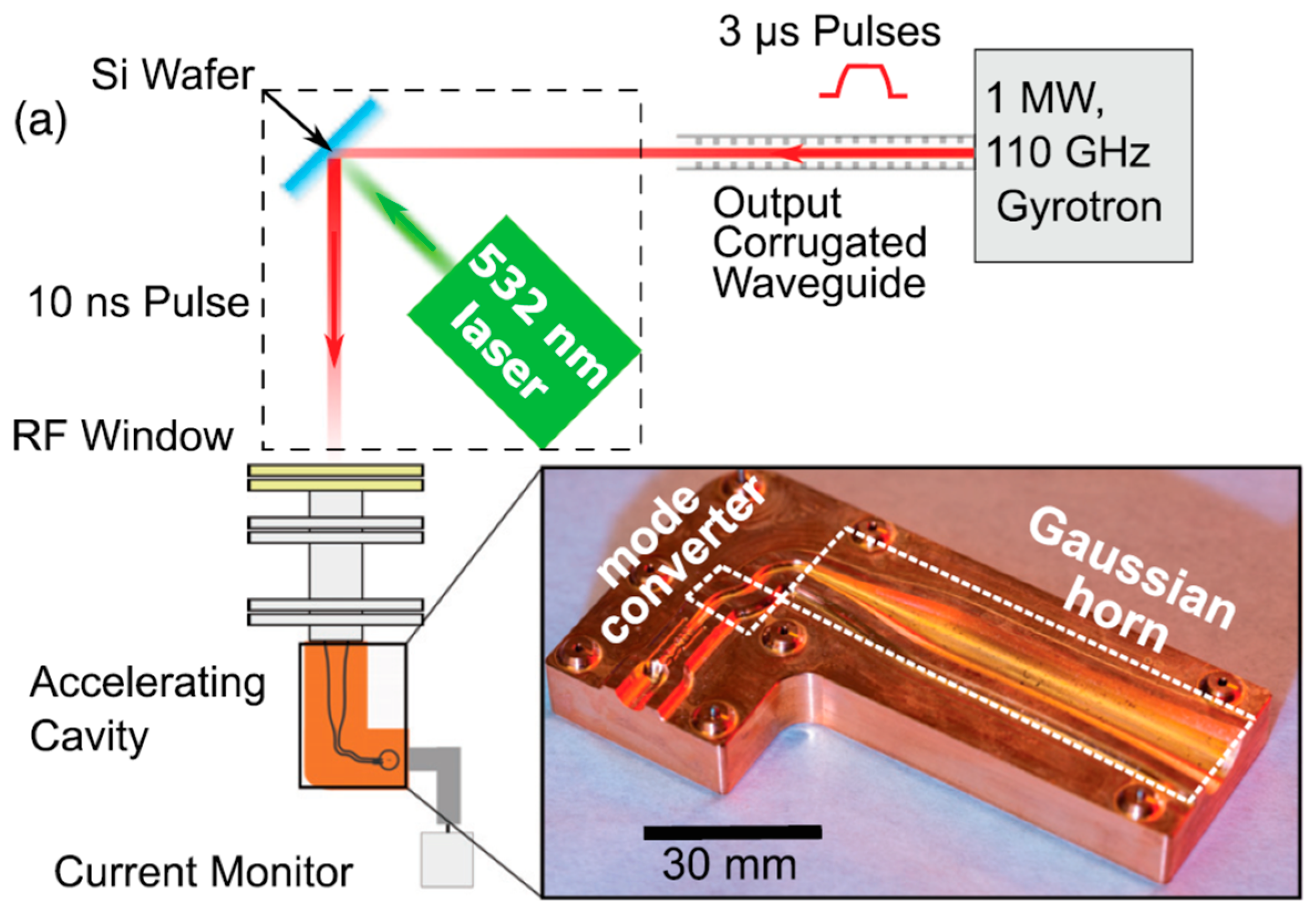
The above-mentioned advanced accelerator concept at sub-THz frequencies utilizes a laser-driven semiconductor switch (LDSS) to modulate the output of a megawatt-class gyrotron (which generates 3 μs pulses with a repetition frequency of up to 6 Hz) and to produce megawatt-level, nanosecond-duration, sub-THz pulses [58,59,60,61]. This concept is illustrated in Figure 5. Such a setup reflects the gyrotron radiation by inducing temporary reflectance in a semiconductor wafer generating there an electron-hole plasma. The LDSS are employing silicon (Si) or gallium arsenide (GaAs) wafers. For both semiconductor materials, a higher value of reflectance was observed with increasing 110-GHz beam intensity [58]. Furthermore, using two active wafers, pulses of variable length down to 3 ns duration have been produced.
Recently, following the same approach and using a quasi-optical setup, reliable coupling of an unprecedented RF power (up to 575 kW) to the mm-wave accelerating structure has been demonstrated [59,60,61]. Figure 6 shows the standing wave accelerating structure which consists of a single-cell copper cavity and a Gaussian to TE11 to TM01 mode converter. The accelerator structure is powered by 110 GHz, 10-ns long RF pulses. The latter are chopped from 3 µs pulses from a gyrotron oscillator using an LDSS (as already described in [58]). In this study, an unprecedented high gradient up to 230 MV/m that corresponds to a peak surface electric field of more than 520 MV/m has been achieved. The LDSS is a Si wafer illuminated by an intense Nd:YAG laser with a wavelength of 523 nm that produces 6 ns pulse with an energy of 230 mJ. The RF breakdown rates (BDRs) in this millimeter-wave accelerating cavity powered by a megawatt gyrotron have been measured in [60]. The observed BDR in the last 103 shots (after being previously conditioned by 105 shots) at a gradient of 230 MV/m is about 10−3 [1/pulse].
The relativistic gyrotrons developed at IAP-RAS [62,63] have a great potential for feeding the new generation of linear electron accelerators. These radiation sources operate with electron beams with energies of 250–300 keV at a wavelength of 10 mm with an efficiency of 50% [62] and at a wavelength of 3 mm with an efficiency of around 20% [63]. The possibility of reaching an output power of 200–250 MW by a relativistic gyrotron at a wavelength of 10 mm has been demonstrated by numerical simulations [64]. Such a powerful radiation source could be used for driving RF undulators and accelerating structures.
Another advanced concept is to use a dielectric-loaded room-temperature accelerating structure of standing-wave type. Extremely high-quality factor and high shunt impedance can be realized utilizing ultralow-loss (tanδ = 10−5–10−6) dielectrics (diamond, TiO2- doped Al2O3 ceramics) [65]. The structure is composed of stacking dielectric discs with a diameter of ~4 mm. In each of them, the Bragg ring grooves and the channels of electrons with a diameter of 0.3 mm are ablated by using a femtosecond laser. The first variety is a 300 GHz CW millimeter-wave diamond structure. It is appropriate for 1 MeV range CW linear accelerators used for food irradiation, sterilization, industrial radiography, and cargo inspection. To obtain 1 MeV acceleration in a 10 cm long structure with an accelerating field of 10 MV/m a gyrotron with CW power of 3 kW is considered. The second variety is a C-band CW structure made of TiO2- doped Al2O3 ceramic. According to the computer-aided design, the 1 MeV dielectric-loaded accelerator with a 1 MV/m accelerating gradient has only 1.53 kW thermal losses (of which 46% is the dielectric loss).
In the framework of the Ultra-Compact XFEL project which is being pursued at the University of California, Los Angeles [66], a high-gradient 34 GHz standing-wave RF accelerating structure for the longitudinal phase-space linearization with an integrated voltage of at least 15 MV working on the 6th harmonic of the main Linac frequency has been investigated recently. Based on analytical and numerical studies of the possible designs, an in-depth analysis of the requirements imposed on the different components has been presented. Additionally, it is reported that estimations on the gyro-klystrons provide an RF output of about 3 MW that, in combination with the pulse compressor system, can generate an RF output power of 12 MW in order to feed the Ka-band linearizer.

5. Conclusions and Outlook

The remarkable recent progress in the development of high-performance gyrotrons with output characteristics that are appropriate for both microwave wigglers/undulators and high-gradient accelerating structures in compact particle accelerators. Although the specific requirements for each of these two applications are different, they have much in common and can easily be satisfied using a unified approach based on the available adequate self-consistent physical models and numerical codes for computer-aided design (CAD). While currently in most of the studies and experiments the utilized gyrotrons have been initially developed for heating of fusion plasmas, we anticipate the development of dedicated (specialized) tubes for gyrotron-based microwave undulators for FEL and high-gradient accelerators.
Another important factor that will facilitate the further development of these systems is the availability of auxiliary means for the manipulation of high-power microwaves. They include advanced RF technologies for transmission (e.g., using low-loss corrugated waveguides, oversized high-power waveguide components [67], and quasi-optical lines), mode converters, steerable reflectors, pulse compressors, LDSS, etc. All this means that nowadays not only powerful gyrotrons are at hand but also the rest of the necessary components for handling their radiation already exist. It is believed that such synergy will accelerate further the development of gyrotron-powered microwave wigglers/undulators and compact accelerating structures.
There is at least one more application of the gyrotrons related to the charged particle accelerators, namely in the Electron Cyclotron Resonance Ion Sources (ECRIS). The current (4th generation) of ECRIS utilizing gyrotrons can provide highly-charged ions for ion accelerators (see, e.g., [68]). This topic, however, is outside of the scope of this paper and will be discussed elsewhere.

Author Contributions

The authors contributed equally to the preparation of this review article. All authors have read and agreed to the published version of the manuscript.

Funding

This research received no external funding.

Informed Consent Statement

Not applicable.

Data Availability Statement

Not applicable.

Conflicts of Interest

The authors declare no conflict of interest.

References

  1. Thumm, M. State-of-the-Art of High-Power Gyro-Devices and Free Electron Masers. J. Infrared Millim. Terahertz Waves 2020, 41, 1–140. [Google Scholar] [CrossRef] [Green Version]
  2. Benford, J.; Swegle, J.A.; Schamiloglu, E. High Power Microwaves, 2nd ed.; CRC Press: Boca Raton, FL, USA, 2007; ISBN 9780429141409. [Google Scholar] [CrossRef]
  3. Idehara, T.; Saito, T.; Ogawa, I.; Mitsudo, S.; Tatematsu, Y.; Sabchevski, S. The potential of the gyrotrons for development of the sub-terahertz and the terahertz frequency range—A review of novel and prospective applications. Thin Solid Film. 2008, 517, 1503–1506. [Google Scholar] [CrossRef]
  4. Thumm, M.; Denisov, G.; Sakamoto, K.; Tran, M. High-power gyrotrons for electron cyclotron heating and current drive. Nucl. Fusion 2019, 59, 073001. [Google Scholar] [CrossRef]
  5. Idehara, T.; Sabchevski, S.P.; Glyavin, M.; Mitsudo, S. The Gyrotrons as Promising Radiation Sources for THz Sensing and Imaging. Appl. Sci. 2020, 10, 980. [Google Scholar] [CrossRef] [Green Version]
  6. Kumar, N.; Singh, U.; Singh, T.P.; Sinha, A.K. A Review on the Applications of High Power, High Frequency Microwave Source: Gyrotron. J. Fusion Energy 2011, 30, 257–276. [Google Scholar] [CrossRef]
  7. Temkin, R.J. Development of terahertz gyrotrons for spectroscopy at MIT. Terahertz Sci. Technol. 2014, 7, 1–9. [Google Scholar] [CrossRef]
  8. Glyavin, M.; Sabchevski, S.; Idehara, T.; Mitsudo, S. Gyrotron-Based Technological Systems for Material Processing—Current Status and Prospects. J. Infrared Millim. Terahertz Waves 2020, 41, 1022–1037. [Google Scholar] [CrossRef]
  9. Sabchevski, S.; Glyavin, M.; Mitsudo, S.; Tatematsu, Y.; Idehara, T. Novel and Emerging Applications of the Gyrotrons Worldwide: Current Status and Prospects. J. Infrared Millim. Terahertz Waves 2021, 42, 715–741. [Google Scholar] [CrossRef]
  10. Clarke, J.A. The Science and Technology of Undulators and Wigglers; Oxford Series on Synchrotron Radiation; Oxford University Press: Oxford, UK, 2004; ISBN 9780198508557. [Google Scholar]
  11. Onuki, H.; Elleaume, P. (Eds.) Undulators, Wigglers and Their Applications; Taylor & Francis: Abingdon, UK, 2003; ISBN 0-415-28040-0. [Google Scholar]
  12. Ciocci, F.; Dattoli, G.; Torre, A.; Renieri, A. Insertion Devices for Synchrotron Radiation and Free Electron Laser; World Scientific: Singapore, 2000. [Google Scholar]
  13. Winick, H.; Brown, G.; Halbach, K.; Harris, J. Wiggler and undulator magnets. Phys. Today 1981, 34, 50–63. [Google Scholar] [CrossRef]
  14. Danly, B.; Davidson, R.; Temkin, R.; Wurtele, J.; Bekefi, G.; Tran, T. Principles of gyrotron powered electromagnetic wigglers for free-electron lasers. IEEE J. Quantum Electron. 1987, 23, 103–116. [Google Scholar] [CrossRef]
  15. Tran, T.; Danly, B.; Wurtele, J. Free-electron lasers with electromagnetic standing wave wigglers. IEEE J. Quantum Electron. 1987, 23, 1578–1589. [Google Scholar] [CrossRef] [Green Version]
  16. Fliflet, A.; Manheimer, W.M.; Fischer, R.P. Designs for an infrared free-electron laser based on gyrotron-powered electromagnetic wigglers. IEEE Trans. Plasma Sci. 1994, 22, 638–648. [Google Scholar] [CrossRef]
  17. Fliflet, A.; Manheimer, W.; Sprangle, P. Low-voltage infrared free-electron lasers based on gyrotron-powered RF wigglers. IEEE J. Quantum Electron. 1997, 33, 669–676. [Google Scholar] [CrossRef] [Green Version]
  18. Shintake, T.; Huke, K.; Tanaka, J.; Sato, I.; Kumabe, I. Microwave Undulator. Jpn. J. Appl. Phys. 1982, 21, L601–L603. [Google Scholar] [CrossRef]
  19. Shintake, T.; Huke, K.; Tanaka, J.; Sato, I.; Kumabe, I. Development of Microwave Undulator. Jpn. J. Appl. Phys. 1983, 22, 844–851. [Google Scholar] [CrossRef]
  20. Gea-Banacloche, J.; Moore, G.; Schlicher, R.; Scully, M.; Walther, H. Proposal for a compact FEL with electromagnetic-wave undulator. Nucl. Instrum. Methods Phys. Res. Sect. A Accel. Spectrometers Detect. Assoc. Equip. 1988, 272, 199–205. [Google Scholar] [CrossRef]
  21. Kang, Y.; Song, J.; Kustom, R. A Microwave Beam Waveguide Undulator for a Brilliant above 100 keV Photon Source. In Proceedings of the 1999 Particle Accelerator Conference (Cat. No. 99CH36366), New York, NY, USA, 27 March–2 April 1999; Volume 1, pp. 168–170. [Google Scholar] [CrossRef] [Green Version]
  22. Kuzikov, S.V.; Hirshfield, J.L.; Jiang, Y.; Marshall, T.C.; Vikharev, A.A. RF Undulator for Compact X-ray SASE Source of Variable Wavelength. AIP Conf. Proc. 2012, 1507, 458–463. [Google Scholar] [CrossRef]
  23. Kuzikov, S.V.; Jiang, Y.; Marshall, T.C.; Sotnikov, G.V.; Hirshfield, J.L. Configurations for short period rf undulators. Phys. Rev. Spéc. Top.-Accel. Beams 2013, 16, 070701. [Google Scholar] [CrossRef] [Green Version]
  24. Tantawi, S.; Shumail, M.; Neilson, J.; Bowden, G.; Chang, C.; Hemsing, E.; Dunning, M. Experimental Demonstration of a Tunable Microwave Undulator. Phys. Rev. Lett. 2014, 112, 164802. [Google Scholar] [CrossRef]
  25. Abubakirov, E.B.; Bandurkin, I.V.; Vikharev, A.; Kuzikov, S.V.; Rozental, R.; Savilov, A.V.; Fedotov, A.E. Microwave Undulators and Electron Generators for New-Generation Free-Electron Lasers. Radiophys. Quantum Electron. 2016, 58, 755–768. [Google Scholar] [CrossRef]
  26. Kuzikov, S.V.; Savilov, A.V.; Vikharev, A.A. Flying radio frequency undulator. Appl. Phys. Lett. 2014, 105, 033504. [Google Scholar] [CrossRef]
  27. Freund, H.P.; Antonsen, T.M. Electromagnetic-Wave Wigglers. In Principles of Free Electron Lasers; Springer: Cham, Switzerland, 2018. [Google Scholar] [CrossRef]
  28. Zhang, L.; He, W.; Clarke, J.; Ronald, K.; Phelps, A.D.R.; Cross, A.W. Microwave Undulator Using a Helically Corrugated Waveguide. IEEE Trans. Electron Devices 2018, 65, 5499–5504. [Google Scholar] [CrossRef] [Green Version]
  29. Toufexis, F.; Tantawi, S.G. Development of a millimeter-period rf undulator. Phys. Rev. Accel. Beams 2019, 22, 120701. [Google Scholar] [CrossRef] [Green Version]
  30. Di Palma, E.; Ceccuzzi, S.; Ravera, G.L.; Sabia, E.; Spassovsky, I.; Dattoli, G. Radio-Frequency Undulators, Cyclotron Auto Resonance Maser and Free Electron Lasers. Appl. Sci. 2021, 11, 9499. [Google Scholar] [CrossRef]
  31. Dattoli, G.; Renieri, A.; Torre, A. Lectures on Free Electron Laser Theory and on Related Topics; World Scientific: Singapore, 1993. [Google Scholar]
  32. Bratman, V.L.; Denisov, G.G.; Ginzburg, N.S.; Smorgonsky, A.V.; Korovin, S.D.; Polevin, S.D.; Rostov, V.V.; Yalandin, M.I. Stimulated scattering of waves in microwave generators with high-current relativistic electron beams: Simulation of two-stage free-electron lasers. Int. J. Electron. 1985, 59, 247–289. [Google Scholar] [CrossRef]
  33. Zhang, L.; He, W.; Clarke, J.; Ronald, K.; Phelps, A.D.R.; Cross, A. Systematic study of a corrugated waveguide as a microwave undulator. J. Synchrotron Radiat. 2019, 26, 11–17. [Google Scholar] [CrossRef] [Green Version]
  34. Yeddulla, M.; Geng, H.; Ma, Z.; Huang, Z.; Tantawi, S. Waveguide Structures for RF Undulators with Applications to FELs and Storage Rings. In Proceedings of the EPAC08, Genoa, Italy, 23–27 June 2008. SLAC-PUB-14670. [Google Scholar]
  35. Kuzikov, S.V.; Vikharev, A.A.; Plotkin, M.E.; Hirshfield, J.L.; Marshall, T.C.; Sotnikov, G.V.; Peskov, A.V. A short-period RF undulator for a nanometer SASE source. In Proceedings of the IPAC 2011-2nd International Particle Accelerator Conference, San Sebastian, Spain, 4–9 September 2011; pp. 3293–3295. [Google Scholar] [CrossRef] [Green Version]
  36. Ciocci, F.; Dattoli, G.; Walsh, J. A short note on the wave-undulator FEL operation. Nucl. Instrum. Methods Phys. Res. Sect. A Accel. Spectrometers Detect. Assoc. Equip. 1985, 237, 401–403. [Google Scholar] [CrossRef]
  37. Chu, T.; Danly, B.; Temkin, R. A gyrotron-powered standing-wave electromagnetic wiggler experiment. Nucl. Instrum. Methods Phys. Res. Sect. A Accel. Spectrometers Detect. Assoc. Equip. 1989, 285, 246–252. [Google Scholar] [CrossRef] [Green Version]
  38. Vikharev, A.; Kuzikov, S.V.; Peskov, N.Y.; Proyavin, M.D.; Savilov, A.V. Development of “Flying” RF-Undulators with Regular and Profiled Parameters for FELs of Compton-Type. In Proceedings of the 2021 46th International Conference on Infrared, Millimeter and Terahertz Waves (IRMMW-THz), Chengdu, China, 29 August–3 September 2021; pp. 1–2. [Google Scholar] [CrossRef]
  39. Slater, J.C. Microwave Electronics; Van Nostrand: New York, NY, USA, 1950. [Google Scholar]
  40. Alvarez, R.A. Some properties of microwave resonant cavities relevant to pulse-compression power amplification. Rev. Sci. Instrum. 1986, 57, 2481–2488. [Google Scholar] [CrossRef]
  41. Curcio, A.; Dattoli, G.; Ferrario, M.; Giulietti, D.; Nguyen, F. An optical cavity design for a compact wave-undulator based-FEL. Opt. Commun. 2017, 405, 197–200. [Google Scholar] [CrossRef]
  42. Curcio, A. Recirculated Wave Undulators for Compact FELs. Appl. Sci. 2021, 11, 5936. [Google Scholar] [CrossRef]
  43. Danly, B.G. RF sources for linear colliders. AIP Conf. Proc. 1995, 335, 25–38. [Google Scholar] [CrossRef] [Green Version]
  44. Gold, S.H.; Nusinovich, G. Review of high-power microwave source research. Rev. Sci. Instrum. 1997, 68, 3945–3974. [Google Scholar] [CrossRef]
  45. Prosnitz, D. Millimeter High Power Sources for High Gradient Accelerators. IEEE Trans. Nucl. Sci. 1983, 30, 2754–2757. [Google Scholar] [CrossRef]
  46. Neilson, J. A High peak power, X-band gyroklystron for linear accelerators. In Proceedings of the 1986 International Linac Conference, Stanford, CA, USA, 2–6 June 1986; pp. 166–168, No. SLAC—303. [Google Scholar]
  47. Tran, M.Q. High Power Gyrotrons as Microwave Sources for Panicle Accelerators. In Proceedings of the EPS Workshop on New Developments in Particle Acceleration Techniques, ECFA 87/I 10, Orsay, France, 29 June–4 July 1987; pp. 223–230. [Google Scholar] [CrossRef]
  48. Granatstein, V.L.; Lawson, W. Gyro-amplifiers as candidate RF drivers for TeV linear colliders. IEEE Trans. Plasma Sci. 1996, 24, 648–665. [Google Scholar] [CrossRef]
  49. Lawson, W.; Granatstein, V.L.; Hogan, B.; Koc, U.V.; Latham, P.E.; Main, W.; Matthews, H.W.; Nusinovich, G.S.; Reiser, M.; Striffler, C.D.; et al. Experimental gyroklystron research at the University of Maryland for application to TeV linear colliders. AIP Conf. Proc. 1992, 279, 26–41. [Google Scholar]
  50. Lawson, W.; Ives, R.; Mizuhara, M.; Neilson, J.; Read, M.E. Design of a 10-MW, 91.4-GHz frequency-doubling gyroklystron for advanced accelerator applications. IEEE Trans. Plasma Sci. 2001, 29, 545–558. [Google Scholar] [CrossRef]
  51. Castilla, A.; Zhang, L.; Wu, X.; Wuensch, W.; Spataro, B.; Latina, A.; Cross, A.W.; Burt, G.; Syratchev, I.; Behtouei, M.; et al. Development of 36 GHz RF systems for RF linearisers. In Proceedings of the 12th International Particle Accelerator Conference, Campinas, Brazil, 24–28 May 2021; BRA. JACoW Publishing: Geneva, Switzerland, 2021; pp. 4518–4523, ISBN 9783954502141. [Google Scholar]
  52. Nix, L.J.R.; Zhang, L.; He, W.; Donaldson, C.R.; Ronald, K.; Cross, A.W.; Whyte, C.G. Demonstration of efficient beam-wave interaction for a MW-level 48 GHz gyroklystron amplifier. Phys. Plasmas 2020, 27, 053101. [Google Scholar] [CrossRef]
  53. Lawson, W.; Calame, J.P.; Nusinovich, G.S.; Hogan, B. Reflections on the university of Maryland’s program investigating gyro-amplifiers as potential sources for linear colliders. THz Sci. Technol. 2017, 10, 1–43. [Google Scholar] [CrossRef]
  54. Nanni, E.A.; Dolgashev, V.A.; Haase, A.A.; Neilson, J. Toward high-power high-gradient testing of mm-wave standing-wave accelerating structures. In Proceedings of the 9th International Particle Accelerator Conference IPAC2018, Vancouver, BC, Canada, 29 April–4 May 2018; JACoW Publishing: Geneva, Switzerland, 2018. ISBN 978-3-95450-184-7. [Google Scholar] [CrossRef]
  55. Nanni, E.A.; Dal Forno, M.; Dolgashev, V.; Neilson, J.; Schaub, S.; Tantawi, S.; Temkin, R. Mm-wave standing-wave accelerating structures for high-gradient tests. In Proceedings of the 7th International Particle Accelerator Conference (IPAC’16), Busan, Korea, 8–13 May 2016; pp. 8–13, ISBN 978-3-95450-147-2. [Google Scholar]
  56. Nanni, E.A.; Dolgashev, V.; Jawla, S.; Neilson, J.; Othman, M.; Picard, J.; Schaub, S.; Spataro, B.; Tantawi, S.; Temkin, R.J. Results from mm-Wave Accelerating Structure High-Gradient Tests. In Proceedings of the 2018 43rd International Conference on Infrared, Millimeter, and Terahertz Waves (IRMMW-THz), Nagoya, Japan, 9–14 September 2018; pp. 1–2. [Google Scholar] [CrossRef]
  57. Picard, J.F.; Schaub, S.C.; Temkin, R.J. STARRE LAB: The sub-THZ Accelerator Research Laboratory. In Proceedings of the North American Particle Accelerator Conference, NAPAC2019, Lansing, MI, USA, 2–6 September 2019; ACoW Publishing: Geneva, Switzerland, 2019. ISBN 978-3-95450-223-3. [Google Scholar] [CrossRef]
  58. Picard, J.F.; Schaub, S.C.; Rosenzweig, G.; Stephens, J.C.; Shapiro, M.A.; Temkin, R.J. Laser-driven semiconductor switch for generating nanosecond pulses from a megawatt gyrotron. Appl. Phys. Lett. 2019, 114, 164102. [Google Scholar] [CrossRef]
  59. Othman, M.A.K.; Picard, J.; Schaub, S.; Dolgashev, V.A.; Lewis, S.M.; Neilson, J.; Haase, A.; Jawla, S.; Spataro, B.; Temkin, R.J.; et al. Experimental demonstration of externally driven millimeter-wave particle accelerator structure. Appl. Phys. Lett. 2020, 117, 073502. [Google Scholar] [CrossRef]
  60. Kutsaev, S.; Jacobson, B.; Smirnov, A.; Campese, T.; Dolgashev, V.; Goncharik, V.; Harrison, M.; Murokh, A.; Nanni, E.; Picard, J.; et al. Nanosecond rf-Power Switch for Gyrotron-Driven Millimeter-Wave Accelerators. Phys. Rev. Appl. 2019, 11, 034052. [Google Scholar] [CrossRef] [Green Version]
  61. Othman, M.A.; Picard, J.; Schaub, S.; Dolgashev, V.A.; Lewis, S. High Gradient and rf Breakdown Measurements in a Millimeter-Wave Accelerating Cavity. In Proceedings of the 2020 45th International Conference on Infrared, Millimeter, and Terahertz Waves (IRMMW-THz), Buffalo, NY, USA, 8–13 November 2020; pp. 1–2. [Google Scholar] [CrossRef]
  62. Zaitsev, N.I.; Zavolsky, N.A.; Zapevalov, V.E.; Ilyakov, E.V.; Kulagin, I.S.; Lygin, V.K.; Moiseev, M.A.; Nechaev, V.E.; Petelin, M.I.; Rozental, R. Ten-Megawatt Pulsed Gyrotron with a 1-cm Wavelength and a 50% Efficiency. Radiophys. Quantum Electron. 2003, 46, 816–819. [Google Scholar] [CrossRef]
  63. Abubakirov, E.B.; Chirkov, A.V.; Denisov, G.G.; Guznov, Y.; Kornishin, S.Y.; Leontyev, A.N.; Plankin, O.P.; Rozental, R.; Sedov, A.S.; Semenov, E.; et al. W-Band 5 MW Pulse Relativistic Gyrotron. IEEE Trans. Electron Devices 2017, 64, 1–3. [Google Scholar] [CrossRef]
  64. Abubakirov, B.; Denisenko, A.N.; Konyushkov, A.P.; Osharin, I.; Rozental, R.M.; Tarakanov, V.P.; Fedotov, A. Developing a high-current relativistic millimeter-wave gyrotron. Bull. Russ. Acad. Sci. Phys. 2018, 82, 48–52. [Google Scholar] [CrossRef]
  65. Antipov, S.; Avrakhov, P.; Gomez, E.; Kuzikov, S.; Vikharev, A. CW Room Temperature Accelerating Structures. In Proceedings of the 10th International Particle Accelerator Conference (IPAC’19), Melbourne, Australia, 19–24 May 2019; JACOW Publishing: Geneva, Switzerland; pp. 2990–2992. [Google Scholar] [CrossRef]
  66. Spataro, B.; Behtouei, M.; Faillace, L.; Variola, A.; Dolgashev, V.; Rosenzweig, J.; Torrisi, G.; Migliorati, M. Ka-band linearizer for the Ultra-Compact X-ray free-electron laser at UCLA. Nucl. Instrum. Methods Phys. Res. Sect. A Accel. Spectrometers Detect. Assoc. Equip. 2021, 1013, 165643. [Google Scholar] [CrossRef]
  67. Thumm, M.; Kasparek, W. Passive high-power microwave components. IEEE Trans. Plasma Sci. 2002, 30, 755–786. [Google Scholar] [CrossRef]
  68. Denisov, G.G.; Glyavin, M.; Tsvetkov, A.; Eremeev, A.G.; Kholoptsev, V.V.; Plotnikov, I.V.; Bykov, Y.V.; Orlov, V.B.; Morozkin, M.V.; Shmelev, M.Y.; et al. A 45-GHz/20-kW Gyrotron-Based Microwave Setup for the Fourth-Generation ECR Ion Sources. IEEE Trans. Electron Devices 2018, 65, 3963–3969. [Google Scholar] [CrossRef]
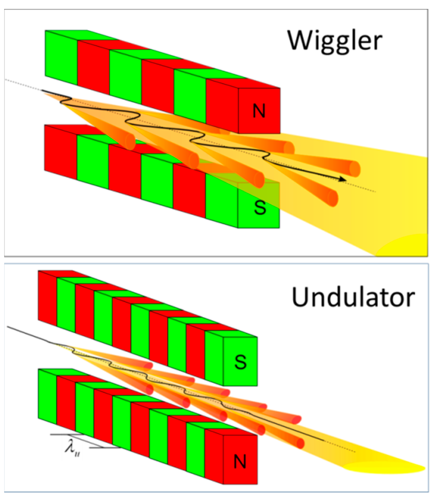
Figure 1. Schematic comparison of a wiggler and an undulator (not to scale) based on periodic magnet structure.
Applsci 12 06101 g001
Figure 2. Schematics of microwave wiggler/undulator powered by RF radiation source.
Applsci 12 06101 g002
Figure 3. Schematic of an FEL with gyrotron-powered microwave wiggler/undulator (different components not to scale).
Applsci 12 06101 g003
Figure 4. Classification of RF wigglers/undulators.
Applsci 12 06101 g004
Figure 5. Schematic of the LDSS and basic parameters used in [60]. Reprinted with permission from Ref. [60]. Copyright 2019 American Physical Society. Input laser pulse: 215 mJ, 6 ns, peak intensity at wafer 3.5 MW/cm2, energy density 15.3 mJ/cm2; incident gyrotron pulse 525 kW, 3 µs; output pulse 410 kW, 9 ns.
Applsci 12 06101 g005
Figure 6. High-gradient mm-wave accelerating cavity test setup. Reprinted with permission from Ref. [59]. Copyright 2020 American Institute of Physics.
Applsci 12 06101 g006
Publisher’s Note: MDPI stays neutral with regard to jurisdictional claims in published maps and institutional affiliations.