Article

Torque-Enhanced Phase Current Detection Schemes for Multiphase Switched Reluctance Motors with Reduced Sensors

1
College of Electrical and Information Engineering, Hunan University, Changsha 410082, China
2
College of Electrical and Information Engineering, Hunan Institute of Engineering, Xiangtan 411104, China
*
Authors to whom correspondence should be addressed.
Appl. Sci. 2022, 12(12), 5956; https://doi.org/10.3390/app12125956
Submission received: 10 May 2022 / Revised: 7 June 2022 / Accepted: 9 June 2022 / Published: 11 June 2022
(This article belongs to the Section Electrical, Electronics and Communications Engineering)

Abstract

:
An n/2-sensor-based and an (m + 1)/2-sensor-based phase current detection scheme are proposed for even-numbered switched reluctance motors (EMSRMs) with n phases and odd-numbered switched reluctance motors (OMSRMs) with m phases. For the EMSRMs, the phases are divided into n/2 groups each of which includes two phases furthest from each other, and the lower dc bus is split into n/2 + 1 buses such that the currents through the lower switches of a group flow through a bus whose current is detected by a sensor. For the OMSRMs, the phases are divided into (m + 1)/2 groups and the currents through the lower switches of a group are detected by a multiplexed sensor without converter modification; the phase grouping is generalized as an optimization problem considering the volume and measuring range of the sensors. The schemes can detect the magnetization and freewheeling phase currents under multiphase excitation without pulse injection and voltage penalty. Compared to the existing schemes using cross-winding sensors, the proposed schemes can increase the motor torque by extending the phase conduction region. In addition, the proposed scheme for EMSRMs can combine the low-cost low-side shunt current sensing technique, and the proposed scheme for OMSRMs can increase the current sensing resolution. Simulations are carried out to validate the two proposed schemes. The proposed (m + 1)/2-sensor-based scheme is further verified experimentally.

1. Introduction

In recent decades, the switched reluctance motor (SRM) has drawn increasing attention in some applications such as the electric vehicle, due to its many merits such as high reliability, low cost, and wide operating range [1,2,3]. For SRMs, phase current detection plays a crucial role in phase current control such as hysteresis current control [4], PI current control [5], predictive current control [6,7], diagnosis of power converter [8,9], and most sensorless position estimation methods [10]. Conventionally, each phase of an SRM needs a hall effect sensor along with a signal-conditioning circuit and an analog-to-digital channel to detect its current, and thus current detection of a phase is completely independent of that of any other phase. However, the hall effect sensor is one of the bulkiest and most expensive components in an SRM drive. In addition, the phase current consistency and reliability of the drive will be reduced with the number of the current sensing circuits. Therefore, phase current detection for SRMs with fewer sensors has aroused increasing interest in the last decade.
Most of the existing current detection methods with reduced sensors can be classified into one-sensor-based and two-sensor-based methods. In [11], the phase current sensing method using reduced sensors is firstly applied to the SRM drives. The lower dc bus of asymmetric half-bridge converter (AHBC) is split into two buses, such that a single current sensor is used to sense the sum of the currents through the commutating switches of all the motor phases. In the two-phase excitation region, the current samplings of the two phases are staggered in time, and the AHBC is temporarily forced into a “sense state” at each sampling instant. In the “sense state” of a phase, only the current of this phase can pass through the single sensor and thus be detected. The insertions of the “sense states” are implemented by adding some complex logic circuits. In [12], the insertions are achieved by injecting double phase-shifted PWM signals with the same frequency and duty cycle into the drive signals of the down switches of the two phases simultaneously excited, thus avoiding the additional circuits. Combined with the phase current reconstruction scheme in [12], a wavelet packet decomposition-based fault diagnosis scheme is developed in [13], and a sensorless rotor position estimation method is proposed in [14]. However, all the insertions above will lead to voltage penalty, additional current ripples, and additional switching losses. In [15], the voltage penalty and the additional current ripples are avoided based on the proposed power converter, which adds an excitation current path for each phase compared to the AHBC. However, the phase current reconstruction requires injecting four high-frequency pulses into the drive signals of four switches, which will result in more extra switching losses. Moreover, all the one-sensor-based methods above cannot detect the phase currents in demagnetization. In [16], a one-sensor-based method that can reconstruct the magnetization and also the demagnetization phase currents is proposed for three-phase SRMs based on a four-leg power converter. However, the problems of voltage penalty, additional current ripples, and additional switching losses still exist due to the pulse injection. Additionally, the freewheeling phase currents cannot be detected.
In [17,18,19], by limiting the number of the phases simultaneously conducted to no greater than two, the phase currents of a three- or four-phase SRM are reconstructed by using two crossing winding sensors and by solving two linear equations related to the non-zero phase currents and the sensed currents. In [17], each sensor detects the sum of all the phase currents, while in [18,19] each sensor measures the sum of two-phase currents. By using the two-sensor-based schemes, both the magnetization, freewheeling, and demagnetization phase currents can be reconstructed without pulse injection, voltage penalty, and modification to the AHBC. However, the limitation would most likely compromise the available maximum motor torque, especially at high speeds and especially for multiphase SRMs. In [20], a two-sensor-based scheme for four-phase SRMs is put forward by splitting the upper and lower dc buses of the AHBC into two buses. All the currents through the commutating switches of phases B and D flow through an upper bus and the bus current are detected by a sensor. All the currents through the commutating switches of phases A and C flow through a lower bus and the bus current are detected by another sensor. This scheme can reconstruct the magnetization and freewheeling phase currents without pulse injection and voltage penalty. In [21], the lower dc bus of the AHBC is split into two buses whose currents are detected by two sensors, respectively. One bus current is equal to the sum of the currents through the lower switches, and the other bus current is equal to the sum of the currents through the lower diodes. This scheme can enhance the fault detection ability, but the issue of voltage penalty still exists. In [22], the positions of the power switches in the AHBC are rearranged and two sensors are used to detect the currents through the middle points of the upper and lower dc buses, respectively. This method owns superior thermal stress distribution but still requires pulse injection.
All the current detection methods mentioned above with reduced sensors do not consider the multiphase excitation which is common in multiphase SRM drives to suppress torque ripple and increase motor torque, and thus are not very suitable for multiphase SRM drives. To detect the phase currents under multiphase excitation with reduced sensors, several methods are proposed in recent years. In [19], two multiplexed sensors are used to reconstruct the phase currents under the three-phase excitation in five- and six-phase SRM drives which are made equivalent to two independent drives with a single sensor. Phase reconstruction of each independent drive can be achieved using the method in [12,14]. In [23], n/2 and (m + 1)/2 crossing-winding sensors are used to detect the phase currents in an even-numbered multiphase SRM (EMSRM) with n phases and in an odd-numbered multiphase SRM (OMSRM) with m phases, respectively. Intact phase currents can be reconstructed without pulse injection, voltage penalty, converter modification, additional switching losses, and additional current ripples. However, the methods are not quite suitable for high-speed operation. The reason for this will be detailed in the following sections.
The rest of the paper is organized as follows: Section 2 reviews the conventional current detection scheme where each phase current is independently detected by a hall effect sensor. The proposed current detection schemes for EMSRMs and OMSRMs are described in detail in Section 3. In Section 4, the simulation results by using the proposed methods and the methods in [23] are presented and analyzed. In Section 5, the experiments with the proposed method for OMSRMs are conducted. Finally, conclusions are drawn in Section 6.

2. Conventional Current Detection Scheme with Np Hall Effect Sensors

For an Np-phase SRM, Np hall effect sensors are usually used. Each phase conductor vertically passes through the aperture of a sensor, and each phase current is detected individually by a sensor. The AHBC with four hall effect current sensors for a four-phase 8/6 SRM is shown in Figure 1, where iA, iB, iC, and iD are the currents of phases A, B, C, and D, respectively; LA, LB, LC, and LD represent the phase inductances; Udc is the dc-link voltage; HS1, HS2, HS3, and HS4 denote the current sensors.
There are four operation modes for each phase in an AHBC. Take phase A for example, with the power switches S1 and S2 both on, positive dc-link voltage is applied to the phase winding, and phase A is in the magnetization mode as shown in Figure 2a; with S1 and S2 both off, negative dc-link voltage is applied and demagnetization mode is formed as shown in Figure 2b; with only one switch on, zero voltage is applied; with only the lower switch on, freewheeling mode I is established as shown in Figure 2c; with only the upper switch on, the phase is in freewheeling mode II as shown in Figure 2d.
i A = i HS 1 ; i B = i HS 2 ; i C = i HS 3 ; i D = i HS 4

3. Proposed Current Detection Schemes with Reduced Sensors

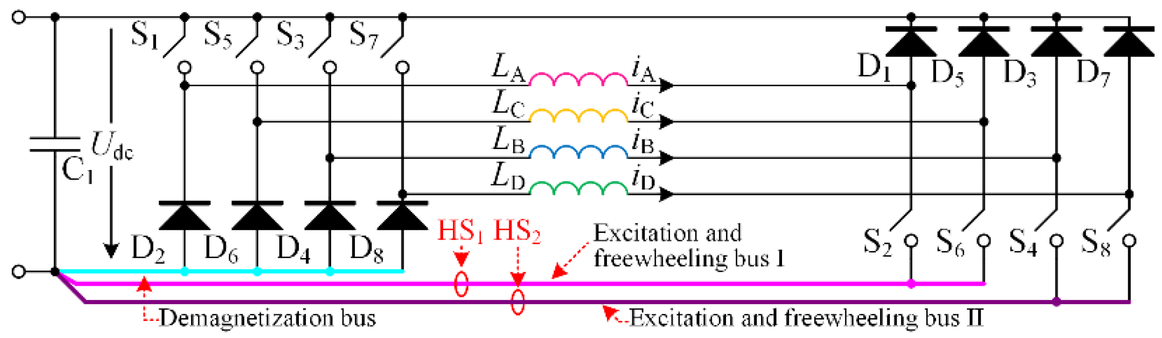
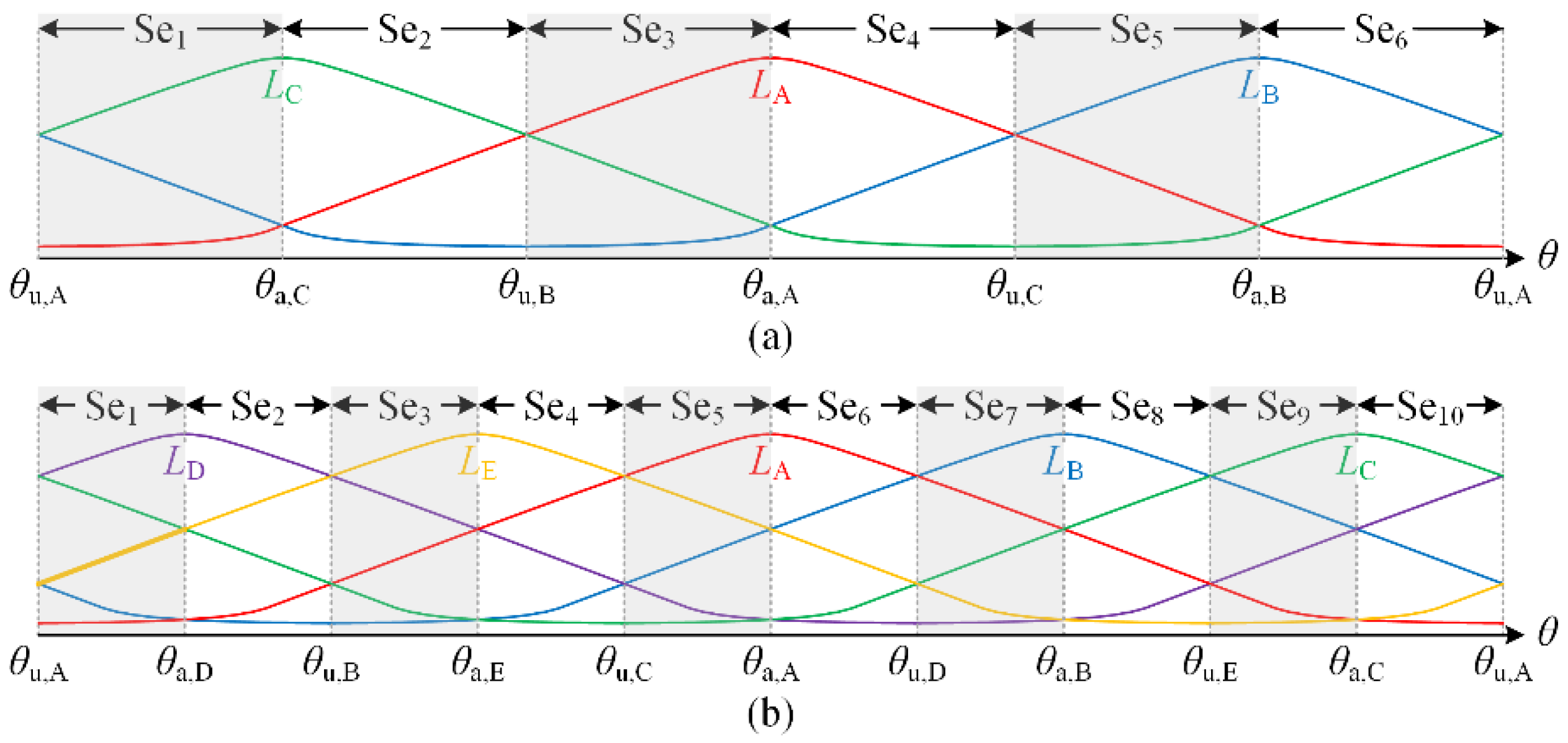
3.1. Phase Grouping in EMSRMs

For an SRM, the minimum absolute value of phase-shift angle, (i.e., absolute value of the phase-shift angle between two adjacent phases) can be derived as
θ ps , min = τ r / N p
where τr denotes the electrical cycle [24]. The phase-shift angle between two arbitrary phases can be given by
θ ps = θ ps , min Z 1 , Z 1 = ± 1 , ± 2 , , ± E ( N P / 2 )
where E (·) denotes the floor function.
Phase number of an EMSRM can be expressed as
N p = 2 Z 2 , Z 2 2 and Z 2 is an integer
Combining (2)–(4), the phase-shift angle can be obtained by
θ ps = τ r Z 1 / ( 2 Z 2 )
When Z1 = Z2, the angle equals half of the electrical cycle as shown in
θ ps = τ r / 2 , Z 2 = Z 1
The phase-shift angle between the aligned and unaligned rotor positions of one phase also equals half of the electrical cycle. Therefore, for two phases j and k which are furthest from each other in an EMSRM, the aligned and unaligned positions of phase j exactly coincide with the unaligned and aligned positions of phase k, respectively. The torque direction of phase j is opposite to that of phase k as long as the rotor is not at the aligned and unaligned positions of these two phases. Simultaneous conduction of these two phases should be avoided to guarantee that all the phase torques are in the same direction of the motor torque reference, facilitating the use of a single time-multiplexed sensor to sense the currents of these two phases. Thus, we divide the phases in an EMSRM into Np/2 groups in each of which two phases are furthest from each other and are supposed to be conducted asynchronously.
Take the four-phase 8/6 SRM for example, all aligned positions of this SRM are shown in Figure 3, from which we can see that phase C is the furthest phase from phase A, and the aligned and unaligned positions of phase C exactly coincide with the unaligned and aligned positions of phase A, respectively. Thus, phases A and C should be contained in a phase group. Similarly, phases B and D should be included in another group.

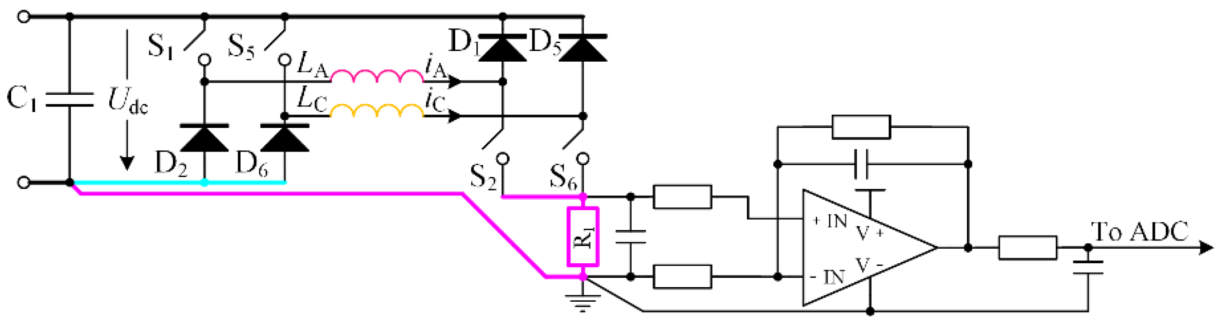
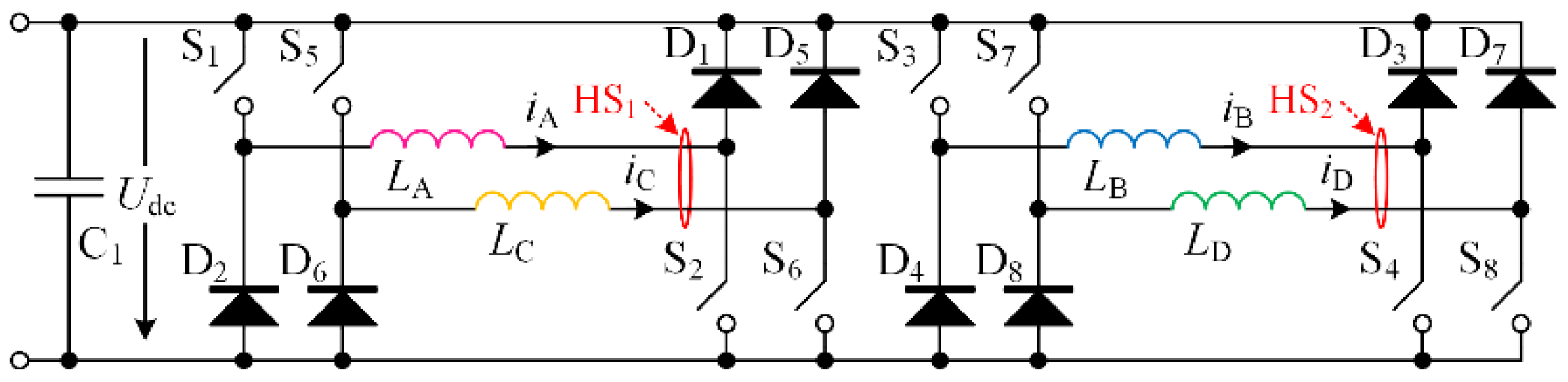
3.2. Sensors-Based Current Detection Scheme for EMSRM

Based on the phase grouping principle, the lower dc bus of the AHBC is split into Np/2 + 1 buses including a demagnetization bus for all phases, as well as Np/2 buses for excitation and freewheeling, each of which is shared by a phase group. At any time, the demagnetization current of any phase can only flow through the demagnetization bus, and only one phase current in excitation mode or freewheeling mode II will flow through the excitation and freewheeling bus. Therefore, the current through each excitation and freewheeling bus and thus the current of each phase in the corresponding group can be detected by a single current sensor.
Take the four-phase SRM for example again, the modified converter is shown in Figure 4, where phases A and C share the excitation and freewheeling bus I while phases B and D share the excitation and freewheeling bus II. The converter for phases A and C is independent of that for phases B and D. In the expected conduction region (ECR) of phase C, power switches S1 and S2 for phase A are both turned off. Whether the turn-off is advanced enough to force the phase A current to zero before the region, the bus I is occupied by phase C exclusively in the region, and thus the phase C current can be detected by the sensor HS1 with the lower switch S6 on. Possible current paths through the bus I in the ECR of phase C are shown in Figure 5, from which we can see that the possible residual current of phase A will not flow through the bus I and affect the phase C current sampling. Thus, currents of phases A and C can be completely detected by a single sensor. Similarly, currents of phases B and D can be measured by HS2.
The measured currents can be expressed as
{ i HS 1 = D S 2 i A θ R con , A * i HS 1 = D S 6 i C θ R con , C * i HS 2 = D S 4 i B θ R con , B * i HS 2 = D S 8 i D θ R con , D *
where R con , A * , R con , B * , R con , C * and R con , D * denote the ECRs of phases A, B, C, and D, respectively, DS1, DS2, DS3, and DS4 denote the drive signals of the power switches S1, S2, S3, and S4, respectively, and the signal values of 1 and 0 indicate the on and off states of the corresponding switch, respectively. The phase currents at sampling points can be obtained by
{ i AS [ k ] = i HS 1 θ R con , A * i BS [ k ] = i HS 2 θ R con , B * i CS [ k ] = i HS 1 θ R con , C * i DS [ k ] = i HS 2 θ R con , D *
if the samplings are conducted with the corresponding switches turned on. In (8), k denotes the number of the sampling step.
Considering that the current through the bus I or II always flows towards the ground of the power supply, the bus currents could also be detected by using shunt resistors with non-isolated single-supply non-inverting amplifiers as shown in Figure 6. The current detection with shunt resistors is much more cost-effective than that with the hall effect sensors.
The actual conduction region (ACR) of each phase includes the ECR and the demagnetization region after the ECR. One may note that if the ACR can be guaranteed to be smaller than τr/2, the phase currents in the four operation modes can all be detected by directly passing the phase conductor through the hall effect sensor without splitting the lower dc bus. However, this constraint is very likely to severely compromise the maximum motor torque at high speeds. Additionally, the low-cost shunt-based current detection scheme cannot be applied. By not detecting the demagnetization currents, only the ECR is required to be smaller than τr/2 and the ACR can be much larger than τr/2 at high speeds.

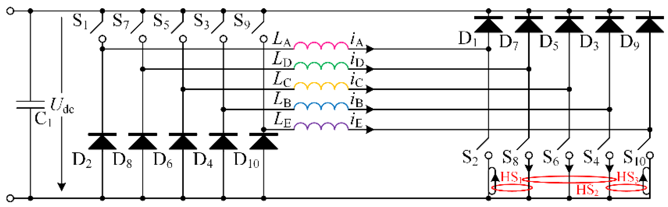
3.3. (Np + 1)/2 Hall Effect Sensors-Based Current Detection Scheme for OMSRM

Phase number of an OMSRM can be expressed as
N p = 2 Z 3 + 1 , Z 3 1   and Z 3 is an integer
In combining (2), (3) and (9), we obtain
θ ps = τ r Z 1 / ( 2 Z 3 + 1 )
Clearly, there exists
θ ps τ r / 2
Therefore, the positive torque region of a phase overlaps with that of any other phase, and thus a phase and any other phase could be excited at the same time to generate a positive or negative motor torque. However, it is found that there are at most (Np + 1)/2 phase torques in the same direction at any rotor position, and thus at most (Np + 1)/2 multiplexed current sensors could be enough to detect all the phase currents. For demonstration, phase inductance curves of a three-phase SRM and a five-phase SRM are, respectively, shown in Figure 7a,b, where θ is the rotor position; θu,A, θu,B, θu,C, θu,D, and θu,E denotes the unaligned positions of phases A, B, C, D, and E, respectively; θa,A, θa,B, θa,C, θa,D, and θa,E represent the aligned positions; Se1, Se2, …, Se10 indicate the position sectors.
It can be observed that an electrical cycle of the three-phase SRM is divided into six sectors by the unaligned and aligned positions of all phases, two inductance curves are rising in the three sectors highlighted by gray rectangles and two inductance curves are falling in the other three sectors. Similarly, an electrical cycle of the five-phase SRM is divided into ten sectors, three inductance curves are ascending in the five sectors marked by gray rectangles and three inductance curves are descending in the other five sectors. In addition, the phases with the same torque direction are consecutively adjacent. Therefore, there are only Np combinations of the (Np + 1)/2 phases with the same torque direction. For the three-phase SRM, the three combinations are phases A and B, phases B and C, as well as phases C and A. For the five-phase SRM, the five combinations are phases A, B, and C; phases B, C, and D; phases C, D, and E; phases D, E, and A; as well as phases E, A, and B.
We take the five-phase SRM as an example to demonstrate the process of determining the current sensor multiplexing scheme for an OMSRM. Relationships between the phase currents and the currents measured by the three hall effect sensors (HS1, HS2, and HS3) in the five-phase SRM drive can be expressed by
K 5 p [ i A i B i C i D i E ] T = [ K 11 K 12 K 13 K 14 K 15 K 21 K 22 K 23 K 24 K 25 K 31 K 32 K 33 K 34 K 35 ] [ i A i B i C i D i E ] T = [ i HS 1 i HS 2 i HS 3 ]
where K5p denotes the coefficient matrix, each element of which can be −1, 0, or 1. The sign of an element indicates the direction of the phase current-carrying conductor through the sensor. For the five combinations, (12) can be simplified to (13)–(17), respectively.
K 5 pABC [ i A i B i C ] T = [ i HS 1 i HS 2 i HS 3 ] T
K 5 pBCD [ i B i C i D ] T = [ i HS 1 i HS 2 i HS 3 ] T
K 5 pCDE [ i C i D i E ] T = [ i HS 1 i HS 2 i HS 3 ] T
K 5 pDEA [ i A i D i E ] T = [ i HS 1 i HS 2 i HS 3 ] T
K 5 pEAB [ i A i B i E ] T = [ i HS 1 i HS 2 i HS 3 ] T
where K5pABC, K5pBCD, K5pCDE, K5pDEA and K5pEAB are five 3   ×   3 submatrices of the matrix K5p. K5pABC consists of the first three column vectors; K5pBCD consists of the middle three column vectors; K5pCDE consists of the last three column vectors; K5pDEA consists of the first, fourth, and fifth column vectors; K5pEAB consists of the first, second, and fifth column vectors.
The phase currents can be uniquely calculated from the measured currents if the five submatrices are full rank as in
r a n k ( K 5 pABC ) = r a n k ( K 5 pBCD ) = r a n k ( K 5 pCDE ) = r a n k ( K 5 pDEA ) = r a n k ( K 5 pEAB ) = 3
where rank (·) denotes the function for calculating the rank of a matrix. The original matrix should be row full rank first as in
r a n k ( K 5 p ) = 3
All coefficient matrices satisfying (19) and (18) can be found directly by evaluating all the possible matrices. However, these matrices differ significantly from each other. Three exemplary matrices are given as follows
K 5 p , e 1 = [ 0 0 1 1 1 0 1 1 0 1 1 1 1 1 0 ]
K 5 p , e 2 = [ 1 0 0 1 0 0 1 1 1 0 0 1 0 0 1 ]
K 5 p , e 3 = [ 1 0 0 1 0 0 1 1 1 0 0 1 0 0 1 ]
We can see that K5p,e1 has the most number of non-zero elements and thus the phase current calculation is the most complicated. More non-zero elements also mean more wires needed to pass through the sensors and higher requirements for the aperture size of the sensor. Therefore, K5p,e1 should be excluded first.
The vast majority of hall effect sensors can detect bidirectional currents, and thus the hall effect sensors in most SRM drives are bidirectional though the phase currents are unidirectional. The measuring range of a bidirectional sensor is symmetric with respect to the measured current of 0 A. With K5p,e2, all conductors pass through the sensors in the same direction, and thus only half the range of each sensor is used. With K5p,e3, two conductors pass through the sensors HS1 and HS3 in a different direction, and thus the measured current ranges are also symmetric with respect to 0 A; two conductors pass through the sensor HS2 in a direction, and the other one in the other direction, and the measured current range, two-thirds and one-third of which are respectively positive and negative, is not symmetric with respect to 0 A but still matches the measuring range much better than that with K5p,e3. Therefore, K5p,e3 is preferred compared with K5p,e2 since the measuring range can be used much more fully, and thus the current sensing resolution is much higher.
By comparatively analyzing these three matrices, we introduce an additional constraint as in (23) and define the number of non-zero elements in the coefficient matrix as the objective function J expressed as (24).
s u m ( K 5 p ( j ; : ) ) { 0 , 1 } , j { 1 , 2 , 3 }
J = s u m ( a b s ( K 5 p ) )
In the two equations, sum(·) denotes the function for calculating the sum of all elements of a matrix, abs (·) denotes the function that creates a new matrix consisting of the absolute values of all elements of the input matrix, K5p (j;:) denotes the jth row vector of K5p. By satisfying the additional constraint, the number of conductors through each sensor in one direction is the nearest to that in the other direction, and thus the measured current range can best fit the measuring range.
Finally, the multiplexing scheme for the three sensors in a five-phase SRM drive can be determined by solving the optimization problem represented by
min J = s u m ( a b s ( K 5 p ) ) s . t . { r a n k ( K 5 p ) = 3 r a n k ( K 5 pABC ) = r a n k ( K 5 pBCD ) = r a n k ( K 5 pCDE ) = r a n k ( K 5 pDEA ) = r a n k ( K 5 pEAB ) = 3 s u m ( K 5 p ( j ; : ) ) { 0 , 1 } , j { 1 , 2 , 3 }
Actually, K5p,e3 is an optimized matrix and is used in this paper. By selecting K5p,e3, the schematic diagram of the AHBC with the three multiplexed sensors is shown in Figure 8.
Substituting the five submatrices of K5p,e3 back into (13)–(17), the phase currents can be calculated when the corresponding lower switches are turned on.
The current sensor multiplexing scheme for other OMSRM with different phase numbers can be formulated by solving an optimization problem similar to (25).

3.4. Current Control without Sampling Demagnetization Current

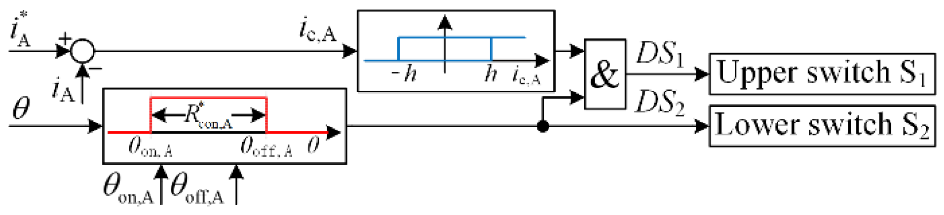
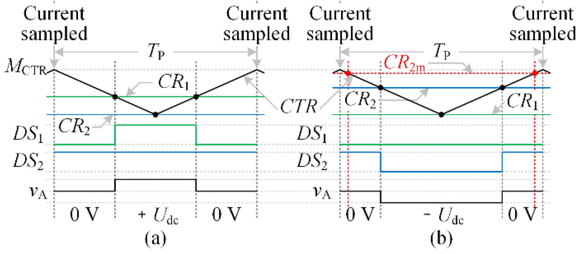
3.4.1. Soft Current Chopping Control (SCCC)

When applying SCCC, only one switch is controlled and the other one is left turned on during the ECR. By only controlling the upper switch for chopping, SCCC can be implemented without sampling demagnetization current. The principle of SCCC with the upper switch controlled is illustrated in Figure 9, where i A * and ie,A are the reference and error currents of phase A, respectively; h is the hysteresis-band width; θ is the rotor angle; θon,A, and θoff,A denote the turn-on and turn-off angles of phase A, respectively.

3.4.2. Voltage Pulse-Width Modulation Control (VPC)

This scheme controls the current by regulating the average phase voltage through PWM. An average voltage can be generated by applying positive and negative dc-link voltages at different times of a PWM cycle. A positive average voltage can also be generated by applying positive dc-link voltage and zero voltage at different times, while a negative average voltage can also be generated by applying negative dc-link voltage and zero voltage at different times. The voltage generation with zero voltage is preferred due to fewer switching times and smaller current ripples. The phase current sampling can be performed at the overflow or underflow of the PWM counter, and the duration of each sampling is usually far shorter than the PWM cycle.
In order to apply VPC without sampling demagnetization current, a PWM configuration scheme with a current sampling timing scheme based on the configuration is proposed and shown in Figure 10, where CR1 and CR2 are the comparison values for the drive signals DS1 and DS2, respectively; CTR, MCTR, and TP denote the PWM counter, maximum value of the counter and PWM cycle, respectively; vA is the instantaneous phase A voltage; CR2m is the upper limit for CR2. The duty cycle depends on the amplitude relationship between the PWM counter and the corresponding comparison value. Current sampling is synchronized with the counter overflow. In the ECR, the upper limit CR2m should be smaller than MCTR and is chosen such that the lower switch can be fully turned on at an overflow of the PWM counter in the case that a very large negative average voltage is required to be applied.

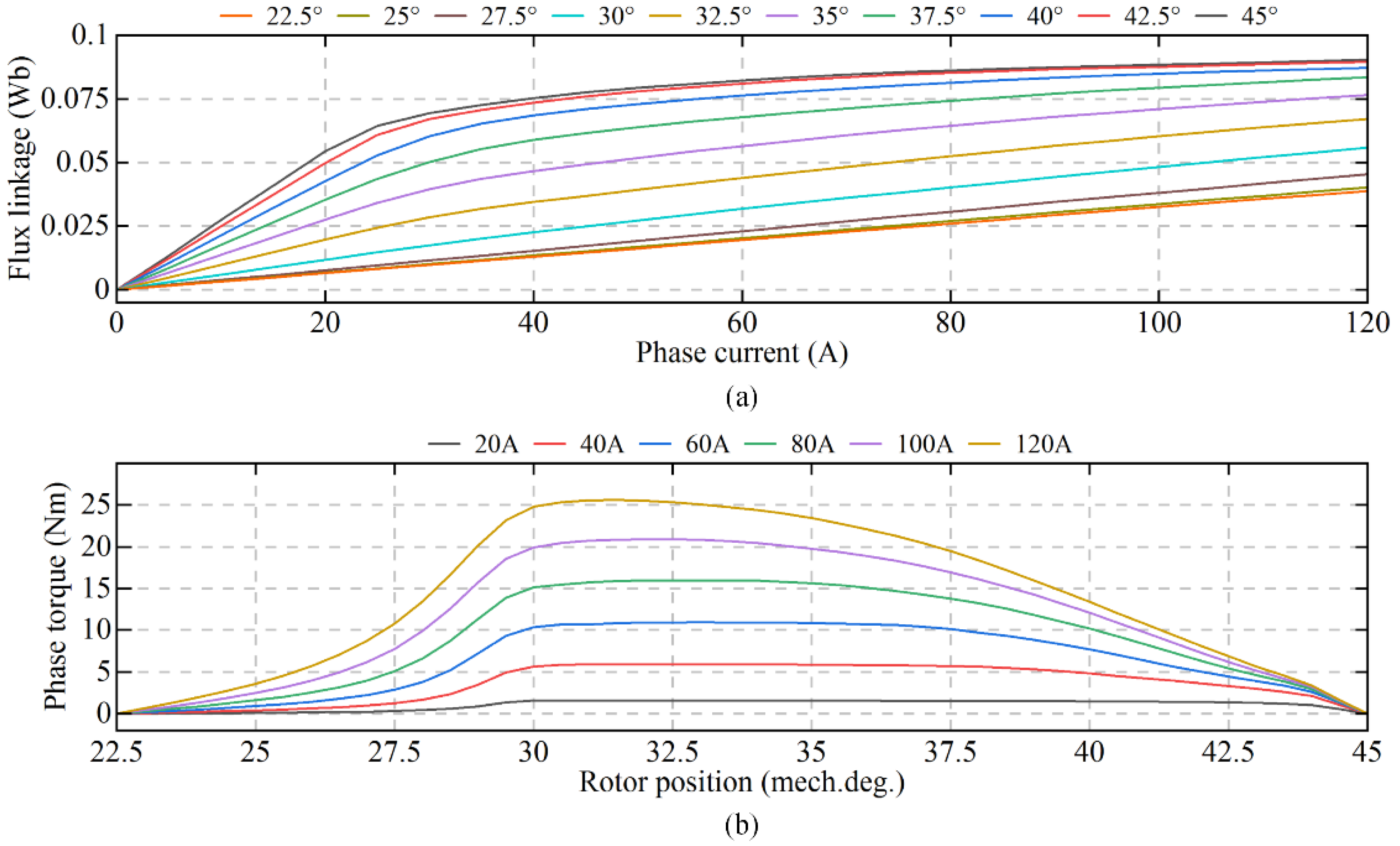
4. Simulation Verification

The Np/2 hall effect sensors-based and the (Np + 1)/2 hall effect sensors-based phase current detection schemes in the literature [23] are the most relevant schemes to the proposed schemes and thus are chosen as the baseline schemes in this section. The proposed schemes are verified and compared to the baseline schemes by simulation in MATLAB/SIMULINK environment.

4.1. Simulation Verification of the Np/2 Sensors-Based Schemes

In this subsection, all simulations are carried out on the pre-built SIMULINK model of a 75 kW four-phase 8/6 SRM. The baseline scheme for the four-phase SRM is illustrated in Figure 11, where the sampled phase currents could be derived by (8) irrespective of the switching states of the lower switches.
In all simulations in this subsection, the VPC in [6] is adopted for the phase current regulation; the PWM modulators are configured and the phase current sampling points are arranged according to Figure 10. The average phase voltage is predicted by
V A , k + 0 . 5 , k + 1 . 5 = 3 2 [ i A , k + 1 . 5 * + i A , k 2 R s + λ A , k + 1 . 5 - λ A , k 1 . 5 T P ] - V A , k , k + 0 . 5 2
where the subscript k indicates the present time instant at an overflow of the PWM counter; the subscripts k + 0.5 and k + 1.5 indicate the time instants 0.5 TP and 1.5 Tp after the instant k, respectively; i A * denotes the phase A current reference; λA denotes the phase flux linkage; Rs denotes the phase resistance; VA,k,k + 0.5 and VA,k + 0.5,k + 1.5 denote the average voltages during [k, k + 0.5] and [k + 0.5, k + 1.5], respectively.
The Block diagram of the simulated SRM drive system using the proposal is shown in Figure 12, where i* is the current reference; UL is the lower limit for the average phase voltages; ω is the angular speed. The block diagram for the baseline scheme is similar to the one in Figure 12. Notable differences between the two diagrams are the phase current detection scheme and the value of the limit UL. Using the baseline scheme, UL is fixed to −Udc.
In all simulations with the four-phase SRM, the dc-link voltage Udc is set to 513 V; the PWM frequency is set to 5 kHz; the rotor angles of 30° and 60° mean the unaligned and aligned positions, respectively. For the simulations with the proposal, UL is set to −482 V if the phase is in the ECR and to −Udc otherwise.
Simulations at 100 rpm (i* = 60 A), 2000 rpm (i* = 20 A), and −1500 rpm (i* = 30 A) are conducted, and the actual phase currents (iA and iC), the phase currents used by the VPC (iAS and iCS), the current detected by the hall effect sensor HS1 (iHS1), as well as the drive signals (DS1, DS2, DS5, and DS6) are presented in the following three subsections. In the fourth subsection, the maximum torque-speed characteristics are obtained.

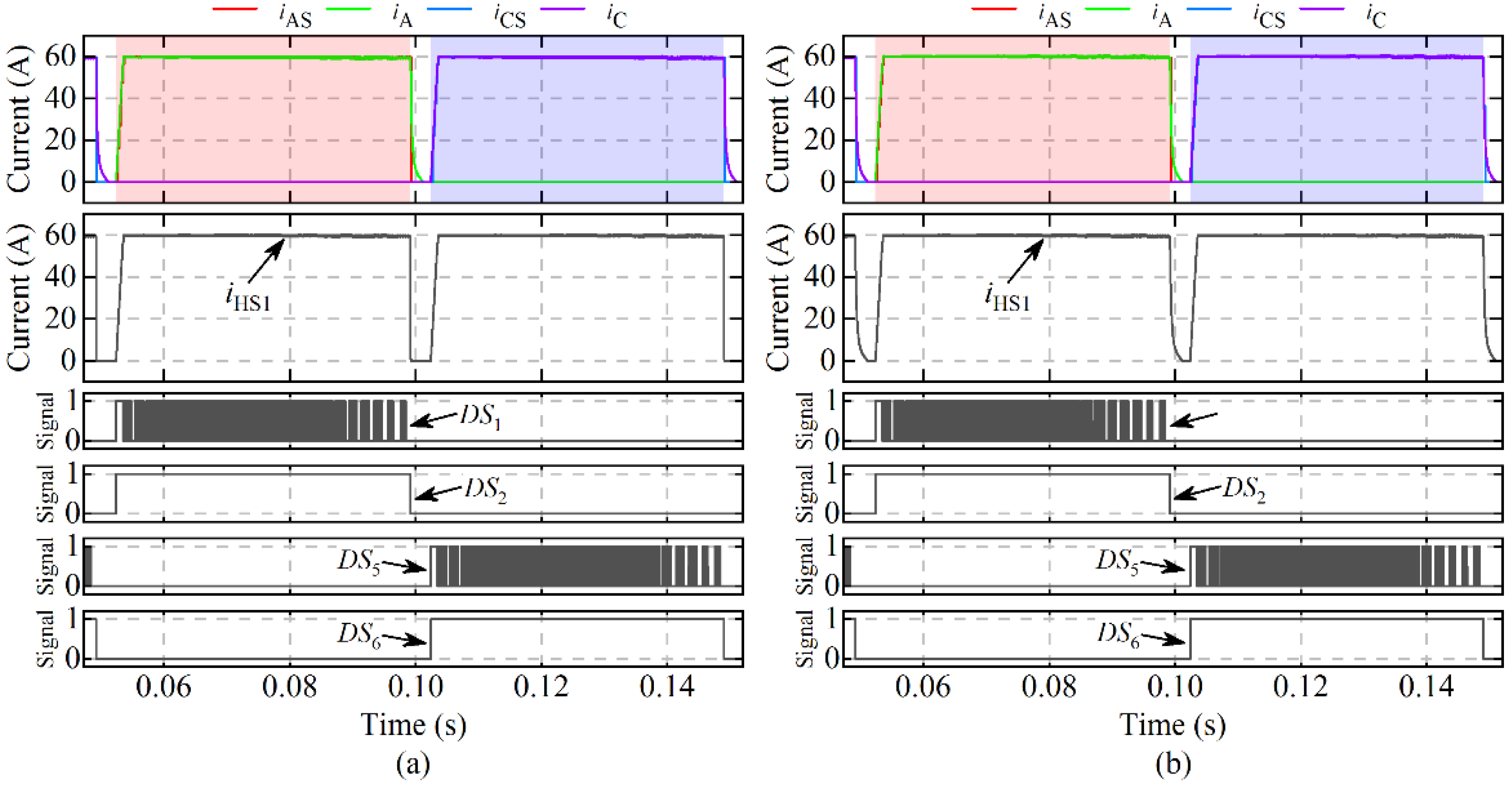
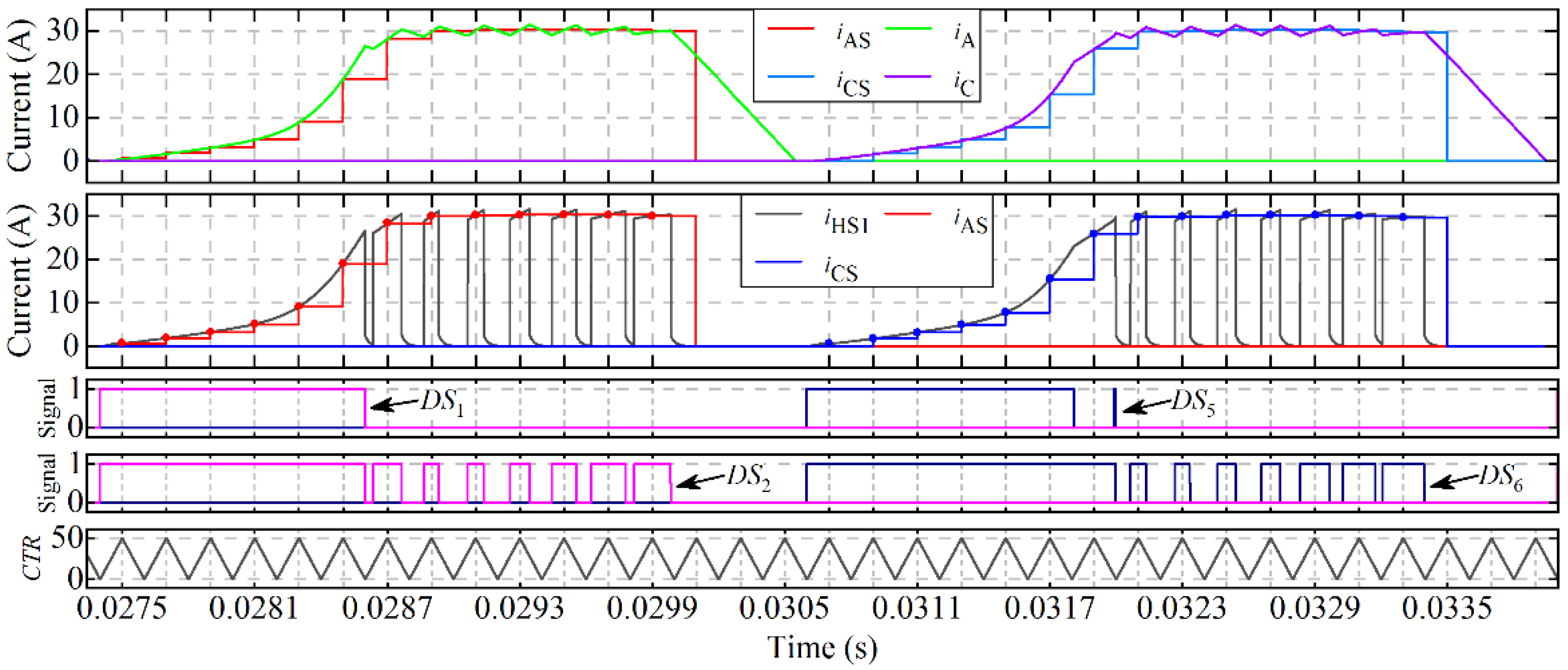
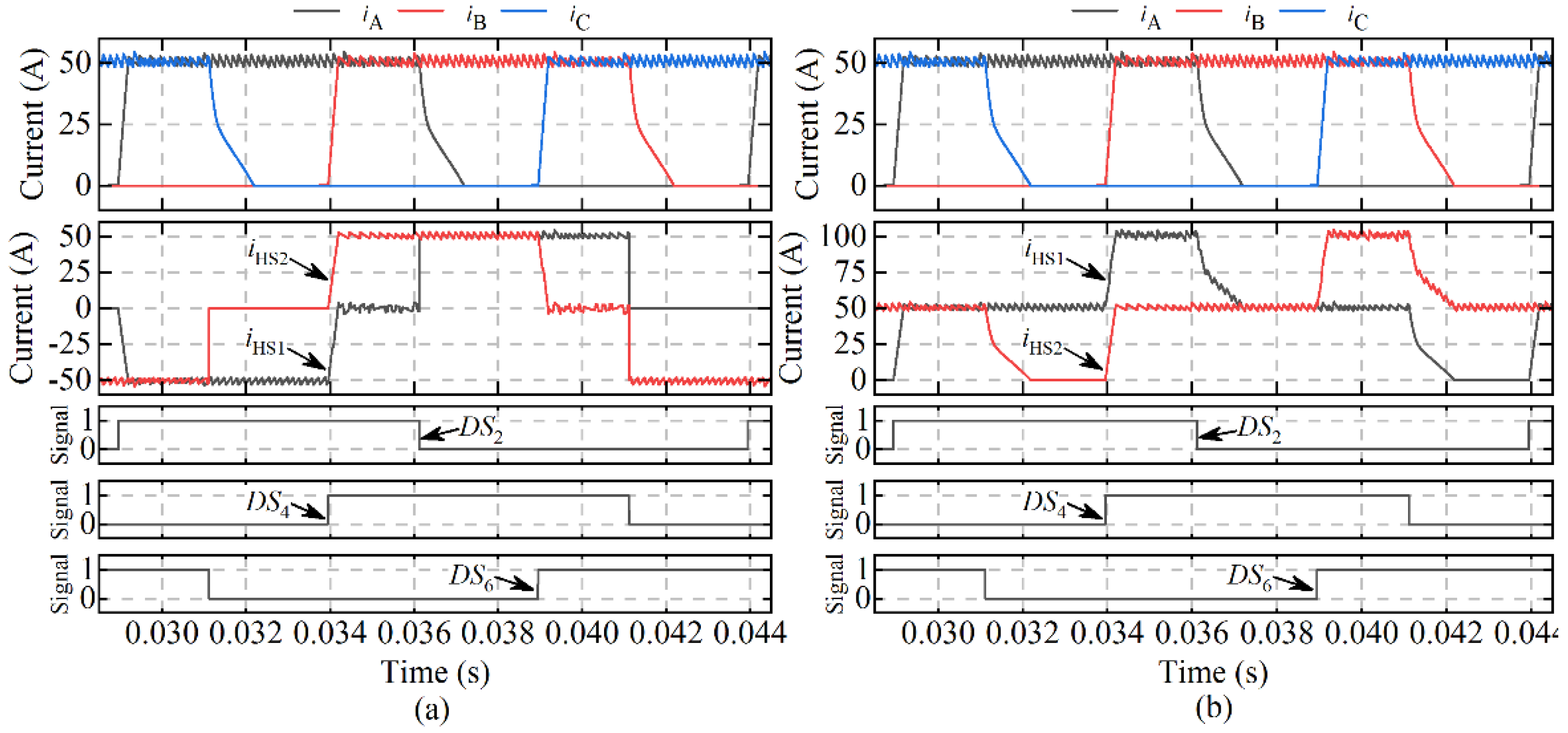
4.1.1. Simulation Results at 100 rpm (i* = 60 A)

The results are obtained with the turn-on angle of 31° and the turn-off angle of 59° and are shown in Figure 13, where the red and blue rectangular areas indicate the ECRs of phases A and C, respectively. It can be seen that the ACR of phase A does not overlap with that of phase C, the negative phase voltages are not applied, and the lower switches are kept on during the ECRs. Thus, the currents detected by the sensor HS1 using the two schemes both match the actual phase currents very well during the ECRs. The baseline method can also detect the demagnetization phase currents outside the ECRs; however, these currents are not used in the current control.

4.1.2. Simulation Results at 2000 rpm (i* = 20 A)

The turn-on and turn-off angles are set to 30° and 55°, and the results are shown in Figure 14, where the yellow rectangular area denotes the undesirable two-phase conduction region in which the ACRs of phases A and C overlap each other. High back electromotive force at the speed of 2000 rpm severely slows down the demagnetization and causes a long tail current and the unexpected overlapping region. As evident in Figure 14b, the phase C current sampled using the baseline scheme (iCS) is higher than the actual one in the overlapping region. This is because the multiplexed sensor HS1 always detects the sum of the currents of phases A and C regardless of the operation modes of these two phases. From Figure 14a, the phase C current sampled with the sensor (iCS) can still closely match the actual one, even in the overlapping region for the reason that the demagnetization current of phase A does not flow through the sensor HS1.

4.1.3. Simulation Results at −1500 rpm (i* = 30 A)

The simulated system is operating in braking mode to test the proposed scheme with demagnetization currents in the ECRs. The turn-on and turn-off angles are set to 30.5° and 55°, and the results are shown in Figure 15, from which we can see that sampling of the current through bus I is strictly guaranteed to be periodically performed when the lower switches are fully turned on. Therefore, the sampled currents (iAS and iCS) can still well match the actual currents (iA and iC) at all sampling points in the ECRs even though the current through the sensor (iHS1) cannot reflect the actual currents when the negative phase voltages are applied.

4.1.4. Maximum Torque-Speed Characteristics

The maximum torques of the four-phase SRM drive over a wide speed range from 300 rpm to 3000 rpm are obtained with a large current reference of 70 A. At each speed point, the electrical-cycle-averaged motor torques with different combinations of the turn-on and turn-off angles are derived by simulation, and the maximum torque with the corresponding angle combination is derived. By using the baseline method, the ACR must be smaller than τr/2. By using the proposed method, only the ECR must be smaller than τr/2. The maximum torques, turn-on, and turn-off angles with respect to the speed are shown in Figure 16. Clearly, the maximum torque with the proposed method is much larger than that with the baseline scheme, especially at high speeds. Quantitatively, the maximum torque with the proposal is 153% on average and 334% at the highest.

4.2. Simulation Verification of the (Np + 1)/2 Sensors-Based Schemes

In this subsection, all simulations are conducted on a 1.5 kW three-phase 12/8 SRM. Table 1 presents the main parameters of the SRM. Figure 17a,b, respectively, show the magnetization characteristics and the torque characteristics of the SRM, which are obtained by conducting finite-element analysis in ANSYS Electronics Desktop 2020 R1. The proposed and baseline schemes for the three-phase SRM are shown in Figure 18a,b, respectively.
In all simulations with the three-phase SRM, the dc-link voltage Udc is set to 72 V; the SCCC is used for the phase current control, the hysteresis band is set to 2 A and the current sampling rate is set to 50 kHz; the rotor angles of 22.5° and 45° means the unaligned and aligned positions, respectively.

4.2.1. Simulation Results at 500 rpm (i* = 50 A)

The turn-on and turn-off angles are set to 22.5° and 44°, respectively, and the results are shown in Figure 19, from which we can see that the phase currents are controlled well and thus the phase currents are detected accurately by using the proposed and the baseline current detection schemes. In addition, the currents (I1 aIiHS2) by using the proposed scheme range from about −50 A to about 50 A, while those by using the baseline scheme range from 0 A to about 100 A. Therefore, if the bidirectional hall effect current sensors are used (which is usually the case), the measuring range of the sensors by using the baseline scheme will be nearly double that by using the proposed scheme, and thus the current detection resolution by using the baseline scheme will be only about half that by using the proposed scheme.

4.2.2. Maximum Torque-Speed Characteristics

The maximum torques of the three-phase SRM drive are evaluated in a similar way to Section 4.1.4. The current reference is fixed to 120 A, and the tested speed ranges from 500 rpm to 4500 rpm. The constraints on the ACR and ECR are relaxed. In the baseline method, the ACR must be no greater than 2 τr/3. In the proposed method, only the ECR must be no greater than 2 τr/3. The maximum torques, turn-on, and turn-off angles with respect to the speed are shown in Figure 20. Again, the maximum torque with the proposed method is obviously larger than that with the baseline scheme, especially at high speeds. Quantitatively, the maximum torque with the proposal is 49.7% on average and 121% at the highest.

5. Experimental Verification

The proposed (Np + 1)/2 hall effect current sensors-based current detection scheme for OMSRMs is further verified on an experimental platform, as shown in Figure 21. The three-phase SRM in the simulations is used as the experimental motor. A magnetic powder brake is used to provide the load torque. A resolver is installed to measure the absolute rotor position. Two hall effect current sensors (LA-50P) are utilized to measure the phase current differences as illustrated in Figure 18a. Six IGBT modules (2MBI75VA-120–50) construct the AHBC. TMS320F28335 is selected as the controller.
The SCCC is applied to regulate the phase currents. The current sampling rate and the hysteresis band are set to 20 kHz and 5 A, respectively. The turn-on and turn-off angles are set to 22.5° and 44°, respectively. The dc-link voltage is set to 72 V. The experimental waveforms at 500 rpm (i* = 50 A) are shown in Figure 22. It can be seen that the difference between the phase B current and the phase A current is measured accurately by the hall effect sensor HS1, and the difference between the phase B current and the phase C current is detected precisely by the sensor HS2. All the phase currents are maintained well around the current reference of 50 A during the conduction region. Thus, the practicality of the proposed scheme is demonstrated.

6. Conclusions

This paper proposes two-phase current detection schemes using reduced current sensors for EMSRMs and OMSRMs, respectively. Using the schemes, the magnetization and freewheeling phase currents under multiphase excitation can be obtained using n/2 and (m + 1)/2 current sensors for EMSRMs with n phases and OMSRMs with m phases, respectively. Compared to the conventional phase current detection method, the proposed schemes can reduce the cost and volume of the system and improve the reliability and current sampling consistency of the system with only half or nearly half of the sensors conventionally used. Compared to the baseline methods, the proposed methods can relax the constraint on the phase conduction region width and thus increase the motor torque, especially at a high-speed operation by excluding the demagnetization currents. For EMSRMs, the proposed method can be much more cost-effective, with the ability to combine the low-side shunt current sensing technique. For OMSRMs, the proposed method can use the measuring range of the sensors more effectively and thus increase the current sensing resolution when the most common hall effect sensors are adopted. The SCCC can be implemented with the proposed methods by selecting the upper switches for chopping. The VPC can also be achieved with a small penalty on the negative average phase voltage by using the proposed PWM configuration and current sampling timing scheme, and this penalty only occurs when the negative average voltage is close to or higher than the negative dc-link voltage. In summary, the proposed methods are promising alternatives to the existing methods by considering the motor torque capability, the adaptation to different types of the current sensors, the measuring range, and the volume of the most common hall effect sensor.

Author Contributions

Conceptualization, S.S. and M.L.; methodology, H.W.; software, M.L.; validation, S.S. and Y.F.; formal analysis, Y.Z.; investigation, Y.F.; resources, Y.Z.; data curation, S.S.; writing—original draft preparation, S.S.; writing—review and editing, M.L.; visualization, S.S. and Y.F.; supervision, H.W.; project administration, H.W.; funding acquisition, Y.Z. All authors have read and agreed to the published version of the manuscript.

Funding

This research was funded by the Hunan Provincial Natural Science Foundation of China (2021JJ30185).

Institutional Review Board Statement

Not applicable.

Informed Consent Statement

Not applicable.

Data Availability Statement

Not applicable.

Conflicts of Interest

The authors declare no conflict of interest.

References

  1. Gan, C.; Wu, J.; Sun, Q.; Kong, W.; Li, H.; Hu, Y. A Review on Machine Topologies and Control Techniques for Low-Noise Switched Reluctance Motors in Electric Vehicle Applications. IEEE Access 2018, 6, 31430–31443. [Google Scholar] [CrossRef]
  2. Li, S.; Zhang, S.; Habetler, T.G.; Harley, R.G. Modeling, Design Optimization, and Applications of Switched Reluctance Machines—A Review. IEEE Trans. Ind. Appl. 2019, 55, 2660–2681. [Google Scholar] [CrossRef]
  3. Goli, C.S.; Manjrekar, M.; Essakiappan, S.; Sahu, P.; Shah, N. Landscaping and Review of Traction Motors for Electric Vehicle Applications. In Proceedings of the 2021 IEEE Transportation Electrification Conference & Expo (ITEC), Chicago, IL, USA, 21–25 June 2021; pp. 162–168. [Google Scholar]
  4. Pratapgiri, S. Comparative analysis of Hysteresis Current Control and Direct Instantaneous Torque Control of Switched Reluctance Motor. In Proceedings of the 2016 International Conference on Electrical, Electronics, and Optimization Techniques (ICEEOT), Chennai, India, 3–5 March 2016; pp. 2856–2860. [Google Scholar]
  5. Ahmad, S.S.; Narayanan, G. Linearized Modeling of Switched Reluctance Motor for Closed-Loop Current Control. IEEE Trans. Ind. Appl. 2016, 52, 3146–3158. [Google Scholar] [CrossRef]
  6. Mikail, R.; Husain, I.; Sozer, Y.; Islam, M.S.; Sebastian, T. A Fixed Switching Frequency Predictive Current Control Method for Switched Reluctance Machines. IEEE Trans. Ind. Appl. 2014, 50, 3717–3726. [Google Scholar] [CrossRef]
  7. Shen, S.; Wang, H.; Feng, Y.; Li, M.; Zhong, Y. Predictive Current Control for Switched Reluctance Motor Based on Local Linear Phase Voltage Model. Appl. Sci. 2022, 12, 1688. [Google Scholar] [CrossRef]
  8. Marques, J.F.; Estima, J.O.; Gameiro, N.S.; Cardoso, A.J.M. A New Diagnostic Technique for Real-Time Diagnosis of Power Converter Faults in Switched Reluctance Motor Drives. IEEE Trans. Ind. Appl. 2014, 50, 1854–1860. [Google Scholar] [CrossRef]
  9. Fang, C.; Chen, H.; Torkaman, H.; Anuchin, A.; Li, X. Fault Diagnosis for Power Transistors in a Converter of Switched Reluctance Motors Based on Current Features. IEEE Sens. J. 2022, 22, 1414–1423. [Google Scholar] [CrossRef]
  10. Xiao, D.; Filho, S.R.; Fang, G.; Ye, J.; Emadi, A. Position-Sensorless Control of Switched Reluctance Motor Drives: A Review. IEEE Trans. Transp. Electrif. 2022, 8, 1209–1227. [Google Scholar] [CrossRef]
  11. Kjaer, P.C.; Gallegos-Lopez, G. Single-sensor current regulation in switched reluctance motor drives. IEEE Trans. Ind. Appl. 1998, 34, 444–451. [Google Scholar] [CrossRef]
  12. Gan, C.; Wu, J.; Yang, S.; Hu, Y. Phase Current Reconstruction of Switched Reluctance Motors From DC-Link Current Under Double High-Frequency Pulses Injection. IEEE Trans. Ind. Electron. 2015, 62, 3265–3276. [Google Scholar] [CrossRef]
  13. Gan, C.; Wu, J.; Yang, S.; Hu, Y.; Cao, W. Wavelet Packet Decomposition-Based Fault Diagnosis Scheme for SRM Drives With a Single Current Sensor. IEEE Trans. Energy Convers. 2016, 31, 303–313. [Google Scholar] [CrossRef]
  14. Gan, C.; Wu, J.; Hu, Y.; Yang, S.; Cao, W.; Kirtley, J.L. Online Sensorless Position Estimation for Switched Reluctance Motors Using One Current Sensor. IEEE Trans. Power Electron. 2016, 31, 7248–7263. [Google Scholar] [CrossRef]
  15. Sun, Q.; Wu, J.; Gan, C.; Hu, Y.; Jin, N.; Guo, J. A New Phase Current Reconstruction Scheme for Four-Phase SRM Drives Using Improved Converter Topology Without Voltage Penalty. IEEE Trans. Ind. Electron. 2018, 65, 133–144. [Google Scholar] [CrossRef]
  16. Song, S.; Xia, Z.; Fang, G.; Ma, R.; Liu, W. Phase Current Reconstruction and Control of Three-Phase Switched Reluctance Machine With Modular Power Converter Using Single DC-Link Current Sensor. IEEE Trans. Power Electron. 2018, 33, 8637–8649. [Google Scholar] [CrossRef]
  17. Han, G.; Chen, H.; Shi, X.; Wang, Y. Phase current reconstruction strategy for switched reluctance machines with fault-tolerant capability. IET Electr. Power Appl. 2017, 11, 399–411. [Google Scholar] [CrossRef]
  18. Han, G.; Chen, H.; Guan, G. Low-cost SRM drive system with reduced current sensors and position sensors. IET Electr. Power Appl. 2019, 13, 853–862. [Google Scholar] [CrossRef]
  19. Gan, C.; Sun, Q.; Wu, J.; Shi, C.; Hu, Y. A Universal Two-Sensor Current Detection Scheme for Current Control of Multiphase Switched Reluctance Motors With Multiphase Excitation. IEEE Trans. Power Electron. 2019, 34, 1526–1539. [Google Scholar] [CrossRef]
  20. Gan, C.; Sun, Q.; Jin, N.; Tolbert, L.M.; Ling, Z.; Hu, Y.; Wu, J. Cost-Effective Current Measurement Technique for Four-Phase SRM Control by Split Dual Bus Line Without Pulse Injection and Voltage Penalty. IEEE Trans. Ind. Electron. 2018, 65, 4553–4564. [Google Scholar] [CrossRef]
  21. Peng, W.; Gyselinck, J.J.C.; Ahn, J.W.; Lee, D.H. Minimal Current Sensing Strategy for Switched Reluctance Machine Control With Enhanced Fault-Detection Capability. IEEE Trans. Ind. Appl. 2019, 55, 3725–3735. [Google Scholar] [CrossRef]
  22. Xu, S.; Chen, H.; Yang, J.; Dong, F. Comparative evaluation on switched reluctance motor drive with different phase current sensing methods. IET Electr. Power Appl. 2019, 13, 1964–1975. [Google Scholar] [CrossRef]
  23. Sun, Q.; Wu, J.; Gan, C.; Guo, J. A Multiplexed Current Sensors-Based Phase Current Detection Scheme for Multiphase SRMs. IEEE Trans. Ind. Electron. 2019, 66, 6824–6835. [Google Scholar] [CrossRef]
  24. Nasirian, V.; Davoudi, A.; Kaboli, S.; Edrington, C.S. Excitation Shifting: A General Low-Cost Solution for Eliminating Ultra-Low-Frequency Torque Ripple in Switched Reluctance Machines. IEEE Trans. Magn. 2013, 49, 5135–5149. [Google Scholar] [CrossRef]
Figure 1. Asymmetric half-bridge converter (AHBC) with four hall effect current sensors for a four-phase 8/6 switched reluctance motor (SRM).
Applsci 12 05956 g001
Figure 2. Operation modes of AHBC. (a) Excitation mode. (b) Demagnetization mode. (c) Freewheeling mode I. (d) Freewheeling mode II.
Applsci 12 05956 g002
Figure 3. Aligned positions of the four-phase 8/6 SRM. (a) Phase A. (b) Phase B. (c) Phase C. (d) Phase D.
Applsci 12 05956 g003
Figure 4. Modified AHBC with two current sensors for the four-phase SRM.
Applsci 12 05956 g004
Figure 5. Possible current paths through bus I in the expected conduction region of phase C. (a) Phase C in excitation mode. (b) Phase C in freewheeling mode I.
Applsci 12 05956 g005
Figure 6. Current detection circuit using a shunt resistor with non-isolated single-supply non-inverting amplifier.
Applsci 12 05956 g006
Figure 7. Phase inductance curves. (a) Of a three-phase SRM. (b) Of a five-phase SRM.
Applsci 12 05956 g007
Figure 8. AHBC with three multiplexed current sensors for a five-phase SRM.
Applsci 12 05956 g008
Figure 9. Block diagram of soft current chopping control.
Applsci 12 05956 g009
Figure 10. PWM configuration and current sampling timing. (a) Positive average phase voltage. (b) Negative average phase voltage.
Applsci 12 05956 g010
Figure 11. The baseline current detection scheme with two multiplexed hall effect sensors for the four-phase SRM.
Applsci 12 05956 g011
Figure 12. Block diagram of the simulated SRM drive system with the proposed Np/2 sensors-based current detection scheme.
Applsci 12 05956 g012
Figure 13. Simulation waveforms at 100 rpm (i* = 60A). (a) With the proposed Np/2 sensors-based current detection scheme. (b) With the baseline scheme.
Applsci 12 05956 g013
Figure 14. Simulation waveforms at 2000 rpm (i* = 20 A). (a) With the proposed Np/2 sensors-based current detection scheme. (b) With the baseline scheme.
Applsci 12 05956 g014
Figure 15. Simulation waveforms at −1500 rpm (i* = 30 A) with the proposed Np/2 sensors-based current detection scheme.
Applsci 12 05956 g015
Figure 16. Maximum torque-speed characteristics of the four-phase SRM drive (a). Optimal turn-on and turn-off angles with the proposed scheme (b), and the baseline scheme (c).
Applsci 12 05956 g016
Figure 17. (a) Magnetization characteristics and (b) torque characteristics of phase A of the three-phase SRM.
Applsci 12 05956 g017
Figure 18. The proposed (a) and the baseline (b) schemes using two multiplexed hall effect sensors for the three-phase SRM.
Applsci 12 05956 g018
Figure 19. Simulation waveforms at 500 rpm (i* = 50 A). (a) With the proposed Np/2 sensors-based current detection scheme. (b) With the baseline scheme.
Applsci 12 05956 g019
Figure 20. Maximum torque-speed characteristics of the three-phase SRM drive (a). Optimal turn-on and turn-off angles with the proposed scheme (b), and the baseline scheme (c).
Applsci 12 05956 g020
Figure 21. Experimental platform.
Applsci 12 05956 g021
Figure 22. Experimental waveforms at 500 rpm (i* = 50 A) with the proposed Np/2 + 1 sensors-based current detection scheme.
Applsci 12 05956 g022
Table 1. Parameters of the three-phase switched reluctance motor.
Parameter NameValueParameter NameValue
Rated power1.5 kWNumber of phases3
Rated voltage72 VNumber of stator poles12
Rated speed4300 rpmNumber of rotor poles8
Publisher’s Note: MDPI stays neutral with regard to jurisdictional claims in published maps and institutional affiliations.

