Abstract
A helmet is essential protective equipment for the safety of motorcyclists and their passengers. However, motorcycle accidents can cause severe injuries and fatalities, even when wearing helmets, because the strength of motorcycle helmets lacks head protectability in actual impact accidents. Thus, this research investigates the structural performance of commercial motorcycle helmets in Thailand for head injury prevention using finite element analysis via LS-DYNA. The helmet structural model was firstly validated under impact analysis by comparing with the test according to the TIS 369-2557 standard. The finite element results showed that the difference in maximum acceleration was only 4.8%. The protective efficacy of the helmet structure was then studied and analyzed by simulation under various velocities and impact angles according to three cases of accidents. The structural strength was investigated by assessing energy absorption, HIC, and AIS. The worst case was caused when high impact speeds and angles were applied, which showed the highest impact force and HIC. It also enabled a 100% probability of head damage according to AIS 2+, which causes fatality to passengers during impact accidents. The safest conditions in terms of head injury severity occurred when the impact angle was 45 degrees. Finally, at least 75% energy absorption of foam was further recommended for safety design to reduce head injury from motorcycle accidents.
1. Introduction
Motorcyclists tend to be involved in road accidents at a higher rate than other vehicle users; the highest number of fatalities occur in motorcycle accidents without the rider wearing a helmet [1]. To ride a motorcycle safely, a motorcycle helmet is an important piece of equipment for head protection. It can reduce the chance of death from a head injury by three times [2]. Furthermore, a motorcycle helmet has 12 times the performance for head protection when compared with impact accidents without a helmet [3]. Thus, helmets are essential for motorcyclists and passengers to prevent and reduce severe head injuries.
There are various types of motorcycle helmets, such as full-face, half-coverage, and open-face, which were designed to protect the heads of motorcyclists and passengers under different applications [4]. A motorcycle helmet consists of several components: shell, foam, absorptive liner, chin strap, visor, and face shield. The foam and shell are the most efficient components to reduce impact force at the head, which broadly distribute force to other components [5,6]. The foam and shell are typically made from Expanded Polystyrene Foam (EPS) and Acrylonitrile Butadiene Styrene Copolymer (ABS), respectively [7,8]. Helmet samples are required to pass testing requirements to ensure the strength of the structure and head protection before being sold commercially in stores. Several accredited agencies regulate, certify, and approve the strength of motorcycle helmet structures by testing them in various accident scenarios, such as the Department of Transportation (DOT) in the United States [9], the Economic Commission for Europe (ECE-R22.05) in European communities [10], and the Thai Industrial Standards no. 369-2557 (TIS 369-2557) in Thailand [11]. These regulators perform tests by simplifying cases of motorcycle accidents. One of the tests is the impact test, which has the highest potential to verify helmet structural performance by evaluating the peak acceleration and head injury criteria (HIC) at the assigned headform. Therefore, the impact test is typically used and studied as the essential requirement for helmet structure to ensure its strength for the head protection of passengers [12,13,14,15].
The finite element model is prevalently applied to study and analyze motorcycle helmet structures under various impact test conditions according to the regulations for the preliminary design process [2,16,17]. The computational time and other costs of testing can be avoided by using a simulation procedure. The side impact test of the helmet structure is the worst scenario based on the fit effect, since the highest stress and HIC occur at the head, while the frontal position also causes severe head injury [18]. Modification of the material properties of the shell and foam components has been studied to reduce head damage [19,20,21], and reinforcement inside the structure must also efficiently absorb the impact force during an accident [22]. Composite materials were largely proposed to increase the energy absorption performance of the whole structure with a lightweight design [14,23,24,25], but the cost of these materials was one of the drawbacks compared with that of a commercial helmet. All studies have focused on analyzing and designing for helmet structural strength when only impacting with flat or kerbstone anvils according to helmet testing standards. However, an impact test with anvils does not sufficiently represent actual motorcycle accidents when oblique conditions are considered by assigning different impact angles and normal and tangent velocities [26,27,28]. The characteristics of the headform under oblique collisions also presents a combination of translational and rotational behavior; however, the axial impact of each accredited agency does not concern these effects [29]. Thus, some limitations of the regulations should be discerned for representing actual accidents with motorcyclists and passengers. The analysis and design of motorcycle helmets should also be considered with various impact accidents besides the requirements of each testing regulation.
Motorcycle accidents occur in many forms based on driving conditions; roughly 67.5% of all motorcycle accidents involved an impact with objects under oblique collisions where the impact angle was less than 30 degrees [29,30]. The actual accidents distinctly indicate that the vertical impact under standard requirements does not sufficiently represent the strength of the helmet structure. Head injury is the n crucial to estimate the strength of the helmet structure under cumulative impact conditions. A motorcyclist’s head frequently collides with a wall or road and bounces to impact with a footpath or the ground at impact angles ranging from 15–75 degrees [31,32]. These conditions are a significant concern when analyzing helmet structure because they represent the actual behaviors of motorcyclists. Based on these impact conditions, the frontal area of the helmet structure has a high risk of stress and severe injury; the possibility of moderate neurological injury is 80% [6]. This injury probability indicates that the injury to the motorcyclist or passenger has a chance of being fatal during oblique collision. Significantly, the frontal position of the helmet structure presents the highest acceleration, which causes the most severe conditions, while the other impact points show lower stress and probability of head accidents. Therefore, oblique collisions involve more severe head injuries compared with the impact test in each regulation, which can represent the actual behaviors of a motorcyclist during severe accidents.
The current research aims to employ a nonlinear explicit dynamic test in finite element analysis via LS-DYNA to investigate the performance of motorcycle helmet structures in Thailand according to impact, severity, and different scenarios in traffic accidents. According to TIS 369-2557 standards, the impact test was used to perform the test and validate the finite element procedure. Head injuries received by motorcyclists were also examined using HIC and the Abbreviated Injury Scale (AIS) to assess motorcycle helmet performance. Three cases of motorcycle accidents were examined to evaluate the critical points for the sufficient design of a motorcycle helmet structure. Finally, the structural improvement of motorcycle helmets was also recommended for the highest performance in head injury prevention.
2. Injury and Strength Assessments
Since a motorcycle helmet is designed for the head protection of passengers, an assessment of helmet testing generally consists of two parts: head injury at the headform and the strength of the helmet structure [18,33]. Head injury is used to preliminarily evaluate the severe symptoms affecting the brain, while the head protective efficiency is investigated based on the helmet structure strength. All regulations on the testing of helmet structures define different criteria for evaluating both strength and injury assessments. To evaluate the severity of head injury during impact, Head Injury Criteria (HIC) are commonly used to calculate injury at the headform for all regulations, whereas the most sufficient method to investigate helmet strength is the impact test.
2.1. Head Injury Assessment
The helmet testing regulation usually evaluates the head injury of the headform based on head injury criteria (HIC) [34], which can be used to rate the safety associated with crash accidents and other applications. The HIC can be recorded directly with a measuring device installed at the center of gravity (CG) of the headform during testing. Furthermore, calculation of the HIC can also be performed based on the maximum acceleration during the decided time interval (15 or 36 ms) using Equation (1), where a(t) is the resultant acceleration, while t2 and t1 are time intervals.
HIC are widely used in various applications, such as sports, to investigate severe head injuries. A high HIC value indicates a high risk of head damage, which can cause a fatality. Furthermore, the HIC has some correlations to classify and predict a level of injury by assessing the probability based on its score.
The Abbreviated Injury Scale (AIS) is also used to describe the probability of accident severity, which uses a scale at levels from 0 (no injury) to 6 (lethal injury) [35,36]. AIS level 2 for body injuries (AIS 2+), which classifies moderate injury for each part, is always defined as the minimum assessment to predict the probability of a fractured skull when an impact occurs. Equation (2) utilizes the results of the HIC value to calculate the probability of AIS 2+, where N is the cumulative normal distribution, μ and is 6.96352, and σ is 0.84664.
The AIS score can vary from 0% to 100%, representing the probability of injuries under each level. However, there are no criteria to distinctly classify the safe condition of humans based on the AIS.
2.2. Impact Test According to TIS 369-2557
The Ministry of Industry enforces testing standards for commercial helmets in Thailand, as established by Thai Industrial Standard no. 369-2557 [11]. This standard, which was adopted from DOT and ECE, intends to ensure the overall performance of helmet structures as well as the ability to protect from a head injury in severe motorcycle accidents. There are six tests used in the TIS 369-2557 to investigate the performance of each helmet structure component, including the impact test, visor test, chin strap test, penetration test, retention test, and rigidity test. The impact test causes the most serious damage to the helmet and directly assesses the structural strength. To perform the impact test, three related pieces of equipment are required for this regulation: the motorcycle helmet, headform, and anvil (flat or kerbstone). The headform represents the motorcyclist’s head and measures the severity of injury when the helmet structure is impacted by the anvil. The flat anvil has a diameter of 130 ± 3 mm, whereas the kerbstone anvil has a slope of 52.5° ± 2.5° toward the vertical with 125 mm of length.
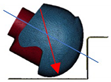
The impact test can be performed at four points of the helmet’s structure: frontal (B), side (X), top (P), and rear (R), as shown in Figure 1. The motorcycle helmet is placed on the headform and then fastened using the chin strap before installing the completed sample set in the testing machine. The impact test is then conducted by dropping the sample to impact with the anvil under an initial velocity of 7.5 m/s. The results are recorded for both acceleration and HIC at the CG of the headform. A commercial helmet will pass the criteria of the TIS 369-2557 regulation as long as the peak acceleration during the test and HIC do not exceed 275 g and 2400, respectively. TIS 369-2557 currently accepts only the test results to clarify the safety based on these criteria. Only a few sample helmets pass the standard’s requirements before being sold commercially in stores.
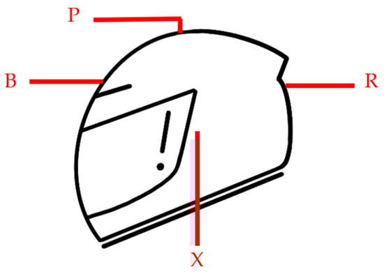
Figure 1.
Impact positions on the helmet structure.
The nomenclatures of B, X, P, and R in Figure 1 are only defined to indicate the positions of each impact point of the motorcycle helmet according to TIS 369-2557. These four positions will be investigated for a severe head injury based on the energy absorption ability under the impact test in Section 3.
3. Finite Element Model
A commercial motorcycle helmet from Thailand was used to analyze and investigate the structural performance under various impact severities compared with the test from TIS 369-2557, which was performed in this study. Accurate results from finite element analysis depend on the proper element types of the structure and material model. In this study, all components of the helmet’s structure were created based on a three-dimensional model using SolidWorks (version 2021 from Dassault Systèmes, Waltham, MA, USA) and imported for meshing in Hypermesh (version 2019 from Altair, Troy, MI, USA). The models were then assigned different material models in LS-DYNA (R111 from ANSYS, Inc., Washington County, PA, USA) before starting other pre-processing and analysis procedures. LS-DYNA is powerful software for performing dynamics analysis with a nonlinear explicit problem using the central difference method [37]. Furthermore, LS-DYNA also provides a variety of material models for simulation, which is suitable for a helmet structure that consists of different materials.
3.1. Motorcycle Helmet Structure
The open-face helmet model was divided into three parts: shell, foam, and comfort padding, as shown in Figure 2. All components were assigned as a deformable structure with the tetrahedral type of solid element, with only three degrees of freedom per node (only translational in three directions). The whole model of the helmet structure consisted of 33,113 nodes and 123,617 elements. AUTOMATIC_SINGLE_SURFACE was utilized to generate self-contact for each component of the helmet structure, in which the static and dynamic friction coefficients were 0.2 and 0.1, respectively. Furthermore, CONTACT_INTERIOR was also employed to prevent a negative volume of soft material (foam) under impact load, which always causes termination during analysis.
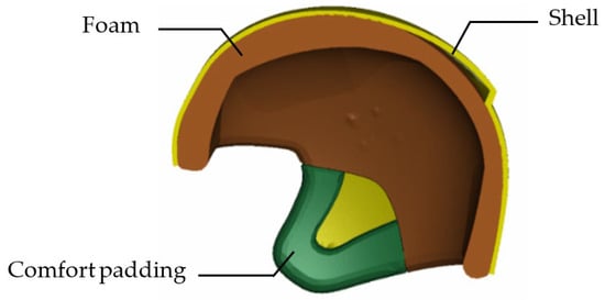
Figure 2.
Helmet structural model and its components.
A permanent deformation commonly occurs with any structure under assorted impact severities. Thus, the nonlinear material properties were essential to consider in the analysis procedure. The shell component was made from Acrylonitrile Butadiene Styrene (ABS), while the foam and comfort padding were made from EPS foam and Polystyrene (PU) foam, respectively. Tensile and compression tests were performed for determining the plastic properties of the shell and foam components, respectively. The mechanical properties for each component are displayed in Table 1 [38,39], while the nonlinear material behaviors of the shell and foam are illustrated in Figure 3. The material properties of the shell and foam component were directly determined by testing in this study, as displayed in Figure 3a,b, respectively. Since this work did not serve the test for comfort padding, the properties in Figure 3c were used and obtained from Bloodworth-Race et al. [38]. The total weight of the helmet structure was 1.02 kg, comprised of 0.89 kg from the shell, 0.098 kg from the foam, and 0.032 kg from the comport padding. In LS-DYNA, the material model of MAT_024_PIECEWISE_LINEAR_PLASTICITY was assigned for the shell component. Both the foam and comfort padding were utilized in the material model as MAT_063_CRUSHABLE_FOAM and MAT_057_LOWDENSITY_FOAM [40], respectively. The stress–strain relationship is necessary to be applied for all material models and components to recognize the nonlinear material behaviors during impact analyses.

Table 1.
Mechanical properties of each structural component.
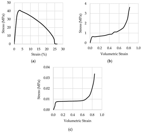
Figure 3.
Stress–strain curve of material models. (a) Shell; (b) foam; (c) comfort padding [38].
To apply the material properties in the LS-DYNA, coordinates of stress and plastic strain are commonly required to define nonlinear behaviors in MAT_024, while the relationship of stress and volumetric strain is assigned for foam properties.
3.2. Headform and Anvils
Since the headform and anvils can be ignored for the deformation and stress distribution during impact analysis, a rigid body is preferred to generate the finite element models. The headform was modeled to represent a motorcyclist’s head, while the anvils were used as the objects that impact the helmet structure. Both components were created based on specified dimensions according to TIS 369-2557 standards [11]. The M-size headform was selected in this paper because it was the most compatible with the helmet size (Figure 4) and had a weight of 5.6 kg. The material model of MAT_020_RIGID was utilized to assign these components in LS-DYNA. Finite element models of all rigid components were also generated using solid elements. The details for each structure are shown in Table 2.
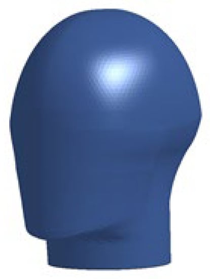
Figure 4.
CAD model of the headform.
Table 2.
Details of the finite element model of the headform and anvils.
Each component was separately discretized in the mesh for both rigid and deformable bodies. An assembly of all helmet components was then generated for model preparation before simulation. However, the motion constraints of a rigid body (translations and rotations) were defined in MAT_020, which was different from the deformable body in LS-DYNA.
4. Model Validation
An impact test with a flat anvil according to the TIS 369-2557 standard was performed for the validation procedure to compare with the simulation results. All components of the helmet structure were combined and set up as shown in Figure 5, in which the anvil was assigned as the fixed support. An initial velocity of 27 kph (7.5 m/s) was then applied downward for the other components. Since this paper needs to clarify the ability of comfort padding to reduce head injury during impact accidents, the model was divided into two cases: without comfort padding (Figure 5a) and with comfort padding (Figure 5b). Deformation behavior of a helmet can occur naturally when contact between the shell component and anvil is defined by AUTOMATIC_SURFACE_TO_SURFACE, which has a friction coefficient of 0.2. The analysis procedure was performed for 10 ms and the acceleration and HIC results were compared with the test and criteria of the standard.
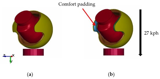
Figure 5.
Model configurations for impact simulation according to TIS 369-2557. (a) Without comfort padding; (b) with comfort padding.
Acceleration, which was recorded from the CG of the headform for all three cases (impact test according to TIS 369-2557 (Section 2.2), FE model with comfort padding, and FE model without comfort padding), is illustrated in Figure 6. The results from the test and FE models were recorded and compared based on the TIS 396-2557 criteria. The results were significantly different when the helmet caused the first impact with the anvil at 1 ms because the chin strap was neglected in the finite element model. The headform could fall and freely impact with the flat anvil under the assigned initial velocity more than the test and affect the CG of the headform to obtain the acceleration results. Peak acceleration occurred when the acceleration of the headform was transferred to the helmet’s structure until it caused the highest deformation. The results in Figure 6 display characteristics of finite element analysis that were similar to those of the test according to TIS 369-2557. Furthermore, the acceleration during the impact simulations clearly showed the same tendency as the test, which can confirm that the simulations had sufficiently accurate results to represent the test. The related results from the simulation (peak acceleration and HIC) in Figure 6 can be compared with the testing results in Table 3. The model without comfort padding achieved the highest performance to represent the helmet structure under impact conditions, which showed a maximum error of only 5.5% for HIC. However, the model with comfort padding achieved an unacceptable error of 17.1% for HIC, even when the peak acceleration was close to that of the test. Therefore, the finite element model without comfort padding could be employed to analyze other impact scenarios and investigate the damage to motorcyclists due to head injury. However, this commercial helmet in Thailand did not pass the TIS 369-2557 standard due to the testing and simulation results, with the HIC values being higher than the limit for this regulation, even though it has been sold commercially in stores.
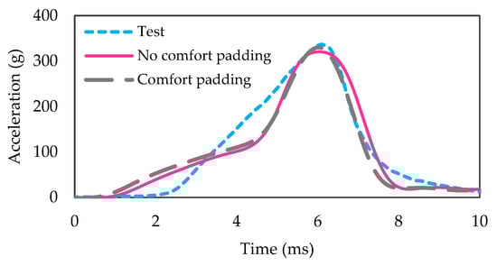
Figure 6.
Acceleration during impact test according to TIS 369-2557.
Table 3.
Comparisons of the results between the test and FE model.
Both helmet models, with and without comfort padding, were then analyzed to investigate the effect of comfort padding and head protective ability by impacting with a flat surface at four different positions (refer to Figure 1). The energy absorption, which was obtained from simulation, for all cases is compared in Figure 7, in which the comfort padding did not influence the reduction in head injury.
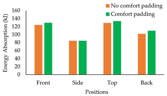
Figure 7.
Energy absorption with different positions under the impact test.
The comfort padding component is primarily responsible for enhancing the wearer’s comfort, rather than protecting against a head injury. The overall energy absorption was increased slightly from that of the helmet structural model with comfort padding. Therefore, these results emphasize that the helmet model without comfort padding was the most effective for further investigations concerning different kinds of impact accident cases. Therefore, the comfort padding can be neglected in the structural model for strength analysis and simulation.
5. Scenario of Impact Accidents
The efficacy of the finite element model for helmet structure was investigated for damage and head injury under three cases: sliding, collision with a footpath, and skidding to collide with a footpath. Cases of sliding and collision with a footpath directly represent an accident when colliding with an object or vehicle. The motorcyclist then falls to the road until the helmet and head impact the road surface or edge of the footpath. Skidding to collide with a footpath combines the effect of sliding until impact with the sharp edge of the footpath. Since a motorcycle accident causes falling behavior until impacting with an object that is similar to a projectile profile, both the head impact and velocity impact angles were employed to simplify the problem. The head impact angle (Figure 8a) defines the angle on a horizontal line of the headform to describe the impact direction from 0 to 90 degrees [30]. The impact velocity angle (Figure 8b) assigns the direction of the model to impact with the object along with normal and tangential velocities [32]. The head impact angle was specified as 30 degrees to analyze all cases, while the impact velocity angle was studied at 15, 30, 45, 60, and 75 degrees [31], as summarized in Table 4. Initial velocities of 27, 30, and 47 kph were applied to the model for all investigations, because 27 kph is the velocity specified according to TIS 369-2557 standard, while 30 and 47 kph are the average velocity and mean speed for lost control of motorcycles, respectively [32].
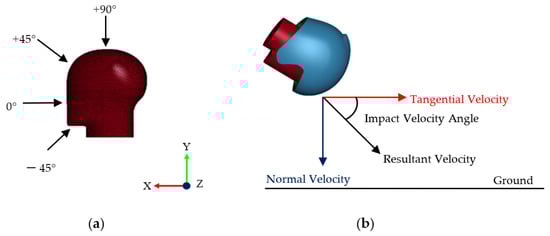
Figure 8.
Angles for assigning to the model. (a) Head impact; (b) impact velocity.
Table 4.
Directions of head impact and impact velocity.
5.1. Sliding Case (Case I)
The helmet model defined the boundary conditions for the sliding problem, as shown in Figure 9, which measures the height from the CG of the headform. The results of peak acceleration for all conditions from the simulation are displayed in Figure 10. It was found that both the impact angle and initial velocity significantly increased the peak acceleration, especially at the impact angles of 45, 60, and 75 degrees under the initial velocity of 47 kph. The lost control speed was the most dangerous for sliding with the ground due to the high acceleration of the headform at the impact angle of 30 degrees. The peak acceleration increased 8.4 times from 30 kph to 47 kph at the impact angle of 30 degrees. It caused severe damage to the motorcyclist’s head, even with no direct impact with any corner or sharp edge. If the initial velocity of 47 kph was neglected, the maximum peak acceleration of 1180 g occurred when the impact angle was 75 degrees at 30 kph. Furthermore, AIS 2+ was then calculated using Equation (2) based on the acceleration results, and found that the initial velocity of 47 kph caused 100% head injury probability for all impact angles, except for 15 degrees. The other velocities were quite safe in terms of severity and head injury due to the AIS 2+ being lower than 100%, except for impact angles of 60 degrees upwards.
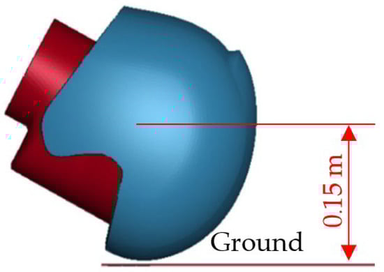
Figure 9.
FE model for the sliding case.
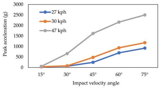
Figure 10.
Peak acceleration for each condition for the sliding case.
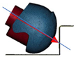
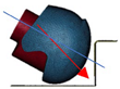
These serious impact angles (45, 60, and 75 degrees) had high acceleration by causing a large contact area at the shell. The helmet impacted the ground early and slid through the remaining surface longer than the others. Figure 11 compares the stress distribution at the initial velocity of 27 kph between impact angles of 30 and 60 degrees, which shows the broad area of stress at 60 degrees, causing severe damage to the helmet structure and headform. Energy absorption can be observed in the performance of each helmet component to reduce the head injury severity and prove protection. The low acceleration directly affected the foam component to reduce the head injury, which mainly absorbed all energy during impact accidents (Figure 12). The foam had poor protectability when the impact angle was 60 degrees upwards, absorbing less than 75%. The foam absorbed less than 75% of the impact energy, causing a high probability of severe head injury for the sliding case.
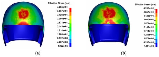
Figure 11.
Stress distribution on the shell component at 27 kph. (a) Impact angle: 30 degrees; (b) impact angle: 60 degrees.
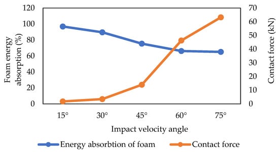
Figure 12.
Energy absorption and contact force from simulation at 27 kph for case I.
5.2. Collision with a Footpath (Case II)
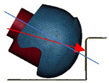
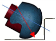
The helmet model was set to impact with the sharp edge of a footpath (Figure 13), with horizontal and vertical alignments of 1.5 m measured from the CG of the headform. The top and front areas of the helmet impacted with the corner simultaneously during the simulation; the stress distribution between impact angles of 45 and 60 degrees is compared in Figure 14. An impact angle of 45 degrees had a smooth distribution in both the front and top areas due to the broad contact surface, while 60 degrees seemed to cause point contact at the top surface. Low impact angles (15 and 30 degrees) were also found to have a point distribution of stress at the front area because the helmet behaved by sliding beforehand, so contact occurred at the top surface first. Thus, the smoothest distribution of stress occurred when the impact velocity angle was 45 degrees.
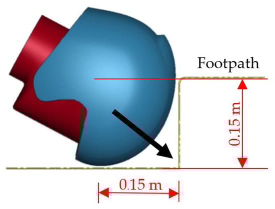
Figure 13.
FE model for collision with a footpath.

Figure 14.
Stress distribution upon impact with a footpath at 27 kph. (a) Impact angle: 45 degrees; (b) impact angle: 60 degrees.
The results of peak acceleration also emphasized that an impact velocity angle of 45 degrees was the best position for impact in this case because it showed the lowest value compared to other conditions (Figure 15). The lost control velocity (47 kph) also caused the highest severity of injury at the head during an impact accident, which was also neglected for further considerations. The maximum peak acceleration of 1310 g occurred when the impact angle was 15 degrees at 30 kph, because there was not enough surface for sliding, which caused deceleration before impacting with a sharp edge. The highest energy absorption of foam components was also around 80% at an impact angle of 45 degrees with the lowest contact force, while the energy absorption in other cases was lower than 75% (Figure 16). The injury probability at the head also indicated that only an impact angle of 45 degrees had severity less than 100% for collision with a footpath, except for an initial velocity of 60 kph. Thus, 75% energy absorption by foam is also an effective criterion to reduce the risk of head injury from impact with a sharp corner on a footpath.
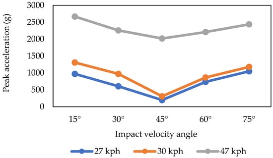
Figure 15.
Simulation results of peak acceleration in case II.
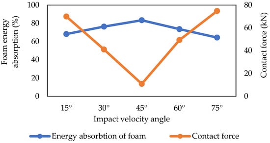
Figure 16.
Energy absorption and contact force from simulation at 27 kph in case II.
5.3. Skid to Collide with Footpath (Case III)
This case combined the characteristics of cases I and II to generate the finite element model (Figure 17), which had a length of 0.3 m for sliding. The height of CG for the headform was 0.15 m.
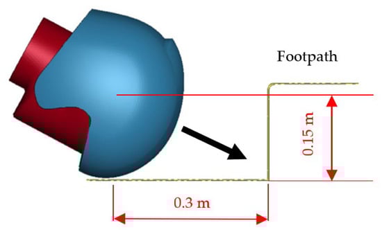
Figure 17.
FE model for skidding to collide with a footpath.
The results of peak acceleration for all initial velocities and impact velocity angles are illustrated in Figure 18, in which the lowest acceleration was present at an impact angle of 30 degrees. The effect of impact velocity at angles of 45, 60, and 75 degrees caused high acceleration because the front area of the helmet directly impacted the ground, and the whole model turned to collide with the sharp edge of the footpath. Part of the surface area of the helmet slid on the ground before impacting with the footpath at a 15-degree impact angle, which caused the peak acceleration to be higher than that at 30 degrees. Based on the peak acceleration results, the probability of head injury (AIS 2+) was lower than 100% only at initial velocities of 27 and 30 kph with impact angles of 30 and 45 degrees. The AIS 2+ for impact angles of 30 and 45 degrees at 27 kph were 7% and 44%, respectively, while the other cases, especially the initial velocity of 47 kph, had a probability of 100% according to AIS 2+.
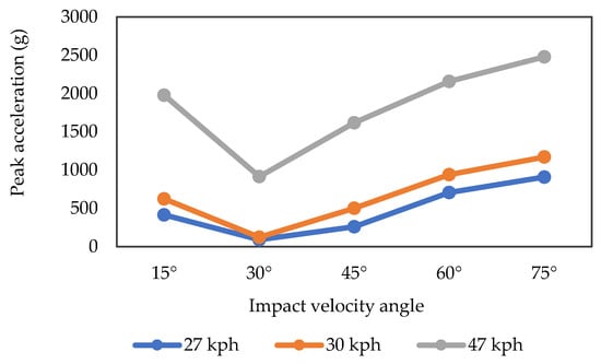
Figure 18.
Simulation results of peak acceleration of case III.
The contact force results comply with the peak acceleration, in which the impact angle of 30 degrees showed the lowest value when compared with the other impact angles (Figure 19). Furthermore, the foam component in the case of impact angles of 30 and 45 degrees absorbed almost 80% and 75% of the total impact energy, respectively. In contrast, the other impact conditions exhibited less than 75% energy absorption for foam. Thus, the foam component should perform energy absorption at over 75% to reduce the risk of head damage and injury severity according to AIS 2+.
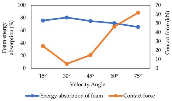
Figure 19.
Energy absorption and contact force from simulation at 27 kph for case III.
5.4. Result Comparisons
All studies examined the head protection performance of motorcycle helmet structures under three cases of accidents with different initial velocities and impact angles. The results in this section were calculated based on Equation (2) using the related results from finite element analysis. Firstly, the lost control speed (47 kph) caused the most severe head injury due to the high peak acceleration, and the probability of head injury for all cases was 100% according to AIS 2+ (Figure 20). The severity of injury was different for all three cases depending on the characteristics and behaviors in each case. An initial velocity of 27 kph at 30 and 45-degree impact angles seemed to be the most effective condition, because the probability of head injury was lower than 60% for all cases, except for 30 degrees in case II. The low impact angles caused an impact area at the top surface of the helmet only and increased the HIC because other surfaces had not absorbed the impact energy. The other impact angles varied based on each impact condition. Impact angles of 60 and 75 degrees also caused high peak acceleration for all cases, because the helmet had a collision with a footpath only, without sliding effects, and was not included for further comparison. However, the defined velocity for those helmet regulations (7.5 m/s or 27 kph) showed safe situations for head injury. In contrast, higher velocities (30 and 47 kph) were associated with more severe injuries, even though those speeds are typically used for driving nationwide.
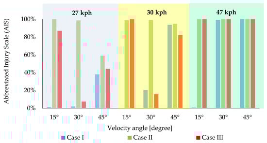
Figure 20.
Probability of head injury according to AIS 2+.
The energy absorption of foam components is also a pivotal point to evaluate in terms of the performance of helmet protectability during accidents. The results were compiled with the probability according to AIS 2+ (Figure 21). The highest energy absorption was observed when the impact angles were 30 and 45 degrees at an initial velocity of 27 kph. In all cases present, the foam absorbed over 75% of the energy, effectively reducing the impact of accidents’ head injury probability. Thus, the helmet structure should be designed by mainly considering the energy absorption of the foam component, which can enable the most efficient performance for head protectability and reduce the severity of head injury in the event of impact accidents.
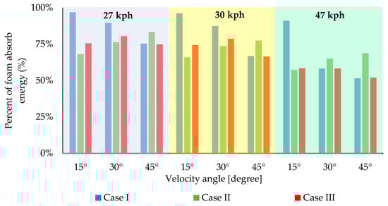
Figure 21.
Energy absorption of the foam component in all three cases.
6. Conclusions
This work proposes the critical points to investigate in terms of helmet structural performance for head protectability using a finite element model via LS-DYNA. The simulation results show that the helmet model represents the characteristics of the impact test well according to the TIS 369-2557 standard, and comfort padding had no significance in reducing head injury by evaluating energy absorption. The helmet structure was then analyzed under different initial velocities and impact conditions. The lost control speed (47 kph) presented the overall results of head injury for all cases, because the highest peak acceleration and probability of head injury was 100% according to AIS 2+. Impact angles also affected injury severity due to the characteristics of sliding and impacting in each case. The velocity impact angles of 30 and 45 degrees seemed safe compared with the others, since the high energy presences and head severities were less than 100% based on AIS 2+ criteria. Furthermore, foam was the most effective component in the helmet structure to reduce head injury by absorbing the impact energy. Head injury severity was less than 100% when the energy absorption of the foam was over 75% of the total energy. Thus, designing the foam component to absorb at least this much energy is recommended for an efficient motorcycle helmet that can reduce the risk of head injury and severity in impact accidents. The chin strap should be included in the model for investigating and examining the characteristics and behaviors of head injury and helmet structural performance in future work.
Author Contributions
Conceptualization, S.K.; methodology, S.K.; software, S.K. and T.N.; validation, S.K. and T.N.; formal analysis, S.K. and T.N.; writing—original draft preparation, S.K. and T.N.; writing—review and editing, S.K.; visualization, S.K.; supervision, H.H. All authors have read and agreed to the published version of the manuscript.
Funding
This research was supported the funding from the Mitsui Sumitomo Insurance Welfare Foundation (MSIWF) Research Grant 2021 and Research Grant for New Scholar 2021 with contract number RGNS 64-101 from the Office of the Permanent Secretary, Ministry of Higher Education, Science, Research, and Innovation.
Institutional Review Board Statement
Not applicable.
Informed Consent Statement
Informed consent was obtained from all subjects involved in the study.
Data Availability Statement
The data presented in this study are available within the article.
Acknowledgments
The authors gratefully acknowledge the financial support from the Mitsui Sumitomo Insurance Welfare Foundation (MSIWF) Research Grant 2021 and Research Grant for New Scholar 2021 with contract number RGNS 64-101 from the Office of the Permanent Secretary, Ministry of Higher Education, Science, Research, and Innovation.
Conflicts of Interest
The authors declare no conflict of interest.
References
- World Health Organization. Global Status Report on Road Safety 2018; World Health Organization: Paris, France, 2018. [Google Scholar]
- Aiello, M.; Galvanetto, U.; Iannucci, L. Numerical simulations of motorcycle helmet impact tests. Int. J. Crashworthiness 2007, 12, 1–7. [Google Scholar] [CrossRef]
- Afshari, A.; Rajaai, S.M. Finite Element simulations investigating the role of the helmet in reducing head injuries. Int. J. Simul. Model. 2008, 1, 42–51. [Google Scholar] [CrossRef]
- Tabary, M.; Ahmadi, S.; Amirzade-Iranaq, M.H.; Shojaei, M.; Asl, M.S.; Ghodsi, Z.; Azarhomayoun, A.; Ansari-Moghaddam, A.; Atlasi, R.; Rahimi-Movaghar, V.; et al. The effectiveness of different types of motorcycle helmets—A scoping review. Accid. Anal. Prev. 2021, 154, 106065. [Google Scholar] [CrossRef]
- Agrawal, V.; Kumrawat, R.; Sheikh, R.; Jain, S. Safety assessment of motorcycle helmet using finite element analysis. Int. J. Comput. Res. Dev. 2018, 3, 174–181. [Google Scholar]
- Tinard, V.; Deck, C.; Willinger, R. New methodology for improvement of helmet performances during impacts with regards to biomechanical criteria. Mater. Des. 2012, 37, 79–88. [Google Scholar] [CrossRef]
- Cernicchi, A.; Galvanetto, U.; Iannucci, L. Virtual modelling of safety helmets: Practical problems. Int. J. Crashworthiness 2008, 13, 451–467. [Google Scholar] [CrossRef]
- Gandhi, V.S.; Kumaravelan, R.; Ramesh, S.; Venkatesan, M.; Ponraj, M.R. Performance analysis of motor cycle helmet under static and dynamic loading. Mech. Mech. Eng. 2014, 18, 85–96. [Google Scholar]
- Department for Transportation. Federal Motor Vehicle Safety Standard (FMVSS) No. 218; Department for Transportation: Washington, DC, USA, 2015.
- Economic Commission for Europe. Uniform Provisions Concerning the Approval of Protective Helmets and of Their Visors for Drivers and Passengers of Motorcycles and Mopeds; Regulation No. 22 Revision 4; United Nations: Geneva, Switzerland, 2002. [Google Scholar]
- Thai Industrial Standard. Protective Helmets for Motorcycle Users; Ministry of Industrial (TIS): Bangkok, Thailand, 2014.
- Caserta, G.D.; Iannucci, L.; Galvanetto, U. Shock absorption performance of a motorbike helmet with honeycomb reinforced liner. Compos. Struct. 2011, 93, 2748–2759. [Google Scholar] [CrossRef]
- Gohel, G.; Bhudolia, S.K.; Elisetty, S.B.S.; Leong, K.F.; Gerard, P. Development and impact characterization of acrylic thermoplastic composite bicycle helmet shell with improved safety and performance. Compos. Part B 2021, 221, 109008. [Google Scholar] [CrossRef]
- Fernandes, F.A.O.; de Sousa, R.J.A.; Ptak, M.; Migueis, G. Helmet Design Based on the Optimization of Biocomposite Energy-Absorbing Liners under Multi-Impact Loading. Appl. Sci. 2019, 9, 735. [Google Scholar] [CrossRef] [Green Version]
- Liu, D.-S.; Chen, Y.-T. A finite element investigation into the impact performance of an open-face motorcycle helmet with ventilation slots. Appl. Sci. 2017, 7, 279. [Google Scholar] [CrossRef] [Green Version]
- Thai, T.Q.; Ly, H.A.; Vo, C.B.; Do, H.T.; Nguyen, P.T.L. Design and modeling motorcycle helmets using numerical simulation. AIP Conf. Proc. 2021, 2420, 020006. [Google Scholar]
- Fernandes, F.A.O.; de Sousa, R.J.A.; Ptak, M.; Wilhelm, J. Certified motorcycle helmets: Computational evaluation of the efficacy of standard requirements with finite element models. Math. Comput. Appl. 2020, 25, 12. [Google Scholar] [CrossRef] [Green Version]
- Chang, L.-T.; Chang, C.-H.; Chang, G.-L. Fit effect of motorcycle helmet—A finite element modeling. JSME Int. J. Ser. A Solid Mech. Mater. Eng. 2001, 44, 185–192. [Google Scholar] [CrossRef] [Green Version]
- Pinnoji, P.K.; Mahajan, P.; Bourdet, N.; Deck, C.; Willinger, R. Impact dynamics of metal foam shells for motorcycle helmets: Experiments & numerical modeling. Int. J. Impact Eng. 2010, 37, 274–284. [Google Scholar]
- De Sousa, R.A.; Gonçalves, D.; Coelho, R.; Teixeira-Dias, F. Assessing the effectiveness of a natural cellular material used as safety padding material in motorcycle helmets. Simulation 2012, 88, 580–591. [Google Scholar] [CrossRef]
- Totla, S.K.; Pillai, A.M.; Chetan, M.; Warad, C.; Vinodkumar, S.K.; Patil, A.Y.; Kotturshettar, B.B. Analysis of helmet with coconut shell as the outer layer. Mater. Today Proc. 2020, 32, 365–373. [Google Scholar] [CrossRef]
- Sakkampang, K.; Thinvovgpituk, C. The study on application of rubber sponges for impact absorber for motorcycle helmets. Int. J. Mech. Prod. Eng. 2020, 8, 52–57. [Google Scholar]
- Li, S.; Xiao, Z.; Zhang, Y.; Li, Q.M. Impact analysis of a honeycomb-filled motorcycle helmet based on coupled head-helmet modelling. Int. J. Mech. Sci. 2021, 199, 106406. [Google Scholar] [CrossRef]
- Kostopoulos, V.; Markopoulos, Y.P.; Giannopoulos, G.; Vlachos, D.E. Finite element analysis of impact damage response of composite motorcycle safety helmets. Compos. Part B Eng. 2002, 33, 99–107. [Google Scholar] [CrossRef]
- Ram, K.; Bajpai, P.K. FEM analysis of glass/epoxy composite based industrial safety helmet. IOP Conf. Ser. Mater. Sci. Eng. 2017, 225, 012174. [Google Scholar] [CrossRef] [Green Version]
- Meng, S.; Fahlstedt, M.; Halldin, P. The effect of impact velocity angle on helmeted head impact severity: A rationale for motorcycle helmet impact test design. In Proceedings of the 2018 International Research Council on the Biomechanics of Injury (IRCOBI 2018), Athens, Greece, 12–14 September 2018; IRCOBI: Athens, Greece, 2018; pp. 454–469. [Google Scholar]
- Mills, N.J.; Wilkes, S.; Derler, S.; Flisch, A. FEA of oblique impact tests on a motorcycle helmet. Int. J. Impact Eng. 2009, 36, 913–925. [Google Scholar] [CrossRef] [Green Version]
- Kholoosi, F.; Galehdari, S.A. Design and Analysis of a Helmet Equipped with Graded Honeycomb Structure Under Impact of Flat and Hemi-spherical Anvils. Procedia Eng. 2017, 173, 1299–1306. [Google Scholar] [CrossRef]
- Juste-Lorente, Ó.; Maza, M.; Piccand, M.; López-Valdés, F.J. The influence of headform/helmet friction on head impact biomechanics in oblique impacts at different tangential velocities. Appl. Sci. 2021, 11, 11318. [Google Scholar] [CrossRef]
- COST 327. Motorcycle Safety Helmets; European Co-Operation in the Field of Scientific and Technical Research: Luxembourg, 2001. [Google Scholar]
- Bourdet, N.; Deck, C.; Tinard, V.; Willinger, R. Behaviour of helmets during head impact in real accident cases of motorcyclists. Int. J. Crashworthiness 2012, 17, 51–61. [Google Scholar] [CrossRef]
- Meng, S.; Cernicchi, A.; Kleiven, S.; Halldin, P. High-speed helmeted head impacts in motorcycling: A computational study. Accid. Anal. Prev. 2020, 134, 105297. [Google Scholar] [CrossRef]
- Choma, E.F.; Evans, J.S.; Hammitt, J.K.; Gómez-Ibáñez, J.A.; Spengler, J.D. Assessing the health impacts of electric vehicles through air pollution in the United States. Environ. Interact. 2020, 144, 106015. [Google Scholar] [CrossRef]
- Moure-Guardiola, C.; Rubio, I.; Antona-Makoshi, J.; Olmedo, Á.; Loya, J.A.; Rodríguez-Millán, M. Evaluation of Combat Helmet Behavior under Blunt Impact. Appl. Sci. 2020, 10, 8470. [Google Scholar] [CrossRef]
- Association for the Advancement of Automotive Medicine. Abbreviated Injury Scale: 2015 Revision, 6th ed.; Association for the Advancement of Automotive Medicine: Chicago, IL, USA, 2018. [Google Scholar]
- Wong, E. Abbreviated Injury Scale. In Encyclopedia of Clinical Neuropsychology; Kreutzer, J.S., DeLuca, J., Caplan, B., Eds.; Springer: New York, NY, USA, 2011; pp. 5–6. [Google Scholar]
- Liu, Y. ANSYS and LS-DYNA used for structural analysis. Int. J. Comput. Aided Eng. Technol. 2008, 1, 31–44. [Google Scholar] [CrossRef]
- Bloodworth-Race, S.; Critchley, R.; Hazael, R.; Peare, A.; Temple, T. Testing the blast response of foam inserts for helmets. Heliyon 2021, 7, e06990. [Google Scholar] [CrossRef]
- Sanborn, B.; Song, B. Poisson’s ratio of a hyperelastic foam under quasi-static and dynamic loading. Int. J. Impact Eng. 2019, 123, 48–55. [Google Scholar] [CrossRef]
- Ozturk, U.E.; Anlas, G. Finite element analysis of expanded polystyrene foam under multiple compressive loading and unloading. Mater. Des. 2011, 32, 773–780. [Google Scholar] [CrossRef]
Publisher’s Note: MDPI stays neutral with regard to jurisdictional claims in published maps and institutional affiliations. |
© 2022 by the authors. Licensee MDPI, Basel, Switzerland. This article is an open access article distributed under the terms and conditions of the Creative Commons Attribution (CC BY) license (https://creativecommons.org/licenses/by/4.0/).