
Diagnosing the Machine Set Rotor Using Its Relative Vibrations


Abstract
1. Introduction
2. Machine Set Rotor, Vibration and Mechanical Efficiency of the Machine Set Rotor
- machine diagnosing is part of machine maintenance; and
- the relative vibrations of the machine rotor contain diagnostically useful information.
- In these working states, the driven machine can be in the working mode MU > 0 or run idle, without a load, MU = 0. For a constant average angular speed, the value of the components of Equation (6) with respect to time can be considered as periodic signals, and each of them can be presented as the sum of harmonic signals with specific values of the harmonic order, amplitude and phase angle. It is possible to determine the reference spectrum of the driving moment and effective moment. Additionally, the reference spectrum of the friction moment can be determined. It can be assumed that for a given machine set rotor and for a specific average rotary speed, there exists a model of value as a function of the rotation angle and a spectrum model of the angular acceleration . Comparing the real value as a function of the rotating angle or real spectrum with their respective models, we can draw conclusions on the changes in the moments of a machine set.
3. Qualities and Symptoms of the Wear Margin of the Machine Set Rotor
3.1. Quality of the Machine Set Rotor Wear Margin
- the shaft line axis of the machine set rotor will be a straight line;
- centers of the masses of the machine set rotor will overlap with the rotation axis of the machine set rotor;
- the rotor discs will be permanently connected with the shaft, and the masses and moments of inertia of the rotor discs and the shaft rigidity will conform with the specification.
- rotor components (shafts and discs, including coupling discs) of the machine set will not have errors of shape and position;
- there will be no coaxiality errors of holes for bearings, errors of shape and hole dimensions, errors of shape and dimensions of shells and rolling bearings;
- support bearings will have oil film of proper thickness.
- (a)
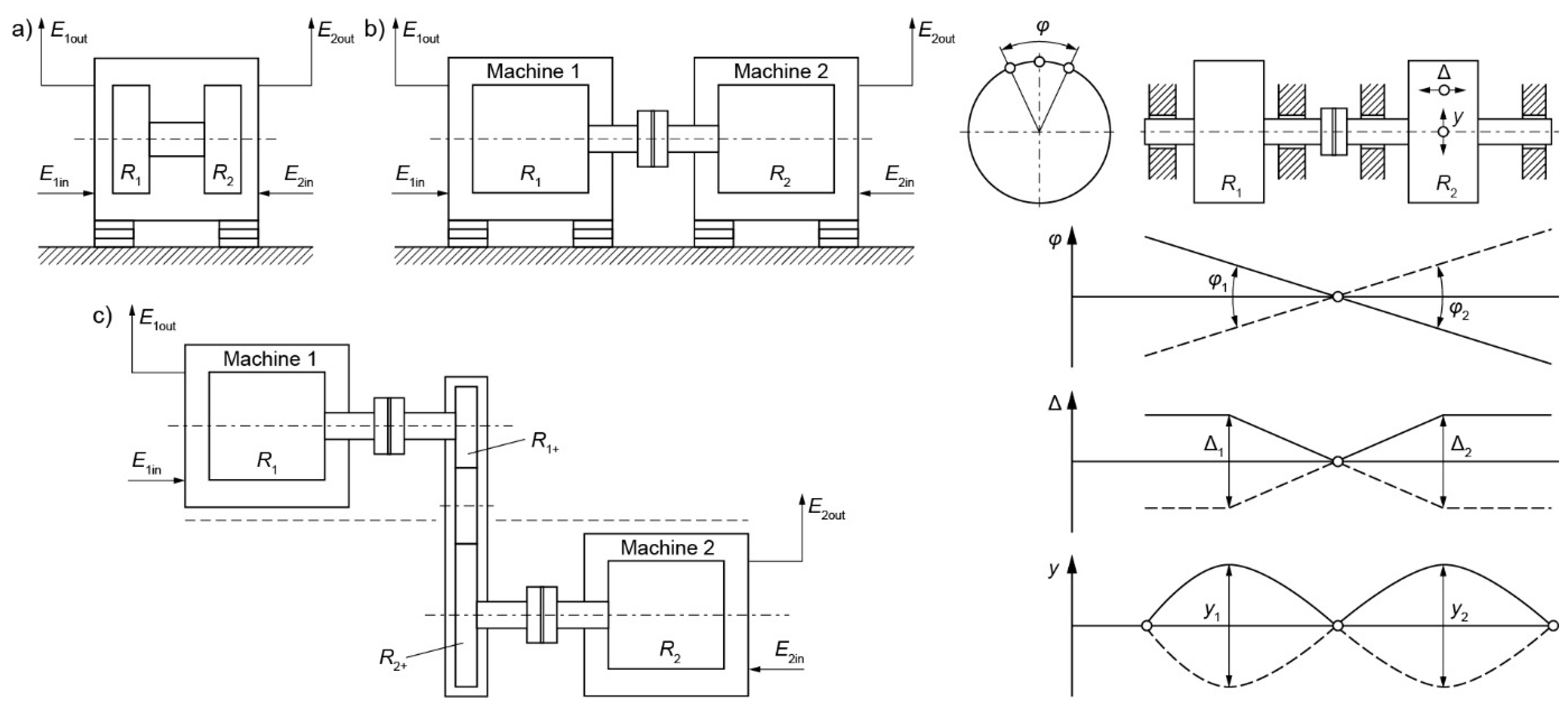
- alignment errors—a typical alignment error leads to a constant (non-rotating) bending line of the shaft centerline [27]. Journals are displaced, particularly the first journals on the coupling side, mainly slide bearings (displacement within the bearing clearance). These deviations, referred to as angular offset and parallel offset, are measurable on the disconnected shafts of the machine set rotor.
- (b)
- displacement of the shaft bearing support of one of the machines. The displacement of bearing support may be caused by deformations of the support, machine body or foundation. Deformations of machine foundations are specific for a given production system and, in many cases, are given in the system specification. For instance, deformed foundation can be due to deformations of the ship’s hull [19]. The causes of support displacement are described in Ref. [28].
3.2. Qualities and Symptoms of the Wear Margin of Machine Rotor Slide Bearings
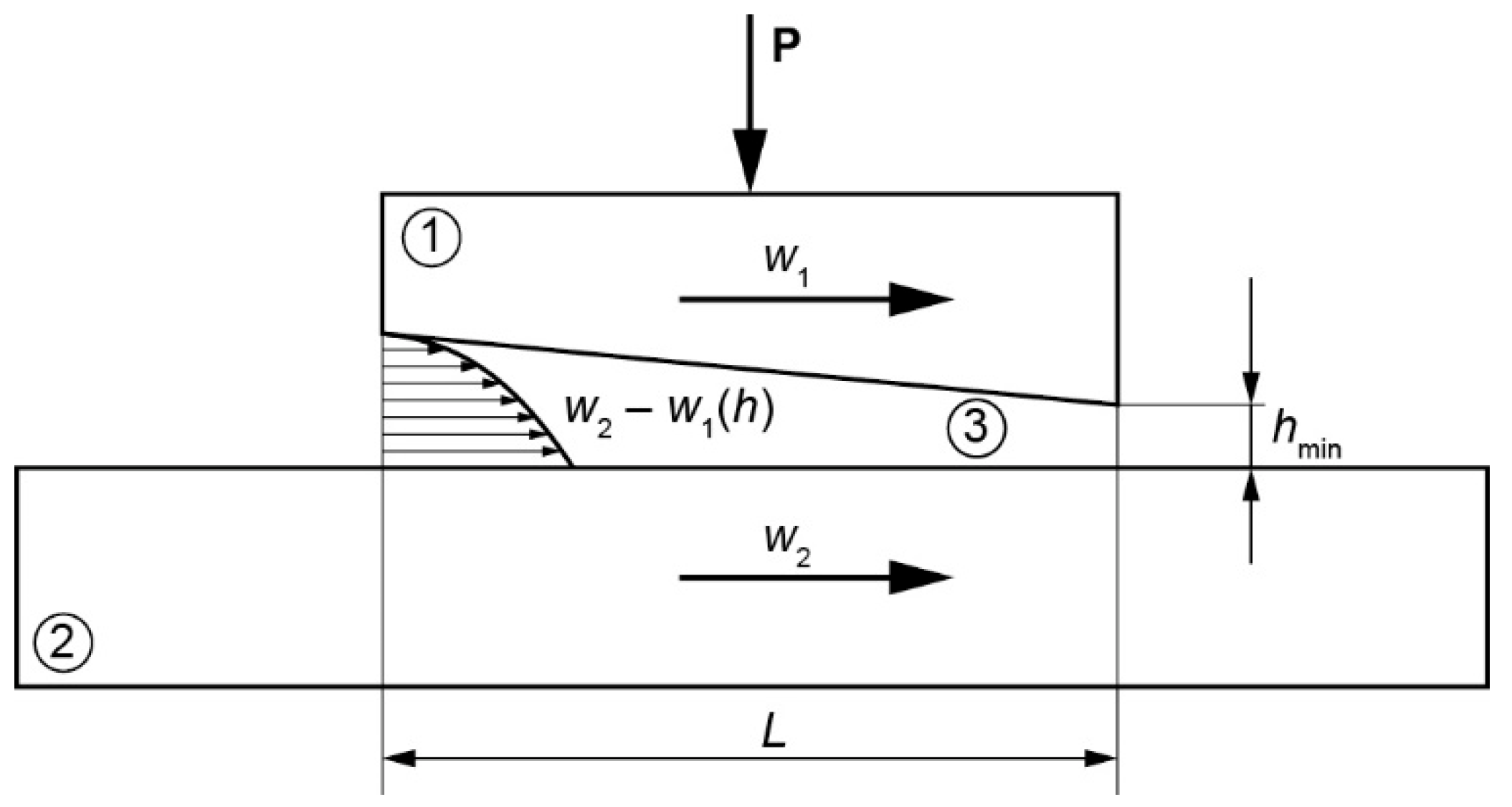
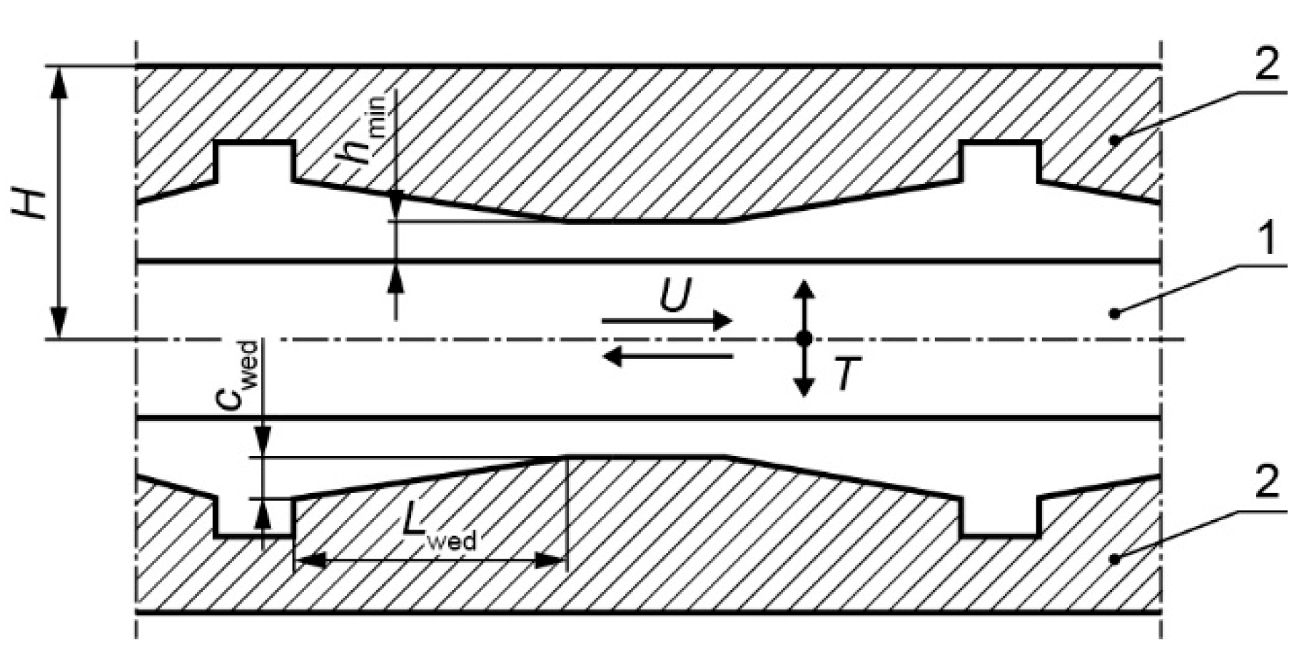
- for a bearing with 100% wear margin, the value of Bk complies with the specification and Bk = Bk1, whereas the measured values of the H symptom are H = H1, H0 = H01, respectively;
- if H = H2, H0 = H02, then for (H2 − H02)/Cwed from the standard Bk = Bk2 ≠ Bk1. The change in the value of Bk can be attributable to a change in the value of one or more quantities of which Bk is composed (12);
- if H0 = H2 < H01, one of the causes is wear resulting in a change in the length of the gap L = ΣLwed. If the change in the gap length is the only cause for the change in the value of Bk, then L2 = 1·(H2 − H02)2/(η1·U1·Bk2).
- for a bearing with 100% wear margin, the value of So complies with the specification and So = So1, whereas the measured value of the symptom e = e1 for clearance C = C1;
- for a non-operational bearing with the journal in contact with the bearing shell, e = e0 = C/2: e01 = C1, e02 = C2;
- if the measured e = e2 < e1, the wear margin is less than 100%. So = So2 ≠ So1, calculated using the standard for ε = ε2 = e2/(C2/2). The change in So can be caused by the So constituents other than the clearance (14).
3.3. Symptoms of Misalignment of the Machine Set Rotor with a Crankshaft
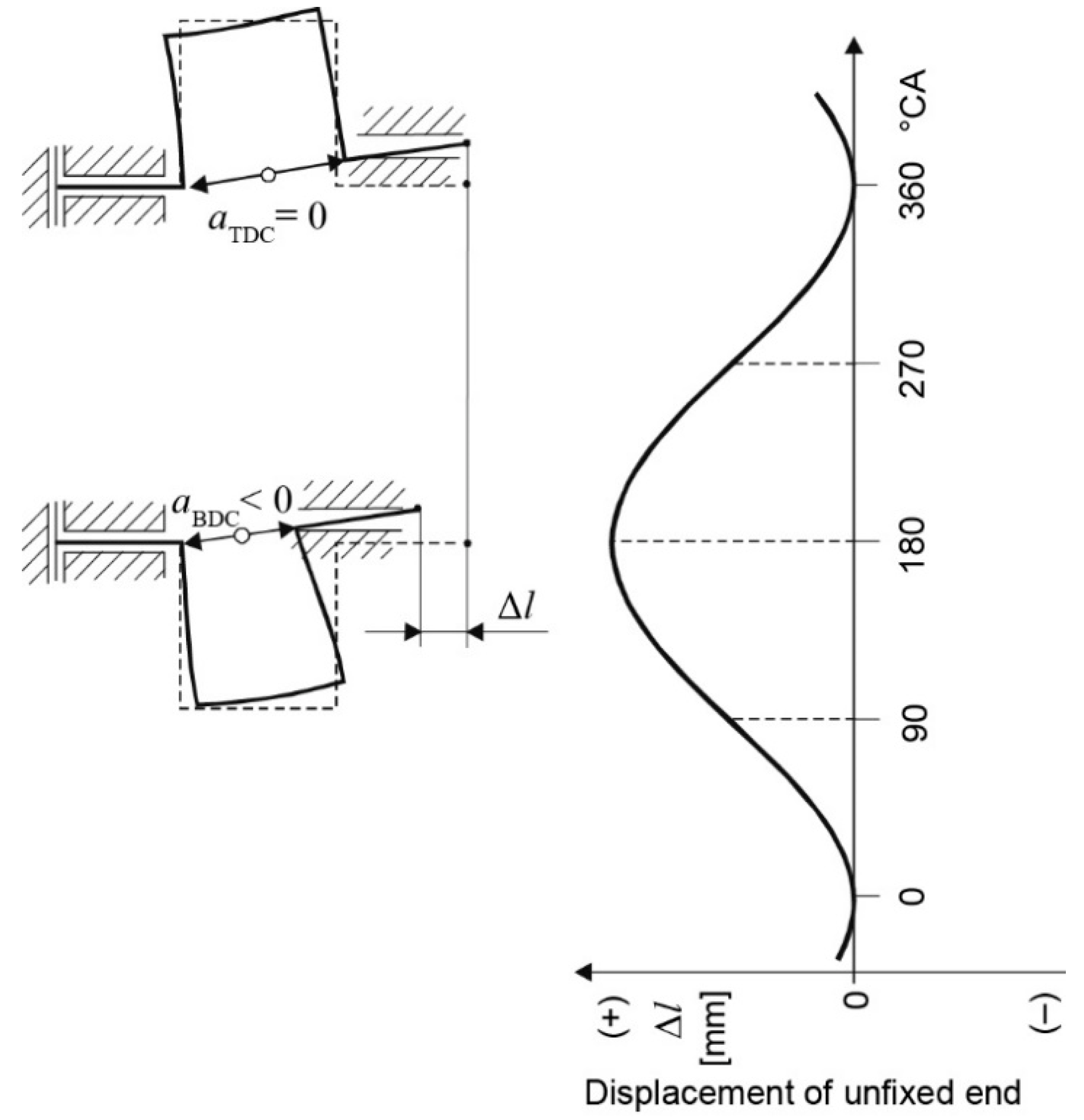
- vertical plane Δav = aTDC − aBDC (TDC—top dead center, BDC—bottom dead center);
- horizontal plane Δah = aSB − aPS (SB—starboard side, PS—port side).
3.4. Qualities and Symptoms of the Wear Margin of the Machine Set Rotor with a Crankshaft
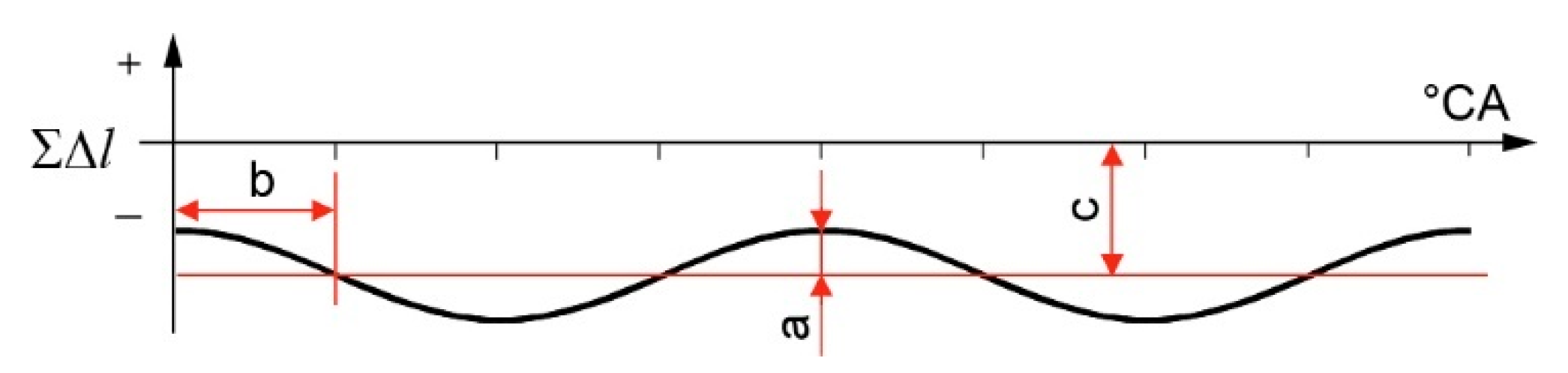
- if the load is identical and constant on all cranks, the average value, amplitude and phase shift of the axial vibrations of the free end of the crankshaft Δlf.e(α) depend on the alignment of the machine set rotor;
- the values of e(α) and ΔH(α) make it possible to identify the cause of the alignment change. An increase in the eccentricity e in the flywheel bearing indicates non-coaxiality of the set’s shafts or wear of the bearing. Changes in the values of ΔH indicate the effect of axial forces from another machine. Where e and ΔH remain constant, a change in the value of vibrations of the shaft free end Δlf.e(α) indicates deformations of the support or wear of the bearings supporting the crankshaft.
4. Measurements of Relative Vibration
- measurements of other types of vibration and correction of the results or;
- measurement of a given type of vibration by more than one sensor and mathematical operations on the measured signals or;
- fixing the reference plane with the rotor axis; the reference plane performs the same motions as the rotor, except for the measured motion.
4.1. Measurements of Torsional Vibration Relative Acceleration of Machine Set Rotors
4.2. Measurements of the Displacement of Rotors’ Relative Vibration
- a sufficiently large linear range of the distance-voltage characteristic;
- vibrating element can be made of any electric conductor material, which allows the measurement of vibration without installing additional elements on the rotor.
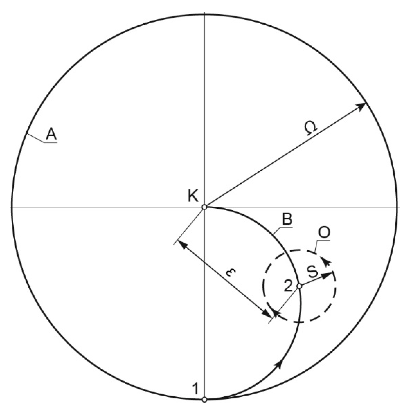
4.2.1. Measurements of Journal Eccentricity in the Shell
- eddy current sensors can be placed in the holder and mounted to the machine body. The sensors in the holder form a measuring head. The sensor axes in the head should be perpendicular to the axis/to the generatrixes of the journal;
- the head on the machine body must be mounted so that the sensor axes intersect with the axis of the shell hole in the machine body;
- the measurement plane should be in a place where the journal is not subject to wear;
- the measuring head must be calibrated, i.e., a specific value of the displacement (displacement signal) measured by the head for the journal located in the center of the shell hole must be specified.
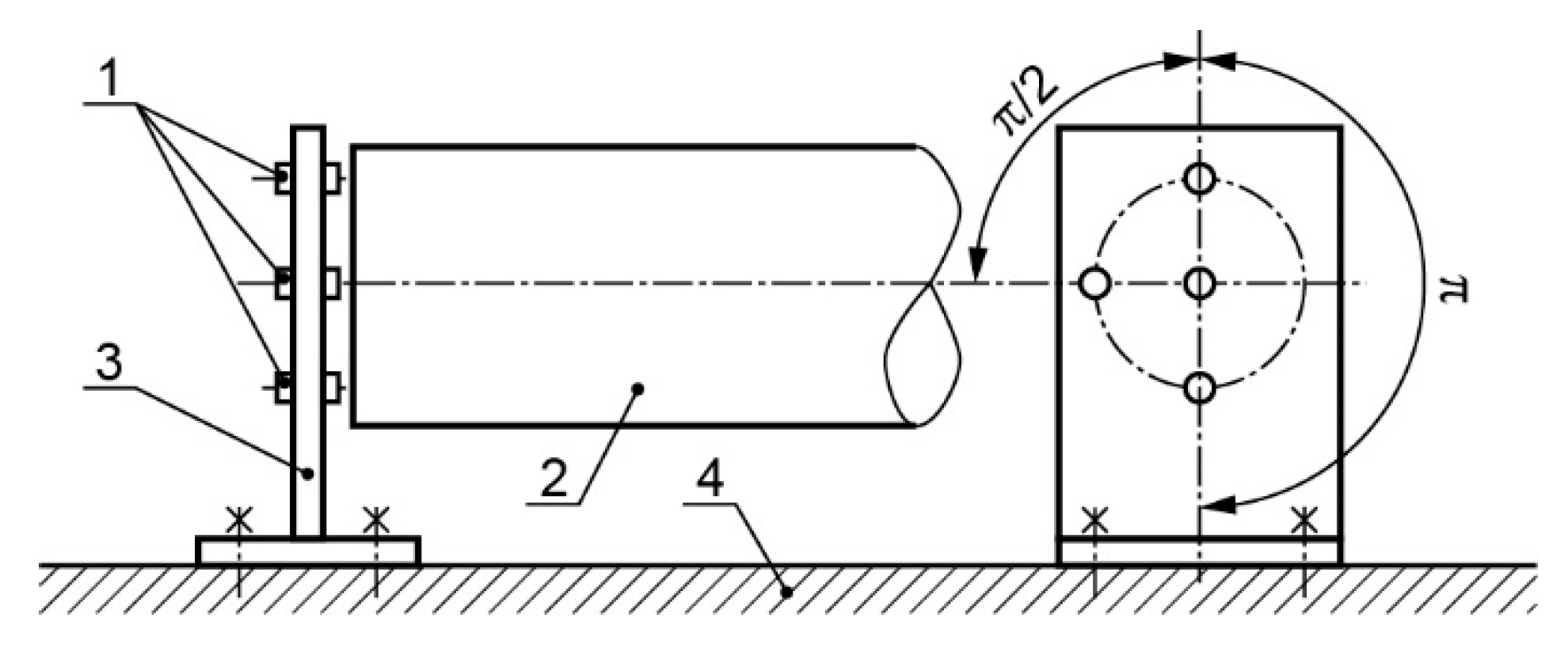
4.2.2. Measurements of the Displacement of Relative Axial Vibration
- one sensor located on the shaft axis; sensor axis is aligned with the rotor shaft axis;
- two sensors with the axes set parallel to the rotor shaft axis, and the same distance of both sensor axes to the shaft axis. The sensors can be mounted circumferentially:
- shifted by π/2,
- shifted by π.
- face of the rotor shaft free end;
- face of the flange made together with the rotor shaft;
- end face of the flywheel or the face of a special disc mounted on the shaft, etc.
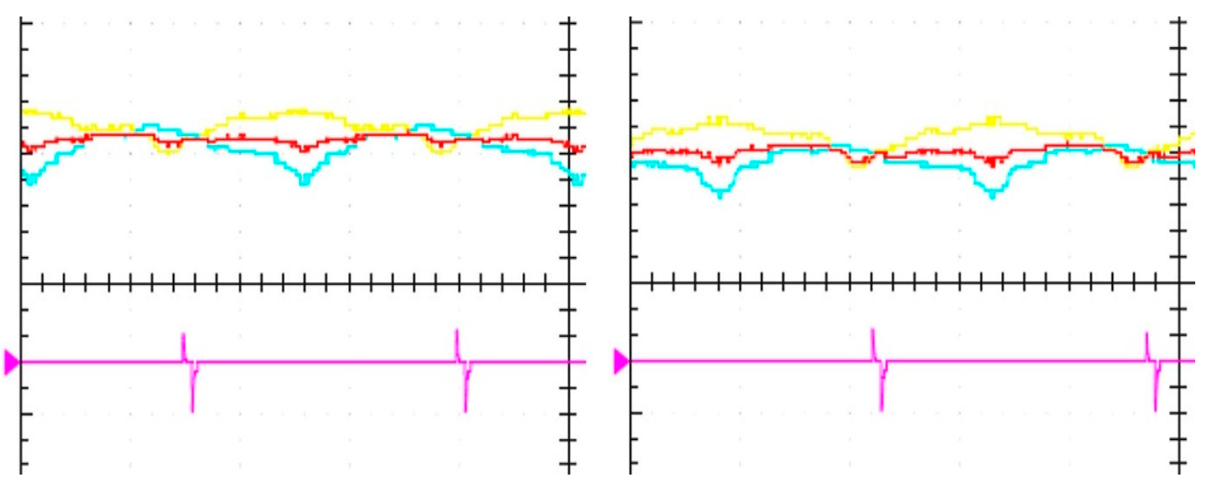
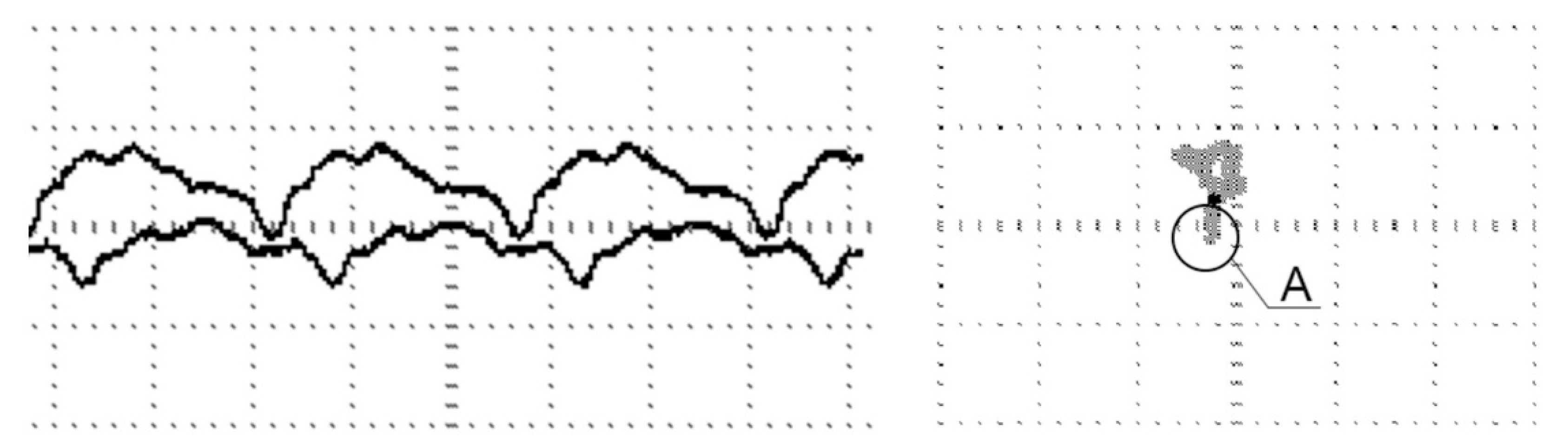
- both time waveforms should be identical, have the same average values and should not have a phase shift (φ = 0);
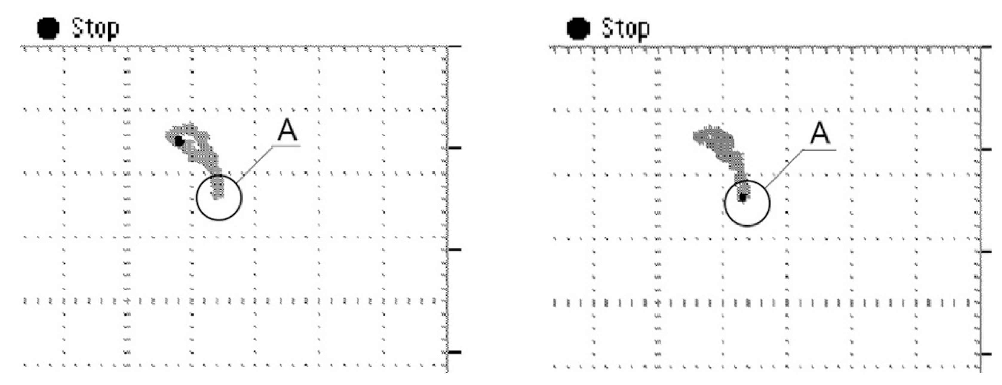
- in the XY system, the image should be a straight section corresponding to the Lissajous curve for φ = 0 (Table 2).
- vibration dependent on the rotor alignment (values of cranks deflection);
- vibration as the result of rotor displacement in the axial bearing clearance.
5. The Position Head of Marine Engine Crankshaft
- affects the axial vibration of the crankshaft free end;
- depends on the alignment of the machine set rotor.
6. The Arrangement of Sensor Heads for Vibration Diagnostics of Marine Propulsion System Rotors
7. Discussion
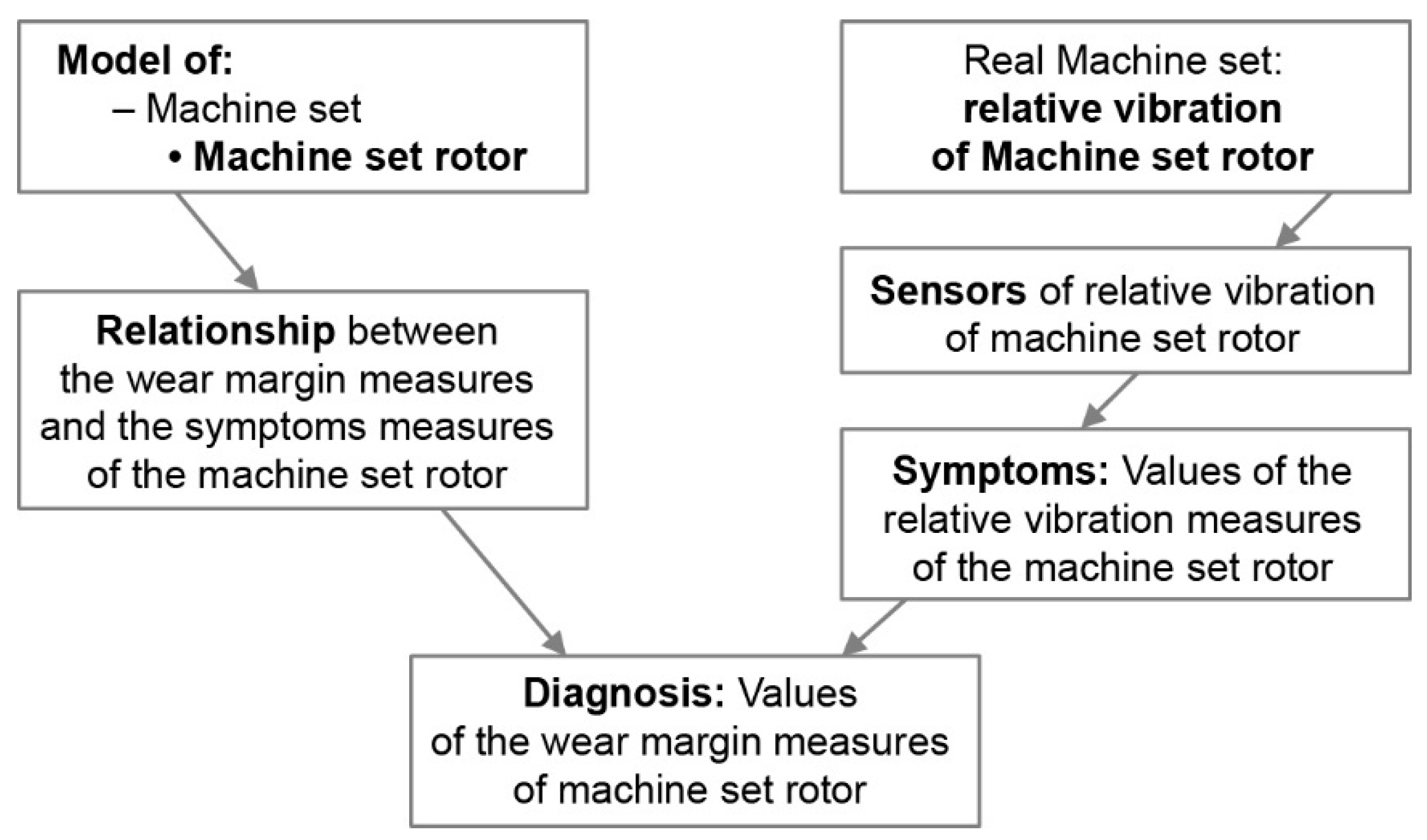
- the machine set is considered,
- the machine set rotor is distinguished as a functional unit,
- the physical models of the relationship between the wear margin measures and the symptoms measures of the machine set rotor are built.
8. Conclusions
- From the point of view of maintenance, it is justified and technically possible to distinguish the “machine set rotor” as a functional unit in the driving machine–driven machine set found in production and propulsion systems. It is possible to create the model of a machine set rotor.
- Friction moment can be considered as one of the substitute wear margin measures of the machine set. Changes in the friction moment result in measurable changes in the rotor torsional vibration acceleration.
- It is possible to identify (substitute) wear margin qualities in the driving machine–driven machine set. The qualities describing the wear margin of the machine set rotor should include alignment, unbalance and transfer function of the machine set rotor. In a machine set rotor supported by slide bearings, the machine set rotor alignment and unbalance have an impact on the value of the position of the journal relative to the shell in the case of radial bearings and the position of the shaft flange relative to the axial bearing shell. The position of the journal and the position of the flange relative to the corresponding shells also depend on the wear margin of the given bearing, which means that the wear margin of the bearings affects the alignment of the machine set rotor. If the machine set rotor has a crankshaft, the deflection of shaft cranks is a measure of crank alignment. The deflection of cranks causes axial displacement of the crankshaft end frontal surface during the rotation. The (substitute) wear margin measures of the machine set rotor can change in the measure of journal or flange position relative to the corresponding shells and measures of cranks deflection or measure of axial displacement of crankshaft free end.
- It is possible to identify the (substitute) wear margin measure of the radial and axial slide bearing. They are (for the radial slide bearings) the dimensionless Sommerfeld number and (for axial slide bearings) the bearing load capacity (the number Bk). For radial bearings—the eccentricity of the journal in the shell, while for axial bearings—the distance between the shell and the flange can be used as wear margin symptoms.
- During the machine set operation, changes in the crank deflection cause measurable changes in the axial vibration of the free end of the crankshaft. Changes in the eccentricity of the radial bearing cause measurable changes in the radial rotor vibration measure, and changes in the distance in axial bearing result in measurable changes in the axial rotor vibration measure.
- The desired measures of axial vibration of the free crankshaft end are an average value, amplitude and phase shift of the displacement waveform. Because the average value of the displacement of the free end is affected by the displacement of the whole rotor within the axial bearing clearance, simultaneous measurement of the average value of axial displacements in the axial bearing is required.
- The radial vibration in radial bearing can be measured as the trajectory of the journal center. The desired measures of radial rotor vibration are a distance between the average value of the journal center trajectory and the center of the hole for the bearing shell. The distance can by measured by means of a calibrated sensor head.
- The desired measures of rotor axial vibration are an average value of the rotor vibration displacement measured in the thrust or the position bearing by means of a calibrated sensor head.
- For a machine set rotor with crankshaft supported by slide bearings, it is justified and possible to build a position head of the machine set rotor and to find a method of position head calibration.
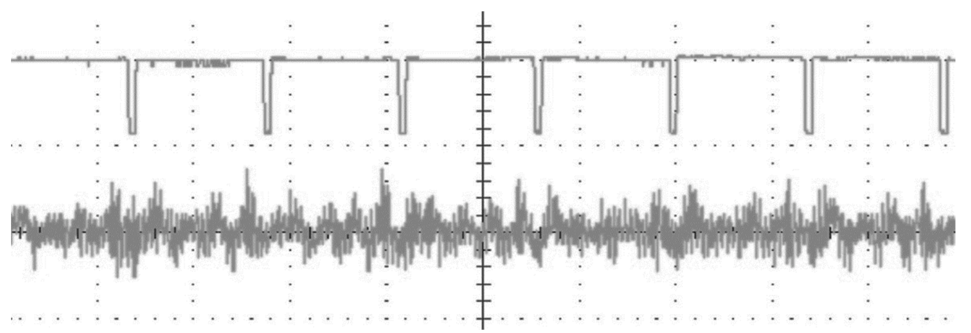
- Free crankshaft end head, i.e., the free end head with a Ferraris sensor, displacement sensor and shaft angle sensor with a converter can be used to measure the synchronously averaged waveform and spectrum of the machine set rotor torsional vibration acceleration and axial vibration displacement.
- The arrangement of the free crankshaft end head, rotor position head and sleeve bearing head should be considered as part of the new diagnostic system for identifying probable causes of wear margin loss of the machine set rotor regarded as a functional unit of the ship’s propulsion system.
Funding
Institutional Review Board Statement
Informed Consent Statement
Data Availability Statement
Conflicts of Interest
References
- Trianni, A.; Cagno, E.; Bertolotti, M.; Thollander, P.; Andersson, E. Energy management: A practice-based assessment model. Appl. Energy 2019, 235, 1614–1636. [Google Scholar] [CrossRef]
- Shang, Z.; Gao, D.; Jiang, Z.; Lu, Y. Towards less energy intensive heavy-duty machine tools: Power consumption characteristics and energy-saving strategies. Energy 2019, 178, 263–276. [Google Scholar] [CrossRef]
- Timashev, S.; Bushinskaya, A. Diagnostics and Reliability of Pipeline Systems; Springer: Cham, Switzerland, 2016. [Google Scholar]
- Vijayalakshmia, S.; Karthikhab, R.; Paramasivamc, A.; Bhaskar, K.B. Condition Monitoring of Industrial Motors using Machine Learning Classifiers. In Proceedings of the International Conference on IoT based Control Networks and Intelligent Systems (ICICNIS 2020), Kerala, India, 10–11 December 2020. [Google Scholar]
- Jin Guo, J.; Liu, Y.; Li, K.; Liu, Q. Research on an ID-PCA Early Fault Detection Method for Rolling Bearings. Appl. Sci. 2022, 12, 4267. [Google Scholar]
- Del Buono, F.; Calabrese, F.; Baraldi, A.; Paganelli, M.; Guerra, F. Novelty Detection with Autoencoders for System Health Monitoring in Industrial Environments. Appl. Sci. 2022, 12, 4931. [Google Scholar] [CrossRef]
- ISO 17359:2018; Condition Monitoring and Diagnostics of Machines—General Guidelines. International Organization for Standardization: Geneva, Switzerland, 2018; p. 1.
- ISO 7919-1:1996(en); Mechanical Vibration of Non-Reciprocating Machines—Measurements on Rotating Shafts and Evaluation Criteria—Part 1: General Guidelines. International Organization for Standardization: Geneva, Switzerland, 1996.
- ISO10816-1:1995/Amd.1:2009(en); Mechanical Vibration—Evaluation of Machine Vibration by Measurements on Non-Rotating Parts—Part 1: General Guidelines Amendment 1. International Organization for Standardization: Geneva, Switzerland, 2009.
- Bielawski, P. Miary i wartości graniczne potencjału eksploatacyjnego maszyn systemów produkcyjnych/Measures and limits of machine wear margin of production systems. Probl. Eksploat. Maint. Probl. 2016, 1, 129–159. [Google Scholar]
- Bielawski, P. Identification of the Wear Margin of a Pipeline—Machine Subsystem. Appl. Sci. 2020, 10, 3977. [Google Scholar] [CrossRef]
- Fehrenbach, H.; Quante, F.; Besserdich, G. Diagnosis of Combustion Engines by the Analysis of the Crankshaft’s Rorational Speed. VDI Ber. 1987, 644, 73–80. [Google Scholar]
- Biezeno, C.B.; Grammel, R. Technische Dynamik; Band 2; Springer: Berlin/Heidelberg, Germany; New York, NY, USA, 1953. [Google Scholar]
- Trybuła, W. Ocena Stanu Technicznego Silnika Spalinowego Metodą Przyspieszeń. Diagnostyka Pojazdów; Ossolineum: Wrocław, Poland, 1981; pp. 75–92. [Google Scholar]
- Arkuszewski, A.; Wdowiak, W. Wpływ Niedomagań Silnika z Zapłonem Samoczynnym na Charakterystykę Bezwładnościową—Źródło Informacji Diagnostycznych. Ph.D. Thesis, Politechnika Poznańska, Poznań, Poland, 1983. [Google Scholar]
- Jankowski, M.; Żółtowski, B. Komputerowa kontrola efektywności pracy silnika spalinowego metodą przyspieszeń. Zagadnienia Eksploat. Masz. 1993, 4, 541–551. [Google Scholar]
- Piętek, A. Charakterystyki Dynamiczne Silników o Zapłonie Samoczynnym i Ich Aplikacje Diagnostyczne; WAT: Warszawa, Poland, 1997. [Google Scholar]
- Wang, A.; Luo, Z. Performance Degradation Research of Combined Rotor Considering Rod Relaxation. In Proceedings of the 3rd International Conference on Materials Engineering, Manufacturing Technology and Control (ICMEMTC 2016), Taiyuan, China, 27–28 February 2016; pp. 911–917. [Google Scholar]
- Murawski, L. Shaft line alignment analysis taking ship construction flexibility and deformations into consideration. Mar. Struct. 2005, 18, 62–84. [Google Scholar] [CrossRef]
- ISO 1940-1; Mechanical Vibration—Balance Quality Requirements for Rotor in a Constant (Rigid) State, Part 1: Specification and Verification of Balance Tolerances. International Organization for Standardization: Geneva, Switzerland, 2003.
- Uhl, T.; Lisowski, W. Praktyczne Problemy Analizy Modalnej Konstrukcji; AGH: Kraków, Poland, 1996. [Google Scholar]
- Kolerus, J.; Wassermann, J. Zustandsüberwachung von Maschinen; Expert Verlag: Renningen, Germany, 2008. [Google Scholar]
- Klein, U. Schwingungsdiagnostische Beurteilung von Maschinen und Anlagen; Verlag Stahleisen GmbH: Düsseldorf, Germany, 2000. [Google Scholar]
- Goldman, S. Vibration Spectrum Analysis: A Practical Approach; Industrial Press Inc.: New York, NY, USA, 1999. [Google Scholar]
- Nowikow, M.P. Podstawy Technologii Montażu Maszyn I Mechanizmów; WNT: Warszawa, Poland, 1972. [Google Scholar]
- Bielawski, P. Identyfikacja Obiektów Technicznych Systemów Produkcyjnych; Akademia Morska w Szczecinie: Szczecin, Poland, 2014. [Google Scholar]
- Machine Diagnosis, Field Balancing, Shaft Alignment: Methods, Benefits and Solutions; Seminar C44; Carl Schenck AG: Darmstadt, Germany, 1995.
- Morel, J. Drgania Maszyn I Diagnostyka Ich Stanu Technicznego; Wyd. Polskie Towarzystwo Diagnostyki Technicznej: Warszawa, Poland, 1992. [Google Scholar]
- Wӓrtsilӓ 64 Instruction Manual; Wӓrtsilӓ NSD Italia S.p.A.: Trieste, Italy, 1999.
- Meier-Peter, H. Das Ausrichten von Schiffswellenleitungen. Hansa 1985, 4, 351–353. [Google Scholar]
- Zhang, Y.; Biboulet, N.; Venner, C.H.; Lubrecht, A.A. Prediction of the Stribeck Curve under full-film Elastohydrodynamic Lubrication. Tribol. Int. 2020, 149, 105569. [Google Scholar] [CrossRef]
- Böswirth, L.; Bschorer, S. Technische Strömungslehre; Vieweg + Teubner Verlag: Wiesbaden, Germany, 2012. [Google Scholar]
- Neale, M.J. The Tribology Handbook; Butterworth-Heinemann: Oxford, UK, 1995. [Google Scholar]
- Hebda, M.; Wachal, A. Trybologia; WNT: Warszawa, Poland, 1980. [Google Scholar]
- Krzemiński-Freda, H. Łożyska Toczne; PWN: Warszawa, Poland, 1985. [Google Scholar]
- Barwell, F.T. Łożyskowanie; WNT: Warszawa, Poland, 1984. [Google Scholar]
- VDI 2204; Verein Deutscher Ingenieure. Verein Deutscher Ingenieure: Düsseldorf, Germany, 1992.
- Spiegel, K.; Fricke, J. Bemessungs-und Gestaltungsregeln für Gleitlager: Herkunft-Bedeutung-Grundlagen-Fortschritt. Tribol. Schmier. 2000, 47, 32–41. [Google Scholar]
- Spiegel, K.; Fricke, J. Bemessungs-und Gestaltungsregeln für Gleitlager: Optimierungsfragen. Tribol. Schmier. 2003, 50, 5–14. [Google Scholar]
- Spiegel, K.; Fricke, J. Bemessungs-und Gestaltungsregeln für Gleitlager: Anlagewinkel, An- und Auslauf, Beanspruchung der Gleitflӓchen. Tribol. Schmier. 2007, 54, 5–17. [Google Scholar]
- Spiegel, K.; Fricke, J. Bemessungs-und Gestaltungsregeln für Gleitlager: Turbulenz und Instabilitӓten. Tribol. Schmier. 2008, 55, 16–24. [Google Scholar]
- DIN 31653; Gleitlager. Hydrodynamische Axial-Gleitlager im Stationӓren Betrieb. Berechnung von Axialsegmentlagern (Plain Bearings; Hydrodynamic Plain Thrust Bearings under Steady-State Conditions; Calculation of Pad Thrust Bearings). Deutche Institut für Normung e.V.: Berlin, Germany, 1991.
- Wӓrtsilӓ 32 Spare Parts Catalogue; Wӓrtsilӓ Finland OY: Vaasa, Finland, 2006.
- Kozłowiecki, H. Łożyska Tłokowych Silników Spalinowych; WKiŁ: Warszawa, Poland, 1974. [Google Scholar]
- DIN 31652; Hydrodynamische Radial-Gleitlager im stationären Bereich. Deutche Institut für Normung e.V.: Berlin, Germany, 2017.
- Bielawski, P. Measures and symptoms of wear margin in functional unit nodes of production system items. J. Mach. Constr. Maint. Probl. Eksploat. 2017, 3, 117–126. [Google Scholar]
- Bielawski, P. Elementy Diagnostyki Mechanizmów Tłokowo-Korbowych Maszyn Okrętowych; Studia 39; WSM: Szczecin, Poland, 2002. [Google Scholar]
- Bielawski, P. The Diagnosing of Crankshafts. In Proceedings of the 18th International Congress and Exhibition on Condition Monitoring and Diagnostic Engineering Management (COMADEM 2005), Cranfield, UK, 31 August–2 September 2005; pp. 131–142. [Google Scholar]
- Deutch, G. Maschinenüberwchung. Schwingungsüberwachung und–diagnose. Tribol. Schmier. 2009, 56, 39–46. [Google Scholar]
- Schrüfer, E. Elektrische Messtechnik; Carl Hanser Verlag: München, Germany; Wien, Austria, 2004. [Google Scholar]
- Bielawski, P. Marine Propulsion System Vibration Sensor Heads. New Trends Prod. Eng. 2018, 1, 729–737. [Google Scholar] [CrossRef][Green Version]
- Ellin, A.; Dolsak, G. The design and application of rotary encoders. Sens. Rev. 2008, 28, 150–158. [Google Scholar] [CrossRef]
- Hiller, B. Ferraris Acceleration Sensor—Principle and Field of Application in Servo Drives. Available online: https://pl.scribd.com/document/81194247/Ferraris-Acceleration-Sensor (accessed on 10 January 2018).
- Faßnacht, J.; Mutschler, P. An Observer to Improve the Speed Signal Using a Ferraris Acceleration Sensor. Available online: https://www.lea.tu-darmstadt.de/media/srt/medien/forschung_5/jf_epe01.pdf (accessed on 6 January 2021).
- Zintegrowana Głowica Pomiarowa, Zwłaszcza do Badań Drgań Wolnego Końca Wału Maszyn. PL Patent 231,789, 27 December 2016.
- Tkotz, K. (Ed.) Fachkunde Elektrotechnik; Verlag Europa-Lehrmittel: Haan-Gruiten, Germany, 2005. [Google Scholar]
- Rybczyński, J. Estimation of dynamic condition of rotating machine of the ground of trajectories of bearing journals. Tribologia 2002, 2, 661–676. (In Polish) [Google Scholar]
- Sposób Wzorcowania Układu Sensorów do Pomiaru Mimośrodowości Wirującego Wału Zwłaszcza Wału Łożyska Ślizgowego z Uszczelnieniem Promieniowym. PL Patent 233,403, 7 December 2017.
- MAN L40/45; Spare Parts Catalogue. M.A.N.: Augsburg, Germany, 1980.
- Service Instructions for Sulzer Diesel Engine RTA72U; New Sulzer Diesel Ltd.: Winterthur, Switzerland, 1993.
- Youssef, A.; Matthews, D.; Guzzomi, A.; Pan, J. Contact Force Measurement in an Operational Thrust Bearing using PVDT Film at the Blade and Pad Passing Frequencies. Sensors 2018, 18, 3956. [Google Scholar] [CrossRef] [PubMed]
- Senjanović, I.; Ančić, I.; Magazinović, G.; Alujević, N.; Vladimir, N.; Cho, D.-S. Validation of analytical methods for the estimation of the torsional vibrations of ship power transmission systems. Ocean. Eng. 2019, 184, 107–120. [Google Scholar] [CrossRef]
- Kim, Y.-G.; Kim, U.-K. Design and analysis of the propulsion shafting system in a ship with single stern tube bearing. J. Mar. Sci. Technol. 2020, 25, 536–548. [Google Scholar] [CrossRef]
- Polski Rejestr Statków. Przepisy Klasyfikacji i Budowy Statków Morskich; Polski Rejestr Statków: Gdańsk, Poland, 2017. [Google Scholar]
- Polski Rejestr Statków. Przeglądy Okresowe Wałów Śrubowych; Publikacja Nr 111/P; Polski Rejestr Statków: Gdańsk, Poland, 2017. [Google Scholar]
- Fischer, K.; Coronado, D. Condition monitoring of wind turbines: State of the art, user experience and recommendations—VGB Research Project 383. VGB Power Tech 2015, 7, 51–56. [Google Scholar]
- Jukl, M.; Polcar, A.; Čupera, J. Possibilities of monitoring the technical condition of combustion engine with starter load current. Acta Univ. Agric. Silvic. Mendel. Brun. 2014, 62, 961–969. [Google Scholar] [CrossRef]
- Yang, K.; Zhou, X.; Liao, S.; Li, L.; Qin, L. Design of a Non-Contact Condition Monitoring System for the Fault Diagnosis of Shaft in Marine Propulsion System. Open Mech. Eng. J. 2012, 6, 155–161. [Google Scholar] [CrossRef]
- VDI 2888; 1999 Maintenance Condition Monitoring. Verlag des Vereins Deutscher Ingenieure: Düsseldorf, Germany, 1999.
- Mann, A. Enterprise Asset Management Overview; Helber Hastert & Fee Planners Inc.: Honolulu, HI, USA, 2017. [Google Scholar]


| Direction of action of the transferred forces: | radial | axial |
| Purpose: | supporting | thrust/locating |
| Method of obtaining the converging gap (wedge): | eccentricity of the journal and the shell axes |
|
| Design details: | split bearing, sleeve bearing | one-way, two-way, single-acting, double-acting |
| Phase Shift φ [rad] | 0 | π/4 | π/2 | 3π/4 | π |
|---|---|---|---|---|---|
| Figure |  |  |  |  |  |
Publisher’s Note: MDPI stays neutral with regard to jurisdictional claims in published maps and institutional affiliations. |
© 2022 by the author. Licensee MDPI, Basel, Switzerland. This article is an open access article distributed under the terms and conditions of the Creative Commons Attribution (CC BY) license (https://creativecommons.org/licenses/by/4.0/).
Share and Cite
Bielawski, P.J. Diagnosing the Machine Set Rotor Using Its Relative Vibrations. Appl. Sci. 2022, 12, 5660. https://doi.org/10.3390/app12115660
Bielawski PJ. Diagnosing the Machine Set Rotor Using Its Relative Vibrations. Applied Sciences. 2022; 12(11):5660. https://doi.org/10.3390/app12115660
Chicago/Turabian StyleBielawski, Piotr Jan. 2022. "Diagnosing the Machine Set Rotor Using Its Relative Vibrations" Applied Sciences 12, no. 11: 5660. https://doi.org/10.3390/app12115660
APA StyleBielawski, P. J. (2022). Diagnosing the Machine Set Rotor Using Its Relative Vibrations. Applied Sciences, 12(11), 5660. https://doi.org/10.3390/app12115660