1. Introduction
In machine-tools the machine bed or frame is—under many aspects—a significant component. It supports and directly or indirectly guides all other components of the machine, and plays a key role in ensuring the accuracy of the trajectories of the moving components and the precision of the reciprocal position of all components of the machine. Furthermore, the machine bed or frame absorbs the static and/or dynamic load upon any part of the machine and ensures its required rigidity. Rigid frames made with minimum material consumption are preferred. Press frames, and in particular mechanical press frames, have certain characteristics determined mainly by the specific structure of these machine-tools, and to a not insignificant degree by the strain they are subjected to, due to very large forces at high stroke rates. A press frame needs to sustain an intensive operation characterized by the high frequency rate and ample variation of the strain. For this reason, special attention is required for the design and dimensioning of the press frame, as for the study of its straining and behaviour.
Diverse literature deals with this topic directly or indirectly: doctoral theses, monographs, scientific articles, and patents. Iancu [
1] conducts an extensive study about mechanical C-frame crack presses, including consideration of the dynamic stress regime. In addition, Iancu [
2] makes a comparison between the analytical calculation and the one based on finite element analysis applied to the mechanical press frame. For the analytical calculation of the values of the mechanical stresses, for the reduced frame, a method based on the extension of the classical methodology is used. Using this method, it is shown that the values of mechanical stresses can be determined in different sections, not only the maximum value. For complete stress values and their distribution, a more complex calculation is required, such as FEM. The conclusion is that the reduced frame method, which is simpler but less precise, is recommended for verification, and FEM for sizing and optimization.
Neumann and Hahn [
3] consider various engineering models for analysing the dynamic behaviour of mechanical presses, as a development of previous studies [
4]. The computer-aided design of mechanical presses and the analysis of their behaviour is also studied by Ravi [
5].
Trebuňa [
6] points out that cracking appears in the critical areas of the frame, and the study of the state of tension in the respective areas is completely justified. This aspect is generally known, being mentioned and sometimes detailed in monographs dealing with the design and construction of presses [
7].
Khichadia and Chauhan [
8] also conduct an analysis of how cracks are formed in the critical areas of the open frame of mechanical presses. They also indicate constructive solutions that contribute to minimizing of the conditions of occurrence for this undesirable effect. The phenomenon is also found in hydraulic presses, Fulland et al. [
9] give an example analysis of cracks propagation in their frame.
Markowski et al. [
10] approach clinching joint machine’s C-frame, and for several versions of frame geometry, including some with reduced mass, analyse the state of mechanical stresses of the respective frames. In this context, FEM simulations are used to determine the effect of reducing material consumption over the rigidity of the studied structures.
From a construction point of view, press frames are of two types: C-frames or half frames (open) and complete frames (closed) [
11]. Typically, mainly for reasons of overall size and assembly, closed frames are assembled and pre-stressed using tie bars [
12,
13,
14]. C-frames are most often solid structures and are rarely pre-stressed [
15,
16,
17]. C-frame mechanical presses typically have a single crank and a fixed table. C-frame mechanical presses can be tilted or not.
In terms of manufacturing, frames can be cast (from various types of grey cast iron or cast steel for machine-tool components) or can be welded from thick laminated steel plates. The quality of cast frames is superior to that of welded ones. For the same constructive solution, frames cast from steel benefit from higher strength than those from cast iron and in addition have smaller elastic deformations (Esteel > Eiron), larger mass (ρsteel > ρiron) and higher cost.
C-frame presses are built for small and medium nominal forces, generally ranging from 100 kN to 1000 kN. However, C-frame presses exist with significantly larger nominal forces, up to 4500 kN [
18], as well as very small or very small, bench presses with very small nominal forces of 12-80 kN [
19].
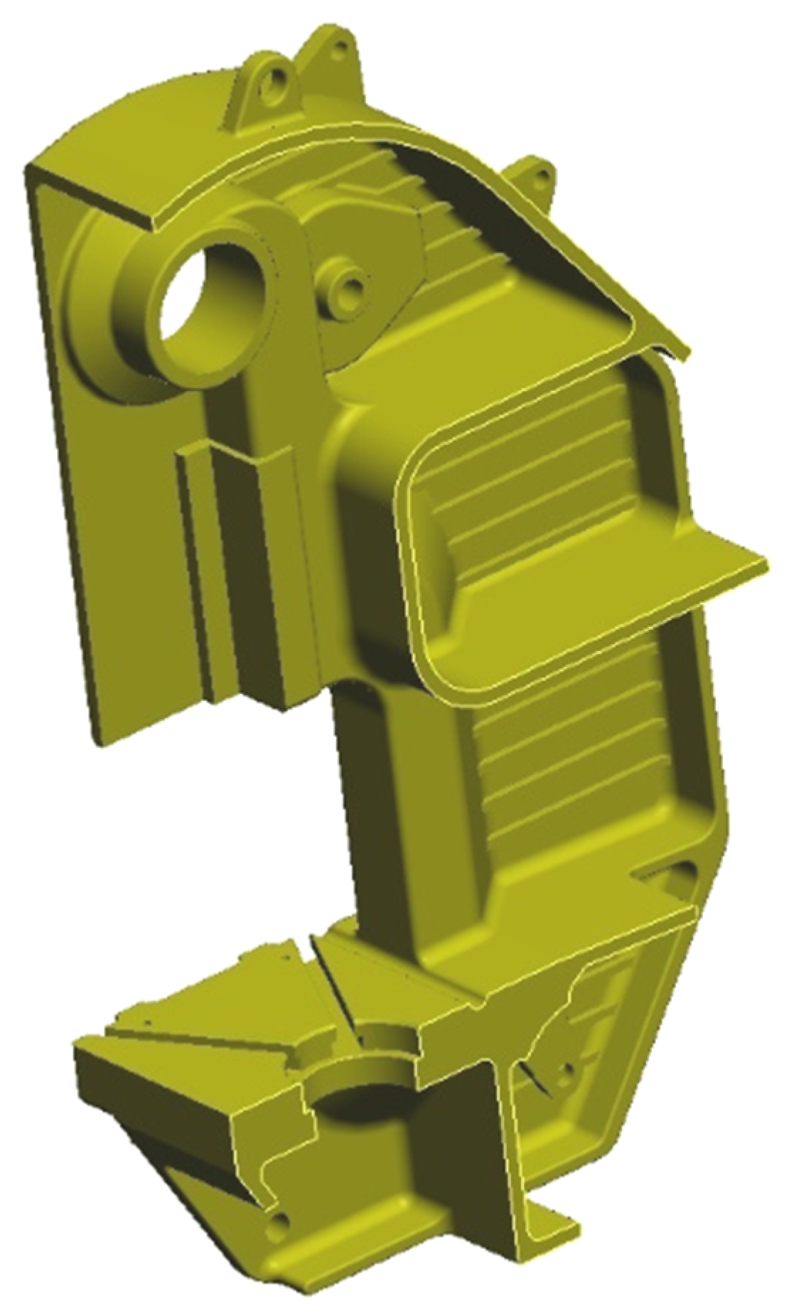
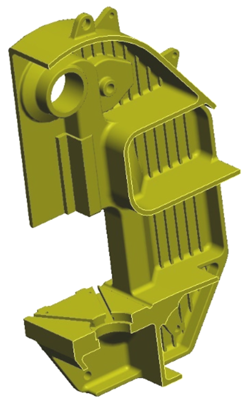
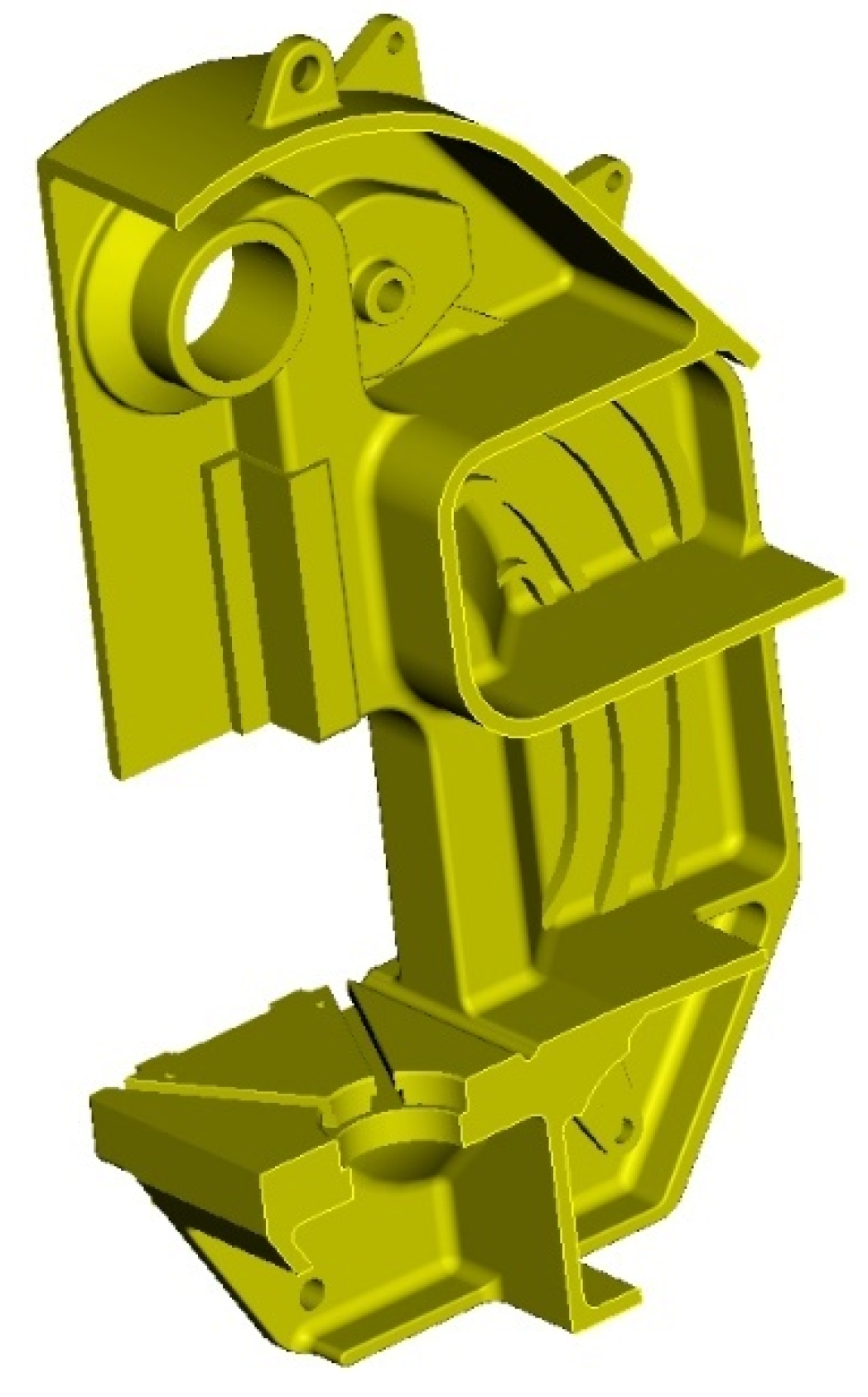
Starting from a reference model—the cast frame of the Romanian PAI 25 press (
Figure 1a)—the research was targeted mainly at developing new constructive solutions of mechanical press C-frames that would ensure the decrease of the maximum stress values in the critical areas. A related objective, not to be neglected, was also to increase the rigidity of the frame, with immediate consequences on operational energy consumption of the respective machine for at least one life cycle. The entire research is in accordance with the concept of sustainable development, that reflects the responsible concerns of the scientific community, the civil society, and the political stakeholders in view of environment and natural resource conservation and as such to ensure a balanced and long-term development, including future generations.
2. Methodology
2.1. The Reference Model
The entire study was conducted in relation to the constructive solution of a press frame considered as reference. For this, the frame of a press which is known and recognised for its good performance was selected, validated over time, namely PAI 25 (Automated Tilt Press, of nominal force F
N = 25 ton), as shown in
Figure 1, frequently encountered in machine manufacturing companies of Romania. The 3D model of the PAI 25 press frame, as shown in
Figure 1b, is in accordance with the original technical documentation. The model used in this paper for experimental testing of rigidity, as shown in
Figure 1a, differs only by a few details with virtually zero impact on the rigidity and deformation of the frame. PAI 25 is a single action crank press with its main shaft parallel to the press front and a solid C-frame cast from St 50-2 cast steel, according to DIN, for which the following values were considered: Young’s modulus
E = 210,000 N/mm
2, shear modulus
G = 80,000 N/mm
2, and ν = 0.3 for the Poisson’s ratio.
Initially, the study was aimed at reducing the metal consumption entailed by the manufacturing of mechanical press C-frames. As it progressed, the research was widened, in order to consider the reduction of material and energy consumption, both in the manufacturing and operation phase. The study of the rigidity of the frame was the main objective, the experimental research focused on this aspect. The state of stresses was analysed only in a virtual environment, using FEA. For this purpose, several families of frames, similar to the reference one, were designed. All new models rigorously respect the reference model, namely the PAI 25 press frame. The differences are well delimited and concern only the lateral walls and/or the front pillars. This approach allows, for the obtained results, the extrapolation for any other type or dimension of cast C-frame.
All models were designed consistently using PTC Pro/ENGINEER Wildfire 4.0 software [
20]. Further, IBM Catia V5R16 [
21] was used for the study of the states of stress under rigorously identical conditions of stress and restrictions for all considered constructive solutions.
2.2. Novel Constructive Solutions
Two new groups of frames were obtained by modifying and ribbing the lateral walls. The constructive solutions combining these two features were considered, thus ribbed wall frames and frames of various wall thickness. While not imperative, an objective connected to the research and was permanently considered to ensure that the identified solutions entail a minimum increase of the required volume of metal. Compared to the reference solution, which weighs 1147.5 kg, the ribbed models weigh 8–21 kg more, depending on the density and orientation of the ribs [
22].
The first new solutions that were deigned were exploratory, they were meant to identify the influence of wall thickness on the state of stress that occurs in the frame body. In relation to the reference construction of the frame with a wall thickness of g = 20 mm, four new variants were defined for the purpose of the study. The new variants had wall thickness values of 18, 19, 21 and 22 mm, respectively.
The ribbing of the lateral walls was aimed at increasing their rigidity, and implicitly of the entire frame. The following quantities below define the geometry of the ribs,
Figure 2 [
22,
23]:
H—rib height;
x—rib thickness;
l—distance between two parallel ribs (in the case of equally spaced ribbing).
Obviously, the thickness g of the frame lateral wall was also considered. As the frames were obtained by casting, the following quantities also had to be indicated:
R1—tip radius of the rib;
R2—base radius connecting the rib to the wall;
ω—tilting angle of the rib lateral wall.
In all cases the following values were adopted: h = 20 mm; x = 12 mm; R1 = 2 mm; R2 = 5 mm; ω = 5°.
The ribbing of the lateral walls can be diverse regarding orientation and density. The studied models considered horizontal or vertical ribs, or ribs tilted in relation to the horizontal by an angle of α varying by an increment of 10 degrees. The models where α = 0° have horizontal ribs (
Figure 3), those where α ∈ {10°, 20°, …, 80°} are “left tilted” (
Figure 4), namely towards the front face of the frame, those where α = 90° are vertical ribs (
Figure 5), and the models where α ∈ {100°, 110°, …, 170°} are “right tilted” (
Figure 6), namely towards the back of the frame. For intersecting ribbed frames, the inclination angle for the second set of ribs is denoted by β.
Models with intersected ribs were also considered and studied, as shown in
Figure 7, the ribs being symmetrically tilted or not, reciprocally perpendicular, or not.
A singular and particular model involved curved and unevenly spaced ribs, oriented along certain isocline curves of the stress state in the lateral walls of the reference model frame (
Figure 8).
A patent of invention has been obtained for the conceived ribbed frames [
24].
Evidently, rib density described by the rib spacing parameter l influences the state on tensions occurring in frame body. In the designed and studied models the equidistant ribs are spaced at l ∈ {50, 75, 100} mm. For exploratory purposes, only for horizontally and vertically ribbed frames, models were devised and studied with unevenly spaced ribs.
The combination “ribbed frame” + “different wall thickness” was studied only for frame models with horizontal and vertical ribs, in order to identify the cumulative effect of the two modifications. The study was conducted for models with wall thickness g ∈ {18, 19, 20, 21, 22} mm and for equidistant ribs spaced at 50, 75 or 100 mm, respectively, as well as those spaced unevenly. Only these combinations generated 40 constructive variants.
The large number of solutions (and variants) required their identification by codes. This was achieved by an alpha-numerical system that would include the specific relevant aspects of the studied solutions, namely:
- -
the type of press corresponding to the frame;
- -
the lateral wall thickness;
- -
the distance between the equidistant ribs;
- -
the tilting angle of the identically oriented ribs in relation to the horizontal, measured clockwise.
Table 1 features these identifiers.
The frame identifier codes for the examples in the table above read as follows:
- (1)
B-PAI25_g20_e75_α10 ⇔ “PAI 25 press frame, with lateral walls of thickness g = 20 mm, with lateral walls ribbed at the interior, equidistant parallel ribs spaced at 75 mm, tilted at an angle α = 10° measured clockwise in relation to the horizontal”;
- (2)
B-PAI25_g19_e100 + e100_α10 + β100 ⇔ “PAI 25 press frame, with lateral walls of thickness g = 19 mm, with lateral walls ribbed at the interior, equidistant parallel ribs spaced at 100 mm, one set of ribs tilted at an angle α = 10° and another set of ribs tilted at an angle β = 100° (perpendicular ribs), both measured clockwise in relation to the horizontal”;
- (3)
B-PAI25_g21_var._curv ⇔ “PAI 25 press frame, with lateral walls of thickness g = 21 mm, with lateral walls ribbed at the interior, non-equidistant ribs displayed by a curve”.
Where applicable, one or more identifier code sequences can be left out. For example, identifier code B-PAI25_g20 corresponds to a “PAI 25 press frame with lateral walls of thickness g = 20 mm, with unribbed lateral walls”, which is exactly the reference construction.
2.3. Research Methodology
All devised frame models were studied under identical conditions of stress and quasi-identical meshing, that allows their comparative analysis in relation to the constructive solution of reference. For each frame model, the study included the state of stress, the state of deformation, the estimated stiffness, and the required volume of material.
The discretisation of the 3D-models was achieved by tetrahedral elements [
20,
25],
Figure 9. In the model frame used for reference, 55,912 nodes and 29,743 elements were obtained. In the studied models with ribbed lateral walls, depending on their geometrical complexity and the difference in volume, the number of nodes and elements is greater, in general, by up to 10% [
20], the common values being ≈61,000 nodes and ≈32,500 elements. Greater values can be found in models with more dense ribbing, spaced at 50 mm (≈63,000 nodes and ≈33,500 elements), while the maximum values pertain to the models with intersected ribs (≈67,000 nodes and ≈36,000 elements). The extremes correspond to frame B-PAI25_g18 (55,520 nodes and 29,567 elements), without ribs and with a small lateral wall thickness, and to frame B-PAI25_g20_e75_α45 + β135 (68,290 nodes and 36,557 elements), with tilted intersected ribs.
All models were loaded realistically, in static conditions, by a uniformly distributed force acting upon both the table working surface and the superior part of the main shaft bearing bores [
20,
25] (
Figure 10). The force was considered equal to the nominal force F
N = 250 kN, the maximum admissible force. The constraints of the frame reflect its connection to the press base by means of four bolts.
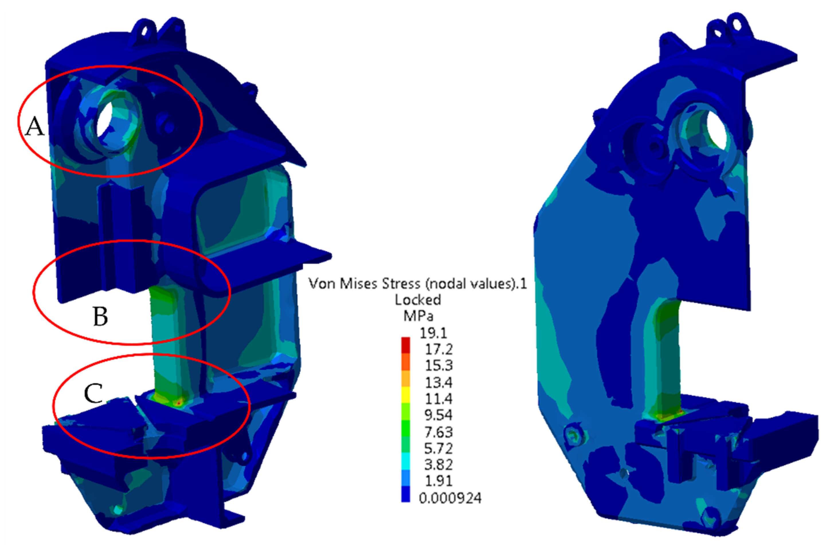
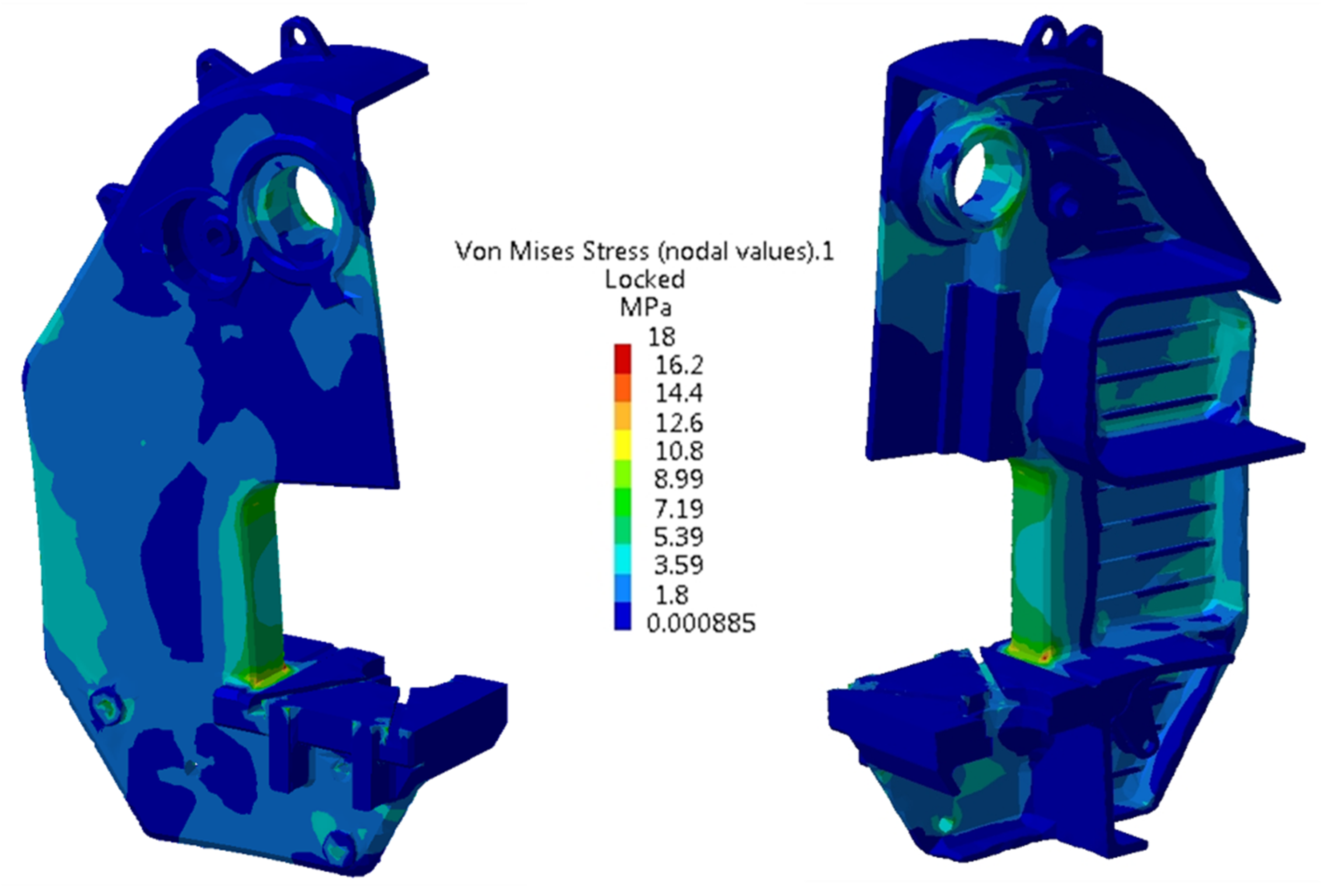
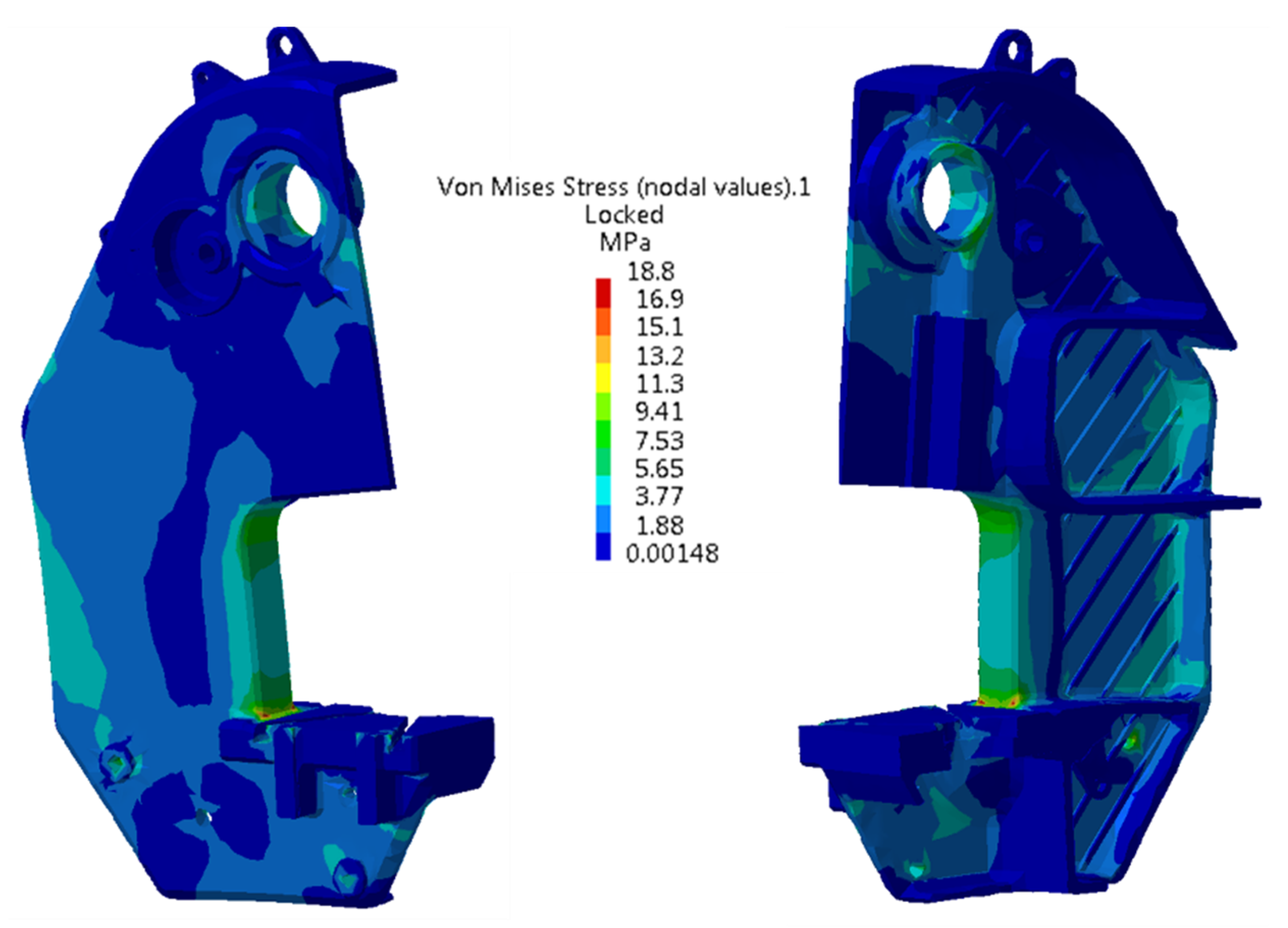
The finite element analysis of the reference model, the B-PAI25_g20 frame, revealed three areas of high stress in the frame body,
Figure 11:
- A.
the inferior area of connection of the front pillars to the frame table (elongation stress);
- B.
the superior area of connection of the front pillars to the superior part of the frame (elongation stress);
- C.
the area of the main shaft bearing bore (crushing stress).
4. Discussion
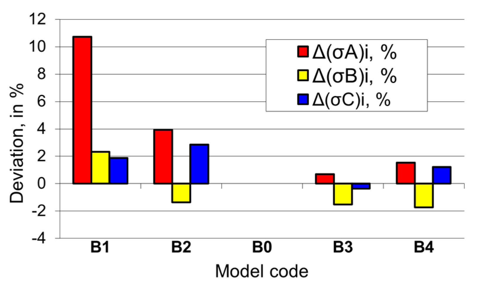
The thickness modification of the lateral walls in the vicinity of the 20 mm value causes an increase of the maximum stress in critical area A. The increase is significant if the wall thickness is smaller than 20 mm, and less significant if the wall thickness is greater than 20 mm. The modification of the lateral wall thickness has a minor, even insignificant effect on the maximum stress in critical areas B and C. The variations, expressed as percentages compared to the reference model, are more evident than those in absolute values, as shown in
Figure 17.
Adopting a 20 mm lateral wall thickness is a good decision. Considering only the maximum values in the critical areas, a 21 mm lateral wall thickness may represent an alternative but would cause an important increase in the volume of metal required for the manufacturing of the frame.
Models with lateral walls with horizontal ribs spaced at 75 mm, as shown in
Figure 18, reveal a small but interesting (as a percentage) variation of the maximum stress values in the critical areas. An important decrease (by more than 20%) of the maximum stress in critical area C of the model of small wall thickness (
g = 18 mm) could be noticed, most probably due to the decrease in stiffness of the frame in the respective area, and a considerable decrease (by almost 9%) of the maximum stress in critical area A of the model with large wall thickness,
g = 22 mm, represents a good evolution in relation to model B4 (
Table 2), which is un-ribbed and of the same lateral wall thickness. In the model of the same lateral wall thickness as that of the reference model, the horizontal ribbing spaced at 75 mm (model B8) determines an increase of the maximum stress by more than 5% in critical area A, its decrease by ≈1.77% in critical area B and increase by 3.76% in critical area C. As a conclusion, the model with horizontal ribs spaced at 75 mm is not recommended, as the maximum stress in the critical areas is generally greater than in the reference model.
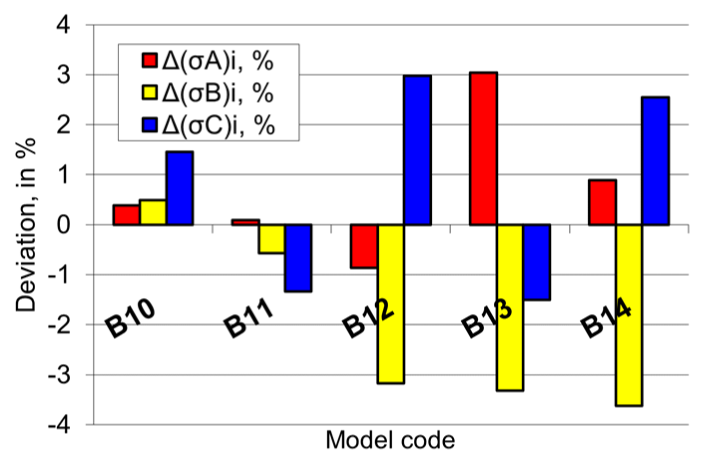
In frame models B10–B14 with high density vertical ribs spaced at 50 mm, the increase of lateral wall thickness determines an alternating evolution of the maximum stress in critical area A, however with a reduced variation ranging from 11.2 to 11.7 MPa, that is in the interval (−1 to +3)% in relation to the corresponding value determined for reference model B0,
Figure 19.
The maximum stress in critical area B decreases continuously with the increase of the lateral wall thickness, although not considerably, with the tendency of stopping slightly under 3% in relation to the corresponding value of the reference model. The maximum stress in critical area C, although relatively small as absolute values, vary slightly within a narrow range (4.06 to 4.25) MPa, that is (−1.5 to +2.98)% around the corresponding value of the reference model, but alternatingly with the increase in lateral wall thickness. Model B12, of 20 mm lateral wall thickness and vertical ribs spaced at 50 mm is the only one where the maximum stress in critical areas A and B is simultaneously smaller than in the reference model, what renders this solution worth considering.
The vertical ribbing of the lateral walls (models B15–B19) had the positive effect of reducing the maximum stress in critical area B (for example by ≈1.43% in model B17 with
g = 20 mm and vertical ribs spaced at 75 mm), and the negative effect of the undesired increase of maximum stress in critical area A (for example by more than 7% in the same model B17), as shown in
Figure 20. The (nearly linear) decrease of stress in critical areas A and B with the increase of lateral wall thickness is evident.
The same tendency of the maximum stress to increase in critical area A and slightly decrease in critical area B is identified in the models with vertical ribs spaced at 100 mm (models B20–B24),
Figure 21. In model B22 the maximum stress in critical areas A and B (the most important ones) are simultaneously smaller than the corresponding ones in the frame used for reference, but the gain is, however, insignificant.
Rib density has an evident influence on the maximum stress in the critical areas, it is significantly more visible if expressed in percentages, as shown in
Figure 22. In relation to the reference model, an increase of more than 7% of the maximum stress in critical area A is noticed in the model with ribs spaced at 75 mm. In critical area B, there is a slight decrease (0.9–3.2)% of the maximum stress at the models with ribs spaced at 50 and 100 mm, and increases by (2–3.69)% of the maximum stress in critical area C, but reduced as absolute values. The high density of ribs seems to be favourable.
“Left tilted ribbing” definitely has a positive effect on the maximum stress in critical area B and a definitely unfavourable effect on the maximum stress in critical areas A and C,
Figure 23.
The maximum stress in area B decreased by ≈3% in the majority of studied cases, with a maximum of 4.49% in model B27 with ribs tilted at 30°. It needs be pointed out that model B27 is one of the “left tilted” ribbed models that ensures one of the best increases in stiffness [
16]. The maximum stress in critical area A increases, with a single exception (model B26), by (0.6 to 1.6)%, the minimum pertaining to model B28, with ribs tilted at 40°. The maximum stress in critical area C in all cases is greater than in the reference model, the increase typically being smaller than 2% and, in any case, small as absolute value. The favourable models are those with ribs tilted at 30° and 40°, where the maximum stress in critical areas A and C increases slightly, and the stress in critical area B decreases significantly.
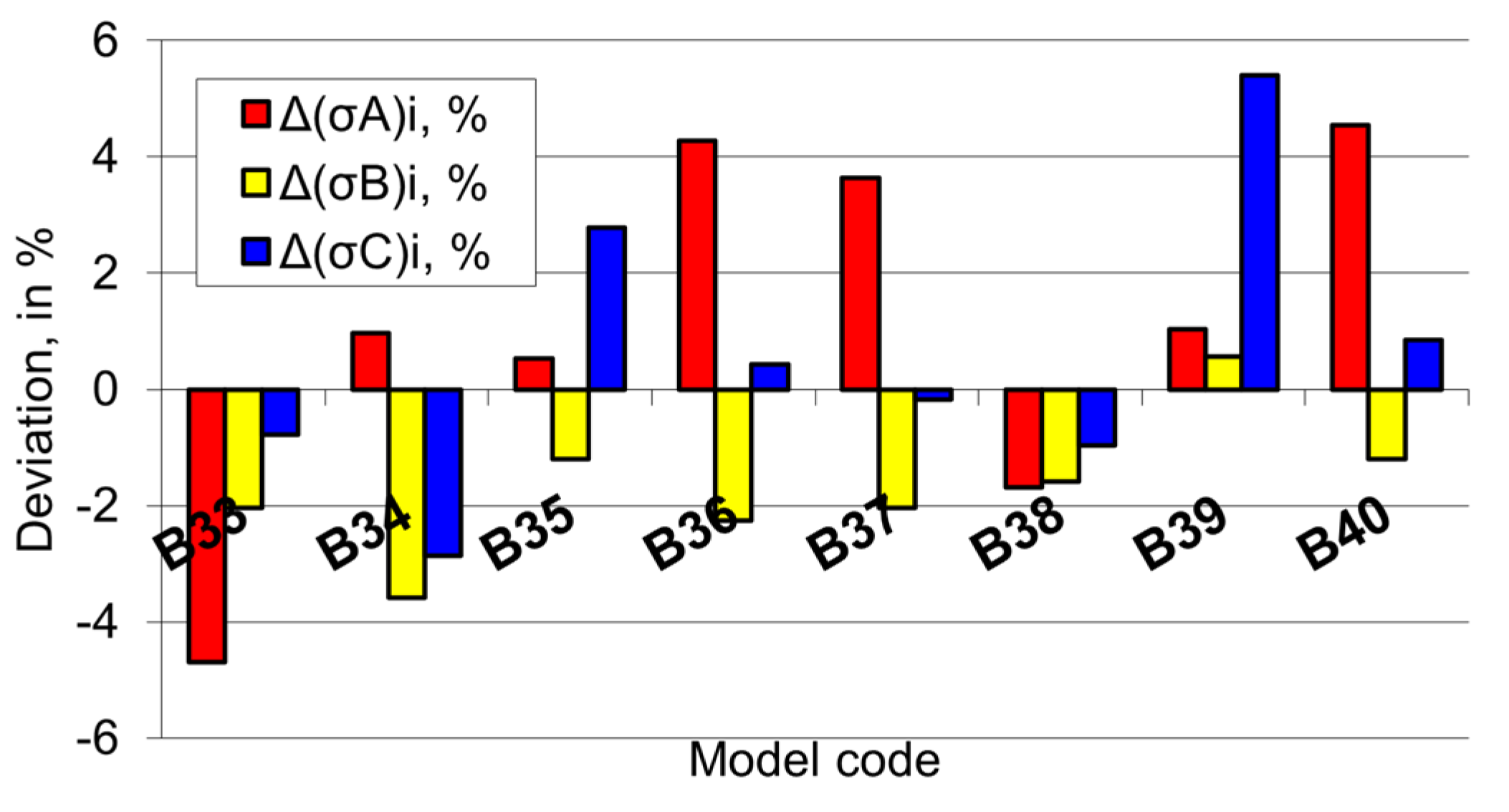
The improvement of the stress state is evident in critical area B,
Figure 24, also in the “right tilted” rib models, the maximum stress values are smaller than those in the reference model by ≈2% in most of the studied cases. The maximum stress in critical areas A and C are not consistently smaller or greater than the similar ones in the reference model, the variation for the studied model having the interval of (–5 to +5) %. It can be noticed that in two of the studied models, B33 and B38, the maximum stress in all three critical areas is simultaneously smaller than those in the reference model. Model B33 becomes the favoured one, as it is also the second-best solution under the aspect of stiffness increase [
16]. In the same context, it can be also remarked that in model B39, the maximum stress in the critical areas is simultaneously greater than in the reference model. B39 is the least favourable model, being at the same time the model with the smallest stiffness increases of all studied “right tilted” and 75 mm spaced rib models.
In models with intersected ribs, no consistent decrease of the maximum stress in the critical areas can be noted,
Figure 25, as a reflection of a possible cumulative positive effect on the increase in stiffness caused by the simultaneous presence of “left tilted” and “right tilted” ribs.
In all models with intersected ribs (B41–B46), the maximum stress in critical area A is greater than in the reference model, and significantly greater than 13% in model B43, while the maximum stress in critical area B is smaller, typically by 1 to 2%, and exceptionally by ≈ 5%. The differences recorded between the maximum stresses in critical area C in relation to the corresponding stress in the reference model are of little significance.
The most favourable solution would be model B41, with intersected horizontal and vertical ribs, where the increase of less than +1.2% of the maximum stress in critical area A is well compensated by a decrease of nearly −2% in critical area C. Model B41 is to be considered the best as it is the model that ensures the largest increase in stiffness (of +3.09%) of all frame models with straight ribs, intersected or not, regardless of their orientation [
16].
Only model B47, with curved ribs, ensures a greater increase in stiffness by +3.64% [
16]. In model B47 the maximum stress in critical area A is 5.7% greater than in the reference model, a significantly greater increase than that of less than +1.2% in model B41, but smaller than the maximum stress in critical area B −4.98% as compared to nearly −4.26% in model B41.
5. Conclusions
In the body of the C-frame press three “critical” areas can be identified: the inferior area connecting the front pillars to the frame table (area A), the superior area connecting the front pillars to the upper part of the frame (area B), and the area of the main shaft bearing bore (area C). A modality, with realistic results, of reducing the stress state in critical areas of the cast C-frame of a mechanical press is the ribbing of the interior side of its lateral walls, combined or not with a modified wall thickness.
Several families of 3D models of various frames were developed, differing by the lateral wall thickness, the space between two neighbouring ribs and by rib orientation. Because of the large number of proposed models, an identification codding was established.
The critical areas A and B are the most intensively strained and require the focus of any study on the distribution and the evolution of stress in C-frames of the considered type. The magnitude and variation of stress in the critical area C being a criterion of lesser significance. In the studied models, the maximum values of stress in the critical areas rarely differ by more than 5% from the corresponding values of the reference model. Generally, without having identified a variation law, in the new models the stress in critical area A is greater, while the stress in critical area B is smaller. As to the stress in critical area C it can be asserted that in the various studied models, they differ slightly in relation to the corresponding stress in the reference model, particularly as absolute values.
In models with intersected ribs, no consistent decrease on the maximum stress in the critical area occurs. In only two of the studied models, both with right tilted ribs, the values of the maximum stress in the critical areas are simultaneously smaller than in the reference model; these models are not the ones that at the same time ensure the greatest increase in stiffness.
The study reveals that to reduce the values of the maximum stresses in the critical areas of the frame, the change in the thickness of the side walls is not justified.
The large number of studied models reveals both positive examples, whose study deserves to be developed with the refinement mesh, and negative examples, in which the maximum stress in the critical areas are higher than in the reference model.
The best results in terms of maximum stress values in critical areas are identified in model B33, with ribs inclined to the right at 100° and spaced at 75 mm. Models B34 and B38, both with right-angled ribs at 110° and 150° respectively, spaced at 75 mm, also provide good results. The results obtained for models B12 and B22 in which the ribs are vertical and are spaced at 50 and 100 mm are satisfactory. In all these models the ribs are vertical or inclined to the right. It is necessary to confirm the results by resuming the study using meshes with an increased number of nodes.
All models with intersecting and curved ribs are not recommended. With these, there is a decrease in the tension in the critical zone B, but also an important increase in the values of the tensions in the critical zone A.
The frame models with ribbed lateral walls present the greatest increase in stiffness (model with curved ribs and model with intersected horizontal and vertical ribs) also display improvements of the stress states but are not the best and not remarkable.
The ribbing of the frame determines a modest increase in weight, with 8 to 21 kg, representing 0.7 to 1.83% of the weight of the reference model, depending on the density and orientation of the ribs.


