Article

Semi-Analytical Solution for Elastoplastic Deflection of Non-Prismatic Cantilever Beams with Circular Cross-Section

Faculty of Civil Engineering and Architecture, University of Niš, 14 Aleksandra Medvedeva, 18000 Niš, Serbia
*
Author to whom correspondence should be addressed.
Appl. Sci. 2022, 12(11), 5439; https://doi.org/10.3390/app12115439
Submission received: 4 May 2022 / Revised: 21 May 2022 / Accepted: 24 May 2022 / Published: 27 May 2022
(This article belongs to the Section Mechanical Engineering)

Abstract

:

Featured Application

The proposed semi-analytical solution is proved as reliable for determining the force–displacement relation of the vertical components of the innovative steel seismic energy dissipation device described in the paper, and also for any engineering problem involving behavior of non-prismatic cantilever beams with a circular cross-section under bending.

Abstract

A solution for the elastoplastic deflection of cantilever beams with linearly variable circular cross-section loaded by shear force at the free end, which is suitable for practical use, has not yet been developed. A semi-analytical solution for such a problem is proposed in this paper. The solution involves beams made of homogenous and isotropic materials with bilinear elastoplastic strain hardening behavior. The Bernoulli–Euler formula is used for determining the elastic deflection. However, for the plastic domain of material behavior, the differential equation of beam bending does not have a solution in closed form. Therefore, an incremental procedure for determining the curvature of the plastified region of the beam is suggested. Deflection of the cantilever beam is calculated via integration of the approximated function of the beam curvature. The proposed semi-analytical solution is validated using experimental results of the seismic energy dissipation device components which have been selected as a sample of a real engineering system. Also, validation is done via finite element analysis of six different cantilever beam models with varying geometric and material characteristics. A satisfying agreement between the proposed semi-analytical results and the subsequent experimental and numerical results is herein achieved, confirming its reliability.

Graphical Abstract

1. Introduction

The stress-strain analysis of cantilever beams is frequently present in engineering practice. Therefore, a large number of researchers have been working in these fields. Initial research included analysis of the elastic deflection of a beam with an assumption of small deformations and displacements [1]. Further research, which included large elastic deformations of cantilever beams loaded by concentrated force at the free end, involved the resolving of differential equations applying elliptic integrals [2]. The complexity of this solution directed the following research towards the development of different semi-analytical methods for finding the solution for the problem of large elastic deformations of cantilever beams [3]. Additionally, the elastic deflection of beams with linearly variable depth of the cross-section and semi-rigid supports was analyzed [4]. Different numerical methods for solving the fourth order ordinary differential equation of beam deflection were developed, and they are systematized in the reference [5]. Lately, elastic deflection of non-prismatic cantilever beams [6], as well as thin-walled beams with a curvilinear open cross-section, have been analytically and numerically studied [7].
Besides the elastic behavior, the materials possess plastic behavior where irreversible strains occur. The broadening of research on the elastoplastic deformation of cantilever beams is thus required.
Research of the elastoplastic deflection of cantilever beams has been focused on the analysis of the beams with constant rectangular cross-section and elastic–perfectly plastic material without hardening in the plastic domain [8,9,10,11].
Numerical–analytical methods for solving the elastoplastic deflection of prismatic cantilever beams subjected to axial force and bending moment at the free end were proposed, and they included elastic–perfectly plastic materials [12] and elastoplastic materials with strain hardening [13]. Research also covered the influence of the inclined load on the large deflection of elastoplastic cantilever beams [14]. The elastoplastic deflection of cantilever beams with rectangular cross-section loaded by shear force at the free end were analyzed for different non-linear material models [15,16,17].
Finite deflection of a slender cantilever beam with a predefined load application locus was analyzed using numerical methods for beams with constant rectangular cross-section and elastic-perfectly plastic material [18,19]. Simply supported beams with linearly variable depth of the cross-section were investigated in [20].
Analyses of elastoplastic deflection of cantilever beams mainly treated prismatic rectangular beams. In the case of circular cross-sections, the plastic moment–curvature relationship was developed for elastic–perfectly plastic material [21,22,23]. An approximate solution for plastic the moment–curvature relationship which replaces a circular cross-section with the equivalent rectangular one was proposed in [24].
In recent years, piezoelectric materials have drawn attention and been implemented in structural health monitoring systems. Therefore, an explicit exact analytical solution for the shape deformation control of smart laminated cantilever piezo composite hybrid plates and beams was proposed [25]. The solution covers a variety of complex loading systems. Although this solution is universal, covering both isotropic and orthotropic structures, it was developed for elastic materials and can hardly be implemented for the elastoplastic strain hardening deflection of cantilever beams with linearly variable cross-section, which is the subject of this paper.
The exact solution of the elastoplastic deflection of cantilever beams subjected to shear force at the free end was not developed due to the complexity of the mathematical model.
Based on the above-mentioned data, one may conclude that the solution of the elastoplastic deflection of cantilever beams with linearly variable cross-section subjected to shear force at the free end, and with strain hardening of the material in a plastic domain is not available.
The necessity for this solution is present in real engineering problems, e.g., considering the innovation steel seismic energy dissipation device for the base isolation of structures, which is proposed within the frame of the project Seismo-Safe 2G3-GOSEB Building System, funded by the Innovation Fund of the Republic of Serbia and European Union and World Bank [26]. The research within this project resulted in the patent of a new innovation energy dissipation device [27].
A semi-analytical solution for the elastoplastic strain hardening bending of a cantilever beam with a linearly variable circular cross-section loaded by shear force is presented in this paper. The proposed solution is validated with the results from an experimental testing of the innovation of steel seismic energy dissipation device components.
Furthermore, the elastoplastic deflection of six different models of the cantilever beam is calculated using the proposed semi-analytical solution and the finite element method (FEM) using the software package Abaqus/Standard, and the results are compared. The models are varied regarding geometric characteristics of the beam and mechanical characteristics of the material.
A comparative analysis of the results obtained with the proposed semi-analytical solution and the experimental and numerical results are conducted in order to validate the proposed solution.

2. Solution for the Elastoplastic Bending of the Cantilever Beam

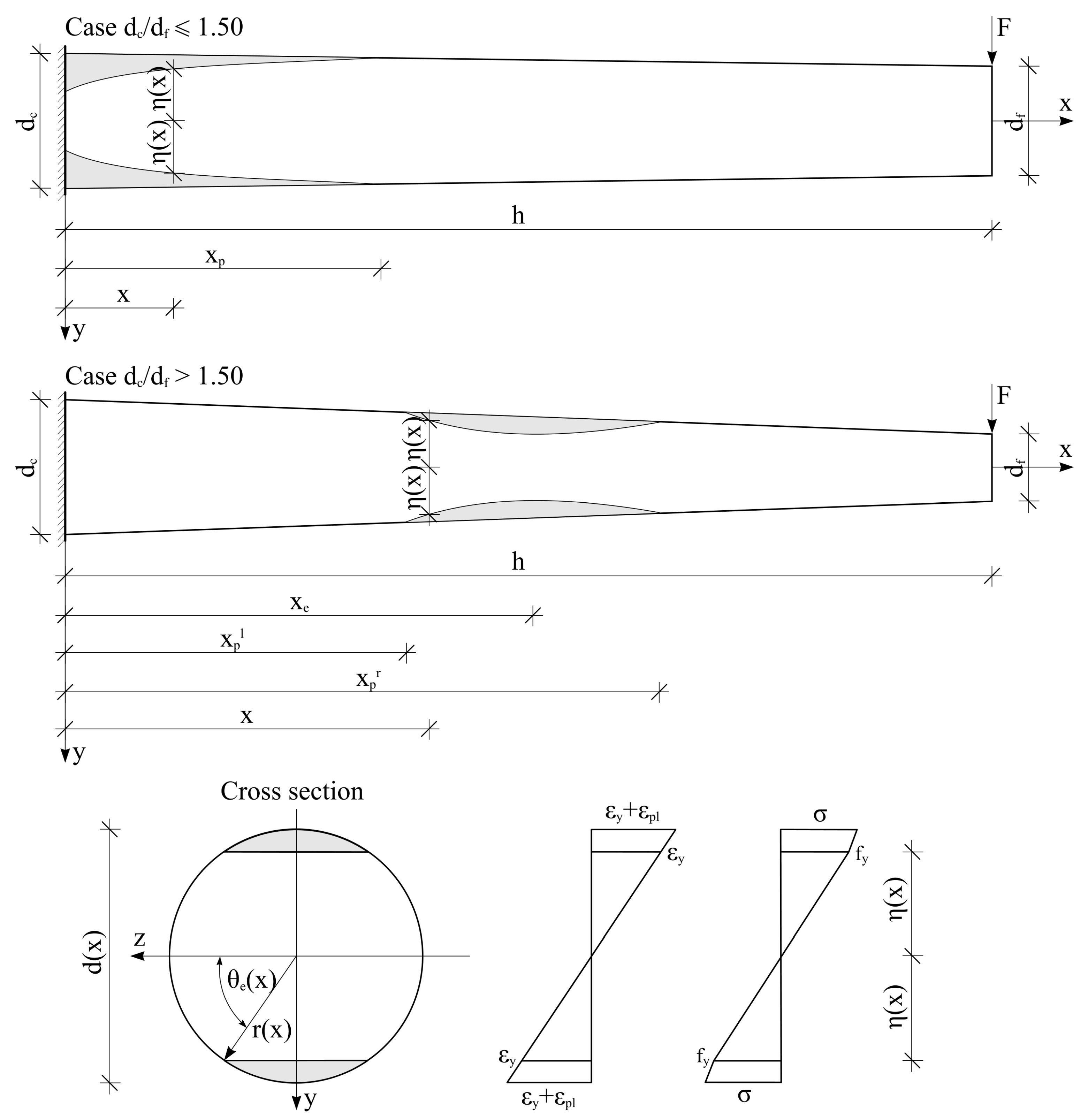
The analysis considers a cantilever beam with a linearly variable diameter of the circular cross-section along the beam made of homogenous and isotropic material with strain hardening in the plastic domain. The cantilever beam is loaded by shear force at the free end. The aim is to define the mathematical model for the calculation of its deflection v(x) and slope φ(x) (Figure 1). According to the adopted material model, the stress–strain analysis can be separated into the analysis in the elastic and in the plastic regime of the material behavior.

2.1. Elastic Regime

The cantilever beam is in the elastic regime until the value of the maximum normal stress in the cross-section reaches the yield stress of the material (fy). When the material is in the linear elastic regime, the bending moment in the arbitrary cross-section is proportional to the intensity of the force and the perpendicular distance between the force and the cross-section (lever arm); therefore, the function of the bending moment along the cantilever beam axis (Figure 1) can be written as:
M ( x ) = F ( h x ) .
The maximum bending moment is in the cross-section at the clamped end of the cantilever beam:
M max = F h .
Based on Figure 1, the function of the circular cross-section diameter change and the function of the moment of inertia of the cross-section, along the axis of the cantilever beam, can be derived as follows:
d ( x ) = d f + ( d c d f ) h x h ,
I z ( x ) = d ( x ) 4 π 64 = [ d f + ( d c d f ) h x h ] 4 π 64 .
The maximum value of the normal stress in the cross-section is not necessarily in the section at the clamped end, because the normal stress is not only the function of the bending moment, but also the function of the section modulus of the cross-section, which itself is a third-degree function of the coordinate along the cantilever beam axis:
σ ( x ) = M ( x ) I z ( x ) d ( x ) 2 = 32 F ( h x ) [ d f + ( d c d f ) h x h ] 3 π .
The position of the cross-section (xe) with the maximum value of the normal stress can be defined based on the definition of the extremum of the function, i.e., via equalization of the first derivative of the normal stress function with zero:
d σ ( x ) dx = 96 ( d c d f ) F ( h x ) [ d f + ( d c d f ) h x h ] 4 π h 32 F [ d f + ( d c d f ) h x h ] 3 π = 0 ,
x e = ( 2 d c 3 d f ) h 2 ( d c d f ) .
Equalizing the relation (7) to zero, the condition in which the critical section is at the clamped end of the cantilever beam is defined as follows:
x e = ( 2 d c 3 d f ) h 2 ( d c d f ) = 0 2 d c 3 d f = 0 d c d f = 1.50 .
Based on the relation (8), it can be concluded that the normal stress has the extreme value in the cross-section at the clamped end when the diameter ratio of the cross-section at the clamped end and at the free end of the cantilever beam (hereinafter, cross-sections diameter ratio) is lower than or equal to 1.50, while in the case when this ratio is greater than 1.50, the extreme value of the normal stress is in one single cross-section located along the beam axis.
Taking into account previous consideration, the maximum value of the normal stress in the cross-section in the case when the cross-sections diameter ratio is lower than or equal to 1.50, is:
σ max = M max I z y max = 32 F h d c 3 π ,
while in the case when the cross-sections diameter ratio is greater than 1.50, this value is:
d ( x e ) = 1.50 d f ,
I z ( x e ) = d ( x e ) 4 π 64 = ( 1.50 d f ) 4 π 64 ,
σ max = M ( x e ) I z ( x e ) d ( x e ) 2 = 32 F ( h ( 2 d c 3 d f ) h 2 ( d c d f ) ) ( 1.50 d f ) 3 π .
The intensity of force (Fy)—corresponding to the yield of the material—can be defined based on the condition that the maximum normal stress is equal to the yield stress of the considered material model:
σ max = 32 F h d c 3 π = f y F y = f y d c 3 π 32 h ( case d c d f < 1.50 ) ,
σ max = 32 F ( h ( 2 d c 3 d f ) h 2 ( d c d f ) ) ( 1.50 d f ) 3 π = f y F y = f y ( 1.50 d f ) 3 π 32 ( h ( 2 d c 3 d f ) h 2 ( d c d f ) ) ( case d c d f > 1.50 ) ,
and the bending moment (My) that corresponds to the yield of the material is as follows:
M y = F y h = f y d c 3 π 32 ( case d c d f < 1.50 ) ,
M y = F y ( h x e ) = f y ( 1.50 d f ) 3 π 32 ( case d c d f > 1.50 ) .
Relations (13) and (15) define shear force intensity at the free end of the cantilever beam and the bending moment that correspond to the beginning of the plastification of the material in the case when the cross-sections diameter ratio is lower than or equal to 1.50, while relations (14) and (16) define those values in the cases when the cross-sections diameter ratio is greater than 1.50.
The beam deflection analysis starts with the basic relationship between curvature and deflection:
κ = d 2 v dx 2 [ 1 + ( dv dx ) 2 ] 3 2 .
In the case of small deformations, the slope dv/dx is a small value, and consequently the square of the slope is a small value of the higher order and can be neglected [10]. Therefore, the deflection curve can be presented in the following form:
κ = d 2 v dx 2 .
When the load intensity is lower than the load which corresponds to the beginning of the plastification (F ≤ Fy), the material is in the elastic regime, and the analysis of the force–displacement relationship is linear. In that case, the relationship between curvature, bending moment, and bending stiffness along the axis of the cantilever beam can be defined, based on the Bernoulli–Euler formula, as the following:
κ = d 2 v dx 2 = M ( x ) EI ( x ) ,
with a remark that this relation is of satisfying accuracy when the shear deformation is negligible [10].
Introducing Equations (1) and (4) into relation (19), the differential equation of the elastic curve of the cantilever beam is derived as follows:
d 2 v dx 2 = 64 F ( h x ) E π [ d f + ( d c d f ) h x h ] 4 .
This second order differential equation can be solved via integration. The first integration defines the first derivative of the deflection function. Taking into account the assumption of small deformations (tgφ = φ), the first derivative of the deflection stands for the function of the beam slope (dv/dx = φ). The constants of integrations are defined based on the boundary conditions, whereby the fixed support constrains all displacements and rotations of the cross-section. Finally, the function of the deflection of the cantilever beam in the elastic regime of material behavior is derived as follows:
v ( x ) = 32 F h 4 ( 3 d c h d f h 3 d c x + 3 d f x ) 3 ( d c d f ) 3 E π [ d c ( h x ) + d f x ] 2 32 F h 4 ( 3 d c h 2 d f h ) 3 ( d c d f ) 2 E π ( d c h ) 3 x 32 F h 4 ( 3 d c h d f h ) 3 ( d c d f ) 3 E π ( d c h ) 2 .
Displacement of the free end of the cantilever beam due to the yield force (Fy) can be calculated using Equation (21) as follows:
v ( h ) = 64 F y h 4 d f h 3 ( d c d f ) 3 E π ( d f h ) 2 32 F y h 4 ( 3 d c h 2 d f h ) 3 ( d c d f ) 2 E π ( d c h ) 3 h 32 F y h 4 ( 3 d c h d f h ) 3 ( d c d f ) 3 E π ( d c h ) 2 .
Based on the deflection value of the free end of the cantilever beam (22) and the yield force intensity (13) or (14), the force–displacement relationship in the elastic regime of the material behavior can be defined.
Determination of the elastic deflection of the cantilever beam with a linearly variable circular cross-section presented in this section is relatively simple and widely known, but it represents the starting point in an elastoplastic deflection analysis.

2.2. Plastic Regime

In order to analyze the force–displacement relationship of the cantilever beam in the plastic regime of the material behavior (F > Fy), it is necessary to define the value of the bending moment in the cross-section in terms of the size of the plastified part of the cross-section. The stress-strain state of the cantilever beam in the plastic regime of the material behavior is presented in Figure 2. In the stress-strain analysis of the plastified part of the cantilever beam, the hypothesis that plane sections remain a plane is kept, which implies linear distribution of strains along the y axis of the cross-section (Figure 2) [28,29]. When the intensity of the external force F increases, the plastified zone expands from the most distant fibers toward the neutral axis of the cross-section (along y axis). The plastified part of the cross-section is symmetrical regarding the z axis due to the cross-section symmetry. Besides that, the plastified region propagates along the longitudinal axis of the cantilever beam (x axis). The boundary between the plastic and the elastic region along the cantilever beam axis (xp) can be determined from the condition of strain in the most distant fibers of the cross-section, whose position is defined by xp, is equal to the yield strain of the material (εy):
ε = ε y , ε = σ E , ε y = f y E ,
σ E = F ( h x p ) E d ( x p ) 4 π 64 d ( x p ) 2 = 32 F ( h x p ) E d ( x p ) 3 ,
32 F ( h x p ) E [ d f + ( d c d f ) h x p h ] 3 = f y E .
Equation (25) is of the third degree according to the unknown xp. In cases when the cross-sections diameter ratio is lower than or equal to 1.5, Equation (25) has one real solution used in further analysis (Figure 2). In cases when cross-sections diameter ratio is greater than 1.50, there are two real solutions, where one defines the plastified region along the cantilever beam axis from the critical cross-section toward the fixed support cross-section (xpl), and the second one defines the plastified region along the cantilever beam axis toward the free end (xpr) (Figure 2). At a certain force intensity F, the plastified zone expands until it reaches the clamped cross-section, so with a further increasing of the force intensity, Equation (25) has one real solution which defines the plastified zone along the cantilever beam axis, which is analogous to the case when the cross-sections diameter ratio is lower than or equal to 1.50.
After plastification of the part of the cross-section, the bending moment can be defined via stress-strain analysis of the cross-section at the arbitrary distance x from the fixed support (Figure 2). The part of the cross-section from the neutral axis (z axis) that is in the elastic regime of the material behavior is defined by the distance η(x), while the shaded part of the cross-section in Figure 2 represents the plastified part. In the elastic part of the cross-section, normal stresses are proportional to the strains, and the coefficient of proportionality is the modulus of elasticity (E). According to the adopted material model, in the plastified part of the cross-section, the normal stresses are proportional to the strains, while the coefficient of proportionality is the tangent modulus (Et). At the most distant fibers, the strain is equal to the sum of the yield strain (εy) and the plastic strain (εpl), and the latter increases with the increase of the external force F intensity.
The equations of equilibrium in the cross-section must be satisfied at every moment. The equilibrium of the forces perpendicular to the cross-section is identically satisfied because the cross-section is symmetric, so the resultants of the compression and tension normal stresses are equal.
The bending moment in the cross-section can be defined as follows:
M = F σ ydA .
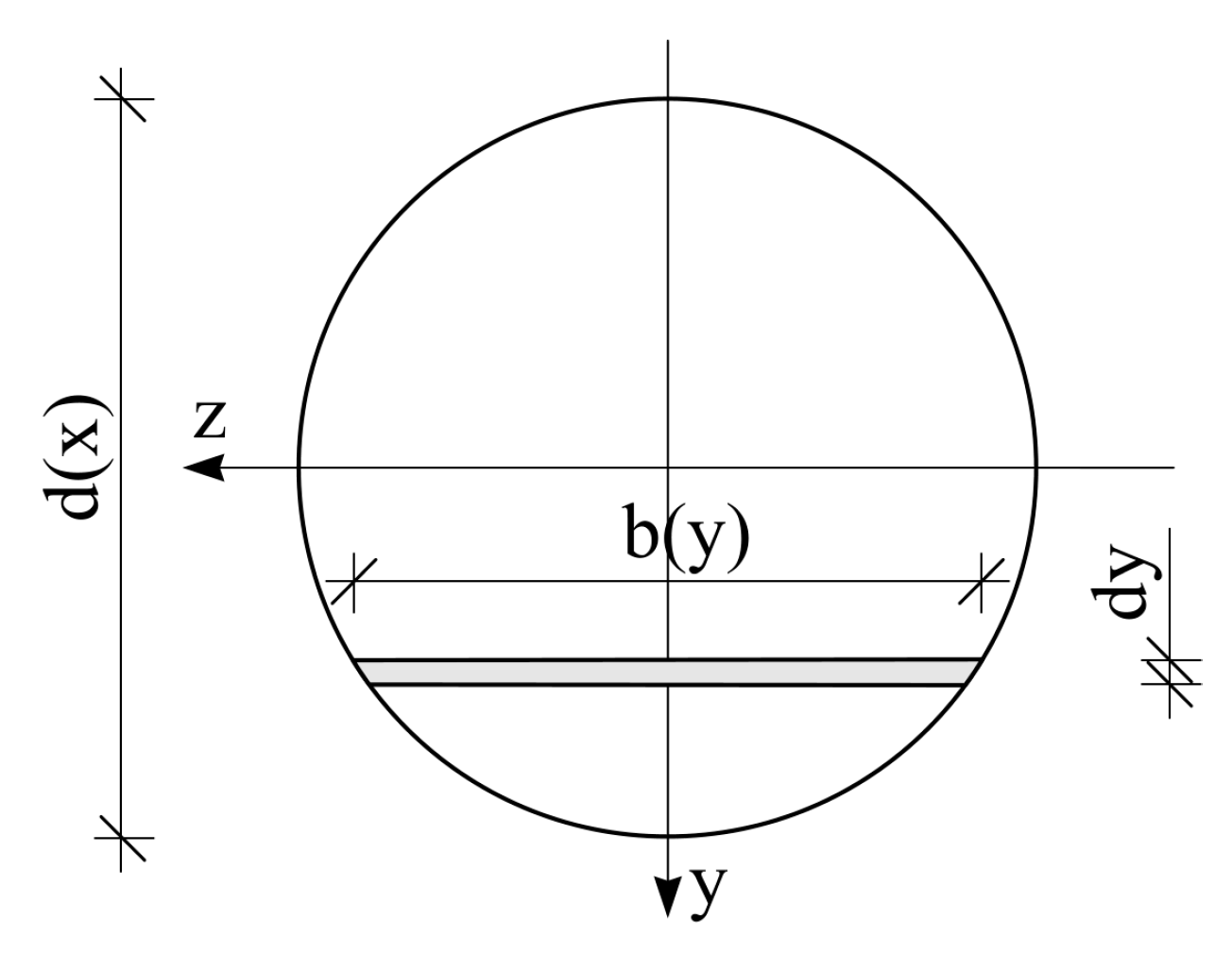
A rectangle of height dy can be adopted as an elemental integration area, where the change of the width of the elemental rectangle along the cross-section can be defined based on Figure 3 as follows:
b ( y ) = 2 r 2 y 2 .
Only half of the cross-section can be analyzed due to the symmetry of the cross-section and normal stress distribution. Substituting Equation (27) into the equation for the bending moment (26) leads to the following:
M = 2 0 r ( x ) σ ( y ) y 2 r 2 ( x ) y 2 dy .
The integral in Equation (28) has to be separated in the analysis of the elastic and the plastic part of the cross-section:
M = 2 { 0 η ( x ) σ ( y ) y 2 r 2 ( x ) y 2 dy + η ( x ) r ( x ) ( ε y E + ε pl ( y ) E t ) y 2 r 2 ( x ) y 2 dy } .
The distribution of the normal stress in the elastic part of the cross-section along the y axis is linear and can be defined as follows:
σ ( y ) = E ε ( y ) = E ε y y η ( x ) .
According to the hypothesis that plane sections remain plane, the distribution of the plastic strains in the plastified part of the cross-section along the y axis is linear:
ε pl ( y ) = ε pl y η ( x ) r ( x ) η ( x ) .
After introducing Equations (30) and (31) into the bending moment Equation (29), one obtains the following:
M = 2 { 0 η ( x ) E ε y y η ( x ) y 2 r 2 ( x ) y 2 dy + η ( x ) r ( x ) ( ε y E + ε pl y η ( x ) r ( x ) η ( x ) E t ) y 2 r 2 ( x ) y 2 dy } .
The first integral of Equation (32) is related to the elastic, while the second one is related to the plastic part of the cross-section. Integration over the circular cross-section is simpler in the polar coordinate system instead of the Cartesian coordinate system:
y = r ( x ) sin θ ,
dy = r ( x ) cos θ d θ ,
where the limits of the angle θ in the elastic part (Figure 2) are as follows:
0 < θ < θ e ( x ) ,
and in the plastic part (Figure 2):
θ e ( x ) θ π 2 .
The bending moment of the plastified cross-section at the arbitrary distance x, according to the size of the plastified region of the cross-section, taking into account the Equations from (33) to (36), can be solved as follows:
M = E ε y r 4 ( x ) 2 η ( x ) ( θ e sin ( 4 θ e ) 4 ) + 4 3 ε y E r 3 ( x ) cos 3 θ e + ε pl E t r 4 ( x ) 2 ( r ( x ) η ( x ) ) [ π 2 θ e ( x ) + sin ( 4 θ e ( x ) ) 4 ] 4 3 ε pl E t η ( x ) r ( x ) η ( x ) r 3 ( x ) cos 3 θ e
Dependence of the distance of the elastic part of the cross-section η(x) upon the circular cross-section radius and upon the angle that defines the elastic part of the cross-section θe(x) can be defined (Figure 2) as follows:
η ( x ) = r ( x ) sin ( θ e ( x ) ) ,
where, therefore, the equation for defining the bending moment of the plastified cross-section (37) can be transformed into the following:
M = E ε y r 3 ( x ) 2 sin ( θ e ( x ) ) ( θ e sin ( 4 θ e ( x ) ) 4 ) + 4 3 ε y E r 3 ( x ) cos 3 θ e ( x ) + ε pl E t r 3 ( x ) 2 ( 1 sin ( θ e ( x ) ) ) [ π 2 θ e ( x ) + sin ( 4 θ e ( x ) ) 4 ] 4 3 ε pl E t sin ( θ e ( x ) ) 1 sin ( θ e ( x ) ) r 3 ( x ) cos 3 θ e ( x )
The bending moment of the plastified circular cross-section has already been proposed for the case of elastic–perfectly plastic material, as it is mentioned in the introduction section of the paper. The novelty of the proposed Equation (39) is reflected in incorporating the strain hardening of the elastoplastic material for determining the bending moment of the plastified circular cross-section.
Furthermore, the curvature of the cross-section could be calculated as a quotient of yield strain and the distance of the plastified fibers from the neutral axis (Figure 2). The relationship between curvature and the bending moment of the cantilever beam in the plastic regime of the material behavior is not suitable for analysis due to its complexity, which arises from nonlinearity. Therefore, incremental analysis is suggested in the next section.

2.3. Incremental Analysis

As a practical and sufficiently simplified solution of the above-mentioned nonlinear problem, a novel incremental procedure of the analysis of the elastoplastic strain hardening deflection of the cantilever beam with linearly variable circular cross-section is developed.
The starting point of the yield of the material in the critical cross-section corresponds to the angle θe = π/2. The full plastification of the cross-section corresponds to the angle θe = 0. However, in that case, a strain singularity occurs. Therefore, a sufficiently small value of the angle (θe = 0.005π to 0.010π) is adopted as the limit state value in the incremental analysis. In the analytical procedure, the plastified zone of the critical cross-section incrementally increases and the value of the angle θe decreases. With such defined discrete values of the angle θe, the value of the plastic strain of the most distant fibers of the cross-section εpl can be defined using the value of the yield strain of the material (Figure 2), based on the hypothesis that plane sections remain planes:
ε pl = ( 1 sin θ e ( x ) 1 ) ε y = ( 1 sin θ e ( x ) 1 ) f y E .
Substituting Equation (40) into Equation (39), the bending moment of the plastified cross-section for the incremental analysis of deflection of the cantilever beam can be defined as follows:
M = E ε y r 3 ( x ) 2 sin ( θ e ( x ) ) ( θ e sin ( 4 θ e ( x ) ) 4 ) + 4 3 ε y E r 3 ( x ) cos 3 θ e ( x ) + ( 1 sin θ e ( x ) 1 ) f y E E t r 3 ( x ) 2 ( 1 sin ( θ e ( x ) ) ) [ π 2 θ e ( x ) + sin ( 4 θ e ( x ) ) 4 ] 4 3 ( 1 sin θ e ( x ) 1 ) f y E E t sin ( θ e ( x ) ) 1 sin ( θ e ( x ) ) r 3 ( x ) cos 3 θ e ( x )
With discrete values of the bending moment in the critical cross-section defined using Equation (41), the corresponding discrete values of the intensity of the external force F are defined according to Equation (1), where the correct distance between force and the critical cross-section (7) should be taken into account. For each discrete value of the intensity of the external force, the boundary between the plastic and the elastic region along the cantilever beam is determined according to the relation (25). In the plastic region of the cantilever beam, based on the conducted analysis of the bending moment of the plastified cross-section, the function of the curvature cannot be analyzed in the closed form, but the approximation of the curvature function is conducted. The plastified region of the beam is divided into smaller subsegments Δxp, where Δxp stands for the distance from the fixed support to the subsegment. Based on the distance from the fixed support to the subsegment Δxp, the diameter, and consequently the radius, of the circular cross-section of each subsegment, can be determined using Equation (3). In each subsegment cross-section, the discrete value of the curvature should be determined. The adopted hypothesis that plane sections remain planes implies linear distribution of strains along the y axis of the cross-section in each subsegment cross-section. Based on this, the curvature can be determined as the relation of the yield strain and the distance of the plastified fibers from the neutral axis (Figure 2):
κ = ε y η = f y E η .
The distance of the plastified fibers from the neutral axis (η) in each subsegment cross-section can be determined from the equilibrium conditions of the internal and external bending moment. The external bending moment in every subsegment cross-section is equal to the product of discrete value of the intensity of the external force F and the corresponding lever arm. The internal bending moment of the analyzed subsegment is defined by Equation (41). The size of the angle that defines the elastic part of the cross-section of each subsegment of the plastified region of the beam θe is determined from the condition of equality of the internal and external bending moment. Based on the obtained discrete value of angle θe and Equation (38), the distance between the plastified fibers from the neutral axis (η) is determined for each subsegment of the plastified region of the beam. Substituting such values of η into Equation (42), the curvature of each subsegment of the plastified region of the cantilever beam is defined for each discrete value of external force F.
It is worth mentioning that the internal bending moment of the plastified cross-section, Equation (41), is developed for an arbitrary radius of the circular cross-section. Therefore, the previously described procedure for determining the curvature of each subsegment includes variability of the cross-section along the longitudinal axis of the beam through using the appropriate cross-section diameter/radius of each subsegment of the plastified region of the cantilever beam.
Based on the defined discrete values of the curvature in each subsegment (42), in the plastified region of the cantilever beam, the approximative fifth-order functions are determined by applying the least-square approximation [30] for each discrete value of the external force F intensity. According to Equation (18), the approximate functions of the slope of the plastified region of the cantilever beam are obtained via integration of these functions, and subsequent integration provides the deflection functions. Finally, the constants of integrations should be obtained (two constants of integrations for the plastic and two for the elastic region of the cantilever beam), and it is done by using the boundary and continuity conditions. The fixed support constrains the displacements and rotations of the cross-section, which represents the boundary conditions. In the cross-section between the plastic and the elastic region along the axis of the cantilever beam, the continuity of the deflection and slope functions should be maintained, which represents the continuity conditions. The distribution of the plastified region along the cantilever beam, as well as the boundary and continuity conditions, depend on the cross-sections diameter ratio and on the intensity of the external force. The boundary and continuity conditions for determining the constants of integrations in the plastic regime of the material are systematized in Table 1.
Discrete deflection values of the free end of the cantilever beam in the plastic regime of the material behavior are determined by applying the deflection function of the elastic part toward the free end of the cantilever beam for each discrete value of the external force intensity. Thereby, the value of the variable x corresponds to the span of the cantilever beam h (Figure 2).
On the basis of the presented semi-analytical incremental procedure, a program script and accompanying subprograms were written in programming language MATLAB R2019a. The program was used to define the force–displacement relationship of a cantilever beam with a linearly variable circular cross-section made of homogenous and isotropic elastoplastic material with strain hardening and loaded by shear force at the free end. Input data include the beam cross-section diameter at the clamped end (dc), beam cross-section diameter at the free end (df), cantilever beam span (h), modulus of elasticity (E), tangent modulus (Et), and the yield stress of material (fy).
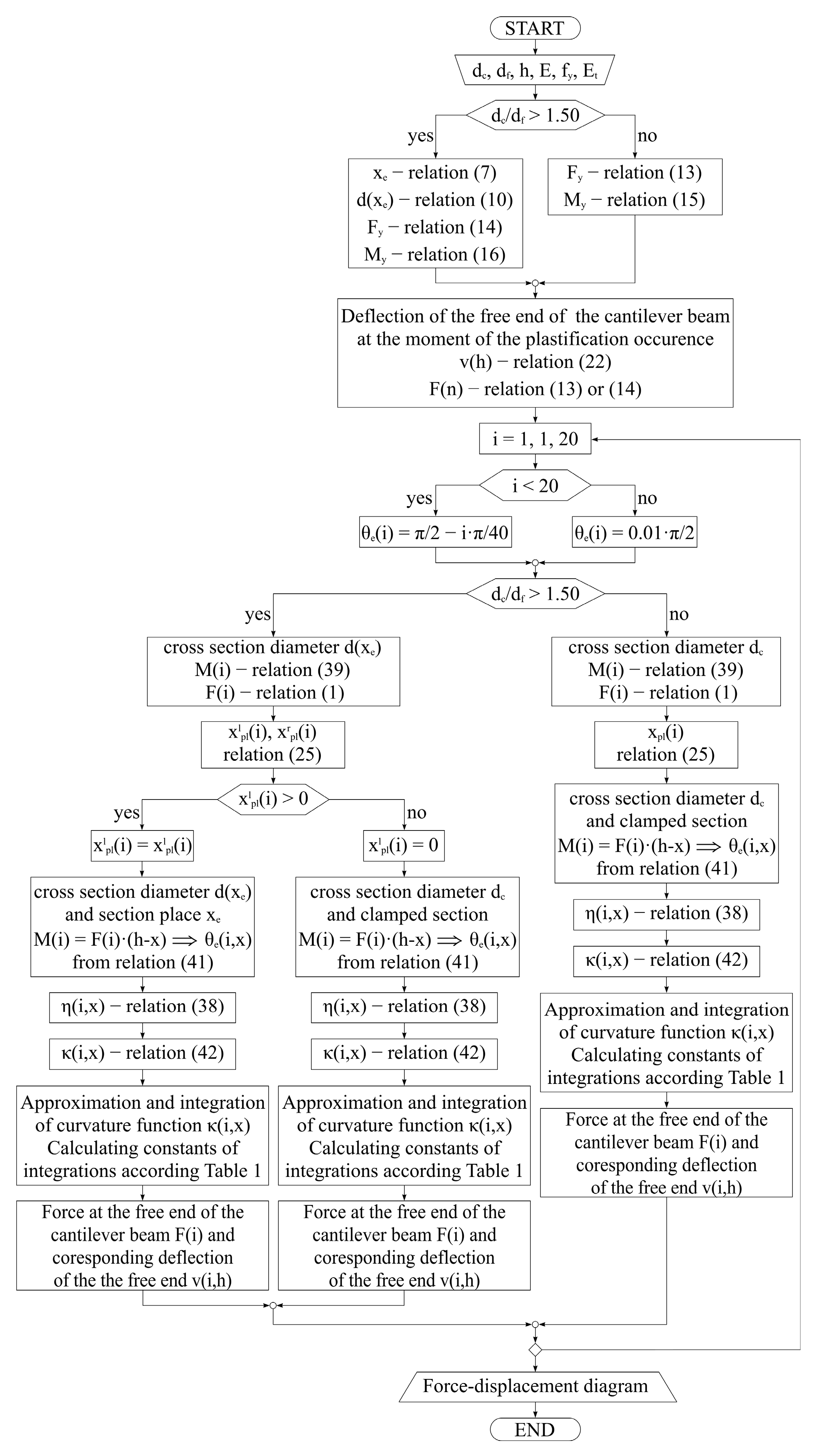
A flow chart of the semi-analytical algorithm is shown in Figure 4.

3. Validation of the Proposed Semi-Analytical Solution

Validation of the proposed semi-analytical solution for the elastoplastic strain hardening deflection of the cantilever beam with a linearly variable circular cross-section loaded by the shear force at the free end will be conducted using the results of the experimental testing of the innovative steel seismic energy dissipation device components [26] and the results of the numerical analysis based on the finite element method and software package Abaqus/Standard.

3.1. Validation of the Proposed Semi-Analytical Solution Regarding Experimental Results

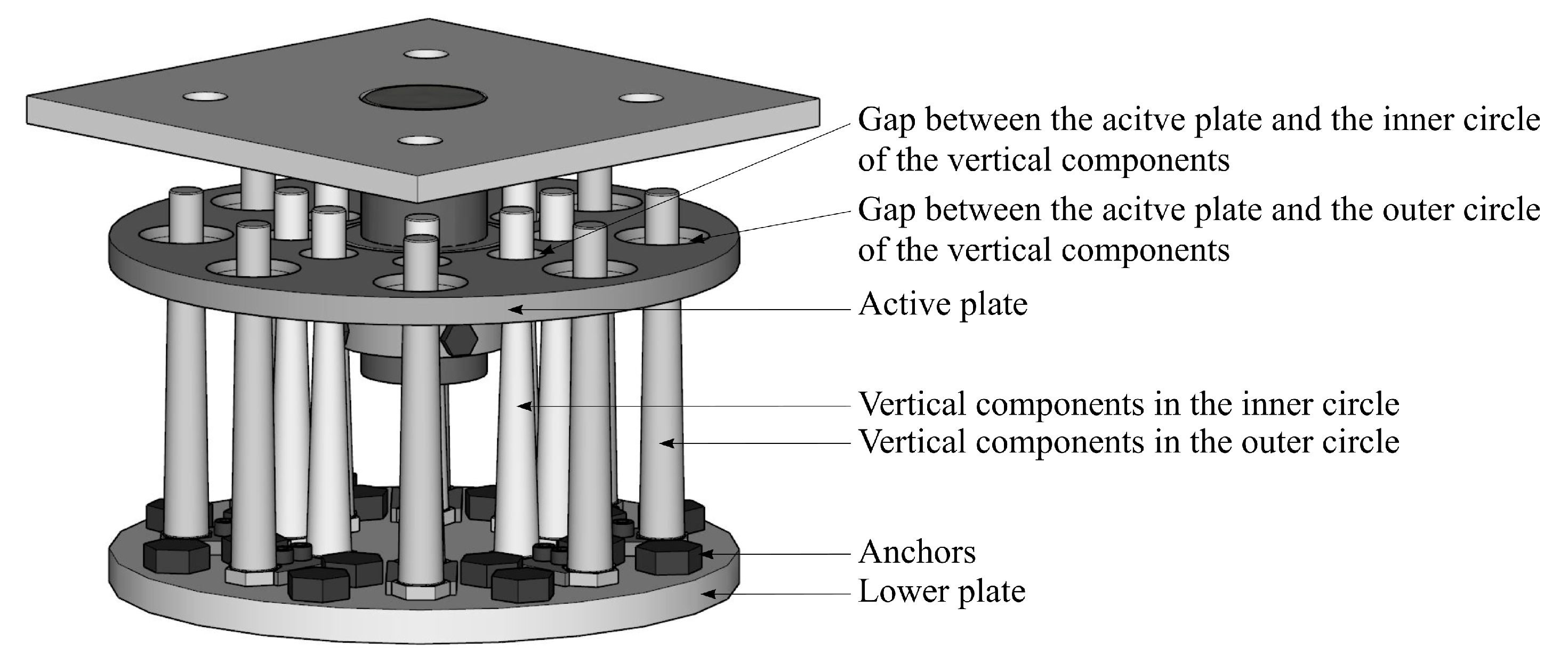
The innovative steel seismic energy dissipation device (Figure 5) consists of one lower plate anchored into the structure foundations, several vertical components with circular cross-section variable across their length which are fixed into the lower plate, and one active plate which is indirectly connected to the isolated structure. During an earthquake, the active plate moves, and, after annealing the gaps, bends the vertical components which then absorb seismic energy, entering the inelastic range of the material.
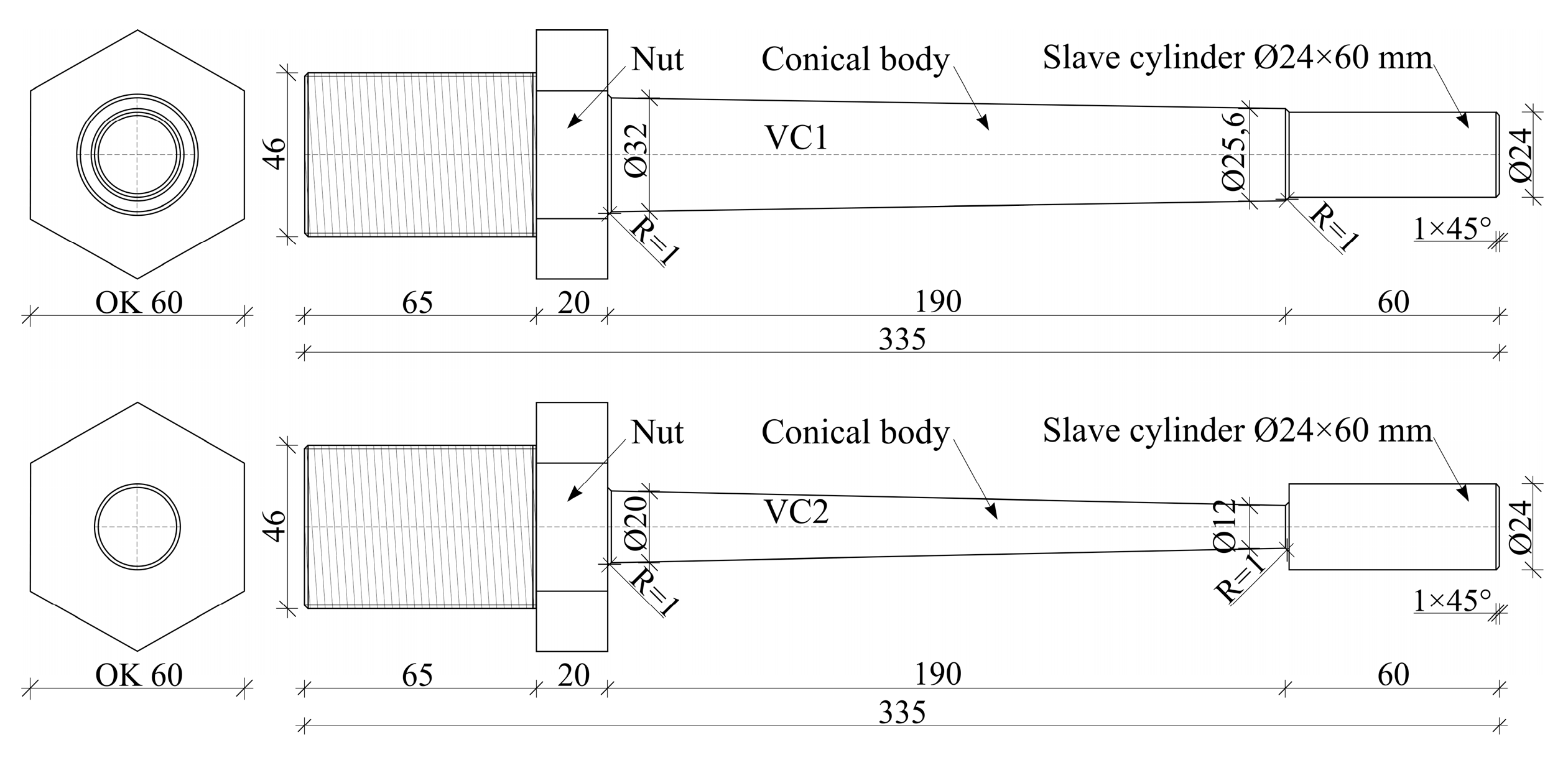
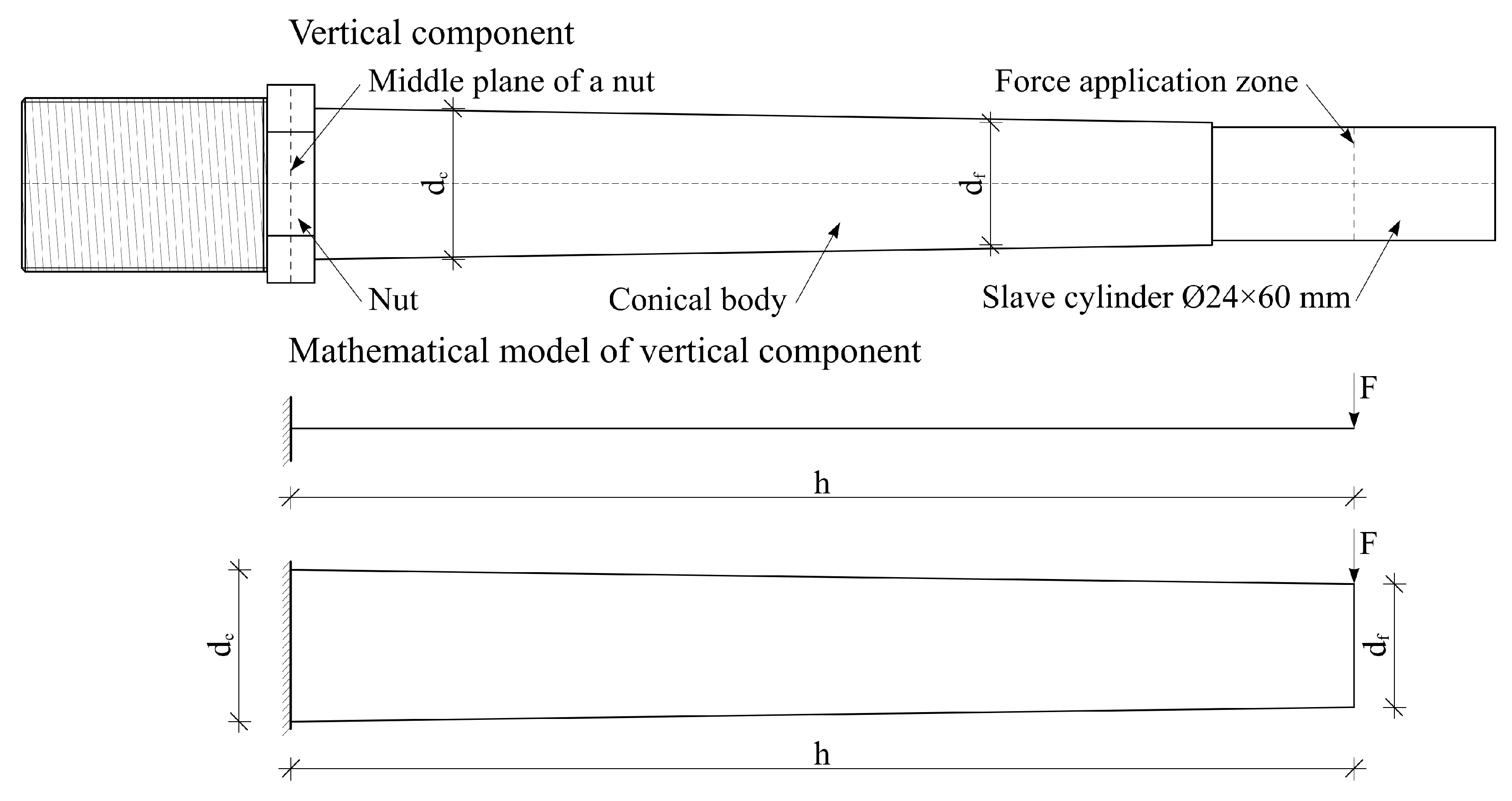
Within the innovative project, the experimental testing of the vertical components with different geometric characteristics was realized, and force–displacement relationships were defined [26]. The tested vertical components are cantilever beams with linearly variable cross-section. The height of the conical body of the vertical components is 190 mm. Two combinations of the cross-sections diameter of the conical body were analyzed: VC1—bottom diameter 32 mm and top diameter 25.6 mm; VC2—bottom diameter 20 mm and top diameter 12 mm. At the top of the vertical components, a slave cylinder Ø 24 × 60 mm was introduced in order to accept the external load and transfer it to the conical body minimizing stress concentrations in the zone of force application. The prototypes of vertical components were fixed into the testing equipment via nut and thread on the base of the vertical component (Figure 6).
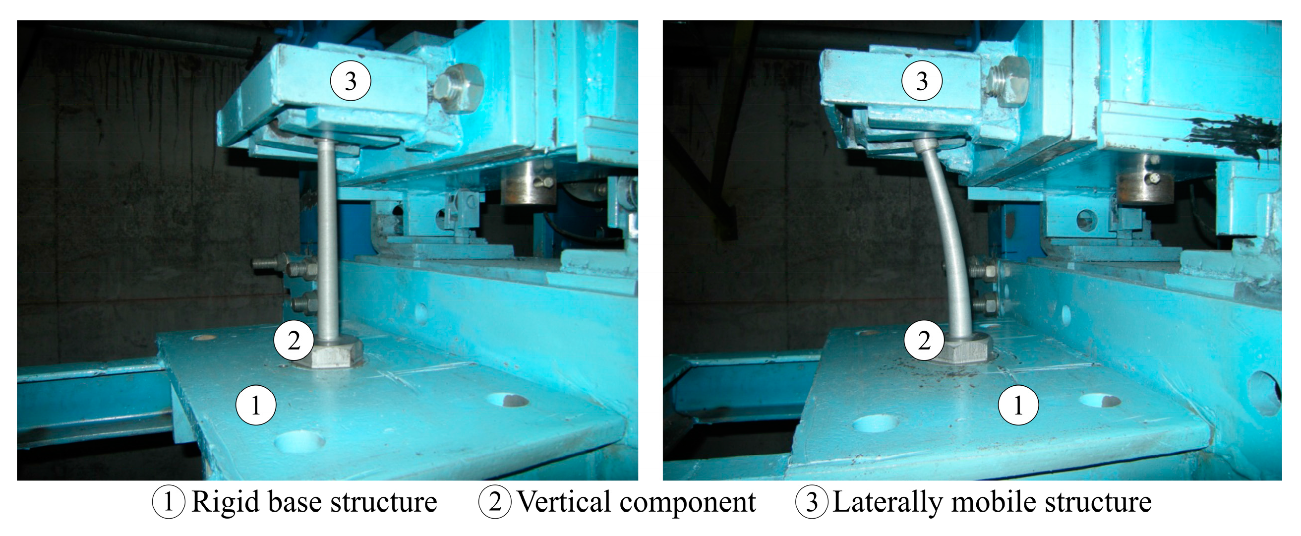
The vertical components were made of steel C45 [31], which had been chosen as suitable for the aspects of ductility, toughness, and fatigue resistance. The mechanical properties of the steel material are presented in subsequent text. A specific test platform was created for the experiment, consisting of two basic segments: rigid base structure, which the vertical components were fixed to, and a laterally mobile structure connected to a horizontal hydraulic actuator for displacement application. The laterally mobile structure is constructed in a way to not constrain the slave cylinder at the top of the vertical components. The initial position of the vertical component and characteristic deformed configuration during the test are shown in Figure 7.
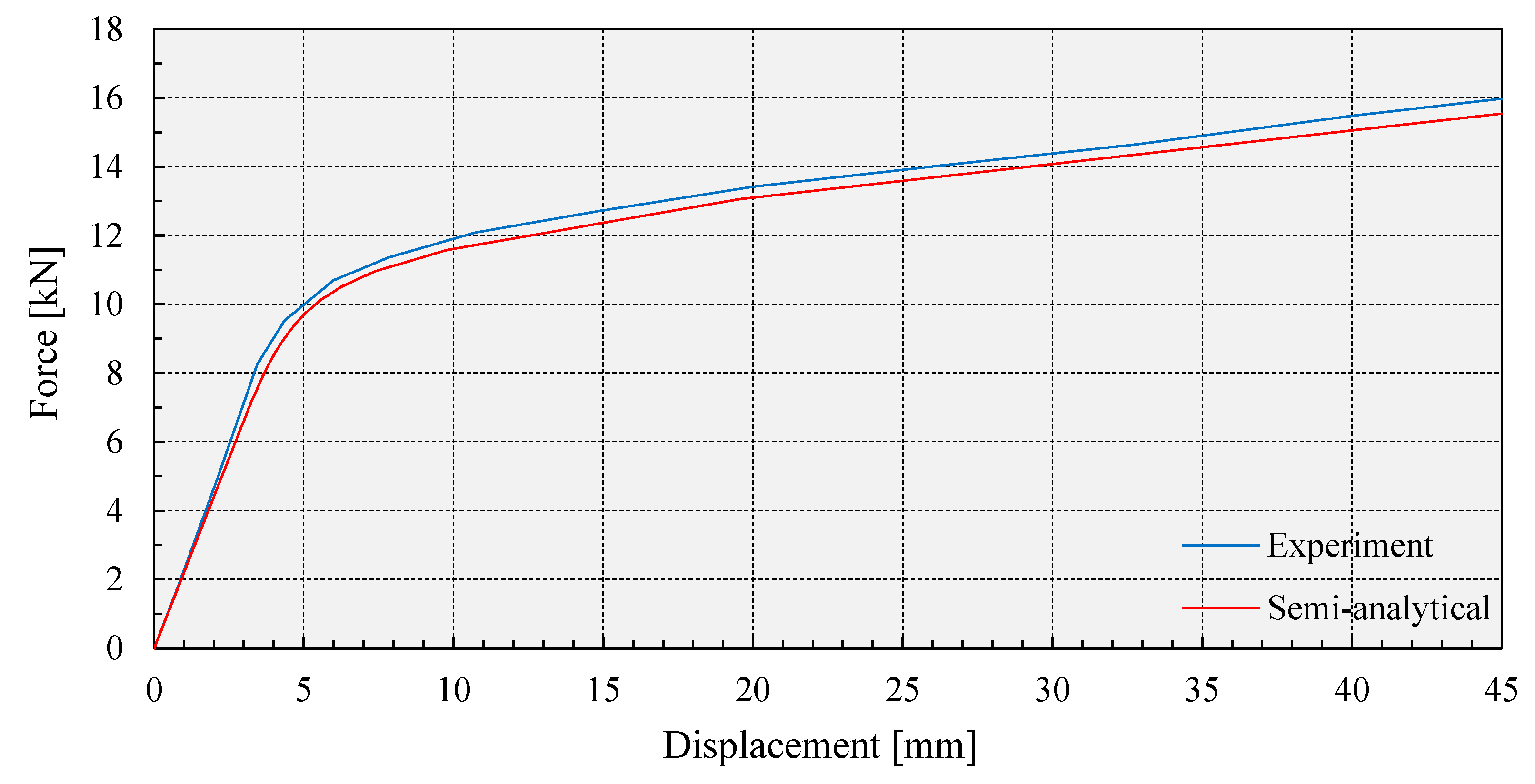
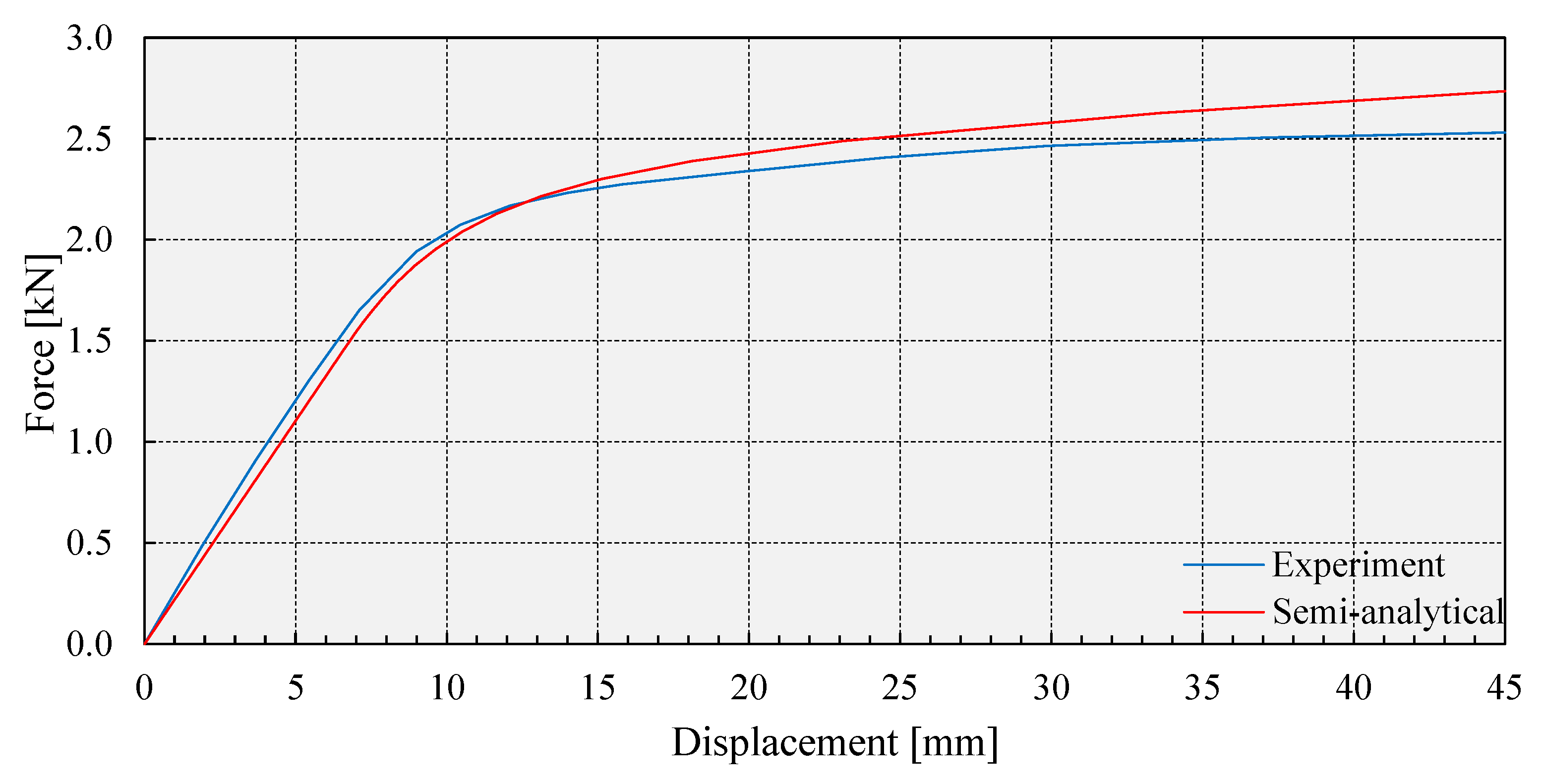
During the experimental testing of the vertical components, the displacement was applied in a controlled so-called “time mode” with an increment of 1 mm/s. The displacement in the direction of the horizontal actuator piston was monitored using an electronic displacement transducer (LVDT), while simultaneously monitoring the force increase via an electronic dynamometer. For recording signals, an adequate multi-channel measuring-acquisition system connected to a personal computer was used, where rate sampling was 10 s−1. Automatic data processing was done in order to obtain force–displacement diagrams of the tested vertical components. The force–displacement diagrams obtained from testing are presented in Figure 8 and Figure 9.
With the aim of defining a mathematical model and an application of the semi-analytical solution for the vertical components, some idealizations of the problem are introduced. It is assumed that the vertical component is clamped into a rigid base structure of the test equipment. Therefore, in the contact between the nut and rigid base structure of the test equipment, there is no rotation of the nut, but the upper surface of the nut is free. Considering this, in the mathematical model, it is adopted that the vertical component is clamped at the level of the middle plane of the nut. The zone of the load application is in the middle plane of the slave cylinder at the top of the vertical component. The upper part of the slave cylinder from the load application zone toward the free end does not significantly affect the stress-strain state of the vertical component; therefore, that part is neglected. The laterally mobile structure of the test equipment does not constrain displacements and rotations of the vertical component cross-section at the load application zone. Therefore, in the mathematical model, it is adopted that the vertical component has a free end in the load application zone. Based on everything aforementioned for the mathematical model of the vertical component, the cantilever beam with span h is adopted. The span of the cantilever beam is equal to the sum of the half of the nut thickness, length of the conical body of the vertical component, and the length of the slave cylinder to the load application zone. The mathematical model is simplified by neglecting the cross-section of the nut and the slave cylinder, so the cantilever beam is treated as a beam of circular cross-section linearly variable along the beam axis. Therefore, the diameter of the cross-section at the clamped end is dc, while the diameter of the cross-section at the free end is df (Figure 10).
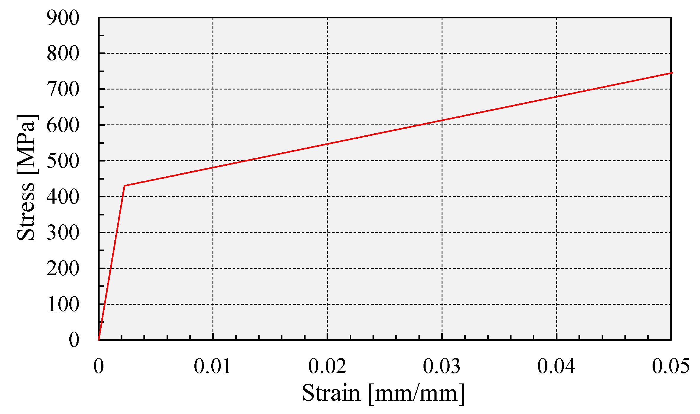
The material input data for the selected steel C45 are as follows: modulus of elasticity E = 190 GPa, Poisson’s ratio ν = 0.30, yield stress fy = 430 MPa, ultimate stress fu = 650–800 MPa, ultimate strain 16%. In the analysis, the nonlinear behavior of the steel material is modelled via bilinear stress-strain relation. After the yield point, the stress is proportional to strain by tangent modulus Et = 6600 MPa (Figure 11).
With such defined geometric and material parameters of the vertical components, the semi-analytical solution is conducted in accordance with the assumptions presented in Section 2. Force–displacement diagrams are shown in Figure 8 and Figure 9 and compared to the experimental results. It can be concluded that the results obtained via semi-analytical solution are in good correlation with the experimental ones. The values of the shear forces at the displacement of the 45 mm, elastic stiffness, and post-yield stiffness, for the experimental test and for semi-analytical solution as well, are shown in Table 2. Based on the comparative analysis of the results, it can be concluded that semi-analytical solution is validated by the experiment, considering that the difference between semi-analytical and experimental results is less than 10%.

3.2. Validation of the Proposed Semi-Analytical Solution Regarding Numerical Results

A numerical analysis of the elastoplastic bending of the cantilever beam with linearly variable circular cross-section is conducted via the application of the finite element method and software package Abaqus/Standard. The main aim was to validate the results of the semi-analytical solution presented in the paper using the numerical results. Two cases with different cross-sections diameter ratio were analyzed: dc/df = 30/24 mm; dc/df = 30/15 mm. The analysis covers two variants of the span of the cantilever beam: h = 200 mm and h = 500 mm. Besides the material model of steel C45 described in the previous section, the analysis was also conducted in the case when the yield stress of the material was fy = 350 MPa and the tangent modulus was Et = 2000 MPa. The aim was to examine the sensitivity of the proposed semi-analytical solution regarding the physical–mechanical characteristics of the material. All model data are systematized in Table 3.
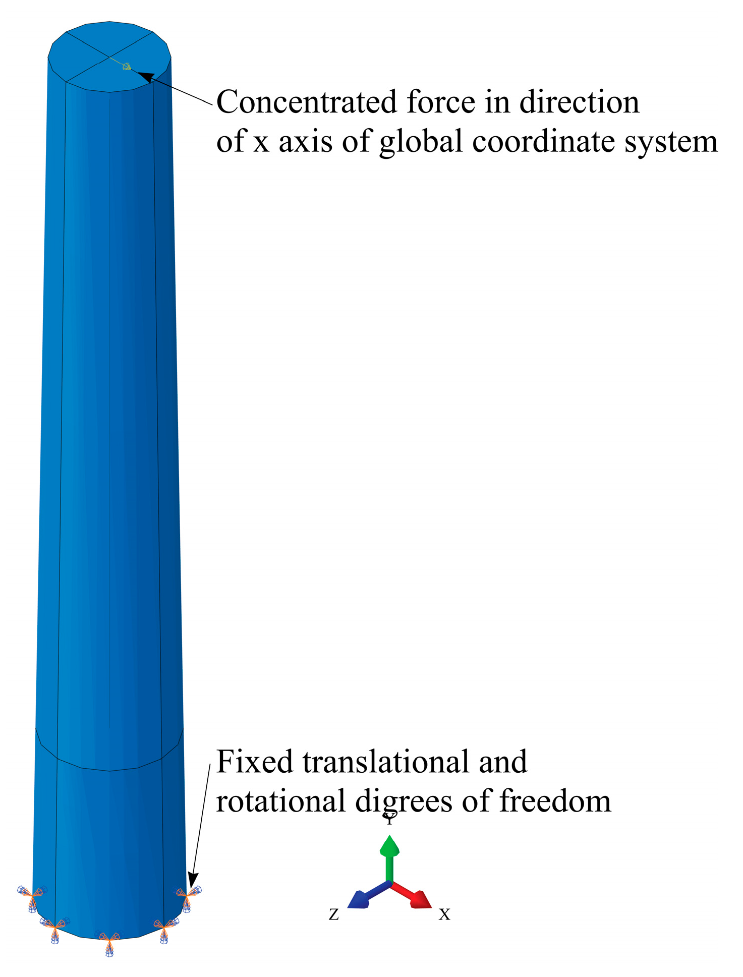
In order to define the fixed support in the numerical model, all degrees of freedom in the plane of the cantilever beam cross-section are constrained (Figure 12). Monotonously increasing the load at the free end of the cantilever beam is defined as a concentrated force in the center of gravity of the cross-section in the direction of the x axis of the global coordinate system (Figure 12).
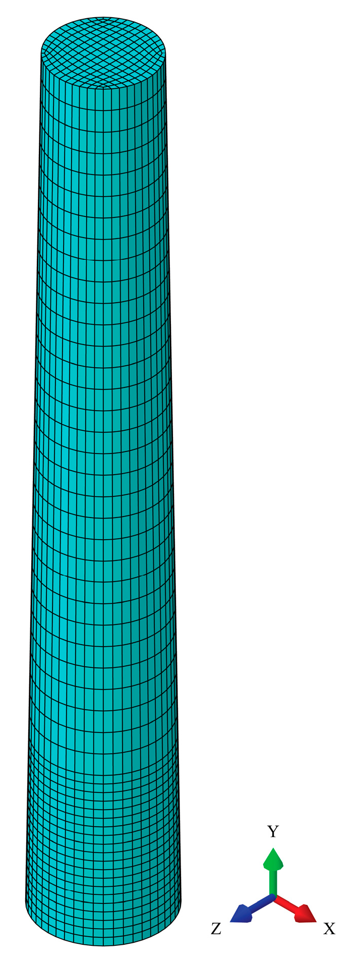
Finite element mesh convergence was done for the model C1 in order to obtain the optimal element type and mesh density. The model was meshed with solid hexahedral elements with three translator degrees of freedom per node, which is suitable for stress-strain analysis of the continuum. Tetrahedral elements were not analyzed because they are usually overly stiff and should be avoided whenever possible. When the bending deformation is dominant and solid elements with linear shape functions are applied, large shear stiffness can occur, which is not realistic. This phenomenon is known as “shear locking” and it can be prevented by increasing the number of finite elements, using solid elements with quadratic shape functions, or using reduced integration [32,33]. Therefore, in this study, solid elements with reduced integration for determining elements of the stiffness matrix are applied. In the mesh sensitivity analysis, two variants of mesh density are analyzed. In the first variant, the number of divisions of the circular cross-section of the cantilever is 48, while the size of the finite elements along the longitudinal axis of the cantilever beam is 5 mm. In the fixed support zone, which takes 20% of the length of the cantilever beam, the finite element mesh is finer where the element size is 2 mm. In the second variant, the number of divisions of the circular cross-section of the cantilever is 64 and the size of the finite elements along the longitudinal axis is 3.5 mm, while in the fixed support zone it is 1.5 mm. For each of these variants, the number of nodes per element varies. Namely, Abaqus/Standard element library offers first-order solid elements with 8 nodes and second-order solid elements with 20 nodes [32], and both of these elements are covered in the mesh sensitivity analysis. Taking everything into account, four cases of finite element mesh were analyzed. As a subject of the mesh convergence analysis, the value of the displacement of the free end of the cantilever beam due to the 10 kN intensity of the external load is adopted. Spatial discretization error of the numerical analysis is estimated through a normalized von Mises stress error indicator [32] for the elements in the fixed support zone. All cases for mesh sensitivity analysis, as well as the results, are systematized in Table 4.
Based on the results of the mesh sensitivity analysis, one may conclude that the mesh convergence is achieved by taking into account that the differences of displacement of the free end of the cantilever beam due to 10 kN intensity of the external load are around 3%. Analyzing the value of the normalized von Mises stress error indicator, it can be concluded that the numerical error due to spatial discretization error is negligible and does not have an influence on the results. In further numerical analyses, all cantilever beam models are meshed with 8-node solid finite elements with reduced integration, where the mesh density of case I of the mesh sensitivity analysis was adopted, since it is favorable regarding the other cases from the aspect of required computer resources. Regardless of the same mesh density, there are differences in the number of elements, nodes, and degrees of freedom between analyzed cantilever beam models (Table 5). These differences are consequences of different geometry of the analyzed cantilever beam models. The finite element mesh of the characteristic cantilever beam model is shown in Figure 13.
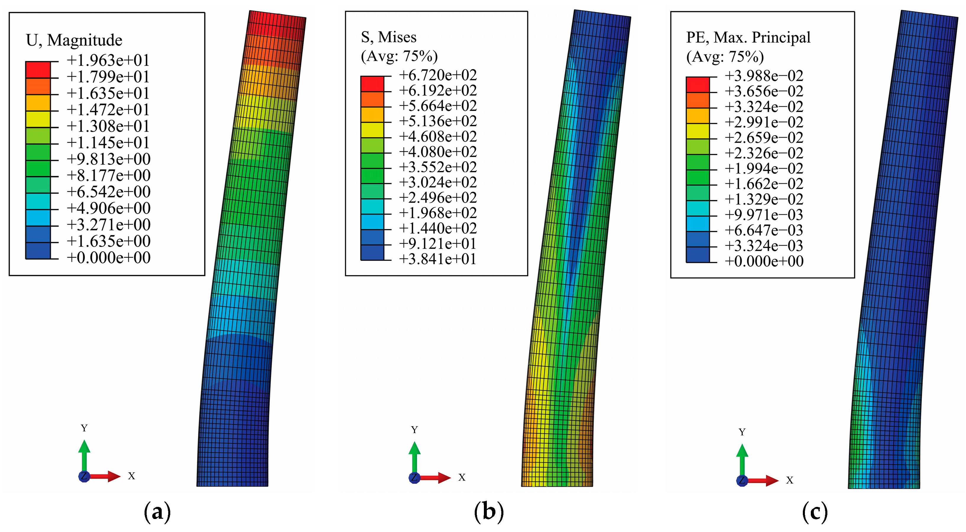
The stress-strain analysis is described for the model C1, chosen as a representative sample. Total deformations, von Mises stresses, and maximum principal plastic strains are presented in Figure 14, all for the external load intensity of 12 kN. Under this load von Mises stress is greater than yield stress. Therefore, plastic strains occur in the region of the fixed support and propagate to the free end of the cantilever beam. Taking into account discussion presented in Section 2 and the fact that the cross-sections diameter ratio of this model is lower than 1.50, such a propagation of the plastic strains is expected. It is worth mentioning that stress concentration occurs in a small region of the load application point, but it does not have an influence on the overall stress-strain state of the cantilever beam. The stress concentrations in the numerical analysis are not the subject of this paper, so they will not be further explained. The purpose of this numerical analysis is the validation of the proposed semi-analytical solution, which will be done based on the force–displacement relationships of the analyzed models.
The force–displacement relationship obtained by numerical analysis, and the results based on the proposed semi-analytical solution, are shown side-by-side in Figure 15. For the deflection limit of the free end of the cantilever beam, the value of 0.15 h was adopted, which is 30 mm for h = 200 mm and 75 mm for h = 500 mm. The values of the shear forces at the limit displacements, as well as the elastic stiffness and post-yield stiffness, are shown in Table 6. Based on the comparative analysis of the results, it can be concluded that the semi-analytical solution is satisfactorily validated by numerical results, considering that the difference between the semi-analytical and FEM results, in cases of force at limit displacement and elastic stiffness, is less than 5%. It should be mentioned that post-yield stiffness differences are less than 10%, which may be considered as significant, but taking into account that this stiffness is a small value, obtained differences are expected and can be taken as satisfying.

4. Conclusions

Cantilever beams with linearly variable circular cross-section along the beam axis are often applied in engineering practice. The solution for the elastoplastic deflection of such cantilever beams suitable for practical use has not been developed, to the authors’ best knowledge. A semi-analytical solution for determining the deflection of the cantilever beam with linearly variable circular cross-section loaded by shear force at the free end was presented in this paper. A semi-analytical solution was developed for the beams made of homogenous and isotropic materials, which can be described via the bilinear elastoplastic strain hardening model. Based on the results presented in this paper, general conclusions can be summarized as follows:
  • it is confirmed that the Bernoulli–Euler formula grants satisfying results for the analysis of the deflection of the cantilever beam in the elastic regime, while in the plastic regime the differential equation of beam bending has no solution in the closed form; therefore, the problem needs to be solved via incremental analysis;
  • the results of the proposed semi-analytical solution are in good correlation with the experimental results of two models of vertical components of a seismic energy dissipation device;
  • the results of the proposed semi-analytical solution are in good correlation with the numerical results of several cantilever beam models, where the cross-section diameter, beam span, and mechanical characteristics of material vary;
  • taking into account the above-mentioned conclusions, the proposed semi-analytical solution is considered as validated;
  • the proposed semi-analytical solution is a simple method for application in practical engineering.
Future research can be directed toward developing a solution for different elastoplastic material behavior models and different load types along the axis of the cantilever beam. Furthermore, in the case of significant axial load, an elastoplastic stability analysis of such elements would be very useful. The solution presented in this paper can serve as a good basis for further research.

Author Contributions

Conceptualization, A.Z. and M.T.-M.; methodology, A.Z.; software, A.Z. and T.V.; validation, A.Z., M.T.-M. and T.V.; formal analysis, A.Z., M.T.-M. and D.Z.; investigation, A.Z. and D.Z.; resources, A.Z. and M.T.-M.; data curation, A.Z.; writing—original draft preparation, A.Z.; writing—review and editing, A.Z., M.T.-M. and T.V.; visualization, A.Z. and D.Z.; supervision, M.T.-M., D.Z. and T.V.; project administration, A.Z. All authors have read and agreed to the published version of the manuscript.

Funding

The experimental part of this research was funded by the Innovation Fund of the Republic of Serbia. The APC was funded by the authors.

Institutional Review Board Statement

Not applicable.

Informed Consent Statement

Not applicable.

Data Availability Statement

The data presented in this study are available on request from the corresponding author.

Conflicts of Interest

The authors declare no conflict of interest. The funder had no role in the design of the study; in the collection, analysis or interpretation of data; in the writing of the manuscript; or in the decision to publish the results.

List of Symbols

EYoung’s modulus
Ettangent modulus
Fforce
Fyyield force
Izcross-section moment of inertia related to the z axis
Keelastic stiffness
Kypost-yield stiffness
Mbending moment
Mmaxmaximum bending moment
Myyield bending moment
bwidth of elemental integration area
ddiameter of circular cross-section
dcdiameter of circular cross-section at the clamped end of the cantilever beam
dfdiameter of circular cross-section at the free end of the cantilever beam
fuultimate stress of material
fyyield stress of material
hlength of the cantilever beam
rradius of circular cross-section
vdeflection of the cantilever beam
veldeflection of the cantilever beam in the elastic regime
vleldeflection of the elastic region from the fixed support to the boundary between the elastic and the plastic region of the cantilever beam
vreldeflection of the elastic region from the boundary between the elastic and the plastic region to the free end of the cantilever beam
vpldeflection of the cantilever beam in the plastic regime
xeposition of the critical cross-section
xpboundary between the elastic and the plastic region of the cantilever beam
xplboundary between the elastic and the plastic region from the fixed support to critical cross-section of the cantilever beam
xprboundary between the elastic and the plastic region from the critical cross-section to the free end of the cantilever beam
ymaxmaximum distance of fibers from neutral axis
εstrain
εplplastic strain
εyyield strain
ηcross-section part from neutral axis in elastic regime
θangle in polar coordinate system
θeangle defining elastic part of the cross-section
κcurvature
νPoisson’s ratio
πArchimedes’ constant
σnormal stress
σmaxmaximum normal stress
φslope of the cantilever beam
φelslope of the cantilever beam in the elastic regime
φlelslope of the elastic region from the fixed support to the boundary between the elastic and the plastic region of the cantilever beam
φdelslope of the elastic region from the boundary between the elastic and the plastic region to the free end of the cantilever beam
φplslope of the cantilever beam in the plastic regime

References

  1. Levien, R. The Elastica: A Mathematical History; Technical Report No. UCB/EECS-2008-103, Electrical Engineering and Computer Sciences; University of California: Berkeley, CA, USA, 2008. [Google Scholar]
  2. Bisshopp, K.E.; Drucker, D.C. Large deflection of cantilever beams. Q. Appl. Math. 1945, 3, 272–275. [Google Scholar] [CrossRef] [Green Version]
  3. Banerjee, A.; Bhattacharya, B.; Mallik, A.K. Large deflection of cantilever beams with geometric non-linearity: Analytical and numerical approaches. Int. J. Non Linear Mech. 2008, 43, 366–376. [Google Scholar] [CrossRef]
  4. Lee, S.Y.; Kuo, Y.H. Deflection and Stability of Elastically Restrained Nonuniform Beam. J. Eng. Mech. 1991, 117, 674–692. [Google Scholar] [CrossRef]
  5. Dong, L.; Alotaibi, A.; Mohiuddine, S.A.; Atluri, S.N. Computational Methods in Engineering: A Variety of Primal & Mixed Methods, with Global & Local Interpolations, for Well-Posed or Ill-Posed BCs. Comput. Model. Eng. Sci. 2014, 99, 1–85. [Google Scholar] [CrossRef]
  6. Lee, J.K.; Lee, B.K. Elastica of Non-Prismatic and Nonlinear Elastic Cantilever Beams unde Combined Loading. Appl. Sci. 2019, 9, 877. [Google Scholar] [CrossRef] [Green Version]
  7. Latalski, J.; Zulli, D. Generalized Beam Theory for Thin-Walled Beams with Curvilinear Open Cross-Sections. Appl. Sci. 2020, 10, 7802. [Google Scholar] [CrossRef]
  8. Yu, T.X.; Johnson, W. The plastica: The large elastic-plastic deflection of a strut. Int. J. Non-Linear Mech. 1982, 17, 195–209. [Google Scholar] [CrossRef]
  9. Xiaoqiang, W.; Tongxi, Y. The Complete Process of Large Elastic-Plastic Deflection of a Cantilever. Acta Mech. Sin. 1986, 2, 333–341. [Google Scholar] [CrossRef]
  10. Gere, J.; Timoshenko, S. Mechanics of Materials, 4th ed.; PWS: Boston, MA, USA, 1997. [Google Scholar]
  11. Štok, B.; Halilovič, M. Analytical solutions in elasto-plastic bending of beams with rectangular cross section. Appl. Math. Model. 2009, 33, 1749–1760. [Google Scholar] [CrossRef]
  12. Ghosh, S.; Roy, D. Numerical-Analytic Form of the Adomian Decomposition Method for Two-Point Boundary Value Problems in Nonlinear Mechanics. J. Eng. Mech. 2007, 133, 1124–1133. [Google Scholar] [CrossRef]
  13. Huang, X.; Wang, B.; Lu, G.; Yu, T.X. Large deflection of elastoplastic, non-linear strain-hardening cantilevers. Proc. Inst. Mech. Eng. Part C J. Mech. Eng. Sci. 2001, 216, 433–446. [Google Scholar] [CrossRef]
  14. Liu, J.H.; Atkins, A.G.; Pretlove, A.J. The effect of inclined loads on the large deflection behaviour of elastoplastic work-hardening straight and pre-bent cantilevers. Proc. Inst. Mech. Eng. Part C J. Mech. Eng. Sci. 1995, 209, 87–96. [Google Scholar] [CrossRef]
  15. Solano-Carrillo, E. Semi-exact solutions for large deflections of cantilever beams of non-linear elastic behaviour. Int. J. Non-Linear Mech. 2009, 44, 253–256. [Google Scholar] [CrossRef]
  16. Kang, Y.-A.; Li, X.-F. Bending of functionally graded cantilever beam with power-law non-linearity subjected to an end force. Int. J. Non-Linear Mech. 2009, 44, 696–703. [Google Scholar] [CrossRef]
  17. Pascon, J.P. Numerical analysis of highly deformable elastoplastic beams. Lat. Am. J. Solids Struct. 2015, 12, 1595–1615. [Google Scholar] [CrossRef] [Green Version]
  18. Pandit, D.; Thomas, N.; Patel, B.; Srinivasan, S.M. Finite Deflection of Slender Cantilever with Predefined Load Application Locus using an Incremental Formulation. Comput. Mater. Contin. 2015, 45, 127–144. [Google Scholar] [CrossRef]
  19. Pandit, D.; Srinivasan, S.M. Numerical analysis of large elasto-plastic deflection of constant curvature beam under follower load. Int. J. Non-Linear Mech. 2016, 84, 46–55. [Google Scholar] [CrossRef]
  20. Romano, F.; Ganduscio, S.; Zingone, G. Elastoplastic Deflection for Prismatic and Nonprismatic Beams. J. Eng. Mech. 1993, 119, 1117–1135. [Google Scholar] [CrossRef]
  21. Milligan, R. Moment-Strain Relationships in Elastic-Plastic Bending of Beams; Report No. ARLCB-TR-81025, US Army Armament Research & Development Command; Large Caliber Wapon Systems Laboratory: New York, NY, USA, 1981. [Google Scholar]
  22. Daunys, M.; Rimovskis, S. Analysis of circular cross-section element, loaded by static and cyclic elastic-plastic pure bending. Int. J. Fatigue 2006, 28, 211–222. [Google Scholar] [CrossRef]
  23. Rimovskis, S.; Sabaliauskas, A. Analysis of Rectangular and Circular Cross-section Power Hardening Elements Under Pure Bending. Int. J. Mater. Eng. 2012, 2, 84–89. [Google Scholar] [CrossRef] [Green Version]
  24. Abdallah, S.; Rees, D. Elastic-plastic bending analysis of a circular cross section. In Proceedings of the 7th International Colloquium on Performance, Protection and Strengthening of Structures under Extreme Loading and Events, Whisler, BC, Canada, 16–17 September 2019. [Google Scholar]
  25. Gohari, S.; Sharifi, S.; Vrcelj, Z. New explicit solution for static shape control of smart laminated cantilever piezo-composite-hzbrid plates/beams under thermo-electro-mechanical loads using piezoelectric actuators. Compos. Struct. 2016, 145, 89–112. [Google Scholar] [CrossRef]
  26. Zlatkov, D.; Projektinženjering Tim Ltd. Seismo-Safe 2G3-GOSEB Buidling System, Project ID 476, Report No. 1–4; Innovation Fund of the Republic of Serbia: Niš, Serbia, 2015. [Google Scholar]
  27. Ristić, D.; Ristić, J.; Zlatkov, D. Adaptivni Sistem za Seizmičku Zaštitu Objekata Zgrada od Dejstva Jakih Zemljotresa Putem Konstruktivno Obezbeđene Globalne Optimizacije Seizmo-Energetskog Balansa. Republic of Serbia Patent 57554, 31 October 2018. [Google Scholar]
  28. MacCullough, G.H. An Experimental and Analytical Investigation of Creep in Bending. J. Appl. Mech. 1933, 1, 55–60. [Google Scholar] [CrossRef]
  29. Syed, J.I.A.; Kumar, P.; Jayaram, V. Creep of Metallic Materials in Bending. JOM 2019, 71, 3565–3583. [Google Scholar] [CrossRef]
  30. Hamming, R.W. Numerical Methods for Scientists and Engineers, 2nd ed.; Dover Publications Inc.: New York, NY, USA, 1973. [Google Scholar]
  31. EN ISO 683-1:2018; Heat-Treatable Steels, Alloy Steels and Free-Cutting Steels—Part 1: Non-Alloy Steels for Quenching and Tempering. European Committee for Stadardization: Brussels, Belgium, 2018.
  32. Abaqus Theory Manual; Dassault Systèmes Simulia Corporation: Providence, RI, USA, 2014.
  33. Zienkiewicz, O.; Taylor, R.L.; Zhu, J.Z. The Finite Element Method: Basis and Fundamentals, 6th ed.; Elsevier: Holland, The Netherlands, 2005; pp. 398–404. [Google Scholar]
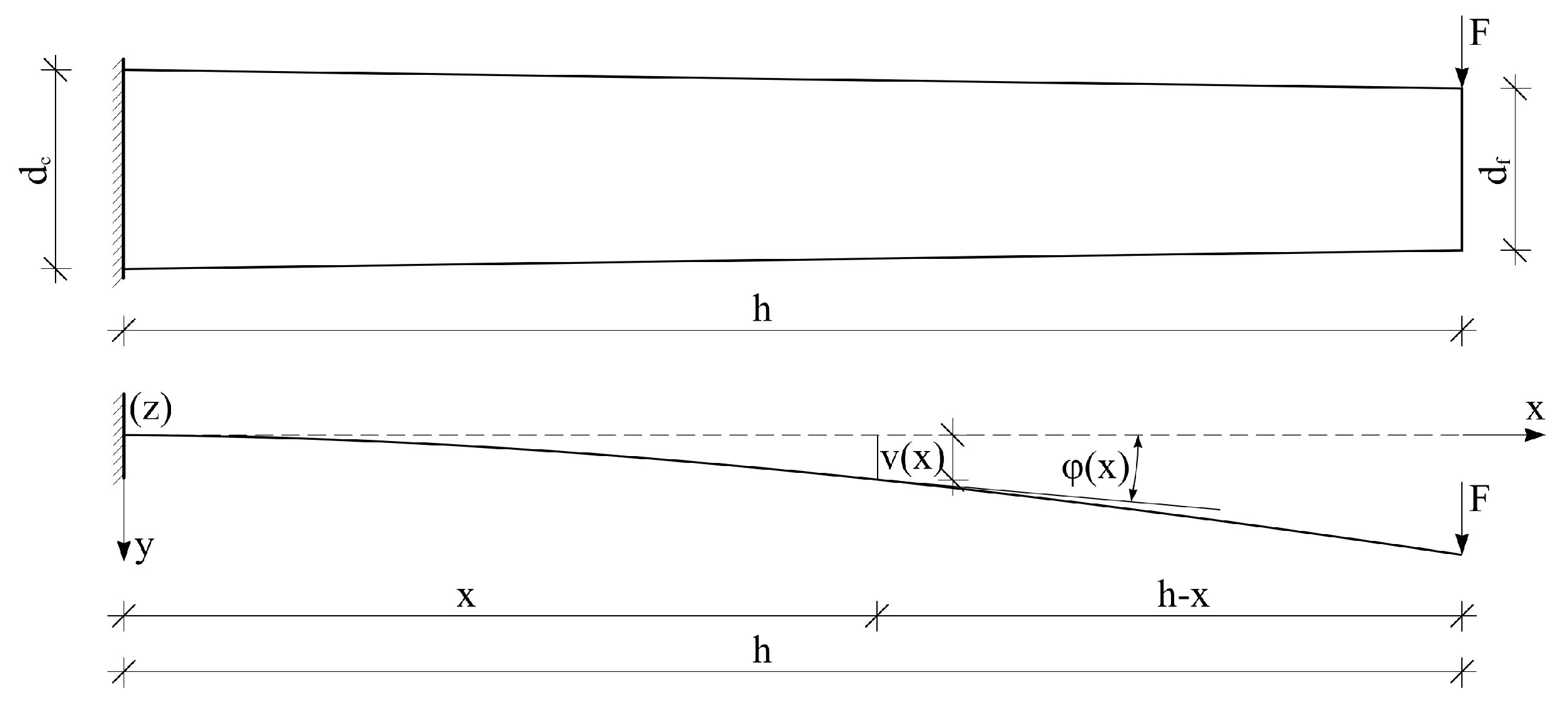
Figure 1. A mathematical model and characteristic deformation of the cantilever beam.
Applsci 12 05439 g001
Figure 2. The stress-strain state of the cantilever beam in the plastic regime of the material behavior.
Applsci 12 05439 g002
Figure 3. The elemental integration area.
Applsci 12 05439 g003
Figure 4. A flow chart of the semi-analytical algorithm.
Applsci 12 05439 g004
Figure 5. The geometry and components of the innovative steel seismic energy dissipation device.
Applsci 12 05439 g005
Figure 6. The geometry of the tested vertical components of the energy dissipation device.
Applsci 12 05439 g006
Figure 7. An experimental test setup of vertical components of the energy dissipation device.
Applsci 12 05439 g007
Figure 8. A force–displacement diagram for VC1.
Applsci 12 05439 g008
Figure 9. A force–displacement diagram for VC2.
Applsci 12 05439 g009
Figure 10. A mathematical model for the application of the semi-analytical solution for the force–displacement relationship of the vertical component of the energy dissipation device.
Applsci 12 05439 g010
Figure 11. A material model of the steel material C45 for the semi-analytical solution.
Applsci 12 05439 g011
Figure 12. The geometry and boundary conditions of the cantilever beams.
Applsci 12 05439 g012
Figure 13. The finite element mesh of the cantilever beam.
Applsci 12 05439 g013
Figure 14. The finite element method analysis results for model C1: (a) total deformation; (b) von Mises stress; (c) maximum principal plastic strain.
Applsci 12 05439 g014
Figure 15. Force–displacement diagrams for cantilever beam models: (a) C1; (b) C2; (c) C3; (d) C4; (e) C5; (f) C6.
Applsci 12 05439 g015
Table 1. The boundary and continuity conditions.
dc/df≤1.50>1.50
Cross-Section at Clamped EndPlastifiedElasticPlastified
Boundary conditions φ pl ( 0 ) = 0
v pl ( 0 ) = 0
φ el l ( 0 ) = 0
v el l ( 0 ) = 0
φ pl ( 0 ) = 0
v pl ( 0 ) = 0
Continuity conditions φ pl ( x p ) = φ el ( x p )
v pl ( x p ) = v el ( x p )
φ pl ( x p l ) = φ el l ( x p l )
v pl ( x p l ) = v el l ( x p l )
φ pl ( x p r ) = φ el r ( x p r )
v pl ( x p r ) = v el r ( x p r )
φ pl ( x p ) = φ el ( x p )
v pl ( x p ) = v el ( x p )
Where: φpl(x)—function of the slope of the plastic region of the cantilever beam, vpl(x)—deflection of the plastic region of the cantilever beam, φel(x)—function of the slope of the elastic region of the cantilever beam, vel(x)—deflection of the elastic region of the cantilever beam, φpl(xp), φel(xp)—slope values in the cross-section at the boundary between the plastic and the elastic region of the cantilever beam, vpl(xp), vel(xp)—deflection values of the cross-section at the boundary between the plastic and the elastic region of the cantilever beam, φlel(x)—function of the slope of the elastic region of the cantilever beam from the cross-section at the clamped end to the boundary between the elastic and the plastic region of the cantilever beam, vlel(x)—deflection of the elastic region of the cantilever beam from the cross-section at the clamped end to the boundary between the elastic and the plastic region of the cantilever beam, φrel (x)—function of the slope of the elastic region of the cantilever beam from the boundary between the elastic and the plastic region of the cantilever beam to the free end of the cantilever beam, vrel(x)—deflection of the elastic region of the cantilever beam from the boundary between the elastic and the plastic region of the cantilever beam to the free end of the cantilever beam, φpl(xlp), φpl(xrp), φlel(xlp), φrel(xrp)—values of the slope in the cross-sections at the boundary between the plastic and the elastic region of the cantilever beam, vpl(xlp), vpl(xrp), vlel(xlp), vrel(xrp)—values of the deflection in the cross-sections at the boundary between the plastic and the elastic region of the cantilever beam.
Table 2. Semi-analytical vs. experimental results for vertical components.
ModelVC1VC2
ResultsSemi-AnalyticalExperimentDifference [%]Semi-AnalyticalExperimentDifference [%]
Force [kN] at displacement of 45 mm 15.5515.982.772.742.538.30
Elastic stiffness Ke [kN/mm]2.181172.368998.610.216510.231226.79
Post-yield stiffness Ky [kN/mm]0.115700.116160.400.012050.011831.86
Table 3. The analyzed models of the cantilever beams.
Modeldc [mm]df [mm]h [mm]E [GPa]Et [MPa]fy [MPa]
C130242001906600430
C23024500
C33015200
C43015500
C530242002000350
C63024500
Table 4. A mesh sensitivity analysis.
CaseNumber of Divisions of the CircleSize of the FE * along the Cantilever BeamNumber of Nodes per FE *Displacement of the Free EndNormalized Mises Stress Error Indicator
I485 mm (2 mm)86.43 mm0.97%
II485 mm (2 mm)206.27 mm2.19%
III643.5 mm (1.5 mm)86.38 mm0.94%
IV643.5 mm (1.5 mm)206.23 mm1.29%
* FE stands for finite element.
Table 5. The number of elements, nodes, and degrees of freedom of the analyzed models of the cantilever beams.
ModelNumber of ElementsNumber of NodesNumber of Degrees of Freedom
C1998411,50134,503
C224,96028,42785,281
C38112959328,779
C420,28023,71171,133
C5998411,50134,503
C624,96028,42785,281
Table 6. Semi-analytical vs. numerical results for cantilever beams.
ModelForce at Limit Displacement [kN] Elastic Stiffness Ke [kN/mm]Post-Yield Stiffness Ky [kN/mm]
Semi
Analytical
FEMDifference [%]Semi
Analytical
FEMDifference [%]Semi
Analytical
FEMDifference [%]
C113.1913.431.822.263422.170844.260.110950.120258.38
C24.444.501.350.144860.143381.030.011200.012219.02
C39.839.931.021.404881.335425.200.068730.074658.61
C43.403.472.060.090590.088841.970.009060.009737.40
C59.219.664.892.242022.156253.980.041550.045228.83
C63.413.502.640.144270.143410.600.005320.005829.40
Publisher’s Note: MDPI stays neutral with regard to jurisdictional claims in published maps and institutional affiliations.