Article

Power Management for Connected EVs Using a Fuzzy Logic Controller and Artificial Neural Network

1
College of Automation Engineering, Nanjing University of Aeronautics and Astronautics, Nanjing 211106, China
2
College of Information Engineering, Nanjing University of Finance and Economics, Nanjing 210023, China
*
Author to whom correspondence should be addressed.
Appl. Sci. 2022, 12(1), 52; https://doi.org/10.3390/app12010052
Submission received: 26 November 2021 / Revised: 12 December 2021 / Accepted: 15 December 2021 / Published: 22 December 2021

Abstract

:
In recent years, the electric vehicles (EVs) power management strategy has been developed in order to reduce battery discharging power and fluctuation when an EV requires high and rapid discharging power due to frequent stop-and-go driving operations. A combination of lithium-ion battery and supercapacitor (SC) as the EV’s energy sources, known as a hybrid energy storage system (HESS), is a promising solution for fast discharging conditions. Effective power management to extensively utilize HESS can be developed if future power demand is accessible. A vehicular network as a typical form of the currently developed internet of things (IoT) has made future information obtainable by collecting information on surrounding data. This paper proposes a power management strategy for the HESS with the support of IoT. Since the obtained information from the vehicular network could not directly be used to improve HESS, a two-level control structure has been developed to perform future data prediction and power distribution. A fuzzy logic controller (FLC) is utilized in level one control structure to manage a HESS power split based on future information. Since FLC requires future information as a reference input, the future information is obtained by using an artificial neural network (ANN) in level two control structure. The ANN provides a direct prediction that could approximate the future power demand prediction with the assumption that the vehicular network scenario is deployed to obtain surrounding information. Simulation results demonstrate that the average discharging battery power and power variation are reduced by 46.1% and 52.3%, respectively, compared to the battery-only case.

1. Introduction

The transportation sector in daily human activities contributes a significant portion of greenhouse gas (GHG) emissions. Gas emission from road transportation, especially automobiles, busses, trucks, and motorcycles that are powered by fossil fuels, is considered one of the biggest causes for the increasing rate of global warming. Most leading countries have already planned their national program to cut GHG emissions and replace internal combustion vehicles with electric vehicles, which is often considered one of the best-known solutions [1]. Thus, electric vehicles (EVs) have gained much attention due to their advantages, such as no fuel consumption, little noise, and reduced daily traveling costs, thus becoming a promising solution to the energy crisis and environmental problem.
However, despite EV advantages, the batteries used in EVs often face drawbacks to satisfy peak power demand while driving [2]. Battery lifetime is degraded faster due to a high-stress level in the battery when the battery provides high and fast power demand. The battery is the primary energy source to run the majority of EVs on the market. Among the types of batteries available on the market, lithium-ion batteries are the most popular and widely accepted power source for electric vehicles applications. The lithium-ion battery has higher density in terms of energy per mass ratio than other types of battery and has better efficiency in power delivery [3]. Therefore, lithium-ion batteries are chosen for this work. Several developments to enhance the battery technology for EVs have been realized in recent years. One possible solution is to utilize a hybrid energy storage system (HESS) [4]. HESS is a combination between a lithium-ion battery and a supercapacitor (SC) for an EV’s energy source in order to reduce battery stress level and fluctuation, which leads to longer battery life and better EV performance [5,6]. The battery has a high energy density, and it is utilized to provide low to moderate power levels over a long-term duration. On the other hand, SC has high power density, but low energy capacity to support high instantaneous power levels and absorbs regenerative braking energy [7]. Therefore, the SC is typically used as an auxiliary power source to support the battery to supply fast burst power demand.
A power management strategy is crucial to perform a power split between the battery and SC. The optimization of the HESS power split in power management strategy has gained more attention recently. The study in [8] adopts a rule-based strategy for a nonlinear control technique to perform the HESS power split. However, the rule-based strategy provides a strict condition that may not be optimal with regard to control issues. A fuzzy logic controller (FLC) is a widely adopted approach to perform a HESS power split and could provide more in control flexibility with low complexity. The study in [9,10,11] directly utilizes the FLC as a single controller without any concern about reference inputs for FLC. In a further study in [12], FLC is optimized using particle swarm optimization, which uses current measured power demand and no future power demand prediction. Thus, the potential of HESS is not fully utilized due to the absence of future information. The management strategy is also developed by using model predictive control (MPC) in [13,14]. The MPC strategy model proposed in [13] requires heavy and complex computation due to large number of matrices that may lead to a late decision in power distribution. Furthermore, the MPC based prediction only refers to the current system model state as initial value [15]. Therefore, the strategy based on MPC that only uses an internal system model could be less reliable if external factors occur.
Traffic is a complex situation where the EV could be highly influenced by uncertainty of external factors. The study in [16] carried out the significance of future power demand information into HESS performance. Fortunately, the recent development of vehicular networks supported by the internet of things (IoT) has made it possible to obtain future power demand information even the process is not straightforward [17]. The vehicular networks allow information sharing between connected EVs to improve situational awareness and decision-making for an individual EV. For instance, information about vehicle speed, distance, traffic light duration, road signs, and other IoT devices could be well retrieved. Motivated by the advantages of IoT and the limitation of previous works, this paper proposes a power management strategy with two-level control structures. The first level utilizes FLC to control the power split of HESS, while the second level adopts an artificial neural network (ANN) to perform power demand prediction. Thus, when compared with the previous works [13,14] the proposed strategy does not simply use single direct structure but the combination of two methods to optimize the HESS by performing future power demand prediction as the references input to FLC. Furthermore, the ANN in the proposed strategy could perform direct and simple power demand predictions compared to MPC in [13]. The input data for power demand prediction could be obtained by considering the information from IoT technology.
The rest of this paper is organized as follows. Section 2 introduces the scenarios of the system model and description. The proposed power management strategy is formulated in Section 3. Section 4 presents a detailed result of the simulation, and the conclusion is given in Section 5.

2. System Description

In this section, the system description and methodology used for this work development are presented. First, the HESS battery and supercapacitor model is described, followed by an EV power demand calculation. Then, driving cycle data is given.

2.1. Hybrid Energy Storage System

The structure of the HESS directly impacts on the vehicle’s performance. Regardless of the lithium-ion battery and supercapacitor as the HESS energy source, the study in [18] has discovered that the effectiveness of HESS performance mostly depends on the DC/DC converter. Therefore, the effective HESS clearly could not be achieved without neglecting its topology and components order. In general, the HESS topologies can be categorized into three typical types: passive parallel topology, fully active topology, and semi-active topology [19]. The three different topologies have advantages and disadvantages in terms of building cost, performance, and control capability. The passive parallel topology would be low in building cost with the trade of performance and the system control capability due to the absence of a DC/DC converter. Meanwhile, the semi-active topology only utilizes one DC/DC converter to provide tolerable performances [19].
Here, we consider a fully active parallel HESS topology, as shown in Figure 1, due to its superior control ability and performance [20]. The topology utilizes two DC/DC converters to connect two energy sources where the battery is the main power and the SC is the auxiliary power. The SC is connected through a bidirectional the DC/DC converter to the DC bus, which can be operated in boost or buck mode depending on the control decision. The battery is connected to the DC bus through a boost DC/DC converter to feed EV power demand and maintain the DC bus voltage at 800 volts. The battery and SC could simultaneously supply power and total power required by EV is shared between battery and SC as defined by (1), where Pd, Pbatt, and Psc denote total power demand, power battery, and power SC, respectively.
P d = P b a t t + P S C
An issue that arises with the management strategy to control the HESS is mainly regarding to the effectiveness of the system in protecting the battery by using the SC [8]. Most existing strategies focus on generating references current or power ratio between battery and SC. Accordingly, both the DC/DC converters would deliver the power based on the ratio while guaranteeing that each part of the system performs well with high reliability and performance. Thus, a control algorithm for HESS power split is required in this setup. This paper applies a fuzzy logic controller to determine the power proportion between the battery and the SC according to power demand, the SOC of the battery, and the SOC of the SC. The analysis of the control algorithm is presented in Section 3.

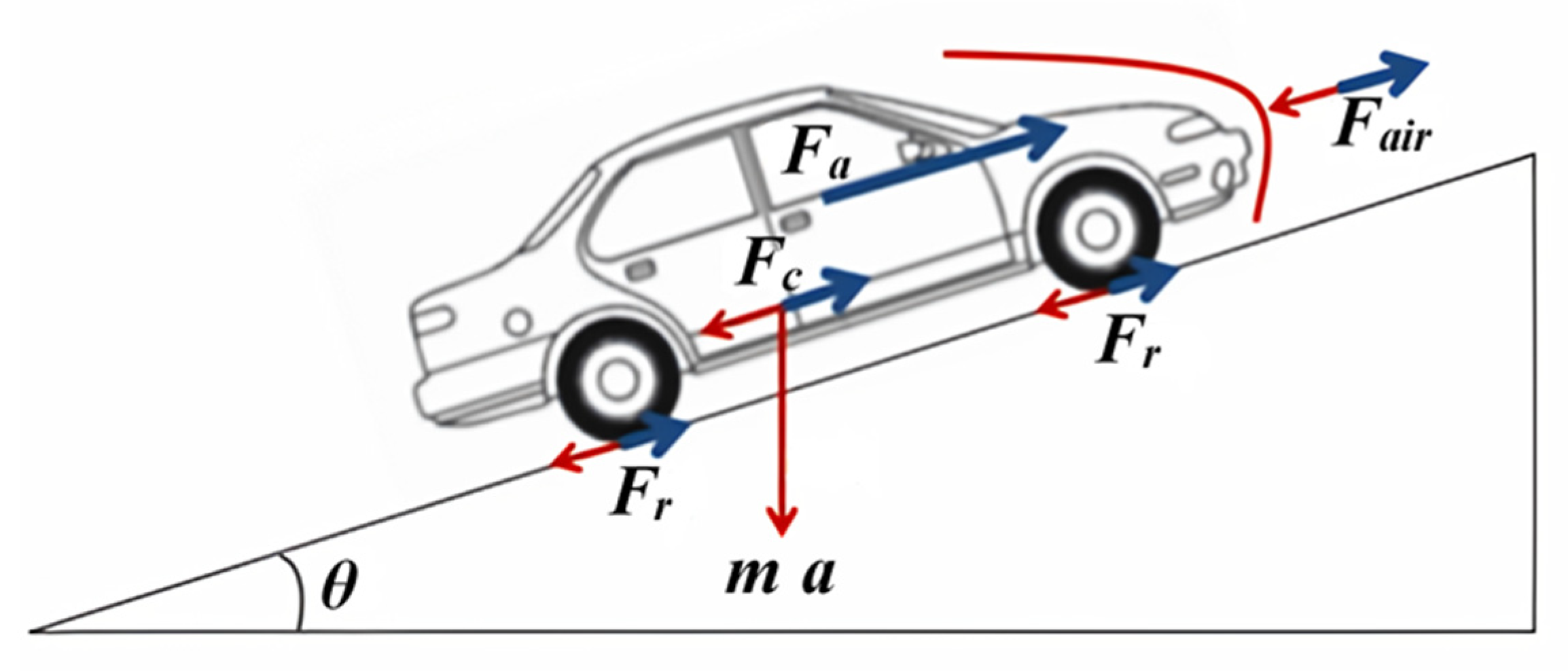
2.2. EV Power Demand Calculation

EV power demand is essential for ANN data training. According to physical laws, power demand can be calculated by analyzing all forces that act in the vehicle and road surfaces. From the force diagram in Figure 2, all forces that act in the vehicle can be evaluated where Fa, Fair, Fc, and Fr denote, respectively, the force for acceleration, the aerodynamic force, a load related to steepness, and rolling resistance. It is possible to calculate the total power requirement by calculating the sum of all force multiplied by the vehicle’s speed, as described in Equation (2).
P t ( t ) = [ m · d v ( t ) d t + m · g · sin θ + m · g · f r · c o s   θ + 1 2 · ρ · A f · C d · ( v ( t ) + v w ) 2 ] · v ( t )
where:
  • Pt = power traction (W);
  • m = vehicle mass (kg);
  • v = speed (m/s);
  • g = gravity force (m/s2);
  • θ = slope angle (rad);
  • fr = rolling resistance coefficient;
  • ρ = air density (kg/m3);
  • Af = vehicle’s frontal area (m2);
  • Cd = aerodynamics resistance coefficient;
  • 𝑣𝑤 = wind speed (m/s).
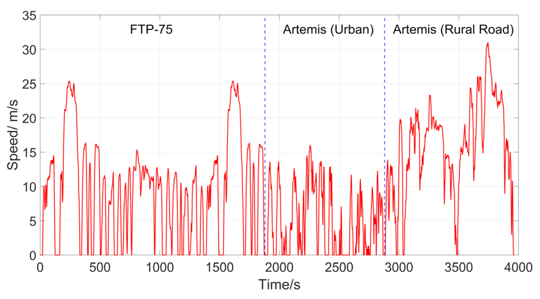
2.3. Driving Cycle

The behavior of an EV is different each time it is used since it depends on traffic conditions. This paper utilizes the driving cycle to develop a power prediction model based on EV behavior. The compound driving cycle (CDC), as shown in Figure 3, is used to train the ANN prediction model. It consists of three driving cycles: the FTP-75 (Federal Test Procedure) driving cycle [21], artemis urban driving cycle, and artemis rural road driving cycle [22]. With a diversified set of driving cycle data, the ANN training is expected to have better results than single set of data [23]. Selecting a driving cycle other than CDC is necessary to prevent any biased performance in the simulation process. Therefore, the WLTP (World Wide Harmonized Light-Duty Vehicle Test Procedure) Class 3 driving cycle is preferred for simulation.

3. Problem Statement and Solving Method

A vehicular network scenario with two electric vehicles traveling in a row based on work in [24] is considered in this paper. Both vehicles support HESS and sensors to measure their states, i.e., speed and acceleration. On top of that, these two vehicles are expected to exchange information with communication devices installed in both vehicles to support vehicle driving. Adding a vehicular network into a power management strategy aims to provide other EVs with information to make the HESS better at distributing power between the battery and SC. However, this advantage comes with a cost where the obtained information cannot be directly utilized to enhance HESS. Therefore, the improved power management strategy using power demand prediction to control HESS is required.
In this section, the problem statement and solving method are presented, respectively. We start by introducing a hierarchical control structure (HCS) as the main approach in this work and elaborate on each method used in each control level of HCS. Then, the complete whole power management strategy is presented.

3.1. Hierarchical Control Structure

This work adopts a two-level hierarchical control structure as a power management control approach, as shown in Figure 4. The first level of control structure is on-board electronic circuit control, where the fuzzy logic controller performs power-split control to the HESS DC/DC converter. The second level of control structure focuses on data prediction to support level one of the control structure. ANN is developed in this work and located at the level two control structure, which is responsible for determining power demand prediction according to the EV’s condition.

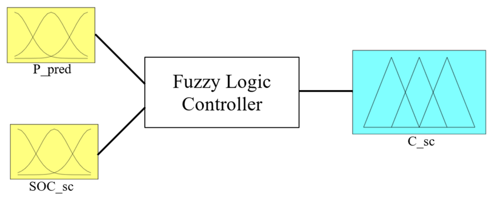
3.2. Level 1: Electronic Circuit Controller

To successfully perform power distribution via the DC/DC converter, a power split controller based on the fuzzy logic controller is applied. The fuzzy logic controller determines the power proportion between the SC and battery under several circumstances based on two inputs (Ppred and SOCSC) and one output (CSC). Ppred is the required power prediction of the load in which will be discussed in the following subsection. SOCSC is the SOC percentage of SC and CSC is the SC discharging coefficient, which is the output of the fuzzy logic controller. The diagram of the fuzzy logic controller is shown in Figure 5.
The control rule of the fuzzy logic controller is given as follows:
  • If the required predicted power is high/medium–high and the SOC of the SC is high/medium, then the SC will supply most of the power.
  • If the required predicted power is high and the SOC of the SC is low, then the SC will still supply most of the power.
  • If the required predicted power is medium–high and the SOC of the SC is low, then the power supplied by the battery and SC is almost balanced.
  • If the required predicted power is medium–low/low and the SOC of the SC is high/medium, then the power supplied by the battery and SC is almost balanced.
  • If the required predicted power is medium–low/low and the SOC of the SC is low, then the battery will supply most of the power.
  • An exception for rule number 4: if the required predicted power is medium-low and the SOC of the SC is high, then the SC will still supply most of the power.
A Mamadani rule-based system is adopted for this fuzzy logic controller. The centroid defuzzification method is selected to obtain a crisp output value. The output value for this fuzzy logic controller is the SC discharging power coefficient (CSC). As the CSC is obtained, the power proportion to be supplied by SC can be determined by
P S C = C S C · P d
where PSC is the power proportion of SC, CSC is SC discharging coefficient, and Pd is power demand. Recall (1) and the new equation can be written as
P b a t t = P d · ( 1 C S C ) .
Since the variables Pd and CSC in (4) are known, the power supplied by the battery (Pbatt) can be determined and controlled.

3.3. Level 2: Reference for on Board Electronic Circuit

The level 2 hierarchical control structure performs power demand prediction of EV and the obtained predictions become a reference input to the fuzzy logic controller at level 1 hierarchical control structure. This paper utilizes an artificial neural network (ANN) as a method to predict the power demand. ANN has been increasingly used and has become a commonly used learning algorithm for detecting relationships in a dataset [25]. In addition, ANN can provide a satisfactory outcome for complex pattern recognition problems due to its processing ability [26]. The principle of ANN or artificial neuron is based on the organic brain. A significant number of neurons are connected, forming a network to process inputs from receptors. Similar to the neuron an organic brain, each of neuron in ANN is connected and each of them is associated with a layer.
The ANN generic architecture used for this work is shown in Figure 6, which is composed of three layers: input, hidden, and output. Each of the neurons is connected with all neurons from subsequent layers, and the connections between them are weighted. The process starts when the neurons in the input layer obtain some inputs value and deliver them to the neurons in the middle layer. The middle layer is called the hidden layer, and the number of hidden layers is known as a value to measure the depth of the ANN. The last layer is the output layer, which presents the final output network to the user. During the process, a functional operation to combine the weighted sum of the input values within the neuron is applied. This operation causes the neural network to perform a nonlinear function operation [27].
In the application for this work, ANN is an excellent method to perform power prediction that requires a nonlinear function. ANN has its hidden layer to map in and map out the relationship between the input and output. Therefore, it can perform linear or nonlinear functions. In [28], multiple linear regression (MLR) is discussed as a statistical analysis method. Fundamentally, MLR is a quick method to generate a function between input and output. It can perform effectively to represent a linear relationship. However, MLR is not possible to represent any nonlinearity. Thus, ANN is a better choice for this work due to its ability to perform nonlinearity functions better than MLR. Furthermore, ANN is simple to use and direct. It is not required to fully understand the algorithm and calculation in its hidden layer, since it is complicated to direct a math function to connect input and output. There are two typical steps to apply ANN [29]. The first step is a training process. During this process, the parameter, input values and target values are determined. Once the ANN has been trained, the testing phase to minimize error is performed.
A vehicular network is a typical form of IoT [30], where information from other EV can be obtained and used as input data for power prediction calculation. For this work, the power prediction is calculated based on EV’s status conditions: speed and acceleration. The study in [31] stated that the vehicle speed and acceleration are dynamic and difficult to predict. Which leads to the relation between the EV state and future power demand as a complex nonlinear function. Therefore, this work adopts ANN, which has the ability to process nonlinear functions to find the relation between the EV condition and future power demand. A brief ANN prediction model for this work is shown in Figure 7. The prediction process begins with three inputs based on other EV information data in which two of them correspond to the previous speed at T-1 and T-2 while the other one is the vehicle acceleration data. All of the obtained inputs data will be calculated by ANN to perform power prediction. Thus, the output would be the predicted future power demand at time T and more details about the ANN configuration set up will be covered in Section 4.
Considering a practical application and safety issues where the average time response of an unalerted driver is around 2.5 s [32,33], thus the recommended time step for ANN prediction model is one-fifth of driver time response. It is necessary to mention that this paper considers information exchange by using only a vehicular network and without any other identification system. With the help from the vehicular network, the prediction model could essentially know whether the other EVs is accelerating or slowing down with this strategy. This might provide the future power prediction for the EV itself and improve a better power split in HESS. This prediction model performance is discussed in Section 4.

3.4. Hierarchical Power Management for Connected EV

A complete Hierarchical Power Management for Connected EV strategy starts from level 2 hierarchical control to predict the power demand and the processes continue until HESS regulates the battery and SC discharging. The overall strategy procedure of the proposed hierarchical power management for connected EVs is shown in Figure 8 as a flow chart.

4. Simulation Result and Analysis

Simulations of the proposed hierarchical power management for a connected EV are presented in this section. This section has three parts: simulation parameters and setup, power demand prediction results, and HESS power distribution results. The simulation is performed in MATLAB/Simulink R2020a for 300 s of simulation time duration. This simulation aims to test the accuracy of power demand prediction and test the proposed power management strategy’s ability to distribute power between the battery and SC.

4.1. Simulation Parameters and Setup

Traffic data are essential in obtaining power demand prediction from the proposed power management strategy. However, V2V technologies are not widely used yet, which means that obtaining data from other EVs is difficult in experiments [24]. Therefore, the data for this simulation are pre-processed data from the driving cycle profile. The WLTP class 3 driving cycle profile [34] is adopted for this simulation, as shown in Figure 9.
The simulation for calculated power demand is based on EV model BWM i3s (120 Ah). The parameter for power demand calculation as in Equation (2) is shown in Table 1 while the parameters for HESS are shown in Table 2. The vehicle mass (𝑚) and road slope (θ) significantly impact power demand calculation. In contrast, other parameters such as air density, EV frontal area and wind speed do not significantly impact.

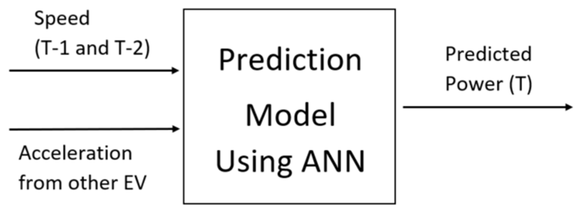
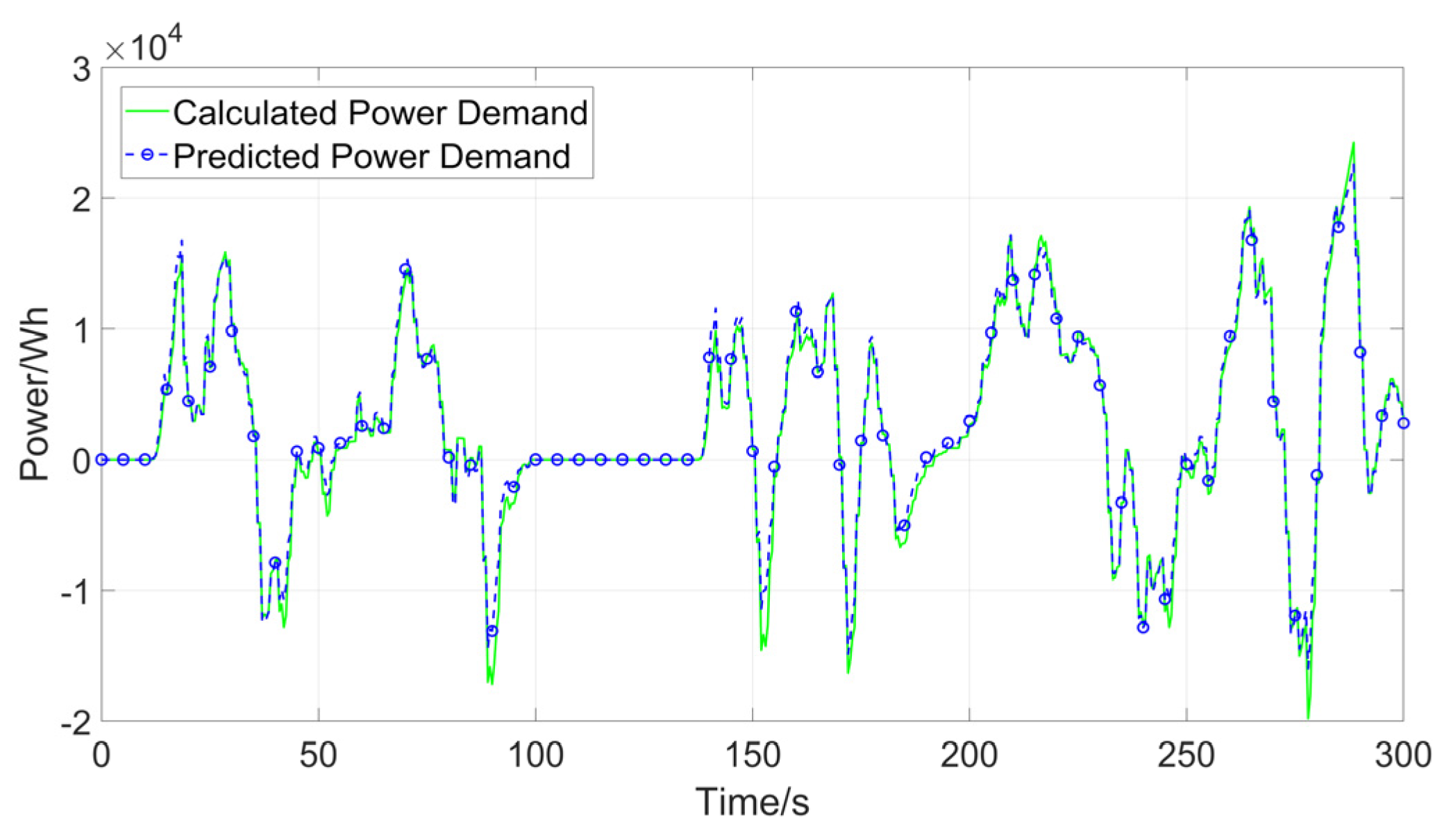
4.2. Power Demand Prediction Results and Analysis

The development of mapping ability, training, and testing data processes has been implemented using the ANN MATLAB software toolbox. The number of neurons in the fitting network’s hidden layer is set to be ten as default. Input data of 7922 samples from selected driving cycles (FTP, ART Urban, and Art Road) have been divided into 70% of ANN training, 15% of ANN testing, and 15% for validation data. In order to achieve maximum result, the prediction model is trained to achieve above 0.9 of R regression value by using the Levenberg–Marquardt machine learning algorithm, which indicates the good predicting performance of the proposed method. The power demand prediction result is shown in Figure 10.

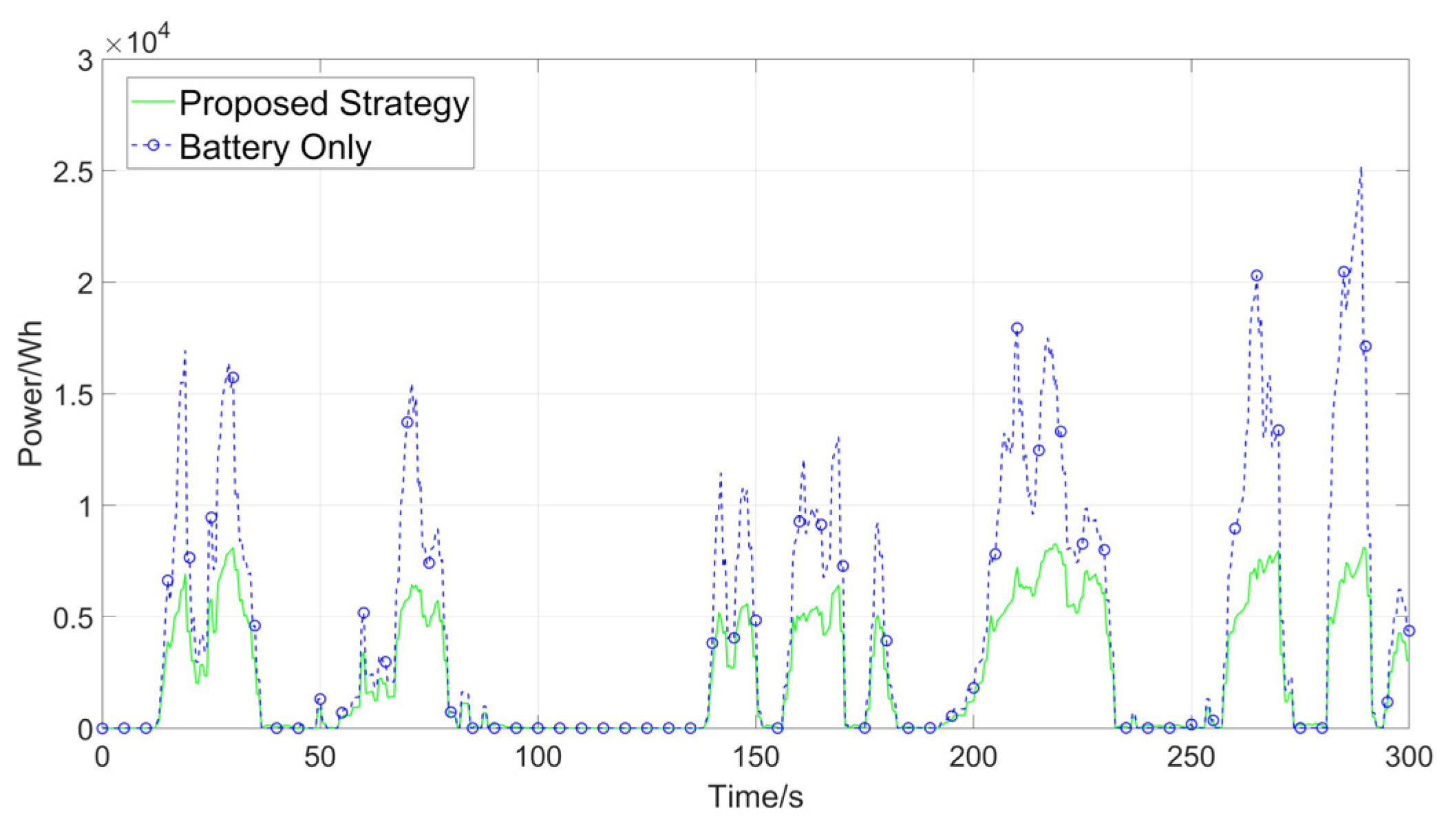
4.3. Power Distribution Results and Analysis

The simulation results of the proposed power management strategy in performing HESS power distribution is shown in Figure 11. The figure shows simulation result where power demand is supported by the SC and battery simultaneously. For instance, from around t = 250 s to t = 300 s, there are two high power demand spikes, and the SC supports the battery to provide a fast burst power demand. This result indicates that the proposed power management strategy successfully satisfied the objective of HESS.
The SOC of the battery is shown in Figure 12 which demonstrates that the battery performs without any charging state and the initial SOC is 80%. Meanwhile, during the simulation, the SC supports the battery and absorbs energy while the EV slows down. For example, from around t = 230 s to t = 250 s, the EV slows down, and the system recycles regenerative energy to charge the SC. The changes in the SOC of the SC for 300 s simulation is also shown in Figure 13. Compared to the SOC level of the battery, the SOC of the SC is more volatile which indicates the SC performs fast and varied energy transfer than the battery during the simulation.
The comparison study to evaluate the performance of the proposed power management strategy is also carried out in this section. Two performance indicators that are corresponding to the discharging battery behavior will be used to assess the result. The first indicator is the average of the discharging battery power as described in Equation (5).
P ¯ b a t t = 1 N · t = 1 N P b a t t ( t )
where P ¯ b a t t is the average discharging power and N is the number of total data. This paper uses standard deviation as the second indicator, described in Equation (6), to calculate power variation which is normal and widely used to represent variance in many cases and applications.
σ = 1 N · t = 1 N ( P b a t t ( t ) P ¯ b a t t ) 2
The proposed power management strategy will be compared to battery-only strategy by using the same WLTP class 3 driving cycle for 300 s. The battery-only strategy works only with battery pack as the main energy source. Thus, the battery-only strategy has no power split process and future power demand prediction. Figure 14 demonstrates the battery discharging power comparison between the proposed power management and battery-only strategy and the results analysis of the performance are summarized in Table 3. From the result, by taking the future power demand and power split into account, the proposed power management strategy has lower average battery power and power variation compared to battery-only. The average battery power is reduced by 46.1% and the battery power variation is reduced by 52.3%.

5. Conclusions

A power management strategy for connected electric vehicles has been presented in this paper to reduce discharging battery power and fluctuation. The proposed strategy is based on hierarchical control structure, which is composed by two control levels, to perform future data prediction and power distribution. The ANN is utilized in level two of control structure to perform power demand prediction with the assumption that a vehicular network scenario is deployed. Then, the predicted power demand is used as a reference input to the fuzzy logic controller in the level one control structure. Fuzzy logic controller aims to control HESS power split by generating SC discharging coefficient that represents the power ratio between battery and SC. The simulation result shows that the average discharging battery magnitude and battery power fluctuation are well reduced by 46.1% and 52.3% by using the proposed strategy compared to the battery-only case. The proposed strategy that performs future power prediction could successfully reduce battery fluctuation. Our future work aims to enhance the power demand prediction result by using real-time driving information and adding other IoT structures such as traffic lights and vehicle distance into the scenario of the vehicular network.

Author Contributions

Methodology, C.Y.A.; software, C.Y.A.; writing—original draft preparation, C.Y.A.; supervision, Y.W. and W.J.; project administration, Y.W. and W.J.; funding acquisition, Y.W. and W.J. All authors have read and agreed to the published version of the manuscript.

Funding

This research was funded in part by the start-up funds of Nanjing University of Finance and Economics, grant number W-YXW20001 and in part by the Power Electronics Science and Education Development Program of Delta Group, grant number DREK2020005.

Institutional Review Board Statement

Not applicable.

Informed Consent Statement

Not applicable.

Acknowledgments

The authors thank the two anonymous reviewers for their constructive comments which profoundly improved the paper.

Conflicts of Interest

The authors declare no conflict of interest.

References

  1. Ranawat, D.; Prasad, M. A review on electric vehicles with perspective of battery management system. In Proceedings of the 2018 International Conference on Electrical, Electronics, Communication, Computer, and Optimization Techniques (ICEECCOT), Msyuru, India, 14–15 December 2018; pp. 1539–1544. [Google Scholar]
  2. Andwari, A.M.; Pesiridis, A.; Rajoo, S.; Martinez-Botas, R.; Esfahanian, V. A review of Battery Electric Vehicle technology and readiness levels. Renew. Sustain. Energy Rev. 2017, 78, 414–430. [Google Scholar] [CrossRef]
  3. Weiss, H.; Winkler, T.; Ziegerhofer, H. Large lithium-ion battery-powered electric vehicles—From idea to reality. In Proceedings of the 2018 ELEKTRO, Mikulov, Czech Republic, 21–23 May 2018; pp. 1–5. [Google Scholar]
  4. Ajith, T.A.; Dhas, G.J.S. A SurveyOn Hybrid Energy Storage System for EV With Regenerative Braking. In Proceedings of the 2018 International Conference on Control, Power, Communication and Computing Technologies (ICCPCCT), Msyuru, India,, 14–15 December 2018; pp. 250–255. [Google Scholar]
  5. Kouchachvili, L.; Yaïci, W.; Entchev, E. Hybrid battery/supercapacitor energy storage system for the electric vehicles. J. Power Sources 2018, 374, 237–248. [Google Scholar] [CrossRef]
  6. Song, Z.; Hou, J.; Xu, S.; Ouyang, M.; Li, J. The influence of driving cycle characteristics on the integrated optimization of hybrid energy storage system for electric city buses. Energy 2017, 135, 91–100. [Google Scholar] [CrossRef]
  7. Bhat, P.N.; Veena, M. Design of Efficient Power Management System using Ultra Capacitors. In Proceedings of the 2019 Global Conference for Advancement in Technology (GCAT), Bangalore, India, 18–20 October 2019; pp. 1–5. [Google Scholar]
  8. Song, Z.; Hou, J.; Hofmann, H.; Li, J.; Ouyang, M. Sliding-mode and Lyapunov function-based control for battery/supercapacitor hybrid energy storage system used in electric vehicles. Energy 2017, 122, 601–612. [Google Scholar] [CrossRef]
  9. Wang, X.; Tao, J.; Zhang, R. Fuzzy energy management control for battery/ultra-capacitor hybrid electric vehicles. In Proceedings of the 2016 Chinese Control and Decision Conference (CCDC), Yinchuan, China, 28–30 May 2016; pp. 6207–6211. [Google Scholar]
  10. Muntaser, A.; Elwarfalli, H.; Kumar, J.; Subramanyam, G. Development of advanced energy storage system using fuzzy control. In Proceedings of the 2016 IEEE National Aerospace and Electronics Conference (NAECON) and Ohio Innovation Summit (OIS), Dayton, OH, USA, 25–29 July 2016; pp. 179–182. [Google Scholar]
  11. Martinez, D.; Poveda, J.; Montenegro, D. Li-ion battery management system based in fuzzy logic for improving electric vehicle autonomy. In Proceedings of the 2017 IEEE Workshop on Power Electronics and Power Quality Applications (PEPQA), Bogotá, Colombia, 31 May 2017–2 June 2017; pp. 1–6. [Google Scholar]
  12. Seixas, L.D.; Tosso, H.G.; Corrêa, F.C.; Eckert, J.J. Particle Swarm Optimization of a Fuzzy Controlled Hybrid Energy Storage System-HESS. In Proceedings of the 2020 IEEE Vehicle Power and Propulsion Conference (VPPC), Gijon, Spain, 18 November–16 December 2020; pp. 1–6. [Google Scholar]
  13. Wang, L.; Wang, Y.; Liu, C.; Yang, D.; Chen, Z. A power distribution strategy for hybrid energy storage system using adaptive model predictive control. IEEE Trans. Power Electron. 2019, 35, 5897–5906. [Google Scholar] [CrossRef]
  14. Chen, H.; Xiong, R.; Lin, C.; Shen, W. Model predictive control based real-time energy management for a hybrid energy storage system. CSEE J. Power Energy Syst. 2020, 7, 862–874. [Google Scholar]
  15. Mei, Y.; Li, X.; Qi, Y. A model predictive control method for three-level bi-directional DC-DC converter in renewable generation system. In Proceedings of the 2015 18th International Conference on Electrical Machines and Systems (ICEMS), Pattaya, Thailand, 25–28 October 2015; pp. 417–421. [Google Scholar]
  16. Gomozov, O.; Trovão, J.P.F.; Kestelyn, X.; Dubois, M.R. Adaptive energy management system based on a real-time model predictive control with nonuniform sampling time for multiple energy storage electric vehicle. IEEE Trans. Veh. Technol. 2016, 66, 5520–5530. [Google Scholar] [CrossRef]
  17. Moser, D.; Schmied, R.; Waschl, H.; del Re, L. Flexible spacing adaptive cruise control using stochastic model predictive control. IEEE Trans. Control Syst. Technol. 2017, 26, 114–127. [Google Scholar] [CrossRef]
  18. Song, Z.; Li, J.; Hou, J.; Hofmann, H.; Ouyang, M.; Du, J. The battery-supercapacitor hybrid energy storage system in electric vehicle applications: A case study. Energy 2018, 154, 433–441. [Google Scholar] [CrossRef]
  19. Xiong, R.; Chen, H.; Wang, C.; Sun, F. Towards a smarter hybrid energy storage system based on battery and ultracapacitor-A critical review on topology and energy management. J. Clean. Prod. 2018, 202, 1228–1240. [Google Scholar] [CrossRef]
  20. Zhang, Q.; Li, G. Experimental study on a semi-active battery-supercapacitor hybrid energy storage system for electric vehicle application. IEEE Trans. Power Electron. 2019, 35, 1014–1021. [Google Scholar] [CrossRef]
  21. Hwang, H.-Y. Developing Equivalent Consumption Minimization Strategy for Advanced Hybrid System-II Electric Vehicles. Energies 2020, 13, 2033. [Google Scholar] [CrossRef]
  22. André, M. The ARTEMIS European driving cycles for measuring car pollutant emissions. Sci. Total Environ. 2004, 334, 73–84. [Google Scholar] [CrossRef] [PubMed]
  23. Lago, L.F.; Faceroli, S.T.; Ferreira, R.A.; Rodrigues, M.C. Power Demand Prediction Based on Mixed Driving Cycle Applied to Electric Vehicle Hybrid Energy Storage System. In Proceedings of the 2019 IEEE 15th Brazilian Power Electronics Conference and 5th IEEE Southern Power Electronics Conference (COBEP/SPEC), São Paulo, Brazil, 1–4 December 2019; pp. 1–6. [Google Scholar]
  24. Hu, Y.; Chen, C.; He, J.; Yang, B.; Guan, X. IoT-based proactive energy supply control for connected electric vehicles. IEEE Internet Things J. 2019, 6, 7395–7405. [Google Scholar] [CrossRef]
  25. Burghardt, F.; Garbe, R. Introduction of artificial neural networks in EMC. In Proceedings of the 2018 IEEE Symposium on Electromagnetic Compatibility, Signal Integrity and Power Integrity (EMC, SI & PI), Long Beach, CA, USA, 30 July 2018–3 August 2018; pp. 165–169. [Google Scholar]
  26. Syafie, L.; Indra, D.; Hamrul, H.; Anraeni, S.; Ilmawan, L.B. Comparison of Artificial Neural Network and Gaussian Naïve Bayes in Recognition of Hand-Writing Number. In Proceedings of the 2018 2nd East Indonesia Conference on Computer and Information Technology (EIConCIT), South Sulawesi, Indonesia, 6–7 November 2018; pp. 276–279. [Google Scholar]
  27. Sze, V.; Chen, Y.-H.; Yang, T.-J.; Emer, J.S. Efficient processing of deep neural networks: A tutorial and survey. Proc. IEEE 2017, 105, 2295–2329. [Google Scholar] [CrossRef] [Green Version]
  28. Wang, Y.; Shen, Y.; Mao, S.; Cao, G.; Nelms, R.M. Adaptive learning hybrid model for solar intensity forecasting. IEEE Trans. Ind. Inform. 2018, 14, 1635–1645. [Google Scholar] [CrossRef]
  29. Das, T.; Tripathy, A.K.; Mishra, A.K. Optical character recognition using artificial neural network. In Proceedings of the 2017 international conference on computer communication and informatics (ICCCI), Coimbatore, India, 5–7 January 2017; pp. 1–4. [Google Scholar]
  30. Wang, Y.; Shen, Y.; Mao, S.; Chen, X.; Zou, H. LASSO and LSTM integrated temporal model for short-term solar intensity forecasting. IEEE Internet Things J. 2018, 6, 2933–2944. [Google Scholar] [CrossRef]
  31. Kim, E.; Lee, J.; Shin, K.G. Real-time prediction of battery power requirements for electric vehicles. In Proceedings of the 2013 ACM/IEEE International Conference on Cyber-Physical Systems (ICCPS), Philadelphia, PA, USA, 8–11 April 2013; pp. 11–20. [Google Scholar]
  32. Summala, H. Brake reaction times and driver behavior analysis. Transp. Hum. Factors 2000, 2, 217–226. [Google Scholar] [CrossRef]
  33. Taoka, G.T. Brake reaction times of unalerted drivers. ITE J. 1989, 59, 19–21. [Google Scholar]
  34. Bielaczyc, P.; Woodburn, J.; Szczotka, A. The WLTP as a new tool for the evaluation of CO2 emissions. In Proceedings of the FISITA World Automotive Congress 2014, Maastricht, The Netherlands, 2–6 June 2014. [Google Scholar]
Figure 1. Hybrid energy storage system model.
Applsci 12 00052 g001
Figure 2. Force diagram on EV.
Applsci 12 00052 g002
Figure 3. Compound driving cycle.
Applsci 12 00052 g003
Figure 4. Hierarchical control structure.
Applsci 12 00052 g004
Figure 5. Fuzzy logic controller model.
Applsci 12 00052 g005
Figure 6. ANN architecture.
Applsci 12 00052 g006
Figure 7. ANN prediction model.
Applsci 12 00052 g007
Figure 8. Hierarchical power management for connected EV.
Applsci 12 00052 g008
Figure 9. WLTP class 3 driving cycle profile.
Applsci 12 00052 g009
Figure 10. Power demand prediction result.
Applsci 12 00052 g010
Figure 11. HESS power distribution result.
Applsci 12 00052 g011
Figure 12. SOC level of battery.
Applsci 12 00052 g012
Figure 13. SOC level of SC.
Applsci 12 00052 g013
Figure 14. Discharging battery power comparison.
Applsci 12 00052 g014
Table 1. Parameter for power demand calculation.
ParametersValue
m 1730 kg
g 9.81 m/s2
θ0 rad
f r 0.015
ρ 1.25 km/m3
A f 2.39 m2
C d 0.3
𝑣𝑤0 m/s
Table 2. Parameter for HESS.
ParametersBattery PackSC Pack
Voltage352 V297 V (2.7 V Cell)
Rated Capacity120 Ah310 F (5.6 F in total, 110 series, 2 parallel)
Energy42.2 kWh68.6 Wh
Initial SOC80%75%
TypeLithium-IonGeneric model
Table 3. Performances Comparison.
StrategyAverage Battery Power (kWh)Battery Power Variation (kWh)
Battery-only4.265.61
Proposed Strategy2.292.67
Publisher’s Note: MDPI stays neutral with regard to jurisdictional claims in published maps and institutional affiliations.

