
Development of a Pre-Evaluation and Health Monitoring System for FAST Cable-Net Structure


Abstract
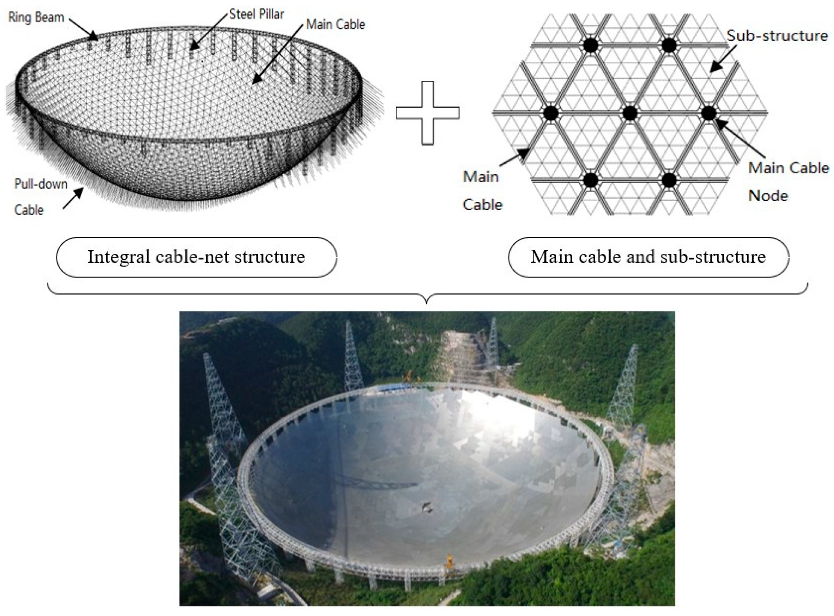
:1. Introduction
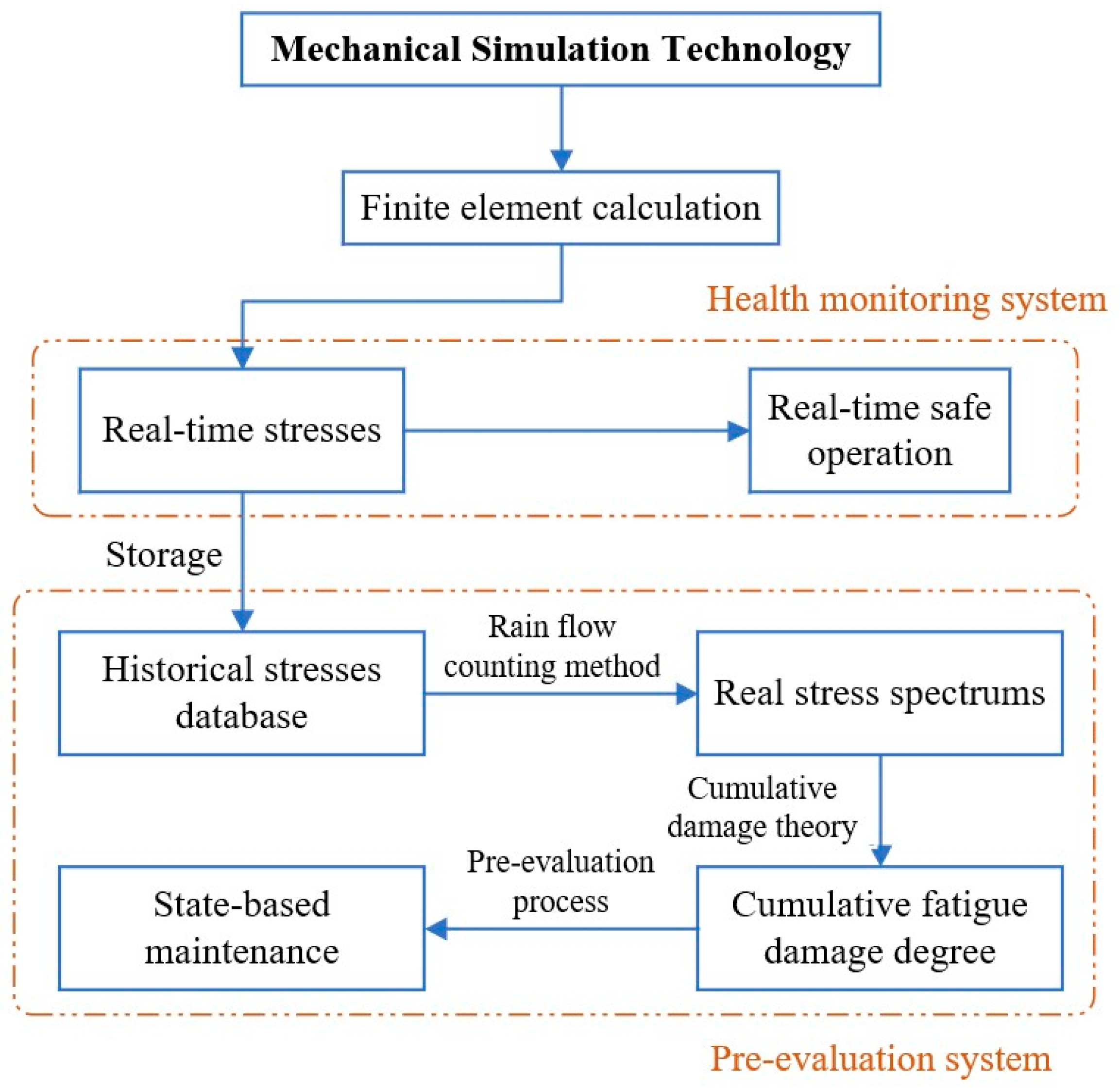
2. Basic Concept of Mechanical Simulation Technology
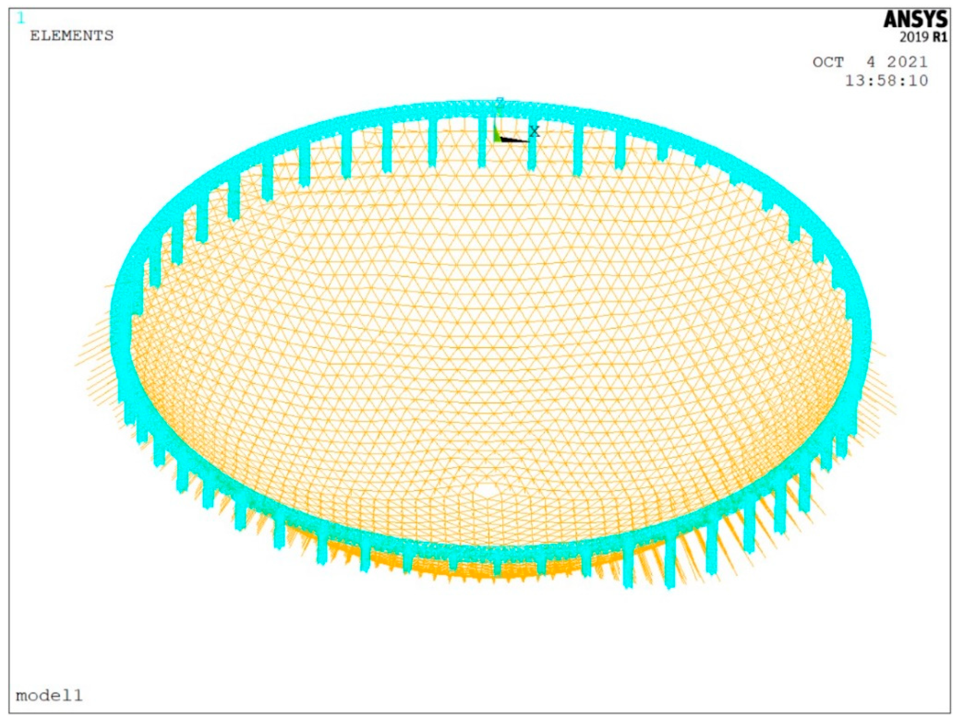
3. Establishment of the FAST MST Model
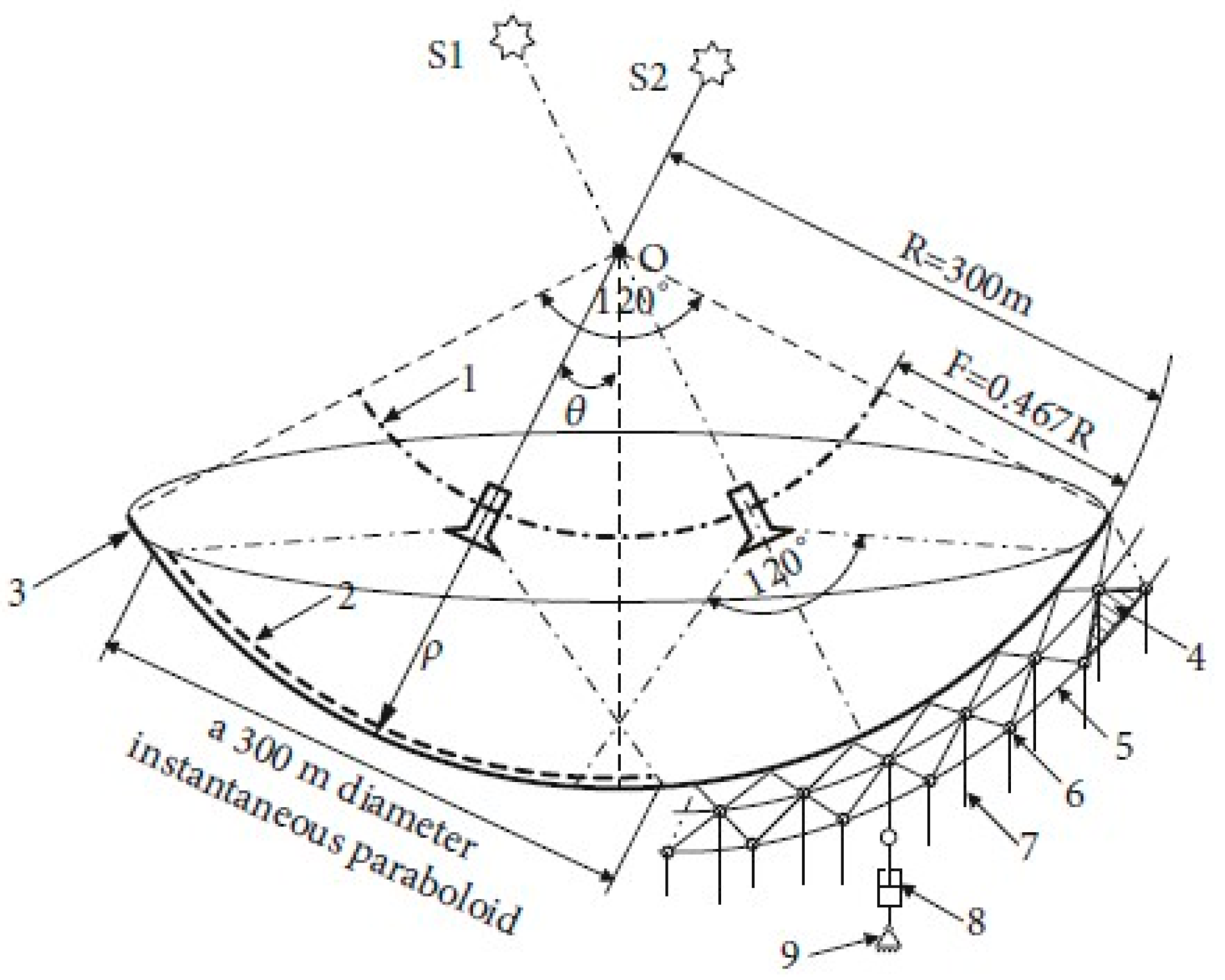
3.1. Method of Obtaining Data of the FAST Cable Net
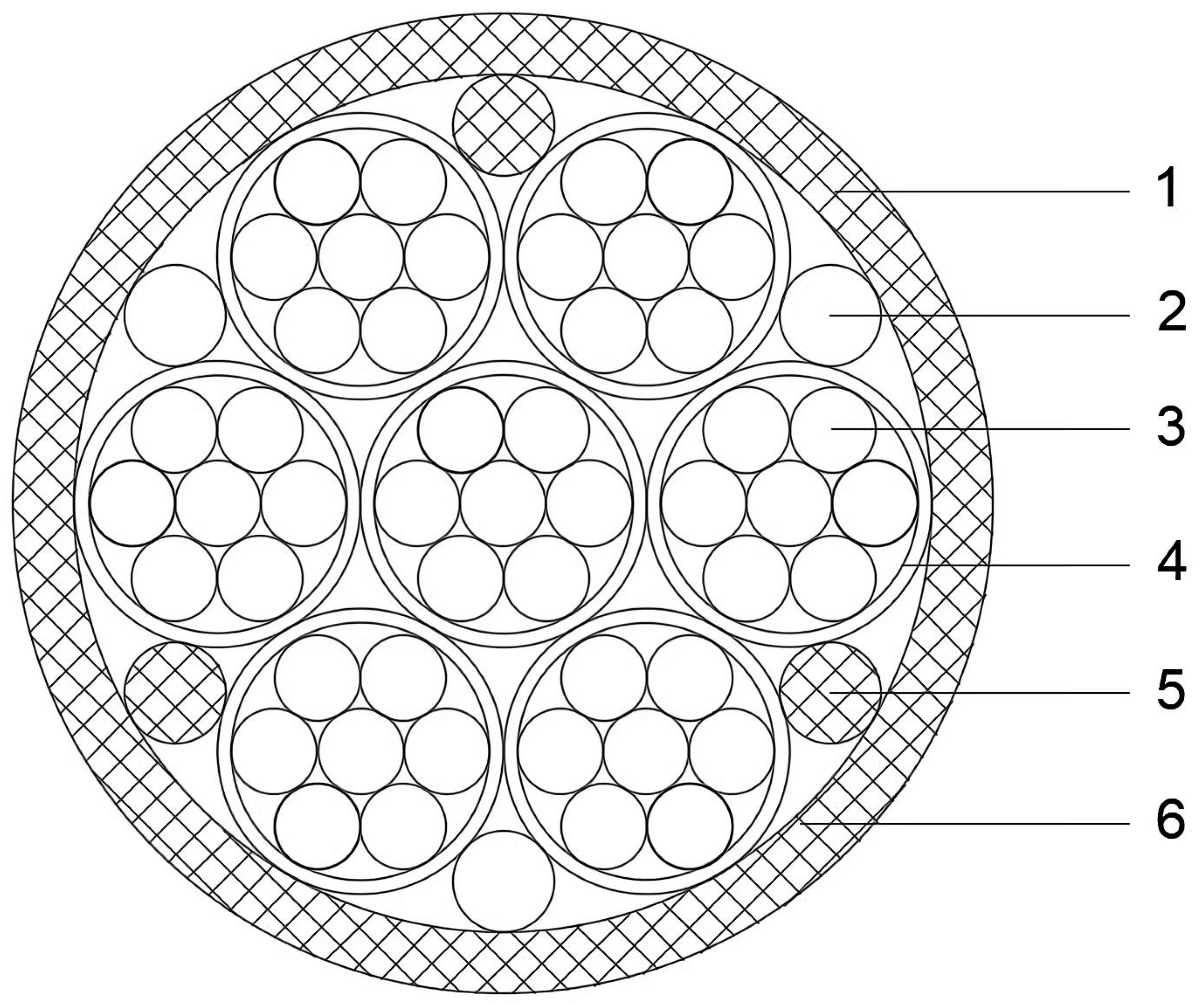
3.2. Types and Parameters of FAST Cables and Connecting Nodes
- (1)
- (2)
- The elastic modulus of the cable: E = (190 ± 10) GPa;
- (3)
- The linear temperature expansion coefficient: α = 1.2 × 10⁻⁵;
- (4)
- Other parameters of the cables are shown in Table 1.
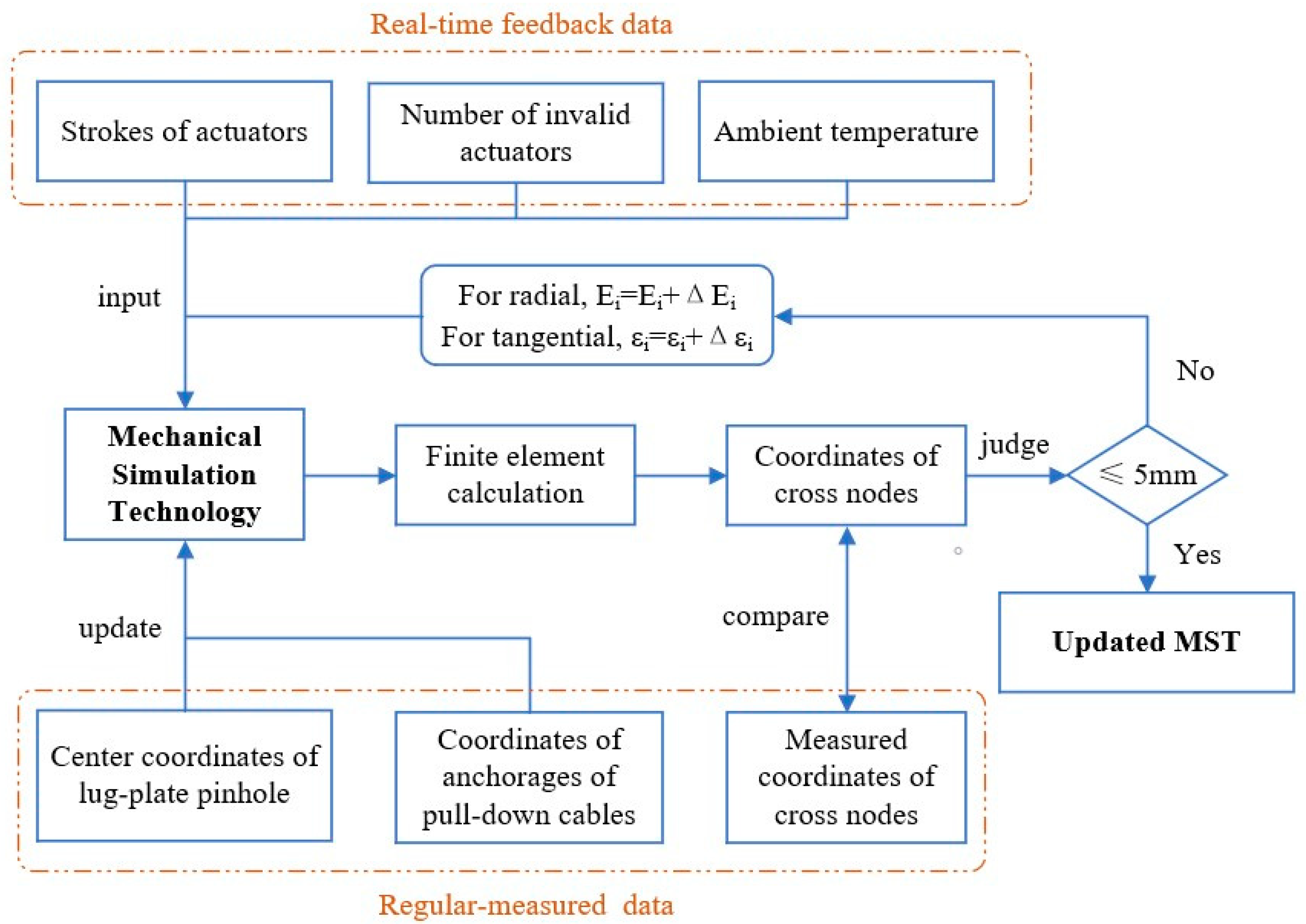
3.3. Update Process of MST Model
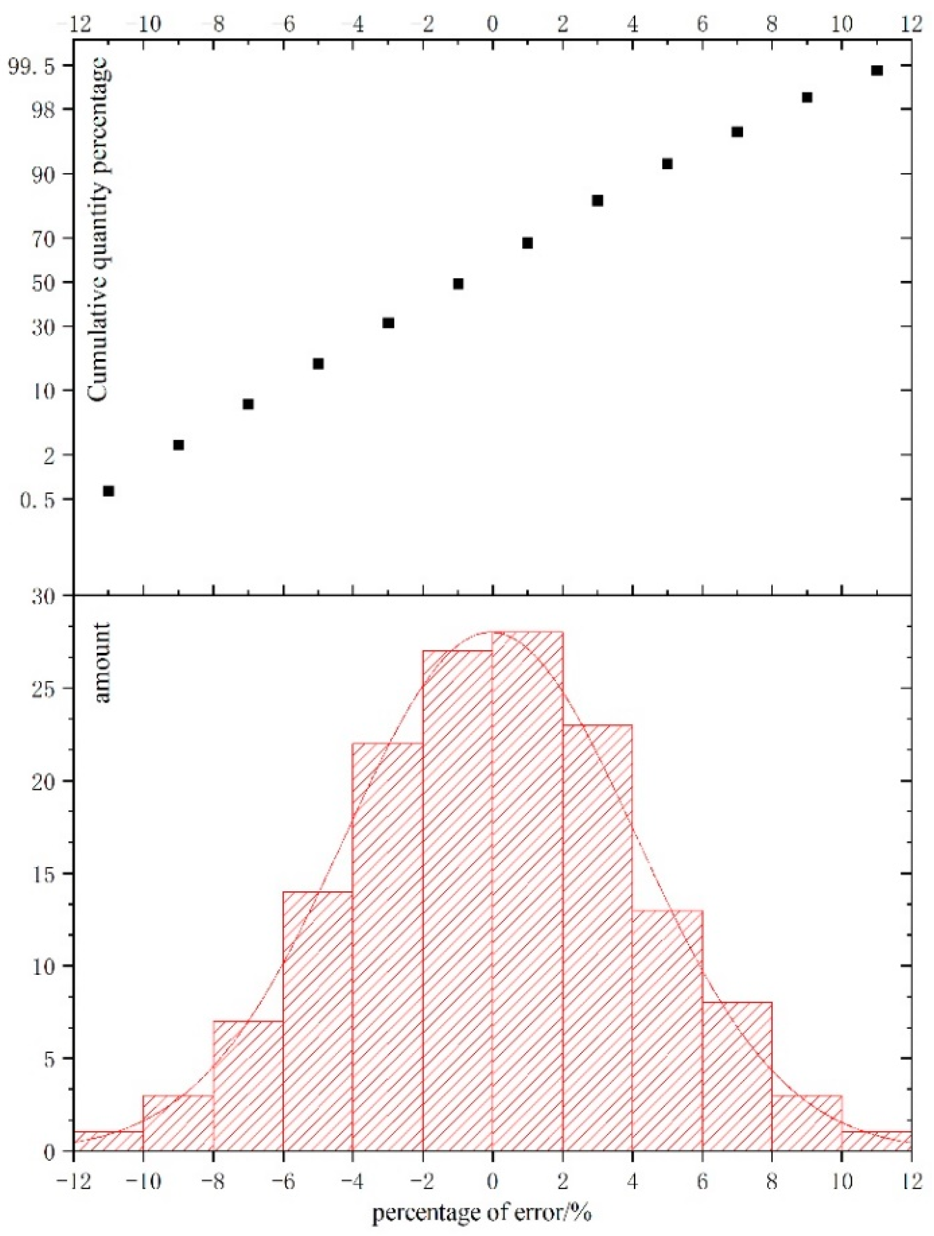
3.4. Verification of the Accuracy of the MST Model
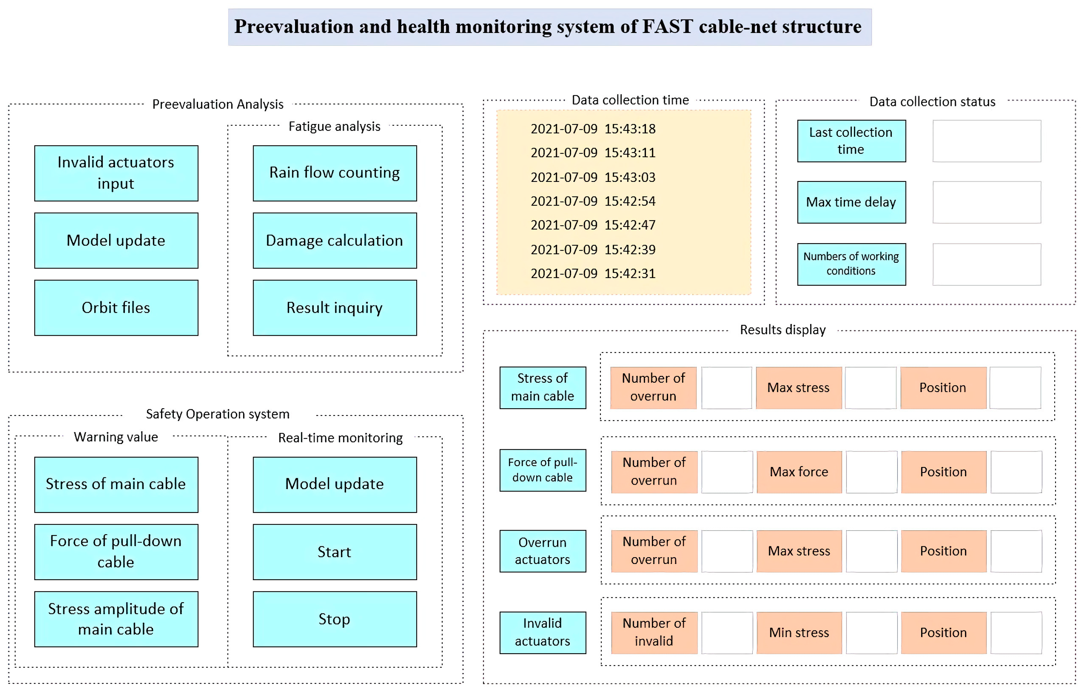
4. Pre-Evaluation and Health Monitoring System of FAST
4.1. Pre-Evaluation System
4.2. Health Monitoring System
5. Conclusions
- MST is applicable to the establishment of the FAST model, which can be updated automatically and over time. The model fits in well with the on-site structure.
- A method to update the FAST model with regularly measured data is proposed, and the field test proves that the updated model is highly reliable.
- A PHM system consisting of both pre-evaluation and health monitoring components has been developed to provide a visual and automated early-warning system for the structural health monitoring of FAST, which significantly facilitates the maintenance work of on-site staff. The PHM system has provided vital support for the stable observations of FAST.
Author Contributions
Funding
Data Availability Statement
Acknowledgments
Conflicts of Interest
References
- Nan, R. Five-hundred-meter aperture spherical radio telescope (FAST). Sci. China Ser. G 2006, 49, 129–148. [Google Scholar] [CrossRef]
- Nan, R.; Li, D.I.; Jin, C.; Wang, Q.; Zhu, L.; Zhu, W.; Zhang, H.; Yue, Y.; Qian, L. The Five-hundred-meter Aperture Spherical Radio Telescope (FAST) Project. Int. J. Mod. Phys. D 2012, 20, 989–1024. [Google Scholar] [CrossRef] [Green Version]
- Jin, X.; Fan, F.; Qian, H.; Shen, S. Optimal sensor placement of 30-meter scaled structure of large telescope FAST. J. Harbin Inst. Technol. 2009, 41, 31–35. [Google Scholar]
- Yao, R.; Zhu, W.; Yang, Q. Dimension optimization design of the Stewart platform in FAST. Adv. Des. Technol. 2011, 308–310, 2110–2113. [Google Scholar] [CrossRef]
- Ming, Z.; Wang, Q.; Zheng, L.; Wu, M.; Xue, J. Research for reliability of the actuator of fast reflector based on FMECA. In Proceedings of the 2014 International Conference on Reliability, Maintainability and Safety (ICRMS 2014), Guangzhou, China, 6–8 August 2014. [Google Scholar]
- Lu, Y.; Ren, G. Simulation of the Cable Mesh Reflector for the Large Radio Telescope Fast. Eng. Mech. 2007, 24, 165–169. [Google Scholar]
- Kong, X.; Jiang, P.; Wang, Q. A Study of Influences of Value Variations of Structural Parameters on Forces in Cables in the Net Structure of Cables of the FAST. Astron. Res. Technol. 2015, 12, 159–165. [Google Scholar]
- Li, Q.; Jiang, P.; Li, H. Prognostics and health management of FAST cable-net structure based on digital twin technology. Res. Astron. Astrophys. 2020, 20, 067. [Google Scholar] [CrossRef]
- Jiang, P.; Wang, Q.M.; Zhao, Q. Optimization and Analysis on Cable Net Structure Supporting the Reflector of the Large Radio Telescope FAST. Appl. Mech. Mater. 2011, 94–96, 979–982. [Google Scholar] [CrossRef]
- Fan, F.; Jin, X.; Qian, H. Fatigue analysis of FAST cable-net structure under long-term active shape-changing work. J. Build. Struct. 2010, 31, 17–23. [Google Scholar]
- Luo, B.; Guo, Z.; Wang, K.; Xiao, Q. Performance optimization analysis of FAST reflector supported cable-net based on initial baseline state. China Civ. Eng. J. 2015, 48, 12–22. [Google Scholar]
- Sun, X.; Wang, Q.; Zhu, M.; Wu, M. Application of optical fibre Bragg grating strain gauge to cable force monitoring of FAST. Opt. Precis. Eng. 2015, 23, 919–925. [Google Scholar]
- Zhu, M.; Yang, L.; Lei, Z.; Wang, Y. Fuzzy Fault Tree Theory-Based Fault Search Strategy Research for FAST Hydraulic Actuators. In Proceedings of the 2016 International Conference on Reliability, Maintainability and Safety (ICRMS 2016), Hangzhou, China, 26–28 October 2016. [Google Scholar]
- Zhu, W.; Qin, H.; Li, J.; Ou, J. Monitoring Cable Force of FAST Project Based on Fibre Bragg Grating Sensor External Installed on Anchorage Zone. J. Mech. Eng. 2017, 53, 23–30. [Google Scholar] [CrossRef]
- Fan, F.; Wang, H.; Qian, H.; Jin, X.; Chen, M.; Shen, S. Investigation and application of early-warning system for safety of support structure for active reflector of FAST. J. Build. Struct. 2010, 31, 24–31. [Google Scholar]
- Shi, Y.; Yao, B.; Zhang, Q.; Mei, X. Study on Numerical Simulation Technology Based on ANSYS of Fracture Behavior in Metal Forming Process. Appl. Mech. Mater. 2011, 130–134, 976. [Google Scholar] [CrossRef]
- Sun, X.; Wang, Q.; Wu, M. Performance Tests of a Monitoring-Management System of Actuators for the FAST. Astron. Res. Technol. 2013, 10, 227–233. [Google Scholar]
- Liu, Z.; Jiang, A.; Zhang, A.; Xing, Z.; Du, X. Intelligent Prediction Method for Operation and Maintenance Safety of Prestressed Steel Structure Based on Digital Twin Technology. Adv. Civ. Eng. 2021, 2021, 6640198. [Google Scholar] [CrossRef]
- Xu, M.; Yang, C.; Duan, Y.; Wang, Y.; Huang, W.; Ma, F. Fatigue Life Prediction Based on Rain-flow Counting Method. Mach. Des. Res. 2016, 32, 184–187. [Google Scholar]
- Wang, H.; Wang, K.; Zhao, L. Random Vibration Fatigue Life Analysis Based on Nonlinear Cumulative Damage. J. Vib. Meas. Diagn. 2018, 38, 991–996. [Google Scholar]
- Zhang, H.; Wu, M.; Yue, Y.; Gan, H.; Hu, H.; Huang, S. EMC design for actuators in the FAST reflector. Res. Astron. Astrophys. 2018, 18, 048. [Google Scholar] [CrossRef] [Green Version]


| Serial Number | Specification | Cable Body | Double Cable Heads | Connection Node | |||||
|---|---|---|---|---|---|---|---|---|---|
| Cross-Sectional Area | Linear Weight | Outer Diameter | Limit Cable Force | Weight | Length | Weight | Outsourcing Diameter of Pinhole Centre | ||
| cm2 | kg/m | mm | kN | kg | mm | kg | mm | ||
| 1 | OVM.ST15-1 | 1.4 | 1.37 | 23 | 260 | 10.5 | 390 | — | — |
| 2 | OVM.ST15-2 | 2.8 | 3.29 | 44 | 520 | 40 | 640 | 41 | 270 |
| 3 | OVM.ST15-2J3 | 3.4 | 3.65 | 44 | 629.5 | 40 | 640 | 41 | 270 |
| 4 | OVM.ST15-3 | 4.2 | 4.52 | 47 | 782 | 52 | 700 | 55 | 290 |
| 5 | OVM.ST15-3J3 | 4.8 | 4.87 | 47 | 891.5 | 52 | 700 | 55 | 290 |
| 6 | OVM.ST15-4 | 5.6 | 5.71 | 51 | 1040 | 70 | 800 | 90 | 360 |
| 7 | OVM.ST15-4J3 | 6.2 | 6.07 | 51 | 1149.5 | 70 | 800 | 90 | 360 |
| 8 | OVM.ST15-5 | 7 | 7.29 | 62 | 1300 | 87 | 830 | 115 | 390 |
| 9 | OVM.ST15-5J3 | 7.6 | 7.75 | 62 | 1409.5 | 87 | 830 | 115 | 390 |
| 10 | OVM.ST15-6 | 8.4 | 8.29 | 62 | 1560 | 92 | 880 | 132 | 400 |
| 11 | OVM.ST15-6J3 | 9 | 8.75 | 62 | 1669.5 | 92 | 880 | 132 | 400 |
| 12 | OVM.ST15-7 | 9.8 | 9.29 | 62 | 1820 | 108 | 880 | 172 | 450 |
| 13 | OVM.ST15-7J3 | 10.4 | 9.75 | 62 | 1929.5 | 108 | 880 | 172 | 450 |
| 14 | OVM.ST15-8 | 11.2 | 11.22 | 74 | 2080 | 151 | 1020 | 194 | 450 |
| 15 | OVM.ST15-8J3 | 11.8 | 11.68 | 74 | 2189.5 | 151 | 1020 | 194 | 450 |
| 16 | OVM.ST15-9 | 12.6 | 12.52 | 80 | 2340 | 185 | 1030 | 253 | 520 |
| 17 | OVM.ST15-9J3 | 13.2 | 12.99 | 80 | 2449.5 | 185 | 1030 | 253 | 520 |
| 18 | OVM.ST15-10 | 14 | 13.52 | 80 | 2600 | 199 | 1120 | 268 | 520 |
| 19 | OVM.ST15-10J3 | 14.6 | 13.99 | 80 | 2709.5 | 199 | 1120 | 268 | 520 |
| 20 | OVM.ST15-11 | 15.4 | 14.74 | 81 | 2860 | 212 | 1150 | 307 | 520 |
| 21 | OVM.ST15-11J3 | 16 | 15.2 | 81 | 2969.5 | 212 | 1150 | 307 | 520 |
Publisher’s Note: MDPI stays neutral with regard to jurisdictional claims in published maps and institutional affiliations. |
© 2021 by the authors. Licensee MDPI, Basel, Switzerland. This article is an open access article distributed under the terms and conditions of the Creative Commons Attribution (CC BY) license (https://creativecommons.org/licenses/by/4.0/).
Share and Cite
Shen, Y.; Luo, B.; Jiang, P.; Ding, M.; Li, Q.; Wei, Y. Development of a Pre-Evaluation and Health Monitoring System for FAST Cable-Net Structure. Appl. Sci. 2022, 12, 332. https://doi.org/10.3390/app12010332
Shen Y, Luo B, Jiang P, Ding M, Li Q, Wei Y. Development of a Pre-Evaluation and Health Monitoring System for FAST Cable-Net Structure. Applied Sciences. 2022; 12(1):332. https://doi.org/10.3390/app12010332
Chicago/Turabian StyleShen, Yuzhou, Bin Luo, Peng Jiang, Mingmin Ding, Qingwei Li, and Yang Wei. 2022. "Development of a Pre-Evaluation and Health Monitoring System for FAST Cable-Net Structure" Applied Sciences 12, no. 1: 332. https://doi.org/10.3390/app12010332
APA StyleShen, Y., Luo, B., Jiang, P., Ding, M., Li, Q., & Wei, Y. (2022). Development of a Pre-Evaluation and Health Monitoring System for FAST Cable-Net Structure. Applied Sciences, 12(1), 332. https://doi.org/10.3390/app12010332