Abstract
This paper reports the theoretical findings of the new modified type of tuned liquid column ball damper (TLCBD), called a tuned liquid column ball spring damper (TLCBSD). In this new modified form, the ball inside the horizontal section of the damper is attached to the spring. Furthermore, two types of this modified version are proposed, known as a tuned liquid column ball spring sliding damper (TLCBSSD) and a tuned liquid column ball spring rolling damper (TLCBSRD). In the former, the rotational motion of the ball attached to the spring is restricted, whereas in the latter, the ball attached to the spring can translate as well as rotate. Mathematical models and optimum design parameters are formulated for both types. The performance of these new modified damper versions is assessed numerically and subjected to harmonic, seismic, and impulse loadings. The results show that the performance of the newly proposed dampers is relatively better than traditional TLCBDs in harmonic and seismic excitations. The peak response reduction soon after the impact load becomes zero is comparatively better in TLCBSDs over TLCBDs. Overall, the newly proposed passive vibration control devices performed excellently in structure response reduction over TLCBDs.
1. Introduction
The trend of high-rise building construction has dramatically increased in recent decades [1]. The use of innovative and high-strength materials in high-rise construction makes the structures slender and susceptible to vibrations [2]. These vibrations cause damages in both the structural and non-structural elements in the building, depending on the amplitude of the vibrations [3,4]. Apart from structural damages, extensive vibrations could lead to occupants’ discomfort [5]. To control and limit the vibrations of the building within the acceptable limit range, various vibration control techniques are used [6,7,8,9]. These techniques include active, passive, and semi-passive control systems [10,11].
An active control system reduces the vibrations in the structures by modifying the damping or stiffness of the structures through hydraulic or electro-mechanical systems [5]. It consists of three components: (1) sensors, installed at the structure to gauge the structure responses due to external excitations; (2) controllers, to determine the action pathway of the actuators; and (3) actuators, to control the undesirable vibrations after getting the command signals from the controllers. An active control system includes an active tuned mass damper [12] and active tendons. Active control systems are very effective for controlling vibrations due to wind and earthquakes [13,14]. However, the main disadvantages of such control devices are the high consumption of power, the possibility of destabilization due to sudden changes in the input parameters [15], and the deactivation of the system under power loss.
A semi-active control system requires a minimum external power supply for operation and develops control forces based on structural motion [16]. Control forces are developed based on a feedback signal from sensors that measure the excitations of the structure. Semi-active control system devices can be classified into four categories: (1) variable orifice dampers, (2) variable stiffness dampers, (3) variable friction devices, and (4) controllable fluid devices [5]. These devices have a wide range of applications to control medium- and large-amplitude vibrations. Many of them are designed to function in the post-yield region and are not suitable for small-amplitude vibrations [17].
Passive control systems do not require any external power supply, actuators, or sensors to dissipate unwanted vibration [18]. However, the limitation of such devices is their passive nature, which makes them unable to modify the control forces during an external excitation event. However, this limitation of passive control devices makes them a source of reliability, because passive controls are not affected by the loss of power during a seismic event. Passive control devices are also less sophisticated and have low maintenance costs [19]. Therefore, compared to other control systems, passive systems are intuited to be reliable, economical, and effective. During an external excitation event, passive devices attract the external forces from the main structure and dissipate them to minimize both structural and non-structural damages. These devices include tuned liquid column dampers (TLCDs) [20], tuned mass dampers (TMDs) [21], combined tuned dampers (CTDs) [22], etc.
The TLCD was first introduced by Sakai et al. in 1989 [23]. It consists of a U-shaped tube filled with fluid, preferably water, with an orifice in the horizontal portion of the tube. Since 1989, various strategies have been proposed for optimum performance of TLCDs under wind and earthquake loadings, such as proposing optimum design parameters [24,25,26,27], optimum tuning, and damping ratios [28,29] for better performance of TLCDs. Ghosh and Basu studied a modified version of TLCDs attached to the main structure through a spring under seismic excitation [30]. Many researchers optimized the performance of TLCDs using a variable orifice opening [31], the variable cross-section area of the liquid column [32,33,34,35], and different shapes of TLCDs [30,36]. Some studies proposed that using denser liquid significantly improved the energy dissipation mechanism of TLCDs [37,38,39]. Shum proposed optimal design parameters under harmonic loading [40]. Wu et al. established design guidelines for TLCDs to obtain optimum results [41]. Shum et al. proposed a multi-pressurized tuned liquid column damper (MPTLCD) to reduce wind-induced vibration of long-span cable-stayed bridges [42].
Recently, a newly modified version of TLCDs was proposed by Al-Saif et al., known as a tuned liquid column ball damper (TLCBD) [43]. In a TLCBD, the orifice is replaced with a rolling ball in the horizontal section of the tube that acts as a moving orifice and is more efficient in the dissipation of vibrations than a static orifice. Experimentally, it has been observed that the response reduction of the structure attached with a TLCBD is greater than that of TLCD under harmonic loading [43]. Tanveer et al. studied TLCBDs for multi-degree freedom structures under harmonic and seismic loading [44,45]. The effectiveness of TLCBDs was observed over TLCDs under both loading conditions. Gur et al. proposed optimal design guidelines for TLCBDs under seismic loading [46]. Pal et al. demonstrated constrained and unconstrained optimization of TLCBDs [47]. Shah and Usman replaced the solid ball of the TLCBD with a hollow ball and studied the performance of the modified version of the TLCBD [48].
In the current paper, a new modified version of a TLCBD is proposed, known as a tuned liquid column ball spring damper (TLCBSD). This proposed version is better than TLCBDs in terms of performance. For better performance of the TLCBD, a modification is made in the new version by introducing a spring system. The inspiration behind the introduction of a spring in the modified form of the TLCBD is to control the motion of the moving ball in the horizontal section of the tube, because in a TLCBD the ball acts as a free body and the movement of the ball is uncontrolled. This uncontrolled movement of the ball can cause damage to the damper in the case of excessively high amplitude vibration. Therefore, in this modified arrangement the ball inside the horizontal section of the TLCBD is attached to the spring that was previously free, and is called TLCBSD. Two different arrangements of the TLCBSD are suggested. The first arrangement is known as the tuned liquid column ball spring sliding damper (TLCBSSD). In a TLCBSSD, the rotational motion of the ball attached to the spring is restricted. It can only translate. The second arrangement is called a tuned liquid column ball spring rolling damper (TLCBSRD). In a TLCBSRD, the ball attached to the spring can translate as well as rotate. The newly proposed dampers are theoretically analyzed in the present work. The equations of motion of both arrangements are derived using Langrage’s equation. Optimal parameters are derived for both the arrangements, solving the equation of motion numerically. A damped single-degree freedom structure is investigated with a TLCBD, TLCBSSD, and TLCBSRD numerically using linear state-space representation for differential equations under harmonic, seismic, and impulse loadings. The performance of the TLCBSSD and TLCBSRD are compared with the TLCBD. It is found that the performance of the TLCBSD under harmonic, seismic, and impulse loading is better than that of the TLCBD. Design guidelines are also proposed for TLCBSDs and TLCBSRDs.
2. Mathematical Modelling
2.1. Tuned Liquid Column Ball Spring Damper (TLCBSD)
The schematic diagram of a TLCBSD attached to a single-degree freedom structure is shown in Figure 1. The U-shaped TLCBSD consists of a ball attached to a spring in the horizontal portion of the tube. Two arrangements of the TLCBSD are proposed. In the first arrangement, the ball attached to the spring can only slide, and this type of damper is called a tuned liquid column ball spring sliding damper (TLCBSSD). In the second arrangement, the spring is attached to a ball in such a way that it allows for both translational and rotational motion of the ball, as shown in Figure 2. This type of arrangement is called a tuned liquid column ball spring rolling damper (TLCBSRD).
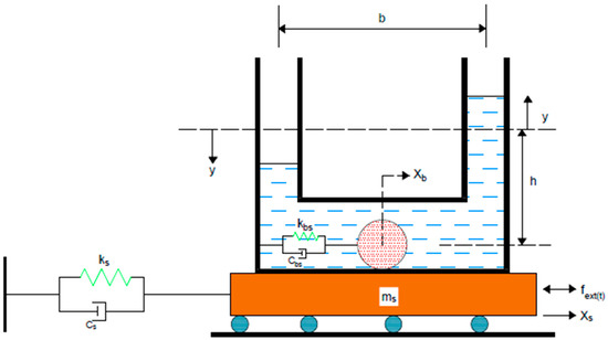
Figure 1.
Structure with a tuned liquid column ball spring sliding damper (TLCBSSD).
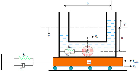
Figure 2.
Structure with a tuned liquid column ball spring rolling damper (TLCBSRD).
2.1.1. Tuned Liquid Column Ball Spring Sliding Damper (TLCBSSD)
The TLCBSSD arrangement the total kinetic energy (T) of the system shown in Figure 1 is given as
where , , and are the kinetic energy of the fluid, primary structure, and ball, respectively.
where and are the fluid volume in the left and right vertical portion of the tube, respectively; is the volume of liquid in the horizontal portion of the tube is the displacement of the primary structure; and is the displacement of the fluid surface. The integration of Equation (2) results in
In Equation (3), is the density of the fluid, is the cross-sectional area of the tube, and h and b are the undisturbed length of fluid in the vertical section and horizontal section of the tube, respectively.
The kinetic energy of the structure is given in Equation (4), where is the mass of the structure attached to the TLCBSSD.
The kinetic energy of the ball is given in Equation (5), where is the mass of the ball.
The total kinetic energy of the system is
The total potential energy (U) of the system is as follows, where ,, and are the potential energy of the fluid, structure, and ball, respectively.
The potential energy associated with the fluid is
Integrating the above Equation (8) leads to
where g is the gravitational acceleration. The potential energy associated with the structure can be expressed as
where is the fundamental stiffness of the structure. The potential energy of the ball can be presented as
where is the stiffness of the spring attached to the ball. Combining Equations (10)–(12) results in
The external and damping forces associated with , y, and are , , and , respectively.
where is the externally applied force on the structure, is the damping coefficient of the structure, is the damping of the fluid interacting with the ball and is found experimentally, is the cross-sectional area of the ball, is the viscous damping coefficient of the spring, and is the equivalent damping coefficient associated with submerged objects in the fluid, and can be expressed as [49]
where is the radius of the ball and v is the coefficient of the absolute viscosity or kinematic viscosity.
where is the fundamental natural frequency of the structure and is the damping ratio of the structure.
where is the mass of the fluid with total length L = 2h + b, and is the natural frequency of the liquid column and is equal to . The damping ratio can be found experimentally.
where is the natural frequency of the ball attached to the spring and is the damping ratio of the spring attached to the ball. The equations of motions are derived using the following Lagrange equation.
where . At i = 1, and , and t = time, the equation results in
where is the length ratio.
When i = 2, and , and t = time, the equation results in
At i = 3, and , and t = time, the equation results in
2.1.2. Tuned Liquid Column Ball Spring Rolling Damper (TLCBSRD)
Considering the TLCBSRD arrangement, the total kinetic energy of the system shown in Figure 2 can be presented as
The and of the TLCBSRD is the same as that of the TLCBSSD. The only difference in the case of the TLCBSRD is the kinetic energy of the ball. In the TLCBSRD configuration the ball possesses both translational and rotational motion. Therefore, the ball has translational and rotational kinetic energies. Assuming no slippage condition, the kinetic energy of the ball can be expressed as
Putting Equations (3), (4) and (27) into Equation (25), the total kinetic energy of TLCBSRD leads to
In the TLCBSRD and TLCBSSD arrangements the potential energy of the system remains the same. So, the potential energy of TLCBSRD is
The external and damping forces associated with , y, and are expressed in Equations (14)–(16), respectively. The equations of motion are derived using Lagrange’s Equation (21). At i = 1, and , and t = time, the equation results in
where is the mass moment of inertia of the ball. At i = 2, and , and t = time, the equation results in
At i = 3, and , and t = time, the equation results in
2.2. Tuned Liquid Column Ball Damper (TLCBD)
The schematic illustration of the TLCBD attached to a single-degree freedom structure is shown in Figure 3.
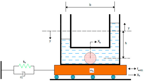
Figure 3.
Structure with the traditional tuned liquid column ball damper (TLCBD).
The TLCBD consists of a U-shaped tube filled with liquid. A solid ball that acts as a moving orifice is placed in the horizontal part of the damper. The equations of motion of the TLCBD are derived using Lagrange’s equation. The total kinetic energy of the system shown in Figure 3 can be presented as
The kinetic energy of the system is the same as that of the TLCSBRD damper arrangement shown in Figure 2.
The total potential energy of the system can be presented as
The and of the TLCBD are equal to both TLCBSSD arrangements. The only difference is the potential energy of the ball. in case of the TLCBD is zero. Therefore, the potential energy of TLCBD is
The external and damping forces associated with , y, and are , , and , respectively.
using Lagrange’s Equation (21).
At i = 1, and , and t = time, the equation results in
At i = 2, and , and t = time, the equation results in
At i = 3, and , and t = time, the equation results in
3. Parameter Optimization
In the present study, the numerical optimization of the TLCBSD was conducted in two stages using the optimum parameters of Al-Saif at el.’s [43] work, as shown in Table 1. In the first stage, the optimum tuning frequency ratio (η = ) of the TLCBD was obtained by solving the equation of motion using the linear state-space representation approach. In the second stage, the optimum tuning frequency ratio obtained in the first stage was used for the TLCBSSD and TLCBSRD to get the optimum tuning frequency of the spring–ball attachment. The optimization was made under harmonic excitations, which is the simplified model for vortex shedding forces on a structure in the crosswind direction.

Table 1.
Optimal design parameters for the tuned liquid column damper.
3.1. Optimization of Tuning Frequency of Liquid Column Ball System
The equations of motion of the TLCBD system shown in Figure 3 were solved numerically using state-space representation at a length ratio of 0.6, 0.7, and 0.8. All three arrangements were investigated in the tuning frequency ratio (η) range of 0.6 to 1.2 under harmonic excitation (). It can be seen in Figure 3 that by increasing the length ratio the response got better at all the tuning frequency ratios. In all the selected length ratios of the TLCBD, the response improvement percentage became almost constant in the tuning frequency range of 0.96 to 1.04, as shown in Table 2. It can also be seen in Figure 4 that the slope of the curve became constant in all three arrangements in the aforementioned tuning frequency range. The maximum response reduction improvement (58%) was achieved at a length ratio = 0.8. Thus, maximum response reduction can be obtained at = 0.8 and η range (0.96 to 1.04).
Table 2.
Percentage improvement of the TLCBD at different length ratios.
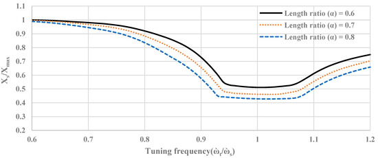
Figure 4.
Normalized response of the tuned liquid column ball damper at different length ratios.
3.2. Optimization of Tuning Frequency of TLCBSD System
In this step, the performance of the TLCBSSD and TLCBSRD were optimized using the primary structure detailed given in Table 1 with an optimal tuning ratio of 0.98 and a length ratio of 0.8. The response of the structures was studied with both the dampers for the optimal tuning frequency of the spring–ball attachment (£ = ) at = 1%, where £ is the ratio of the frequency of the spring–ball system ( to the structure’s natural frequency . It is clear from the response of TLCBSSD, as shown in Figure 5, that for £ values greater than 1.3, the performance became favorable. A significant improvement in the performance was observed at £ = 1.4 onward, whereas in the case of the TLCBSRD (Figure 6), the improvement in the response reduction was prominent at £ values greater than 1.4. The maximum response reduction in the case of the TLCBSRD was at £ = 1.6. It can also be seen in Figure 5 and Figure 6 that at optimal £ values the response of the fluid and ball was comparatively low in both arrangements, with significant response reduction in the primary structure when compared with the ball and fluid arrangement without the spring (£ = 0).
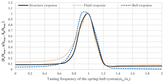
Figure 5.
Normalized displacement of the structure, liquid column, and ball with the TLCBSSD arrangement.
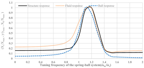
Figure 6.
Normalized displacement of the structure, liquid column, and ball with the TLCBSRD arrangement.
4. Results and Discussion
In this section, the primary structure with optimal parameters tabulated in Table 1 and Table 3 are investigated with the TLCBD, TLCBSSD, and TLCBSRD subjected to harmonic, seismic, and impulsive loadings. The equation of motion of each arrangement was numerically integrated using the linear state-space representation procedure.
Table 3.
Optimal design parameters for the TLCBSSD and TLCBSRD.
4.1. Response of the Structure Subjected to Harmonic Loading
Figure 7 shows the normalized frequency responses of the structure subjected to harmonic loading with and without dampers. The response of the structure improved with the TLCBD, TLCBSSD, and TLCBSRD in the resonance region and was almost constant in the remaining zones. However, the reduction in the response of the structure with the TLCBSSD and TLCBSRD was significantly better than with the TLCBD. The qualitative measure of the responses of the TLCBSSD and TLCBSRD are tabulated in Table 4. It can be observed that the performance of the TLCBSSD and TLCBSRD in the resonance region was around 24% and 25% better over the TLCBD, respectively. The maximum reduction in the response in the TLCBSSD and TLCBSRD over TLCBD was 30% and 32% at wex/ws = 0.9, respectively. The better performance of the TLCBSSD and TLCBSRD compared to the TLCB was due to better energy dissipation mechanisms, because in the case of the TLCBD, the energy was dissipated in three ways: (1) as heat due to friction between the ball and fluid, (2) due to the translational motion of the ball, and (3) due to the rotational motion of the ball. However, in addition to these three ways, the energy in the TLCBSD was also dissipated due to the spring interaction with the ball and fluid.
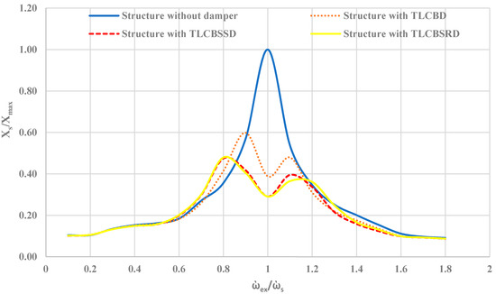
Figure 7.
Normalized frequency responses of the primary structure without a damper, with the TLCBD, with the TLCBSSD, and with the TLCBSRD.
Table 4.
Percentage performance improvement of the TLCBSSD and TLCBSRD over the TLCBD.
4.2. Response of the Structure Subjected to Seismic Excitation
Figure 8a–c shows the displacement time history responses of the structure without a damper, and with the TLCBD, TLCBSSD, and TLCBSRD when subjected to the 1940 EI Centro ground motion. The reduction in peak response of the structure attached with dampers was compared with the response of the structure without a damper. It can be observed in Figure 9 that these dampers reduced the peak displacement response of the structure during seismic excitations. The peak response reduction of the structure with the TLCBSSD and TLCBSRD arrangement was better than the TLCBD arrangement with the structure in all three seismic excitations, as shown in Figure 9. Figure 10 presents the root-mean-square (RMS) displacement response reduction of the structure with the TLCBD, TLCBSSD, and TLCBSRD. The TLCBSSD and TLCBSRD significantly reduced the RMS response of the structure compared to the TLCBD in the case of EI Centro and Hachinohe ground motion excitation. The better performance of the structure with the TLCBSSD and TLCBSRD was due to the additional energy dissipation mechanism of the spring–ball system, whereas in the case of the TLCBD the energy was dissipated only due to friction between the ball and fluid, and due to the translational and rotational motion of the ball [43,44,45]. However, in the case of the Kobe and Kashmir earthquake ground motion, a slight decrease in the RMS response was observed in the TLCBSSD and TLCBSRD compared to the TLCBD. This can be explained in two ways. First, at a high-frequency, low-amplitude signal, the ball inside the TLCBD can move relatively easily compared to the spring-attached ball arrangement of the TLCBSD. Therefore, the TLCBD dissipates energy efficiently compared to the TLCBSD. Second, at very high frequencies there is no significant difference in the response of the TLCBD and TLCBSD, as can be seen in harmonic loading case in Figure 7. To further explain the slight decrease in the RMS response of the TLCBSD compared to the TLCBD, the Fast Fourier Transform spectrum of Kobe and Hachinohe ground motion was developed, as shown in Figure 11. In the case of Kobe, dominant frequencies lay in the range of 1.4 to 2.5 Hz (Figure 11a), whereas in the case of Hachinohe, the dominant frequencies lay in the range of 0.8 to 1.2 Hz (Figure 11b). Therefore, it can be said that the slight difference in response of the TLCBSD and TLCBD under Kobe and Kashmir earthquake ground motion was because of high-frequency, low-amplitude vibrations.
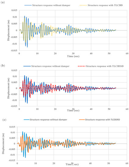
Figure 8.
Time-history responses of the primary structure displacement when subjected to 1940 EI Centro ground motion: (a) comparison between a primary structure with and without a TLCBD, (b) comparison between a primary structure with and without a TLCBSSD, (c) comparison between a primary structure with and without a TLCBSRD.
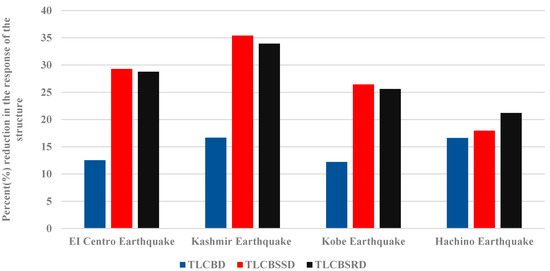
Figure 9.
The percentage reduction in the peak displacement value of the primary structure with different dampers when subjected to 1940 EI Centro, 2005 Kashmir earthquake, 1995 Kobe earthquake, and Hachinohe earthquake ground motion.
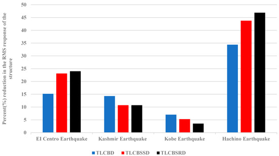
Figure 10.
The percentage reduction in the RMS displacement value of the primary structure with different dampers when subjected to 1940 EI Centro, 2005 Kashmir earthquake, 1995 Kobe earthquake, and Hachinohe earthquake ground motion.
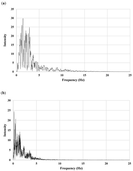
Figure 11.
Fast Fourier Transform spectrum of seismic signals: (a) 1995 Kobe earthquake and (b) Hachinohe earthquake.
4.3. Frequency Domain Response of Structure
To evaluate the structural response in the frequency domain, Fast Fourier Transform (FFT) was applied to the time-domain vibration response of the structure. The response of the uncontrolled structure and the structure with a damper was studied under Kobe and Hachinohe seismic excitation for the frequency domain. In the case of Kobe (Figure 12a), the FFT peak ordinates of the uncontrolled structure appeared near 1 Hz, whereas in the case of the TLCBD, the TLCBSSD and TLCBSRD peak maximum ordinate of FFT shifted to 0.8 Hz. The peak ordinate values of the TLCBD arrangement were suppressed slightly more compared to the TLCBSSD and TLCBSRD. In the case of Hachinohe (Figure 12b), peak ordinates of damper arrangements were suppressed and shifted in the frequency range of 0.50 to 0.55 Hz, whereas peak ordinates for the uncontrolled structure lay in the frequency range of 0.40 to 0.50 Hz. The greater reduction in peak values of FFT ordinates were observed for the TLCBSSD and TLCBSRD compared to the TLCBD arrangement in the case of Hachinohe.
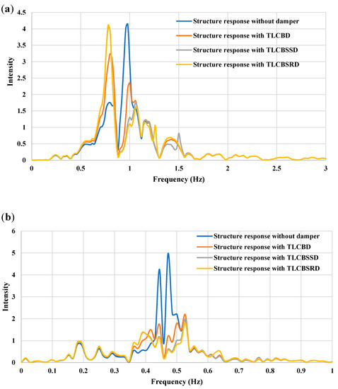
Figure 12.
Frequency domain response of the uncontrolled structure and the structure with a different damper arrangement under seismic excitation: (a) 1995 Kobe earthquake and (b) Hachinohe earthquake.
4.4. Response of the Structure Subjected to Impulsive Loading
A load that is applied for a very short duration is known as impulsive or shock loading. Damping forces are less significant to control the maximum response of the structure during impulsive loading because the maximum response is reached in the impulsive loading in a very short interval. Therefore, damping forces cannot absorb sufficient energy from the structure to reduce its peak response. The efficiency of the dampers attached to the structure was assessed and subjected to triangle impact loading (shown in Figure 13), which is the simplified model for blast loading. Figure 14 shows the structure responses without a damper and with a TLCBD, TLCBSSD, and TLCBSRD. It can be seen in Figure 14d that as the impact load was applied, all the arrangements’ responses reached the peak at once. The damper minimally reduced the initial peak displacement. However, soon after that, all three dampers’ arrangements significantly reduced the subsequent peaks compared to the structure response without a damper. The subsequent peak reduction response of the TLCBSD arrangement was a little better compared to the TLCBD.
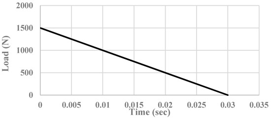
Figure 13.
Triangular impulsive load.
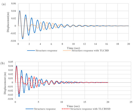
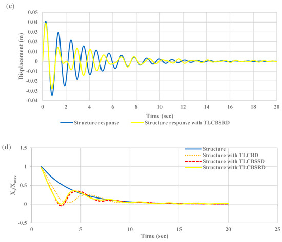
Figure 14.
Time-history responses of the main structure displacement subjected to impulsive loading: (a) structure with and without a TLCBD, (b) structure with and without a TLCBSSD, (c) structure with and without a TLCBSRD, and (d) structure with normalized peak response without a damper, and with a TLCBD, TLCBSSD, and TLCBSRD.
4.5. Design Guidelines for Tunned Liquid Column Ball Spring Damper
Based on the current numerical investigations and the previous literature, the following guidelines are proposed to select the appropriate optimal parameters for the design of TLCBSSDs and TLCBSRDs.
- (1)
- Choose the mass ratio for the liquid portion of the damper (0.5% to 5%) [43]. The higher the mass ratio, the better the efficiency of the damper will be.
- (2)
- For economical design, select a length ratio ά in the range of 0.7 to 0.9 [40].
- (3)
- Select an optimum tuning frequency of the liquid column of the damper in the range of 0.96 to 1.04 (Figure 4)
- (4)
- Find the length of the damper using the chosen optimal tuning frequency.
- (5)
- Find the cross-sectional area of the tube using the length and mass ratio.
- (6)
- For optimum results, take the ball–tube diameter ratio = 0.8 [43].
- (7)
- In the case of a TLCSSD, for optimum results choose a tuning frequency for the spring–ball attachment equal to or greater than 1.4.
- (8)
- For a TLCSRD arrangement, select an optimal tuning frequency for the spring–ball attachment equal to or greater than 1.6.
5. Conclusions
This paper presents the two new modified versions of a tuned liquid column ball damper (TLCBD), known as a tuned liquid column ball spring sliding damper (TLCBSSD) and a tuned liquid column ball spring rolling damper (TLCBSRD). Lagrange’s equations were used to derive the mathematical model of the TLCBSSD and TLCBSRD attached with a single-degree freedom structure. The optimal design parameters of the TLCBD from previous research were used to obtain the optimum design parameters for the newly proposed dampers. The performance of the dampers was evaluated numerically using the obtained optimal design parameters. The response reductions achieved for the structure subjected to harmonic loading with a TLCBSSD and TLCBSRD were 30% and 32%, respectively, compared to the TLCBD in the resonance zone. The TLCBSSD and TLCBSRD, when subjected to historic seismic excitations, also showed better performance compared to the TLCBD. The structural peak response reduction was 29% and 28% with TLCBSD and TLCBRD, respectively, when subjected to 1940 EI Centro seismic excitations, whereas the traditional TLCBD merely reduced the structure response by 12%. In the case of the 2005 Kashmir earthquake, the TLCBSRD reduced the peak displacement response by 35% compared to the primary structure. However, the conventional TLCBD reduced the peak response by 16%. The same trend was observed in the case of the 1995 Kobe and Hachinohe. The RMS response of the structure was reduced by more than 40% in the case of Hachinohe with the TLCBSSD and TLCBSRD. In the case of the impact loading, the peak response reduction was slightly better in the TLCBSRD and TLCBSSD soon after the impact. However, after that, the response reduction of all three dampers was almost the same. Overall, the performance of the newly proposed dampers was comparatively more efficient than the TLCBD. The proposed system can be easily implemented for new dampers as well as for existing dampers. For TLCBD systems, even a slight variation in the vibration frequency causes the ball to hit the walls of the liquid column, which in turn induces additional load on the structure. The proposed system effectively tackles such a possibility.
Author Contributions
Conceptualization: M.U.S. and M.U.; methodology: M.U.S., M.U., S.H.F. and I.-H.K.; validation: M.U. and I.-H.K.; investigation: M.U.S. and M.U.; writing—original draft preparation: M.U.S.; writing—review and editing: M.U., S.H.F. and I.-H.K.; visualization: S.H.F. and I.-H.K.; supervision: M.U. and S.H.F.; project administration, M.U.; funding acquisition I.-H.K. All authors have read and agreed to the published version of the manuscript.
Funding
Basic Science Research Program through the National Research Foundation (NRF) funded by the Ministry of Education (No. NRF-2020R1I1A1A01073676, No. NRF-2021R1A6A1A0304518511).
Institutional Review Board Statement
Not applicable.
Informed Consent Statement
Not applicable.
Data Availability Statement
The data used in this study is available on the request from the corresponding author.
Acknowledgments
This research was supported by Basic Science Research Program through the National Research Foundation (NRF) funded by the Ministry of Education (No. NRF-2020R1I1A1A01073676) and was supported by Basic Science Research Program through the National Research Foundation of Korea (NRF) funded by the Ministry of Education (No. NRF-2021R1A6A1A0304518511).The authors are very thankful to Engr. Ibrahim Sarwar and Engr. Muhammad Hamza Khalid of the National University of Sciences and Technology for their valuable suggestions and help.
Conflicts of Interest
The authors declare no conflict of interest.
Nomenclature
| ms | Mass of the main structure | A | The cross-sectional area of the tube |
| mf | Mass of the fluid | Ab | The cross-sectional area of the ball |
| µ | The ratio of the mass of the fluid to the mass of the structure | The ratio of the horizontal length to the total length of the fluid | |
| Rb | The radius of the ball | deq | Damping due to ball–fluid interaction |
| η | Tuning frequency | Mass moment of inertia of the ball | |
| L | Total liquid length | The density of the fluid | |
| b | Fluid length in horizontal section | h | Undisturbed fluid vertical length |
| Displacement of the main structure | cs | Damping coefficient of the main structure | |
| g | Gravitational acceleration | Damping coefficient of the spring | |
| ks | Primary structure stiffness | The damping ratio of the main structure | |
| kbs | Stiffness of the spring–ball attachment | The damping ratio of the fluid | |
| The natural frequency of the liquid column | The damping ratio of the spring–ball system | ||
| The natural frequency of the main structure | t | Time | |
| The natural frequency of the spring–ball attachment | Ct | Equivalent damping due to fluid–ball interaction | |
| Frequency of the external force | Displacement of the ball | ||
| R | Ball–tube diameter ratio | y | Displacement of the fluid surface |
| Externally applied force | ith generalized forces |
References
- Memon, S.A.; Zain, M.; Zhang, D.; Rehman, S.K.U.; Usman, M.; Lee, D. Emerging trends in the growth of structural systems for tall buildings. J. Struct. Integr. Maint. 2020, 5, 155–170. [Google Scholar] [CrossRef]
- Halis Gunel, M.; Emre Ilgin, H. A proposal for the classification of structural systems of tall buildings. Build. Environ. 2007, 42, 2667–2675. [Google Scholar] [CrossRef]
- Baskaran, A. Wind engineering studies on tall buildings-transitions in research. Build. Environ. 1993, 28, 1–19. [Google Scholar] [CrossRef]
- Zain, M.; Usman, M.; Farooq, S.H.; Mehmood, T. Seismic Vulnerability Assessment of School Buildings in Seismic Zone 4 of Pakistan. Adv. Civ. Eng. 2019, 2019. [Google Scholar] [CrossRef] [Green Version]
- Jafari, M.; Alipour, A. Methodologies to mitigate wind-induced vibration of tall buildings: A state-of-the-art review. J. Build. Eng. 2021, 33, 101582. [Google Scholar] [CrossRef]
- Hafeez, M.A.; Usman, M.; Umer, M.A.; Hanif, A. Recent Progress in Isotropic Magnetorheological Elastomers and Their Properties: A Review. Polymers 2020, 12, 1–37. [Google Scholar]
- Koo, J.H.; Jang, D.D.; Usman, M.; Jung, H.J. A feasibility study on smart base isolation systems using magneto-rheological elastomers. Struct. Eng. Mech. 2009, 32, 755–770. [Google Scholar] [CrossRef]
- Khan, B.L.; Azeem, M.; Usman, M.; Farooq, S.H.; Hanif, A.; Fawad, M. Effect of near and far Field Earthquakes on performance of various base isolation systems. Procedia Struct. Integr. 2019, 18, 108–118. [Google Scholar] [CrossRef]
- Tariq, M.A.; Usman, M.; Farooq, S.H.; Ullah, I.; Hanif, A. Investigation of the structural response of the mre-based mdof isolated structure under historic near- and far-fault earthquake loadings. Appl. Sci. 2021, 11, 2876. [Google Scholar] [CrossRef]
- Khayam, S.U.; Usman, M.; Umer, M.A.; Rafique, A. Development and characterization of a novel hybrid magnetorheological elastomer incorporating micro and nano size iron fillers. Mater. Des. 2020, 192. [Google Scholar] [CrossRef]
- Khan, I.U.; Usman, M.; Tanveer, M. Vibration control of an irregular structure using single and multiple tuned mass dampers. Proc. Inst. Civ. Eng.—Struct. Build. 2021, 12, 1–26. [Google Scholar] [CrossRef]
- Ikeda, Y.; Sasaki, K.; Sakamoto, M.; Kobori, T. Active mass driver system as the first application of active structural control. Earthq. Eng. Struct. Dyn. 2001, 30, 1575–1595. [Google Scholar] [CrossRef]
- Xu, Z.; Guo, Y. Integrated intelligent control analysis on semi-active structures by using magnetorheological dampers. Sci. China Ser. E Technol. Sci. 2008, 51, 2280–2294. [Google Scholar] [CrossRef]
- Park, W.; Park, K.-S.; Koh, H.-M. Active control of large structures using a bilinear pole-shifting transform with H∞ control method. Eng. Struct. 2008, 30, 3336–3344. [Google Scholar] [CrossRef]
- Kim, H.-S. Multi-input Multi-output Semi-active Fuzzy Control of Seismicexcited Building with Evolutionary Optimization Algorithms. Int. J. Control Autom. 2014, 7, 143–152. [Google Scholar] [CrossRef]
- Symans, M.D.; Constantinou, M.C. Semi-active control systems for seismic protection of structures: A state-of-the-art review. Eng. Struct. 1999, 21, 469–487. [Google Scholar] [CrossRef]
- Preumont, A. Vibration Control of Active Structures: An Introduction; Springer: Berlin/Heidelberg, Germany, 2011; Volume 246, pp. 403–416. [Google Scholar] [CrossRef]
- Braz-César, M.; Carneiro De Barros, R. Passive Control of Civil Engineering Structures. In Proceedings of the 4th International Conference on Integrity, Reliability and Failure of Mechanical Systems, Funchal, Portugal, 23–27 June 2013; Volume 1, pp. 1–12. [Google Scholar]
- Zhang, M.; Xu, F. Tuned mass damper for self-excited vibration control: Optimization involving nonlinear aeroelastic effect. J. Wind Eng. Ind. Aerodyn. 2022, 220, 104836. [Google Scholar] [CrossRef]
- Bauer, H.F. Oscillations of immiscible liquids in a rectangular container: A new damper for excited structures. J. Sound Vib. 1984, 93, 117–133. [Google Scholar] [CrossRef]
- Haskett, T.; Breukelman, B.; Robinson, J.; Kottelenberg, J. Tuned Mass Dampers under Excessive Structural Excitation; Report of the Motioneering Inc.: Guelph, ON, Canada, 2004. [Google Scholar]
- Di Matteo, A.; Pirrotta, A.; Tumminelli, S. Combining TMD and TLCD: Analytical and experimental studies. J. Wind Eng. Ind. Aerodyn. 2017, 167, 101–113. [Google Scholar] [CrossRef]
- Sakai, F. Tuned liquid column damper-new type device for suppression of building vibration. In Proceedings of the 1st International Conference on High-rise Buildings, Beijing, China, 1989; pp. 926–931. Available online: http://ci.nii.ac.jp/naid/10007252264/en/ (accessed on 22 April 2021).
- Koh, C.G.; Mahatma, S.; Wang, C.M. Theoretical and experimental studies on rectangular liquid dampers under arbitrary excitations. Earthq. Eng. Struct. Dyn. 1994, 23, 17–31. [Google Scholar] [CrossRef]
- Sun, L.M.; Fujino, Y.; Koga, K. A model of tuned liquid damper for suppressing pitching motions of structures. Earthq. Eng. Struct. Dyn. 1995, 24, 625–636. [Google Scholar] [CrossRef]
- Fujino, Y.; Sun, L.; Pacheco, B.M.; Chaiseri, P. Tuned liquid damper (TLD) for suppressing horizontal motion of structures. J. Eng. Mech. 1992, 118, 2017–2030. [Google Scholar] [CrossRef] [Green Version]
- Xue, S.D.; Ko, J.M.; Xu, Y.L. Optimum parameters of tuned liquid column damper for suppressing pitching vibration of an undamped structure. J. Sound Vib. 2000, 235, 639–653. [Google Scholar] [CrossRef]
- Yalla, S.K.; Kareem, A. Optimum absorber parameters for tuned liquid column dampers. J. Struct. Eng. N. Y. 2000, 126, 906–915. [Google Scholar] [CrossRef]
- Chen, J.-L.; Georgakis, C.T. Spherical tuned liquid damper for vibration control in wind turbines. JVC/J. Vib. Control 2015, 21, 1875–1885. [Google Scholar] [CrossRef]
- Ghosh, A.; Basu, B. Seismic vibration control of short period structures using the liquid column damper. Eng. Struct. 2004, 26, 1905–1913. [Google Scholar] [CrossRef]
- Colwell, S.; Basu, B. Investigations on the performance of a liquid column damper (LCD) with different orifice diameter ratios. Can. J. Civ. Eng. 2011, 33, 588–595. [Google Scholar] [CrossRef]
- Hitchcock, P.A.; Kwok, K.C.S.; Watkins, R.D.; Samali, B. Characteristics of liquid column vibration absorbers (LCVA)—I. Eng. Struct. 1997, 19, 126–134. [Google Scholar] [CrossRef]
- Hitchcock, P.A.; Kwok, K.C.S.; Watkins, R.D.; Samali, B. Characteristics of liquid column vibration absorbers (LCVA)—II. Eng. Struct. 1997, 19, 135–144. [Google Scholar] [CrossRef]
- Chang, C.C.; Hsu, C.T. Control performance of liquid column vibration absorbers. Eng. Struct. 1998, 20, 580–586. [Google Scholar] [CrossRef]
- Gao, H.; Kwok, K.C.S.; Samali, B. Optimization of tuned liquid column dampers. Eng. Struct. 1997, 19, 476–486. [Google Scholar] [CrossRef]
- Huo, L.; Li, H. 13 th World Conference on Earthquake Engineering TORSIONALLY COUPLED RESPONSE CONTROL OF STRUCTURES. In Proceedings of the 13th World Conference on Earthquake Engineering, Vancouver, BC, Canada, 1–6 August 2004. [Google Scholar]
- Das, S.; Choudhury, S. Seismic response control by tuned liquid dampers for low-rise RC frame buildings. Aust. J. Struct. Eng. 2017, 18, 135–145. [Google Scholar] [CrossRef]
- Xin, Y.; Chen, G.; Lou, M. Seismic response control with density-variable tuned liquid dampers. Earthq. Eng. Eng. Vib. 2009, 8, 537–546. [Google Scholar] [CrossRef]
- Debbarma, R.; Chakraborty, S.; Kumar Ghosh, S. Optimum design of tuned liquid column dampers under stochastic earthquake load considering uncertain bounded system parameters. Int. J. Mech. Sci. 2010, 52, 1385–1393. [Google Scholar] [CrossRef]
- Shum, K.M. Closed form optimal solution of a tuned liquid column damper for suppressing harmonic vibration of structures. Eng. Struct. 2009, 31, 84–92. [Google Scholar] [CrossRef]
- Wu, J.C.; Shih, M.H.; Lin, Y.Y.; Shen, Y.C. Design guidelines for tuned liquid column damper for structures responding to wind. Eng. Struct. 2005, 27, 1893–1905. [Google Scholar] [CrossRef]
- Shum, K.M.; Xu, Y.L.; Guo, W.H. Wind-induced vibration control of long span cable-stayed bridges using multiple pressurized tuned liquid column dampers. J. Wind Eng. Ind. Aerodyn. 2008, 96, 166–192. [Google Scholar] [CrossRef]
- Al-Saif, K.A.; Aldakkan, K.A.; Foda, M.A. Modified liquid column damper for vibration control of structures. Int. J. Mech. Sci. 2011, 53, 505–512. [Google Scholar] [CrossRef]
- Tanveer, M.; Usman, M.; Khan, I.U.; Ahmad, S.; Hanif, A.; Farooq, S.H. Application of tuned liquid column ball damper (TLCBD) for improved vibration control performance of multi-storey structure. PLoS ONE 2019, 14, 1–15. [Google Scholar] [CrossRef] [PubMed]
- Tanveer, M.; Usman, M.; Khan, I.U.; Farooq, S.H.; Hanif, A. Material optimization of tuned liquid column ball damper (TLCBD) for the vibration control of multi-storey structure using various liquid and ball densities. J. Build. Eng. 2020, 32, 101742. [Google Scholar] [CrossRef]
- Gur, S.; Roy, K.; Mishra, S.K. Tuned liquid column ball damper for seismic vibration control. Struct. Control Health Monit. 2015, 22, 1325–1342. [Google Scholar] [CrossRef]
- Pal, S.; Roy, B.K.; Choudhury, S. Comparative performance study of tuned liquid column ball damper for excessive liquid displacement on response reduction of structure. Int. J. Eng. Trans. B Appl. 2020, 33, 753–759. [Google Scholar] [CrossRef]
- Shah, M.U.; Usman, M. Feasibility Study of Liquid Tuned Column Hollow Ball Damper for Vibration Control of Structures. In Proceedings of the 2021 World Congress on Advances in Structural Engineering and Mechanics (ASEM21), GECE, Seoul, Korea, 23–26 August 2021; pp. 1–13. [Google Scholar]
- Streeter, V.L.; Wylie, E.B. Fluid Mechanics, 7th ed.; McGraw-Hill: New York, NY, USA, 1979; ISBN 0070622329. [Google Scholar]
Publisher’s Note: MDPI stays neutral with regard to jurisdictional claims in published maps and institutional affiliations. |
© 2021 by the authors. Licensee MDPI, Basel, Switzerland. This article is an open access article distributed under the terms and conditions of the Creative Commons Attribution (CC BY) license (https://creativecommons.org/licenses/by/4.0/).