Abstract
A complete set of diverse haptic feedbacks is essential for a highly realistic and immersive virtual environment. In this sense, a multi-mode haptic interface that simultaneously generates multiple kinds of haptic signals is highly desirable. In this paper, we propose a new silicone-made pneumatically controlled fingertip actuator to render pressure and vibrotactile feedback concurrently to offer a realistic and effective haptic sensation. A new silicone-based stacked dual-layer air chamber was designed. The volume of the chambers is controlled by pneumatic valves with compressed air tanks. The top/upper air chamber renders vibration feedback, whereas the bottom/lower air chamber renders pressure feedback. The proposed silicone-made fingertip actuator is designed so that it can be easily worn at the fingertips. To demonstrate the potential of the system, a virtual environment for rendering three different types of haptic textures was implemented. Extensive performance evaluation and user studies were carried out to demonstrate the proposed actuator’s effectiveness compared to an actuator with single vibrotactile feedback.
1. Introduction
Virtual reality (VR) enables users to experience real events without actually being in the situation [1]. The core enabling technology for VR is software and hardware components for synthesizing appropriate physical signals for our five senses, which mimics the signals generated during real interactions. Due to recent advances in computer graphics and immersive visual display technology, the fidelity of visual feedback is reaching the level of the Turing test where a normal human can hardly distinguish between real and synthesized scenes [2]. The fidelity of haptic feedback, however, is still quite inferior to that of visual feedback in most VR systems [3], which is one of the areas that needs a technological breakthrough in VR [4].
Tactile feedback is one of the inevitable haptic modalities that can recreate the sense of touch. It provides the perception of pressure, vibration, and shear force [3]. Usual haptic interaction involves all types of tactile sensations, and thus, a haptic system should provide different tactile sensations for high-fidelity virtual interaction. However, most existing tactile actuators are operated based on electromagnetic principles [5,6], and the feedback is rendered using pin arrays, voice coil actuators, linear resonant actuators, push–pull solenoid valves, etc. [7,8]. Tactile sensations can be easily perceived using small actuators that are feasible to attach to and carry on the user’s body [5]. However, the main drawback of these devices is that they can render only a single kind of feedback using a single module. Integrating multiple actuators can be a straightforward solution to overcome this issue. However, using multiple actuators can make the system heavy and limit usability, notably when wearability is the foremost concern.
A multi-mode haptic actuator can be a solution to overcome the aforementioned issue. It has already been proven that a pneumatically controlled soft actuator can provide high-frequency vibrotactile feedback and pressure feedback with a single actuator [9]. Furthermore, it offers various functional advantages, which include lightweightness, flexibility, high strain density, and ease of fabrication as per the desired shape [10,11]. It also performs a significant role in robotics, medical training, and telerobotics. Osgouei et al [12] developed a soft pneumatic active actuator to mimic human sphincter muscles and simulate various anal sphincter tones for medical training. However, the main drawback of these works is that they rendered one kind of feedback at a time due to a simplified design, i.e., the single bladder design of the end effector.
To overcome this issue, in this paper, we propose a dual-layer silicone-made fingertip actuator that provides both vibrotactile feedback and pressure feedback simultaneously. The proposed actuator consists of dual air chambers stacked on each another. The top/upper air chamber generates vibrotactile feedback, whereas the bottom/lower air chamber produces pressure feedback. The actuator was designed considering the shape of the users’ fingertips having an average thickness so that it can be easily wearable on the index finger of the users. Although different fingertip sizes may affect the result of the experiment, it is manageable to construct new actuators of different sizes for users have diverse fingertip thicknesses. It lets the user direct contact at his/her fingers to minimize the constraint of hand movement [13]. The system renders realistic sensations with a pressure feedback of 5.5 N at 6 psi air pressure and 0.13 g vibration feedback along the z-axis. We further present a proof-of-concept rendering algorithm that shows the applicability of the new design.
The major contributions of this work are summarized as follows.
- A soft actuator for simultaneous pressure and vibration feedback rendering on a human fingertip;
- Two different actuators, i.e., a silicone-made fingertip actuator with simultaneous feedback and a silicone-made fingertip actuator with single feedback, were used;
- A virtual environment combined with a haptic interface utilized for texture rendering experience;
- User studies were performed to demonstrate the similarity rating and subjective evaluation of the proposed actuator. In addition, penetration depth analysis was conducted to evaluate the performance of the proposed actuator.
The rest of the paper is organized as follows. Section 2 highlights the related literature in the field of multi-mode haptic feedback. Section 3 describes the design and fabrication of our proposed actuator. Section 4 describes the hardware control of our fingertip actuator. Section 5 discusses details about the pneumatic control algorithm for the VR framework using our proposed actuator. Section 6 discusses the evaluation of the rendering capabilities of the system. Lastly, we conclude our contribution in Section 7.
2. Related Work
Our proposed fingertip pneumatic actuator renders two different types of feedback simultaneously, i.e., pressure and vibrotactile feedback. Previously, many systems have been proposed to provide such multi-mode haptic feedback using multiple actuators in a single system. In this section, we describe the existing works that are closely related to our approaches.
2.1. Multi-Mode Haptic Feedback Using Multiple Actuators
The most common way to realize multi-mode tactile feedback has been combining multiple actuators. For instance, a finger wearable device was designed by Chen et al., which produced three types of feedback simultaneously [14]. The device rendered normal force, lateral force, and vibrotactile force feedback for the interaction of the finger and the touch screen through three internally integrated actuators. An MR foam actuator was integrated to provide normal force feedback, while the piezoelectric actuator was integrated to generate vibrotactile feedback. The lateral force feedback was provided by a DC motor and a friction wheel. As another example, a fingertip haptic display was developed to provide integrated force, tactile, and thermal feedback [15]. They used two DC motors and a Peltier module to generate the sensations. Park et al. designed a hybrid device that rendered multi-modal stimuli. They utilized a haptuator to render vibrotactile feedback, while a 1-DoF impact actuator to render impact feedback [16]. On the other hand, an underground augmented reality system was designed to alter the roughness and friction of a rigid 3D object [17]. A vibration waveform was generated to model the texture roughness. However, it was generated by using a voice coil actuator. To render friction, a solenoid inside the stylus applies force to the ball.
Several studies have focused on combining pneumatic feedback with other kinds of technologies. To this end, Premarathna et al. presented a soft tactile display that produces force and vibration feedback using a pneumatic balloon and electromagnetic coil [18]. A haptic device was also designed to show the impact of simultaneously applying normal stress and vibrotactile stimulation [19]. They used a piston with a DC motor to apply normal force to the skin and two shaftless cylindrical vibrator motors to generate vibrotactile stimulus. Another example is a hybrid electromagnetic–pneumatic actuation system that was used to apply the tactile stimulus and a Peltier element attached to the display to render thermal stimulus [20]. Uddin et al. [21] introduced a portable haptic glove that provided both force and tactile feedback. A double-acting pneumatic cylinder was used to produce force feedback. It was operated by using solenoid DC valves through the pulse-width modulation technique. Chen et al. developed a haptic interface to show the virtual interactive information through multi-mode haptic feedback [22]. A piston-type magnetorheological actuator and a voice coil actuator were combined to form a hybrid actuator that rendered force feedback. In contrast, a linear resonant actuator was utilized to generate vibrotactile feedback. On the other hand, a touch screen was developed that allowed the user to simultaneously feel both large bumps and small textures [23]. They employed lateral force to feel the shape and mechanical vibration to feel the texture.
A common shortcoming of combining multiple actuators for delivering different modalities of haptic feedback is that the whole haptic system becomes bulky and impractical, thus hindering fine haptic experience.
2.2. Pneumatically Controlled Multi-Mode Haptic Feedback
There have been attempts to produce different kinds of feedback with a single actuator. Yoshida et al. [24] proposed a pneumatically controlled complex haptic device with a dual-layered air structure to control both the reaction force and 3D concave deformation. They used a solid elevating part between two elastic stretchable layers to form the actuator. The finger deformation was controlled by the upper air layer, and the reaction force applied to the finger was controlled by the bottom air layer. The device was capable of rendering the realistic hardness and softness of soft surfaces. Talhan et al. [9] proposed a pneumatic ring-shaped finger-worn actuator that provided multi-mode haptic feedback consecutively in a VR or AR environment. They utilized a single air chamber between the stretchable and non-stretchable membrane to render haptic feedback. The actuator generated three distinctive haptic effects, such as static pressure, high-frequency vibration, and impact. Similarly, Hassan et al. [25] designed a pneumatically controlled haptic mouse that also rendered static pressure, high-frequency vibration, and impact response separately. The haptic mouse consisted of two air housings. The inside housing was non-stretchable to hold the shape of the mouse, while the outside housing was stretchable to deliver the haptic feedback directly on the user’s hand. He et al. [26] developed a pneumatic control arm-worn band that rendered different types of tactile feedback at different times. However, they focused on tapping, holding, and tracing sensations to generate different haptic cues using five air chambers. Tapping was rendered by inflating and deflating one air chamber; holding occurred when some or all the air chambers inflated at the same time. The tracing sensation was simulated by inflating an array of air chambers in sequence. Huaroto et al. [27] designed a soft pneumatic actuator incorporated into a prosthetic limb. They utilized a sheet of nylon ripstop fabric between two silicone layer to make the air chamber. The actuator rendered vibration and tapping feedback separately according to its application. On the other hand, Youn et al. [28] proposed a soft actuator incorporating a dielectric elastomer actuator covered by a silicone elastomer membrane. The actuator was capable of rendering pressure and vibration feedback separately.
Although the single actuator approach improves practicality, existing works have been unable to simultaneously generate multi-mode feedback, resulting in reduced realism.
The common factor among all the aforementioned systems is that either they used multiple actuators (end effectors) for delivering different modalities of haptic feedback or delivered feedback iteratively. Our proposed system can deliver multiple haptic feedback simultaneously using the same actuator.
3. Silicone-Made Fingertip Actuator Design and Fabrication
The main focus of this system is to generate simultaneous multi-modal feedback using only a single wearable actuator. Among different body parts, we chose the fingertip as it is one of the haptically most sensitive parts of the human body. Unlike our earlier approach to create a multi-mode haptic actuator, this time, we focused on the most effective finger wearable shape: a fingertip shape. We selected a fingertip-shaped end effector as a haptic interface due to two main reasons: (i) the prominent role of fingertips while exploring an object and (ii) the most efficient way to wrap the fingertip without extra holding attachments. We chose a soft bladder-based pneumatic actuation among several tactile actuation technologies, because it was found that the just-noticeable difference (JND) in softness is approximately for the bare finger and for a finger wearing a thin soft glove, while the JND performance decreases to approximately when the finger operates from inside a rigid thimble [29]. This approach also possesses several other advantages. First, pneumatic actuation allows us to separate the end effector that touches the skin from the source of power. Since the fingertip cannot sustain a large weight, this advantage plays a vital role to increase usability. Second, a soft and flexible material can further increase wearability. This section describes our design choices and the manufacturing procedure of the actuator.
3.1. Material Selection and Molding Process
The material selected to mold the proposed device was Ecoflex 00-30 (smooth-on, Inc.: Macungie, Pennsylvania, PA, USA) (Young’s modulus = 0.1694136 MPa, Shore hardness = 00-30). Ecoflex silicone has a modulus of 10 psig and a elongation at break, making for an extremely flexible and resilient surface. Because of its high malleability, it is easy to shape according to its use.
To design the new actuator, a significant molding process was carried out, as shown in Figure 1. This is the process of creating a new object using liquid or malleable material with a high melting point. A specific mold was used, which was made of either metal or plastic. There was a hollow cavity where the liquid material was poured. After pouring the liquid material, it was required to wait until the liquid solidified. The mold itself was made using a model of the final object. Our final mold was made of acrylonitrile butadiene styrene (ABS) material in the shape of our fingertip actuator.
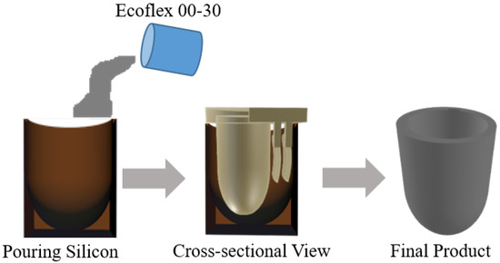
Figure 1.
Molding process to manufacture the actuator.
The final actuator was a fingertip-shaped object designed to be worn on the index finger, which consisted of two movable molds. The inside movable mold was used to make the inside cavity of the final object, while the outside mold held the shape of the final object. The mold was printed using a 3D printer. Liquid silicone was poured into the holding container, and the moveable part was pressed into it, as shown in Figure 1. The silicone solidified into the shape of the movable part.
3.2. Multi-Mode Actuator Design Model
In order to deliver vibration and pressure at the same time, we propose a dual-layer silicone-made fingertip actuator. The two air chambers in the two-layer separately take charge of different feedback. The top/upper air chamber generates vibrotactile feedback, while the bottom/lower air chamber is responsible for pressure feedback. The two-layer structure was further designed in a way that it could be worn on the fingertip as a thimble. The actuator is flexible and light weight, minimizing the constraint on hand movement.
Figure 2 shows the design of our proposed silicone-made fingertip actuator. The actuator is divided into two distinct air chambers for two different kinds of feedback. The outside wall of the actuator is kept non-stretchable to keep the original shape of the actuator, while the inside wall is stretchable to render haptic feedback. The non-stretchable layer was achieved by adding fiber-based tissue during the silicone molding process. The air chambers are situated between the walls of the actuator. Additionally, two pneumatic pipes were attached to the two air chambers. One is for rendering pressure feedback, and the other one is for rendering vibrotactile feedback. Each pipe was then connected to one positive and one negative solenoid valve. The positive valve is used for inlet air from the air reservoir, and the negative valve is used for exhaust air.
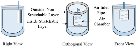
Figure 2.
Design and structure of the actuator.
4. Hardware Control
The actuator is mainly controlled by pneumatic actuation. It is required to inflate and deflate the air chambers of the actuator in a systematic way to render a specific kind of feedback. By controlling the amount of air inside the air chambers, it is possible to control the pressure and vibration feedback of the actuator.
The hardware used in this system is shown in Figure 3. To control the flow of air inside the air chambers, we used four electrically controlled air solenoid valves (SC0526GC; Skoocom Technology Co. Ltd.: Shenzhen, Guangdong, China) for the two air chambers. Two of the valves were used as positive ones, and the other two were used as negative ones. By using positive solenoid valves, air fills the chamber from the air source, while the negative solenoid valves are used to exhaust air to the environment. A diode (1N4007) was used with each solenoid valve to control and eliminate the transient voltage when the magnetic coil of the solenoid valves suddenly loses power. A 16 g threaded CO cartridge from TRAVELO was used as an air source. The Arduino Uno micro-controller was used for maintaining the serial communication of the computer and actuator. The digital input from the computer goes to the MOSFET transistor circuit through the Arduino using serial communication. By controlling the air solenoid valves, specific haptic feedback is rendered. The chambers of the actuator inflate when air is pumped inside, while they deflate when air is exhausted. The pressure regulator used for our actuator ranges from 0 psi to 30 psi. However, we used air pressure in the range of 5 psi to 10 psi.
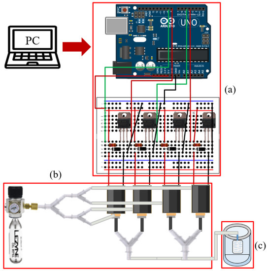
Figure 3.
Hardware component for pneumatically controlling the actuator. (a) Electronics including the micro-controller, (b) the air cartridge with solenoid valves and silicone tube, and (c) the silicone-made pneumatic fingertip actuator.
5. Rendering Textured Surface with Vibration and Pressure
As an example of maximizing the effectiveness of the dual-layer design, we introduced a new textured surface rendering algorithm optimized for our actuator. When a rigid texture surface is touched and explored, a user will feel not only the quasi-static pressure due to the rigidity of the surface, but also the vibrotactile feedback coming from the roughness of the surface during stroking for exploration. The two different kinds of tactile feedback come simultaneously, so they should be rendered simultaneously in a virtual environment for high realism. This section details the rendering algorithm and control schemes for the realistic rendering of the two simultaneous feedbacks.
The finger of the user is tracked to experience interaction. The rendering algorithm presents the texture-rendering process using our silicone-made fingertip actuator. The algorithm constantly tracks the contact between the virtual objects and the user’s 3D finger model inside the VR environment.
Figure 4 demonstrates our overall proposed framework for texture rendering using the proposed actuator. In this work, the VR environment was designed using the Unity game engine (2019). Virtual textured surfaces are rendered in the VR environment, where users can explore them graphically and haptically. The user’s finger is tracked using an optical tracker (OptiTrack Trio, V120, NaturalPoint, Inc., Corvallis, OR, USA [30]), and the user’s tracked finger are virtually drawn in the scene.
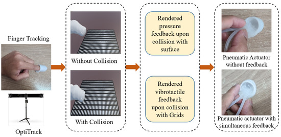
Figure 4.
Proposed framework for haptic texture rendering.
As examples, three haptically distinctive virtual texture surfaces were designed. These surfaces were bumpy surface (Type A), uniform grid surface (Type B), and non-uniform grid surface (Type C), the same as the real surfaces presented in Figure 5. When the user moves his or her finger on the top of the surface, vibration and pressure feedback are rendered. The pressure feedback is rendered when the user comes into contact with the surface until they remove their finger from the surface, which provides a feeling of rigidity. At the same time, vibrotactile feedback is rendered in response to the user’s movement during contact, representing the roughness resulting from collisions of the user’s fingertip with the extruding asperities or particles of the surface.
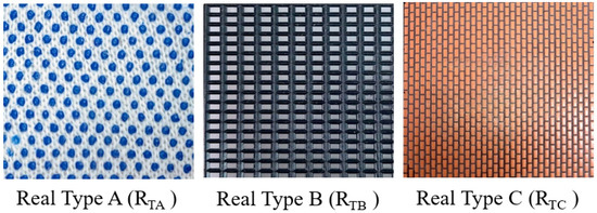
Figure 5.
Different types of texture surfaces used for texture rendering.
In order to incorporate the material differences of the surfaces in rendering, we introduced a grid-based vibration rendering. The surface has a regular virtual “grid” on its surface. When the user’s fingertip hits one of the grids, one cycle of vibration is rendered. On the one hand, the difference in the density of the surface micro asperities is simulated by the spatial frequency of the grid. The larger gap among grids generates vibration at a lower frequency, resulting in the surface being felt as sparser and vice versa. On the other hand, the difference in the roughness of the surface is represented by the height of the grids. Grids with a higher height generate vibration with higher amplitude, making rougher surfaces and vice versa. Finally, we carefully tuned the spatial frequency and the height of the grid for the three surfaces so that they best mimicked the real surfaces.
The scenes of the virtual environment used in our experiments are demonstrated in Figure 6.
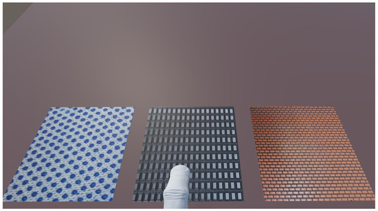
Figure 6.
The scenes of the virtual environment used in our experiments.
We also measured the rendered simultaneous feedback for the texture surfaces. Figure 7 shows examples of rendered accelerations for the three surfaces. We collected the acceleration data using a three-axis accelerometer module (GY-61 DXL335; Analog Devices, Inc.: Wilmington, MA, USA). The differences are clearly seen in the frequency spectrum graph.

Figure 7.
Rendered simultaneous pressure and vibration feedback for Type A, Type B, and Type C Surfaces in the time and single-sided frequency domain.
First, a virtual surface is graphically rendered on a computer screen. The user can interact with this surface using the tracked 3D finger model. The whole rendering system is provided in Algorithm 1, where Px,y,z denotes the tracked finger position in 3D space, Lx,y,z denotes one of the predefined texture surface locations in 3D space, R3 denotes the predefined location of three texture surfaces, S denotes any surface in the VR environment, Is denotes the interacted surface, and Ts denotes the predefined texture surface. The algorithm constantly tracks any contact between the finger model and the virtual surface. A collision event is triggered in case of contact between the finger model and the surface. During the collision, pressure feedback is presented for the feeling of rigidity using the air chamber at the lower layer. When the user’s lateral movement hits one of the grids, a thread is created for each unit of the grids. For every thread, a single vibrotactile signal is generated using the upper layer air chamber for texture rendering. The algorithm sends an opening command to appropriate valves for the two air chambers, generating actual feedback.
| Algorithm 1 Texture-rendering process |
|
6. Evaluation
This section presents the experimental evaluation of the proposed actuator. The whole experiment was divided into a performance evaluation and three user studies: similarity rating, penetration depth error analysis, and subjective evaluation.
6.1. Performance Evaluation
The first experiment was designed to evaluate the ability of the actuator to produce pressure and vibration feedback. A series of measurement experiments were conducted, and the results were analyzed. We first characterize the frequency response of the actuator, followed by the characterization of the pressure response.
6.1.1. Vibration Feedback Measurement
In order to validate the fabricated fingertip actuator for frequency response, a test for vibrations was carried out. To render vibration feedback, we need to make a continuous displacement of the upper air chamber of the actuator. By repeatedly opening and closing the solenoid valves, the air travels inside the air chamber and exhausts from the air chamber. This type of continuous airflow makes the vibration-like frequency of the air chamber. This vibration frequency gives the user vibration feedback. We can control the frequency of the vibration by controlling the on and off cycle with a delay. The air chamber is able to vibrate at different frequencies (from 1 Hz to 100 Hz).
A three-axis accelerometer module (GY-61 DXL335; Analog Devices, Inc.: Wilmington, MA, USA) was used to measure the vibrations of the air chamber. We obtained the vibration data using a data acquisition device (NI- DAQ USB-6009, National Instrument, Inc.: Austin, TX, USA). Subsequently, the collected data were analyzed using MATLAB in the time and frequency domains. In order to convert the time domain signal into the frequency domain, the fast Fourier transform was used. A dataset of 3000 measurements was collected with a 1000 Hz sampling rate for 3 s. The time and frequency domain analyses for 5 Hz, 25 Hz, and 50 Hz are shown in Figure 8.

Figure 8.
Examples of rendered vibration feedback in the time and single-sided frequency domains.
6.1.2. Pressure Feedback Measurement
A high-precision force sensor (Nano 17, ATI Industrial Automation, Apex, NC, USA) was used to measure the pressure applied by the actuator. The inlet air pressure can be increased by using the pressure-regulated valves that were connected to the pneumatic tubes. The force sensor was attached to the top air chamber of the actuator, and a fixture was used to prevent the relative motion between the force sensor and the actuator. The actuator generates a 5.5 N force at the finger within 500 ms. Figure 9 shows the force magnitude changes vs. valve opening duration.
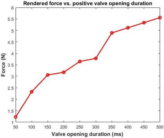
Figure 9.
Rendered force vs. positive valve opening duration.
6.2. User Study 1: Similarity Rating
The second experiment was designed to evaluate the realism of the feedback by assessing the perceptual similarity between virtual and real texture surfaces. The accuracy of virtual feedback was evaluated by comparing its feedback with the corresponding real feedback.
6.2.1. Participants
We invited fifteen participants (eight males and seven females) for the experiment. Their average age was 26 (22–30 years old). Among them, six had no experience of haptic rendering, and nine had general knowledge of haptic rendering.
6.2.2. Experimental Design
In this experiment, the participants interacted with the corresponding pair of real and virtual texture surfaces shown in Figure 5 and Figure 6, and they were asked to rate the overall haptic similarity between the virtually textured surfaces and corresponding real surfaces. The participants interacted with the virtual texture surfaces using our dual-layered actuator. The actuator was worn on the participants’ index fingers.
The real texture materials were subjectively selected from real-life textured surfaces. Then, the surfaces were glued to rigid acrylic plates (100 × 100 × 5 mm) [31]. Three corresponding virtual texture surfaces with a similar hardness were also prepared using the same design as the real ones. The real textures surfaces are designated as RTA, RTB, and RTC (Figure 5), while the virtual texture surfaces as VTA, VTB, and VTC (Figure 6). Eight different comparisons were performed for each participant in total. The first three pairs were real–virtual texture surfaces of the same type (VTA–RTA, VTB–RTB, VTC–RTC). The second three conditions were pairs of real–real texture surfaces of the same type (RTA–RTA, RTB–RTB, RTC–RTC). These three comparisons were presented to determine the upper bound of the similarity ratings. Determining the upper bound can be helpful for the participants to remember the reference. We presented the last two conditions with completely different feedback (RTA–RTB, VTA–VTB) to find out the lower bound of the similarity ratings.
6.2.3. Procedure
Before starting the experiment, the participants were instructed about the procedure. We confirmed that the participants correctly understood the procedure by asking them to repeat the instructions. The experiment was divided into a training and main session. In the training session, the participants were introduced to using the actuators and interacting with the texture surfaces. In particular, the participants experienced the process of moving fingers by wearing the actuators in front of the position tracker.
In the main session, distracting auditory and visual cues were prevented by blindfolds and headphones with white noise (Figure 10). For each participant, we presented all pairs of texture samples (real and virtual) randomly. The participants experienced all the samples and reported the similarity ratings to the operator. During the experiment, the participants sensed the real surfaces with bare fingers, while the virtual surfaces with the proposed actuator. The participants were asked to rate the overall similarity result on a scale from 0–100. The participants could rate zero if they felt completely different feedback and one-hundred if they felt two identical feedbacks. Each comparison was repeated two times, yielding 16 (=) similarity ratings per participant. For each participant, it took about 30 min to complete the entire experiment.
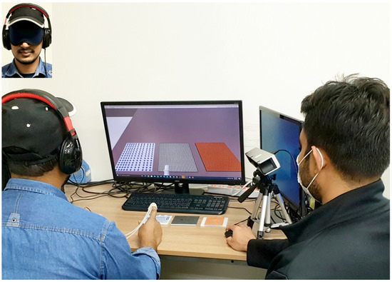
Figure 10.
Similarity experiment. The participant compares a real–virtual pair of objects. The operator sitting to the right of the participant replaces the real and virtual samples and records the reported similarity ratings.
After the experiment, the participants were instructed to answer a short questionnaire with the four questions depicted in Table 1. This questionnaire was also used to determine third-party factors affecting the perceived realism.

Table 1.
Questionnaire for the post-experiment interview.
6.2.4. Results and Discussion
The experimental results are plotted in Figure 11 for the eight comparisons. The condition RTA–RTA showed the highest rating among all real–real pairs (). The average similarity scores for the three real–real pairs were used as the upper reference. The lower bound’s similarity score was selected using the average score of the two lower references. The highest-rated pair of real–virtual texture surfaces VTA–RTA had a score of , whereas the lowest was for VTC–RTC. This result indicates that the haptic similarity between the virtual surface generated by our system and the corresponding real surface was quite comparable to the similarity between two real surfaces. In other words, the realism of the virtual feedback was not very inferior to the realism of the real feedback.
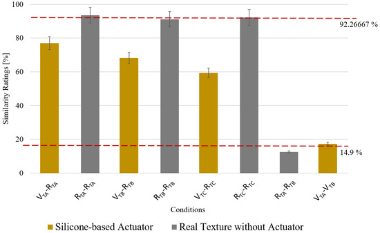
Figure 11.
Average similarity scores from the similarity experiment. The error bars show the standard error. Note that V represents virtual, R real, TA Type A, TB Type B, and TC Type C.
These results can be considered promising since the feedback for the virtual surface completely lacked kinesthetic information, while the real ones had it. Achieving realism only with tactile feedback in a rigid surface exploration task can be considered encouraging. Nevertheless, our approach tried to indirectly mimic this kinesthetic feedback of rigidity using the pressure feedback based on the dual-layer design, and the effect of our new design was evaluated in the following User Study 2.
6.3. User Study 2: Testing the Feeling of a Rigid Surface
The third experiment was designed to evaluate how our simultaneous feedback helps to improve the quality of feedback. As mentioned in Section 5, the example application we implemented tried to replace the feeling of supporting a rigid surface by quasi-static pressure feedback while providing the texture rendering with vibrotactile feedback. In this experiment, we investigated the effect of this additional pressure feedback on the user-perceived rigidity.
6.3.1. Experimental Design
In this experiment, the participants were presented two rendering algorithms to feel the surface: one with both vibrotactile and pressure and the other with only vibrotactile. They were asked to freely explore the surface with both algorithms. Our hypothesis is that if there is additional pressure feedback during contact, the user would have additional feeling or information of the contact, resulting in less penetration of the virtual surface during the exploration.
A subset of 10 participants from the previous experiment took part in this experiment. In this experiment, the participants interacted with the three virtual texture surfaces shown in Figure 6 based on the two different rendering methods (“vibration-only” and “vibration+pressure”) for five seconds. For each surface, two explorations using the two methods were repeated two times, yielding a total of 12 explorations per participant. During the interaction, the user’s fingertip position was collected using the external optical tracker.
6.3.2. Experimental Procedure
Before starting the experiment, the participants were instructed about the procedure. We confirmed that participants correctly understood the procedure by asking them to repeat the instructions. This experiment was also divided into training and main sessions. In the training session, the participants were introduced to the two different types of feedback.
In the main session, the participants were again blindfolded and sound-blocked. The participants explored each sample using the “vibration-only” method and the “vibration+pressure” method two times. The order of the method was kept random. For each participant, it took about 30 min to complete the entire experiment.
6.3.3. Result and Discussion
After the experiment, the penetration depth was calculated for each exploration. It was calculated by finding the maximum distance of the user’s fingertip position from the position of the virtual surface.
The means of the maximum penetration depth for the conditions are plotted in Figure 12. As expected, the penetration depth with “vibration+pressure” showed less penetration depth for all three surfaces. A two-way ANOVA test revealed a significant difference in penetration depth between the two rendering methods (p = 0.0002).
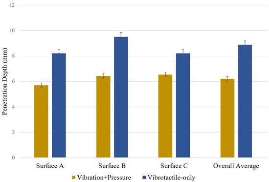
Figure 12.
Mean of maximum penetration depth. The error bars show the standard error.
The results indicated that the additional pressure feedback indeed helped the user to stop his/her further movement through the surface. We speculate that the pressure feedback synchronized with the contact event provides a natural confirmation of contact to the participants, resulting in less penetration depth. It indirectly demonstrated the effectiveness of the simultaneous feedback on realism.
6.4. User Study 3: Overall Realism
In the fourth experiment, we directly tested the subjective realism of the feedback. Here, again, the realism of the “vibration+pressure” method is compared with the “vibration-only” method.
6.4.1. Experimental Design and Procedure
This experiment had the same participants as User Study 2. The same procedure and stimuli were used as User Study 2. The only change was that the participants were asked to rate the overall feedback fidelity after freely exploring the surfaces in this experiment. The participants were asked to report the overall fidelity ratings to the operator by answering how realistic the feedback was (realism) on a scale from 0–100.
6.4.2. Result and Discussion
The mean scores for the questionnaire are plotted in Figure 13. The Type B surface using simultaneous feedback achieved the maximum score of 81.5, followed by the Type-C and Type-A surfaces. Again, the actuator with single vibrotactile feedback showed less fidelity for all three types of surfaces. The two-way ANOVA test showed a significant difference for the two methods (p = 5.9 × 10).

Figure 13.
Mean scores for the realism. The error bars show the standard error.
With the result from User Study 2, this experiment’s results clearly showed that the additional pressure feedback improved the overall quality of the feedback. In particular, the dual-layered design in our new actuator enabled simultaneous feedback, making this improvement possible.
7. Conclusions
In this study, we proposed a new silicone-made fingertip actuator to render realistic haptic feedback. The actuator consisted of dual air chambers that could change their size according to the desired haptic feedback. The proposed actuator enables rendering simultaneous haptic feedback, i.e., pressure and vibration. It helps users perceive realistic texture feedback by simultaneously rendering pressure and vibration feedback. It can easily be built into various sizes according to the user’s finger size. By controlling the amount of air inside the air chambers, it is possible to control the pressure and vibration feedback of the actuator. The quantitative results measured for virtual texture surfaces depicted satisfactory values. Our new approach can be an alternative solution for wearable haptic devices that usually lack the capability of providing kinesthetic feedback.
The actuator can be utilized in other research also. It can be applicable for medical training purposes to train medical students and nurses and also in the rehabilitation sectors to help the patients improve their fingers’ mechanoreceptor stimuli based on feeling different types of texture surfaces.
In this study, we did not consider the change of pressure according to the depth of force applied on the surfaces. We will consider the variable pressure feedback and perform extensive numerical analysis for our future work.
Author Contributions
Conceptualization, M.S.H. and S.J.; methodology, M.S.H., J.B.J. and W.H.; software, M.S.H.; validation, M.S.H., J.B.J. and S.J.; formal analysis, M.S.H.; investigation, M.S.H. and W.H.; resources, S.J.; data curation, M.S.H.; writing—original draft preparation, M.S.H.; writing—review and editing, J.B.J., W.H. and S.J.; visualization, M.S.H. and W.H.; supervision, S.J.; project administration, S.J.; funding acquisition, S.J. All authors have read and agreed to the published version of the manuscript.
Funding
This research was supported by the Preventive Safety Service Technology Development Program funded by the Korean Ministry of Interior and Safety under Grant 2019-MOIS34-001.
Institutional Review Board Statement
Not applicable.
Informed Consent Statement
Not applicable.
Data Availability Statement
Not applicable.
Conflicts of Interest
The authors declare no conflict of interest. The funders had no role in the design of the study; in the collection, analyses, or interpretation of data; in the writing of the manuscript; nor in the decision to publish the results.
References
- Cipresso, P.; Giglioli, I.A.C.; Raya, M.A.; Riva, G. The Past, Present, and Future of Virtual and Augmented Reality Research: A Network and Cluster Analysis of the Literature. Front. Psychol. 2018, 9, 2086. [Google Scholar] [CrossRef] [PubMed] [Green Version]
- Günther, S.; Schön, D.; Müller, F.; Mühlhäuser, M.; Schmitz, M. PneumoVolley: Pressure-based Haptic Feedback on the Head through Pneumatic Actuation. In Proceedings of the ACM Conference on Human Factors in Computer System, Honolulu, HI, USA, 25–30 April 2020; pp. 1–10. [Google Scholar]
- Culbertson, H.; Schorr, S.B.; Okamura, A.M. Haptics: The Present and Future of Artificial Touch Sensation. Annu. Rev. Control. Robot. Auton. Syst. 2018, 1, 385–409. [Google Scholar] [CrossRef]
- Talhan, A.; Jeon, S. Pneumatic Actuation in Haptic-Enabled Medical Simulators: A Review. IEEE Access 2018, 6, 3184–3200. [Google Scholar] [CrossRef]
- Choi, S.; Kuchenbecker, K.J. Vibrotactile Display: Perception, Technology, and Applications. Proc. IEEE 2013, 101, 2093–2104. [Google Scholar] [CrossRef]
- Yao, H.-Y.; Hayward, V. Design and analysis of a recoil-type vibrotactile transducer. J. Acoust. Soc. Am. 2010, 128, 619–627. [Google Scholar] [CrossRef] [PubMed]
- Hiki, K.; Okano, T.; Sakurai, S.; Nojima, T.; Kitazaki, M.; Ikei, Y.; Hirota, K. Substitution of Hand-Object Pressure Cues with the Sole of the Foot for Haptic Presentation Using a Tactile Pin Array. In Proceedings of the International Conference on Human Haptic Sensing and Touch Enabled Computer Applications, Pisa, Italy, 13–16 June 2018; Volume 10894, pp. 239–251. [Google Scholar]
- Otaduy, M.A.; Okamura, A.; Subramanian, S. Haptic technologies for direct touch in virtual reality. In International Association for Computing Machinery’s Special Interest Group on Computer Graphics; ACM: New York, NY, USA, 2016; pp. 1–123. [Google Scholar]
- Talhan, A.; Kim, H.; Jeon, S. Tactile Ring: Multi-mode Finger-Worn Soft Actuator for Rich Haptic Feedback. IEEE Access 2020, 8, 957–966. [Google Scholar] [CrossRef]
- Sasaki, D.; Noritsugu, T.; Takaiwa, M. Development of Active Support Splint driven by Pneumatic Soft Actuator (ASSIST). In Proceedings of the IEEE International Conference on Robotics and Automation, Barcelona, Spain, 18–22 April 2005; pp. 520–525. [Google Scholar]
- Miriyev, A.; Stack, K.; Lipson, H. Soft material for soft actuators. Nat. Commun. 2017, 8, 1–8. [Google Scholar]
- Osgouei, R.H.; Marechal, L.; Kontovounisios, C.; Bello, F. Soft Pneumatic Actuator for Rendering Anal Sphincter Tone. IEEE Trans. Haptics 2020, 13, 183–190. [Google Scholar] [CrossRef] [PubMed]
- Park, J.; Son, B.; Han, I.; Lee, W. Effect of Cutaneous Feedback on the Perception of Virtual Object Weight during Manipulation. Sci. Rep. 2020, 10, 1–10. [Google Scholar]
- Chen, D.; Song, A.; Tian, L.; Fu, L.; Zeng, H. FW-Touch: A Finger Wearable Haptic Interface With an MR Foam Actuator for Displaying Surface Material Properties on a Touch Screen. IEEE Trans. Haptics 2019, 12, 281–294. [Google Scholar] [CrossRef]
- Murakami, T.; Person, T.; Fernando, C.L.; Minamizawa, K. Altered Touch: Miniature haptic display with force, thermal and tactile feedback for augmented haptics. In International Association for Computing Machinery’s Special Interest Group on Computer Graphics; ACM: New York, NY, USA, 2017. [Google Scholar]
- Park, C.; Park, J.; Oh, S.; Choi, S. Realistic Haptic Rendering of Collision Effects Using Multimodal Vibrotactile and Impact Feedback. In Proceedings of the IEEE World Haptics Conference, Tokyo, Japan, 9–12 July 2019. [Google Scholar]
- Culbertson, H.; Kuchenbecker, K.J. Ungrounded Haptic Augmented Reality System for Displaying Roughness and Friction. IEEE/ASME Trans. Mechatron. 2017, 22, 1839–1849. [Google Scholar] [CrossRef]
- Premarathna, C.P.; Chathuranga, D.S.; Lalitharatne, T.D. Fabrication of a soft tactile display based on pneumatic balloon actuators and voice voils: Evaluation of force and vibration sensations. In Proceedings of the IEEE/SICE International Symposium on System Integration (SII), Taipei, Taiwan, 11–14 December 2017; pp. 763–768. [Google Scholar]
- Motamedi, M.R.; Otis, M.; Duchaine, V. The Impact of Simultaneously Applying Normal Stress and Vibrotactile Stimulation for Feedback of Exteroceptive Information. ASME J. Biomech. Eng. 2017, 139, 061004. [Google Scholar] [CrossRef]
- Gallo, S.; Son, C.; Lee, H.J.; Bleuler, H.; Cho, I.-J. A flexible multi-modal tactile display for delivering shape and material information. Sens. Actuators A Phys. 2015, 236, 180–189. [Google Scholar] [CrossRef]
- Uddin, M.W.; Zhang, X.; Wang, D. A Pneumatic-Driven Haptic Glove with Force and Tactile feedback. In Proceedings of the International Conference on Virtual Reality and Visualization, Hangzhou, China, 24–26 September 2016; pp. 304–311. [Google Scholar]
- Chen, D.; Song, A.; Tian, L.; Yu, Y.; Zhu, L. MH-Pen: A Pen-Type Multi-Mode Haptic Interface for Touch Screens Interaction. IEEE Trans. Haptics 2018, 11, 555–567. [Google Scholar] [CrossRef] [PubMed]
- Saga, S.; Raskar, R. Simultaneous geometry and texture display based on lateral force for touchscreen. In Proceedings of the IEEE World Haptics Conference, Daejeon, Korea, 14–17 April 2013. [Google Scholar]
- Yoshida, K.; Suzuki, H.; Abe, H.; Ono, A.; Kawaguchi, H.; Sato, M.; Komoriya, Y.; Ohkuri, K. Pneumatic Concave Deformable Device and Finger Deformation-Based Evaluation for Hardness Perception. In Proceedings of the IEEE World Haptics Conference, Montreal, QC, Canada, 6–9 July 2021. [Google Scholar]
- Hassan, W.; Kim, H.; Talhan, A.; Jeon, S. A Pneumatically-Actuated Mouse for Delivering Multimodal Haptic Feedback. Appl. Sci. 2020, 10, 5611. [Google Scholar] [CrossRef]
- He, L.; Xu, C.; Xu, D.; Brill, R. PneuHaptic: Delivering haptic cues with a pneumatic armband. In Proceedings of the International Symposium on Wearable Computers, Osaka, Japan, 7–11 September 2015; pp. 47–48. [Google Scholar]
- Huaroto, J.J.; Suarez, E.; Krebs, H.I.; Marasco, P.D.; Vela, E.A. A Soft Pneumatic Actuator as a Haptic Wearable Device for Upper Limb Amputees: Toward a Soft Robotic Liner. IEEE Robot. Autom. Lett. 2019, 4, 17–24. [Google Scholar] [CrossRef]
- Youn, J.-H.; Mun, H.; Kyung, K.-U. A Wearable Soft Tactile Actuator With High Output Force for Fingertip Interaction. IEEE Access 2021, 9, 30206–30215. [Google Scholar] [CrossRef]
- Kuchenbecker, K.J.; Ferguson, D.; Kutzer, M.; Moses, M.; Okamura, A.M. The Touch Thimble: Providing Fingertip Contact Feedback During Point-Force Haptic Interaction. In Proceedings of the International Symposium on Haptic Interfaces for Virtual Environment and Teleoperator Systems, Reno, NV, USA, 13–14 March 2008; pp. 239–246. [Google Scholar]
- OptiTrack V120. Available online: https://optitrack.com/products/v120-trio/ (accessed on 5 September 2018).
- Hassan, W.; Abdulali, A.; Abdullah, M.; Ahn, S.C.; Jeon, S. Towards Universal Haptic Library: Library-Based Haptic Texture Assignment Using Image Texture and Perceptual Space. IEEE Trans. Haptics 2018, 11, 291–303. [Google Scholar] [CrossRef] [PubMed]
Publisher’s Note: MDPI stays neutral with regard to jurisdictional claims in published maps and institutional affiliations. |
© 2021 by the authors. Licensee MDPI, Basel, Switzerland. This article is an open access article distributed under the terms and conditions of the Creative Commons Attribution (CC BY) license (https://creativecommons.org/licenses/by/4.0/).