1. Introduction
Automated Driving Systems (ADSs) offer such conceivable benefits as efficient time management, intensive use of vehicle infrastructure, labour cost savings, congestion reduction, environmental benefits and, above all, a reduced number of accidents, of which
(
) are caused by drivers [
1]. Furthermore, the annual consumer and societal benefits of the AVs are estimated to reach
$800 billion by 2050 [
2]. Nevertheless, further development of automated driving systems relies on the advancements of scientific disciplines and new technologies. While the combination of accumulated knowledge in vehicle dynamics, the emergence of deep learning and the availability of new sensor modalities catalysed AVs research, the challenges of fail-operational architectural models and robust perception are yet to be solved [
3].
Initially, the public experienced autonomous driving through the pioneering road-following vehicle Alvin in 1985 developed in the Autonomous Land Vehicle (ALV) project [
4]. The simple “Red minus Blue” segmentation algorithm achieved autonomy for 4.2 km on a gravel road. Further large scale automated driving studies were carried in Europe’s Eureka project PROMETHEUS between 1987 and 1995. The project led to the development of VITA II by Daimler-Benz, which succeeded in automatically driving on highways [
3,
5]. Since the first automated driving challenge organized by the US Department of Defense in 2004—
Defense Advanced Research Projects Agency’s (DARPA) Grand Challenge, autonomous driving has become a lasting research topic. Despite famous claims that fully autonomous driving will be available in 2017, the set goal was not achieved and might be delayed for another decade [
6,
7].
Notably, the complexity of ADSs operation in indeterminate environments raises the challenge of diverse weather conditions and a need to account for agent behaviour, especially in busy urban environments, where autonomous vehicles have advantages over human drivers [
8]. Furthermore, failure to correctly address these challenges has led to accidents that undermine public acceptance of ADSs [
3]. In the attempt to reflect lessons learned from various stakeholders, the
Society of Automotive Engineers (SAE) defined six levels of driving autonomy where level
zero stands for no autonomy and levels
four and
five stand for autonomy where no human interaction is required [
9]. Furthermore, the autonomous systems and their design process must comply with functional safety requirements, i.e., ISO26262 [
10].
A solution for addressing safety requirements and achieving high levels of autonomy is the development of perception systems based on multi-modal sensor data fusion using fail-operational architectures. Data fusion enables the collection and association of different sensor data streams to obtain a combined improved representation compared to using the sensors individually. Realizing fail-operational urban surround perception is the joined objective of the authors, and the presented work tackles this challenge at different levels.
The work presented in this article represents the European H2020 ECSEL project: Programmable Systems for Intelligence in Automobiles (PRYSTINE). The PRYSTINE project accomplishes Fail-operational Urban Surround perceptION (FUSION) based on reliable camera, RADAR and LIDAR sensor fusion and control functions to enable safe automated driving in urban and rural environments. The intermediate overall results of the project previously have been published in [
11,
12,
13].
This article is structured as follows.
Section 2 introduces the developed FUSION solutions for high-performance control and intelligence.
Section 3 investigates fail-operational architectures—Simplex, 1-out-of-2 with diagnostics (1oo2d) and hybrid—and their implications for SAE levels and standardisation.
Section 4 describes the EDI DbW car and its perception system.
Section 5 demonstrates autonomous passenger vehicle for low-speed autonomy and presents results from an autonomous parking scenario.
Section 6 offers a trust model for processing multi-modal sensor data.
Section 7 examines the achieved results and concludes the article.
2. High Performance Embedded Control and Intelligence for FUSION
This paper presents research and development results related to dependable system architectures combining pioneering sensor fusion and AI-supported decision-making approaches realized on a system level for FUSION. The main objective was to design a reliable embedded control and intelligence on a system level. By co-integration of signal processing and AI-supported approaches for FUSION, i.e., pushing the technological capabilities for Automated Driving Systems from SAE Level 3 and beyond the implementation of fail-operational mechanisms for embedded control and enhancing sensor fusion by cameras, LIDAR, RADAR, and implementing decision-making algorithms was completed.
The first solution, a fail-operational autonomous driving platform, exploits Commercial-Off-The-Shelf (COTS) components and Deterministic Ethernet backbone network to design a functionally safe architecture and to enable low-latency data exchange. This demonstrator by TTTech Group and Infineon Technologies AG describes a modular mixed-criticality architecture approach and deploys the implemented fail-over mechanism to perform sensor fusion for automated driving. A shared platform concept allows for integrating multiple services with different certification assurance levels for a modular certification. This flexible and safe architecture runs a fail-over mechanism, which guarantees a service hand-over time to a redundant unit in the order of 80 milliseconds.
The second approach is about a novel AI-based perception system able to perform data fusion, processing and decision-making. The available frameworks for distributed platform development (system and inter-system wise) lack congruent solutions that enable real-time performance based on advanced software component management and intercommunication frameworks. The focus of the research and development of the Institute of Electronics and Computer Science (EDI) is to showcase a novel approach to software component integration using within the PRYSTINE project developed COMPAGE framework (fail-operational system component management framework) and AI-based algorithms capable of identifying faulty sensors by analyzing data of different types, e.g., LIDAR, RADAR, cameras and integrated into a KIA SOUL EV passenger vehicle.
The third demonstrator delivers an SAE Level 3+ equivalent autonomous parking solution and prototype FUSION algorithms for low-speed autonomy by Virtual Vehicle Research GmbH. Advancement beyond the state-of-the-art for this demo, which is related to Automated Parking Valet Systems, mainly originates from the provision of fail-operationality and robustness in perception through the utilization and fusion of multiple sensor modalities, including cameras, LIDAR and RADAR. The focus is on evaluating existing AI algorithms for benchmarking purposes and transferring technologies into the FORD heavy-duty vehicle.
The final demonstrator describes a driver monitoring subsystem that guarantees an accurate traffic movement to increase security threat detection and prevention and improve data reliability. This solution proposes a fully integrated security engineering process for realizing secure automated driving. The University of Turku finalized a fall-back mechanism through integrated fail-operational middleware, which detects fault and security incidents using a firewall.
3. Fail-Operational Architectures
Fail-operational architectures, regardless of the application domain, are very frequently covered in the literature [
14,
15,
16]. Applying those architectures in the automotive domain for enabling autonomous driving functions is not that common. In particular. a classification regarding SAE levels of safety integrity levels is missing most of the time. However, there is still a lot of research published regarding architectures in the automotive domain on the system level, but often purely from the software perspective.
The Simplex architecture [
14] is a popular approach in literature to be used in safety-critical environments in general, but not specifically addressing the automotive domain. There are several contributions and improvements available. In [
14], the simplex architecture is used in a safety-critical environment, using COTS products. A detailed fault study and investigation regarding the stability region of the controlled system is provided by Seto and Shain [
17]. Further investigation regarding limiting fault-propagation in the simplex architecture is done in [
18]. In [
19], hardware/software co-design is used to fulfil fail-operational requirements on the system level.
The 1-out-of-2 with diagnostics (1oo2D) approach is investigated in [
20]. In this paper, the recovery process is accelerated by using state backup and partial hot-standby approaches. Three replication methods were evaluated and considered feasible for fail-operational applications in the automotive domain.
A Hybrid architecture is proposed in [
21]. The authors use primary self-checking and secondary limp-home controllers to enable fail-operational behaviour. As an alternative to hardware-based fault detection mechanisms (e.g., lock-stepping), software-based measures are proposed to detect and mask hardware failures. It is of interest because non-deterministic behaviour, introduced by the new features of high-performance CPUs, contradict some hardware-based diagnostic methods.
Some fault-tolerant software architectures are investigated in [
22]. The authors compare three architectures and check their applicability to the automotive domain. The software architectures investigated in detail are “single version fault topology”, “N-version programming” and “N self-checking programming”. One approach to reducing hardware redundancy utilizes coded processing proposed in [
23]. It is achieved by specific coding of data or instructions, which adds redundancy on a software level.
A software platform to enable fault-detection and fail-operational capabilities is proposed in [
15]. The
SafeAdapt platform is based on AUTOSAR [
24], where the main component, “Safe adaption platform core”, is implemented as a complex device driver. Platform-specific functionality like task activation or deactivation and fault-detection is provided. The platform enables exchanging the status of software components in a heartbeat approach, which enables fail-over mechanisms and hence fail-operational behaviour.
To recover from faults, restart-based approaches also exist. One of them is proposed in [
16]. The authors are introducing a fault-recovery mechanism based on a simplex architecture. If a fault is detected via a monitoring component, a restart of the platform recovers the system. The authors apply methods like a specific schedulability analysis to prove that timing constraints are fulfilled even when system restarts are applied.
According to the state-of-the-art research, there is still a need for further research to create high-performance computing platforms able to host applications targeting SAE levels 3+. There is a lot of research done on module and component levels in hardware and software that might be used in an integrated system. What was missing and covered within this project is the development of a computing platform, fulfilling requirements enabling to host autonomous driving functions on the one hand and considering safety and dependability attributes on the other hand by applying already investigated patterns, e.g., on system architecture level.
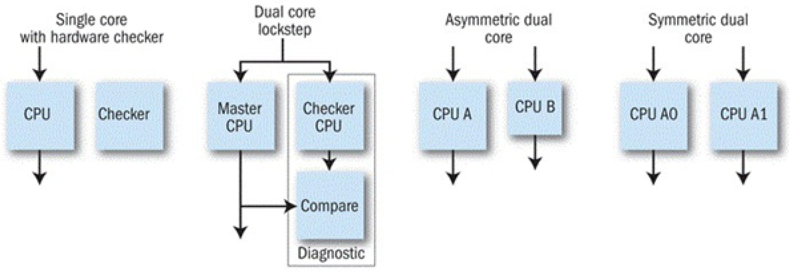
A variety of architectures have evolved over the years to provide an independent mechanism in processor-based systems for detecting failures during runtime. These architectures rely on the use of a single processor with a hardware checker and the use of two processors with the second processor of the same or different type as the main unit. The secondary processor can operate independently, running the same or independent software, serving as a touchstone to validate the primary processor’s behaviour on a cycle-by-cycle basis. The more popular alternative is for the second processor to run in lockstep with the primary unit, using the same code and data. However, the secondary processor will typically work with a slight delay from the primary to avoid having both processors affected by a transient error on the system bus. A variety of architectures have evolved over the years to provide an independent mechanism in processor-based systems for detecting failures during runtime, see
Figure 1.
These architectures share a need to make substantial extensions to the basic processor design, including comparison hardware and possibly a full secondary processor. Furthermore, the external power supply and the internal function blocks need to be investigated for safe operation. The introduction of the AURIX safety controller, among others, opened an opportunity for silicon vendors to offload much of this hardware design burden from system developers. Many safety processors are marketed primarily to automotive designers working under the ISO 26262 standard for ASIL (automotive safety integrity level) certification but are equally applicable to other safety-critical applications in industrial control, medical, military, and aerospace. Nevertheless, the fail-operational requirements cause a need for improvement of the design. Consecutively, the detailed investigation of the advanced ADAS fusion platform based on Aurix 2nd generation safety controller is applicable for the improvement and design of the next-generation safety controller developed in the PRYSTINE project.
Within the PRYSTINE project, Infineon Technologies AG (IFAG) works together with TTTech Group (TTTech) to implement a safe design based on traceability that would provide support for obtaining subsequent safety certification, thus improving the overall design cycle. However, one of the key challenges is to choose a proper safety controller. Therefore, TTTech and IFAG collaborated to develop the HW concept of the ADAS platform, the development of which was further done by TTTech.
To enable automated driving functions, targeting SAE levels 3+, high-performance computing platforms with significantly high reliability and availability are fundamental components. The challenge in this area is mainly to find the optimal compromise between low costs and a sufficient level of dependability as opposed to the aerospace domain, where the expenses for safety and reliability enabling components are of lesser interest due to a significantly lower number of units. Therefore, the architectural patterns (e.g., triple modular redundancy) for highly reliable computing cannot be simply re-used from the aerospace domain.
As previously mentioned, suitable architectures for a fail-operational computing platform in the automotive domain are:
The investigations of the three different architectures are based on a clear distinction between the item (computing platform) and the environment (power supply, sensor, actuator). Furthermore, some basic requirements and assumptions are formulated in
Table 1:
The assumed computing platform in this chapter consists of three identified main components: power management, controller and external communication. The computing platform forms a single fault containment unit because the controller and communication components both are dependent on the power management component. It is mitigated by adding a certain degree of redundancy, which is covered by the three fail-operational architectures.
Basic assumptions for further investigations of the different architectures for a prototypical implementation of the computing platform are the following:
All fault containment units fail independently;
All fault containment units fail in the most restrictive manner, i.e., fail-silent;
All fault containment units can fail in an arbitrary failure mode, as long as all other assumptions are not violated.
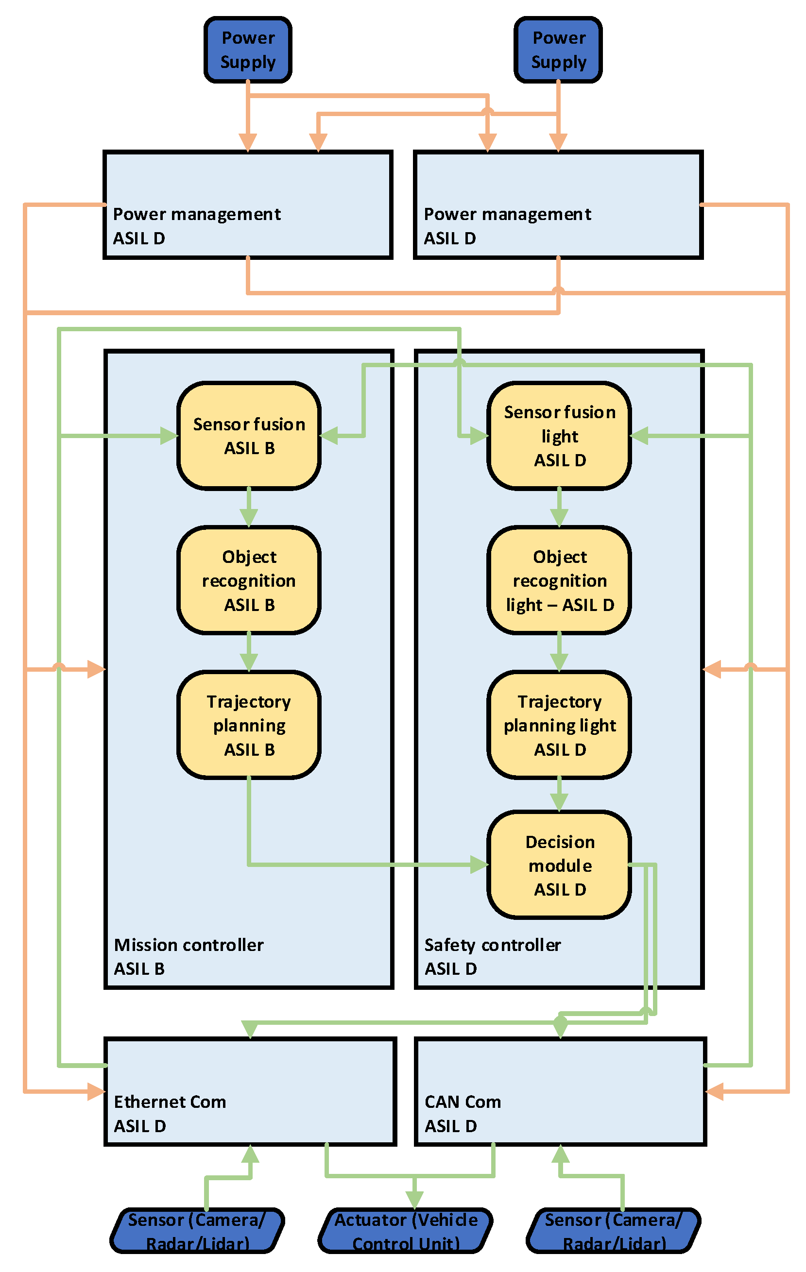
Based on the defined requirements and assumptions, further investigation is done for each of the three architectures. The first architecture, Simplex architecture, originally evolved from control engineering and utilizes two controllers. The high-performance mission controller performs the main functionality, e.g., executing AI algorithms for sensor fusion, object recognition and trajectory planning, while the less powerful safety controller performs evaluation and forwards it to the external communication interfaces. The data are evaluated by a decision module inside the safety controller and requires some reference, e.g., calculated by simpler versions of the AI algorithms (sensor fusion, object recognition and trajectory planning). Since AI algorithms are mostly non-deterministic, this issue of replica non-determinism must be mitigated and considered at the algorithm level (solving the problem of replica non-determinism was not the scope of our investigations). The redundancy ensures that, if the mission controller fails, the safety controller still provides results and ensures that the system is operational. However, the results then are of lower quality because of the lower computational power of the safety controller—the functionality of the system is degraded. In
Figure 2, the power supply and sensor sets (RADAR, LIDAR, camera) are redundant to mitigate a single point of failures. The sensor data are sent to the controllers via diverse communication channels, thus mitigating systematic faults. The most restricting weakness of this architecture is the safety controller being the single point of failure, which potentially can break down the entire system. Even if the safety controller has a very high safety integrity level (e.g., ASIL D), the simplex architecture is not an advisable choice for creating fail-operational computing platforms to enable autonomous driving functions for SAE levels equal to or higher than 3.
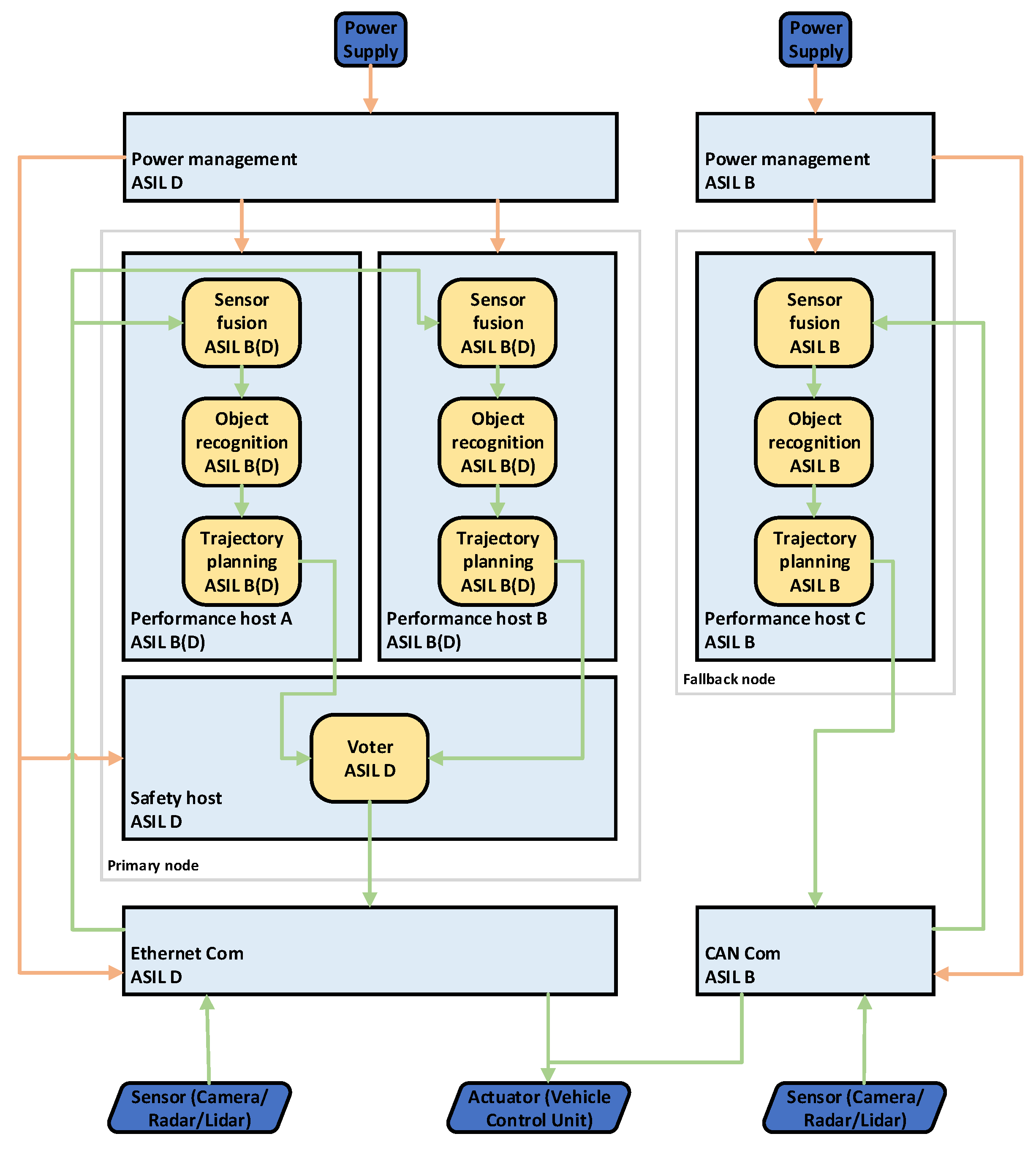
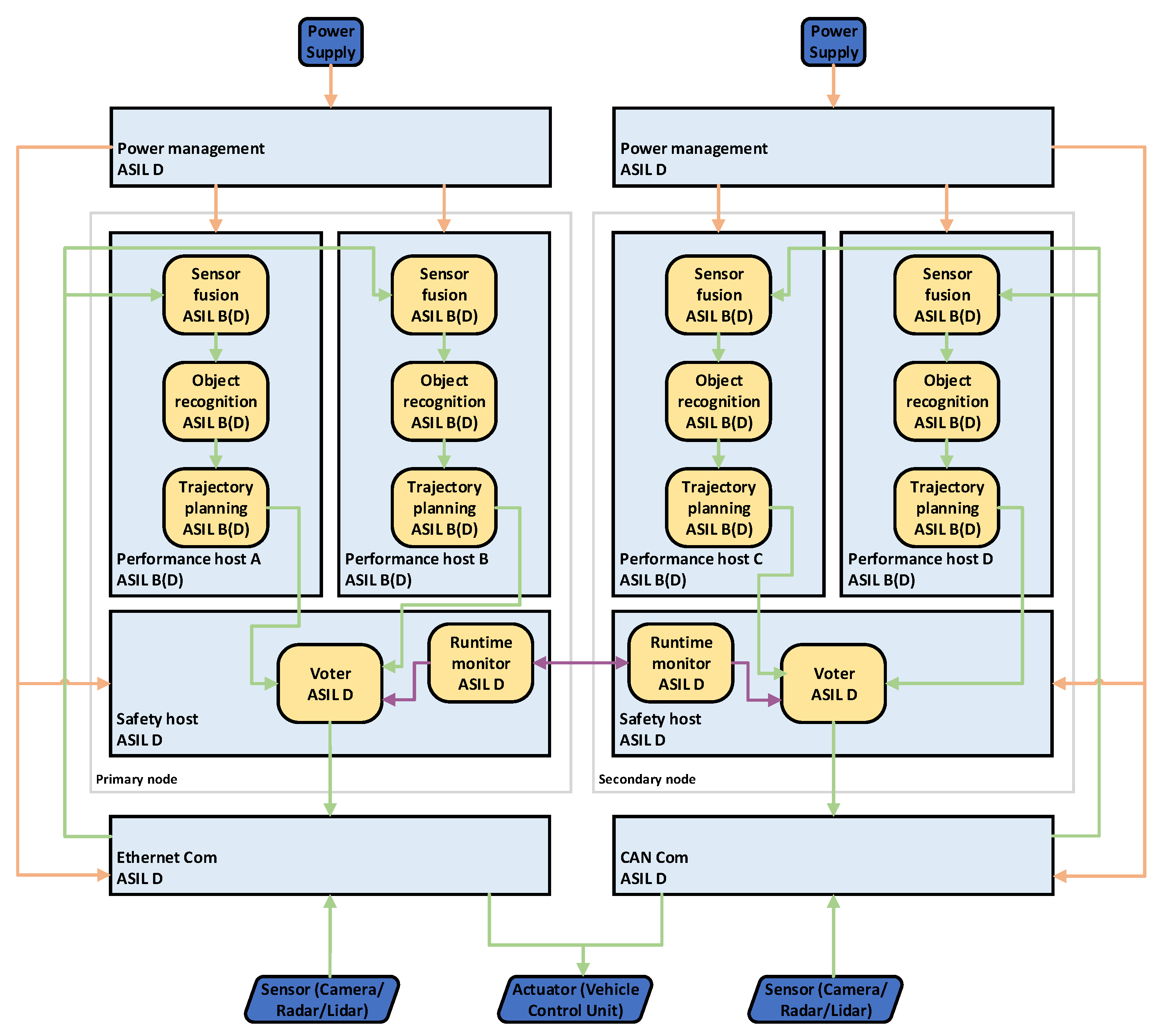
The second architecture to be investigated is 1-out-of-2 with diagnostics (1oo2d) shown in
Figure 3. It uses homogeneous redundancy, consisting of two equally structured nodes, a primary and a secondary one. Each node uses two performance hosts of lower safety integrity levels (e.g., ASIL B) but with higher computational capacity and a safety host with a higher safety integrity level (e.g., ASIL D). The hosting of computationally-intensive ASIL D applications requires ASIL decomposition. ASIL D can be decomposed into 2× ASIL B components as long as a sufficient degree of independence among the hosting components (performance hosts) is ensured. From the perspective of AI algorithms, again, the problem of replica non-determinism between the calculations on performance host A (C on a secondary node) and performance host B (D on a secondary node) must be mitigated.
A voter on the safety host on both nodes is responsible for comparing the results of the AI algorithms and forwarding them to a communication link in case no error has occurred. The runtime monitors on both safety hosts exchange diagnostics information of the nodes and decide which node is currently responsible for sending data. Furthermore, monitors must ensure that always just one node is active, requiring the definition of a specific fail-over mechanism. In this approach, a heartbeat mechanism would be one possible solution, where both runtime monitors exchange periodic heartbeats to check whether the other node is still alive and working correctly.
Errors, having consequences on the operation of any node, must be communicated accordingly, and proper mitigation measures, e.g., maintenance, must be initiated. However, the second node still ensures a certain amount of safe operation time without degrading the functionality. The systematic software and hardware faults can be avoided by ensuring sufficient diversity in the AI algorithms and the development of performance hosts. The 1oo2D architecture is much more complex compared to the simplex architecture and is capable of servicing functionality necessary for SAE levels 3+.
The Hybrid architecture is simpler compared to the 1oo2d approach but more complex compared to the simplex architecture, see
Figure 4. It uses heterogeneous redundancy where the primary and fallback nodes are composed differently. The primary node is equal to any of the nodes in the 1oo2D approach but without a runtime monitor component. The fallback node consists just of a performance host. Diversity among all performance hosts and AI algorithms must be ensured to mitigate systematic hardware and software faults. The failovers in this approach are managed implicitly by the actuator, which means that both nodes (primary and fallback) are always sending their calculated results to the actuator. The actuator uses the results of the primary node as long as they are available. If the primary node switches to a safe state due to an error, the actuator uses the results from the fallback node.
The hybrid architecture ensures the hosting of applications for SAE levels 3+. However, due to the simplicity of the fallback node, operation time may be significantly reduced once the primary node has failed. TTTech investigated the pros and cons of the three architectures mentioned above and used that as a basis for the implementation and integration of the 2.1 Demonstrator—“Fail-operational autonomous driving platform”. The results were also published in [
25].
4. EDI Drive-by-Wire Car Demonstrator
Reliable perception is a cornerstone of autonomous driving and its acceptance. While perception systems have significantly advanced over the years, the challenges of accurate and robust algorithms, hardware design for increasing computational complexity, and complex system validation are still not solved [
26]. One of the most promising and yet complicated solutions may be algorithms based on the
Deep Learning (DL) approaches that provide exceptional memorising and inferring capabilities while coping with noisy, dynamic and, to some extent, random data [
26,
27]. Self-driving systems cannot make mistakes and must respond safely to changing scenarios. Despite emerging fields of interpretable and explainable AI, such as surrogate- and perturbation-based methods [
28,
29], an accepted strategy for improving reliability criteria is sensor fusion, also extending to DL-based approaches [
30]. In addressing the aforementioned challenges, the perception system must incorporate multi-modal sensors and modern ML-based algorithms while simultaneously combining them with conventional algorithms.
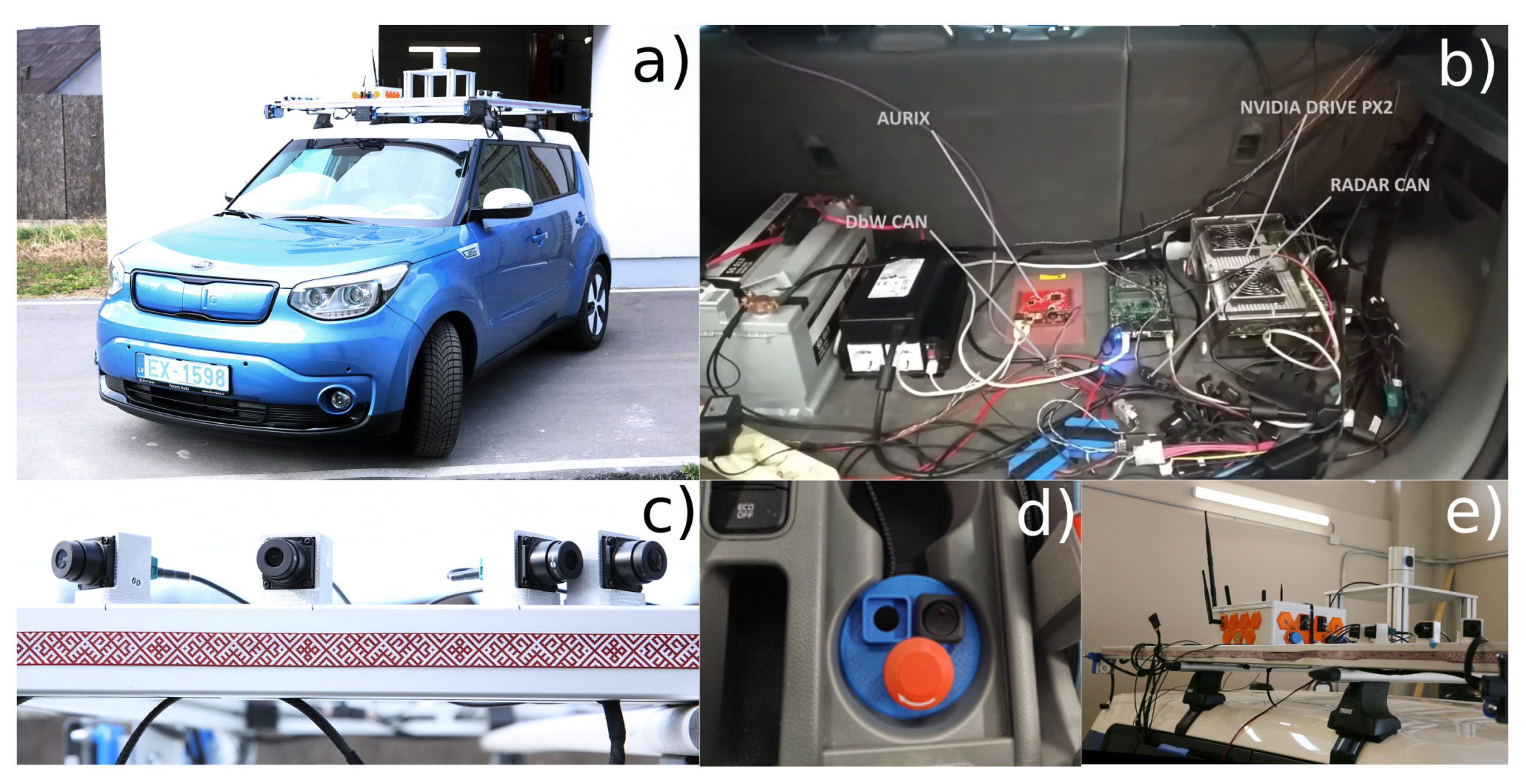
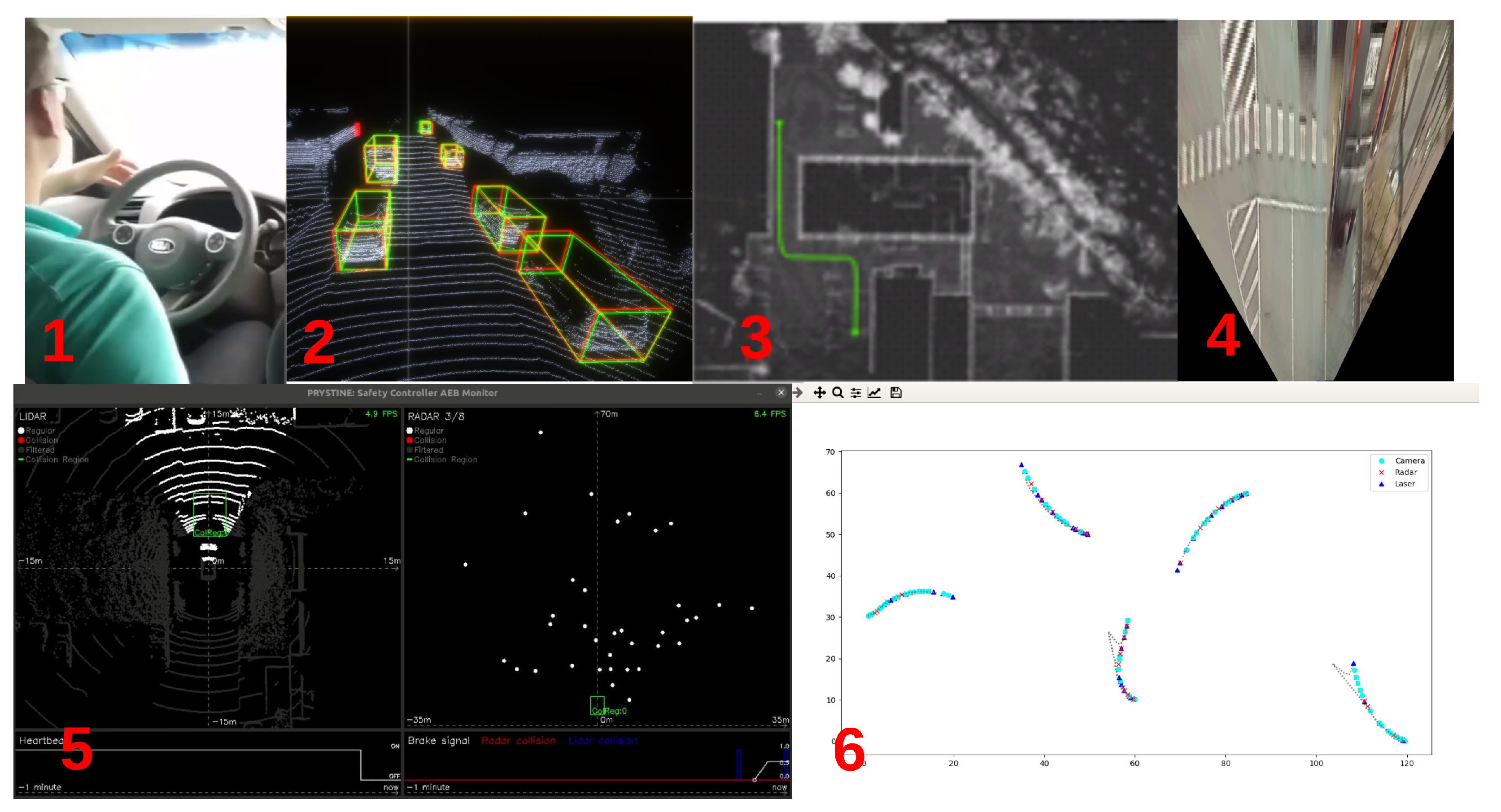
In the PRYSTINE project, the Institute of Electronics and Computer Science (EDI) developed novel data fusion and processing approaches, which were implemented on its EDI DbW car, illustrated in
Figure 5. The overall functional architecture, described in [
31], realizes the standard perception, planning, decision-making and control pipeline. Here, we present the implementation and the first test results of this architecture in multiple path execution scenarios where the vehicle deploys emergency braking if there is a risk of an impact and continues its route after having stopped if the object is removed from the road.
4.1. Safety Controller
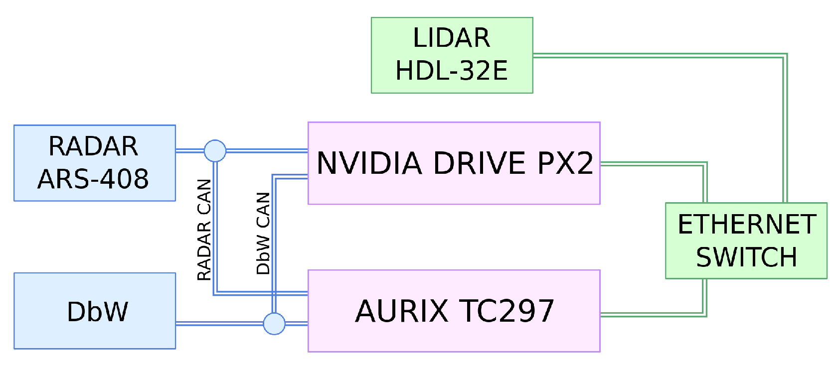
During the PRYSTINE project, this idea has been put to the test in the implemented prototype. The high-level perception system was based on the NVIDIA Drive PX2 platform, while Infineon’s Aurix Lockstep processor carries out the functionality of the safety controller. Even though NVIDIA Drive PX2 supervises the system and has its own onboard safety features, the Aurix controller has been used to monitor the state of the RADAR and LIDAR sensors and perform obstacle detection and crash prevention, i.e., perform ADAS.
A simplified controller system architecture is shown in
Figure 6, which gives a general overview of the interactions between the safety and the high-performance controllers and sensors. To respond to the obstacles detected by the RADAR, Aurix uses Continental ARS408-21 RADAR’s built-in functionality. This functionality enables a setup of certain collision regions, where if an object is detected, it generates an emergency message sent over the CAN bus.
The other functionality of the safety controller is to process the data from the LIDAR sensor. In this particular case, the LIDAR perceives the environment by spinning 360 horizontally and firing 32 lasers simultaneously with a vertical angle ranging from −30.67 to 10.67. Each point from each laser is expressed in spherical coordinate system, where d is measured distance to an object, v and h are vertical and horizontal angles, respectively. Points are further broadcasted over the Ethernet using the UDP protocol, permitting multiple receivers. Safety controller first filters out received points outside of the region of interest by horizontal angle to reduce computational cost.
Furthermore, in order for collision detection to ignore small objects, we filter them out. Computing the size of an object from one viewpoint is challenging, as only part of an object can be seen. We perform filtering by first dividing space into 25 × 25 × 25 regions or boxes and grouping points into each box. For every box, we compute variance along the axis and diagonals to measure the spread of points. If the points are spread out in any direction, we consider the object too large.
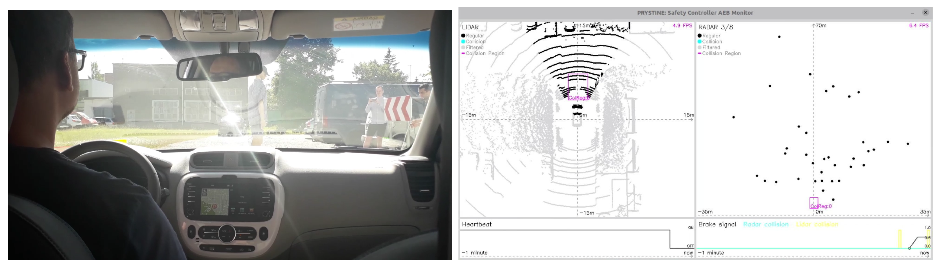
Finally, for obstacle detection, we compute the intersection of each leftover point with an axis-aligned collision region defined by two points
and
in a vehicle-coordinate system. The collision region could be calculated once or recalculated on the fly depending on the environment circumstances or using other metrics such as speed. An example of testing the approach in pedestrian crossing use-case is shown in
Figure 7.
4.2. High-Performance Controller
The implementation of the high-performance controller utilizes a combination of system architecture frameworks tailored for deploying software architectures onto embedded Linux-based platforms—COMPAGE (
https://gitlab.com/rihards.novickis/compage, access date: 1 October 2021) for component-based software management and ICOM (
https://gitlab.com/rihards.novickis/icom, access date: 1 October 2021) for component communication. We have leveraged these frameworks to construct a distributed system with AI-based algorithms capable of identifying faulty sensors by analysing their data, e.g., LIDAR, RADAR, cameras. EDI DbW perception system components and their visualization are described and shown in
Figure 8.
One of the most crucial aspects while performing
Dynamic Driving Task (DDT) is the elimination of the risks of collision. However, a complete risk elimination is a practically unattainable task. Safety can be improved to acceptable levels by introducing ADAS, which directly or indirectly can affect a vehicle’s manoeuvrability and can execute an emergency scenario such as
Automatic Emergency Braking (AEB). Such systems often act in parallel with DDT and interrupt the driver in case of a potential emergency. While ADAS are commonly known for driver assistance, it is possible to utilize them for monitoring and input generation to a higher level perception system. The goal of such an approach relies on the principle of total reliability in parallel systems, which states that a parallel system fails only if all its parts fail [
32]. Therefore, it is required to have at least one system in parallel with a higher reliability index.
The EDI perception system addresses this principle at two levels—architectural and sensor. At the architectural level, the fail-safety is ensured by the safety controller while the redundancy at a sensor level is achieved by utilising multiple software components.
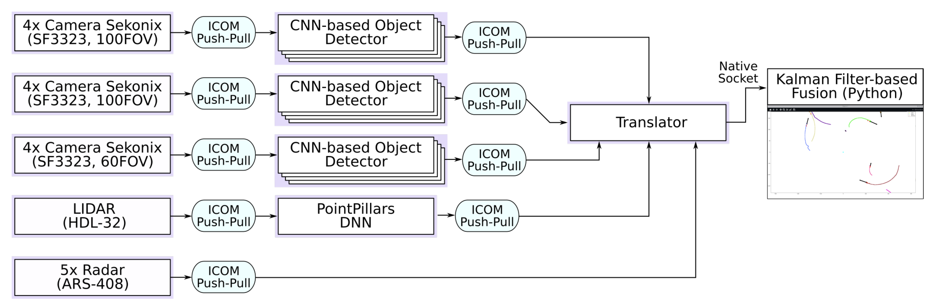
Figure 9 illustrates the object detection and mapping pipeline part of the perception system. Each rectangle represents a
compage-instantiated software component, i.e., thread, while
icom ensures inter-component communication using the push-pull paradigm. There is a single camera acquisition thread for every four cameras due to the internal structure of the NVIDIA PX2 hardware, where a single hardware controller manages four-camera ports. The software components can be distributed across different processing systems, e.g., single PX2 platform incorporates two Hexa-core SoCs connected through a high-speed Ethernet switch; nevertheless, even a single SoC is capable of managing the FUSION pipeline with an average control loop length not exceeding 100 ms. This is mostly possible due to the zero-copy and synchronisation features enabled by the
icom framework. The Python fusion GUI has been deployed on a PC for demonstration purposes.
The Fusion algorithm’s role is to get the best estimation of the states (e.g., position coordinates or velocity) of surroundings by giving more weight to the sensor measurement, which has less uncertainty. The algorithm ensures the safe operation of the vehicle in case of a dropped sensor measurement (sensor loses connection), as the same object is tracked by other sensors, while the best estimation is assigned to the object due to the least uncertainty criterion. If the measurements are persistent within a certain range, i.e., an object is detected, the object can be assigned a trajectory to be followed and predicted in the future. The Motion model is utilizing mathematical equations describing the physical behaviour of objects for predicting future states of the systems, based on the measurement history and currently estimated states. Dead reckoning is used to predict the future states based on a given state (previous/current). Motion model can perform the Dead reckoning, which is beneficial for hidden objects due to any barrier existence in the sensor’s field of view. Dead reckoning is a preliminary step for motion prediction (and accordingly Behavioural planning) of objects around the car, especially if they are not visible for some time period.
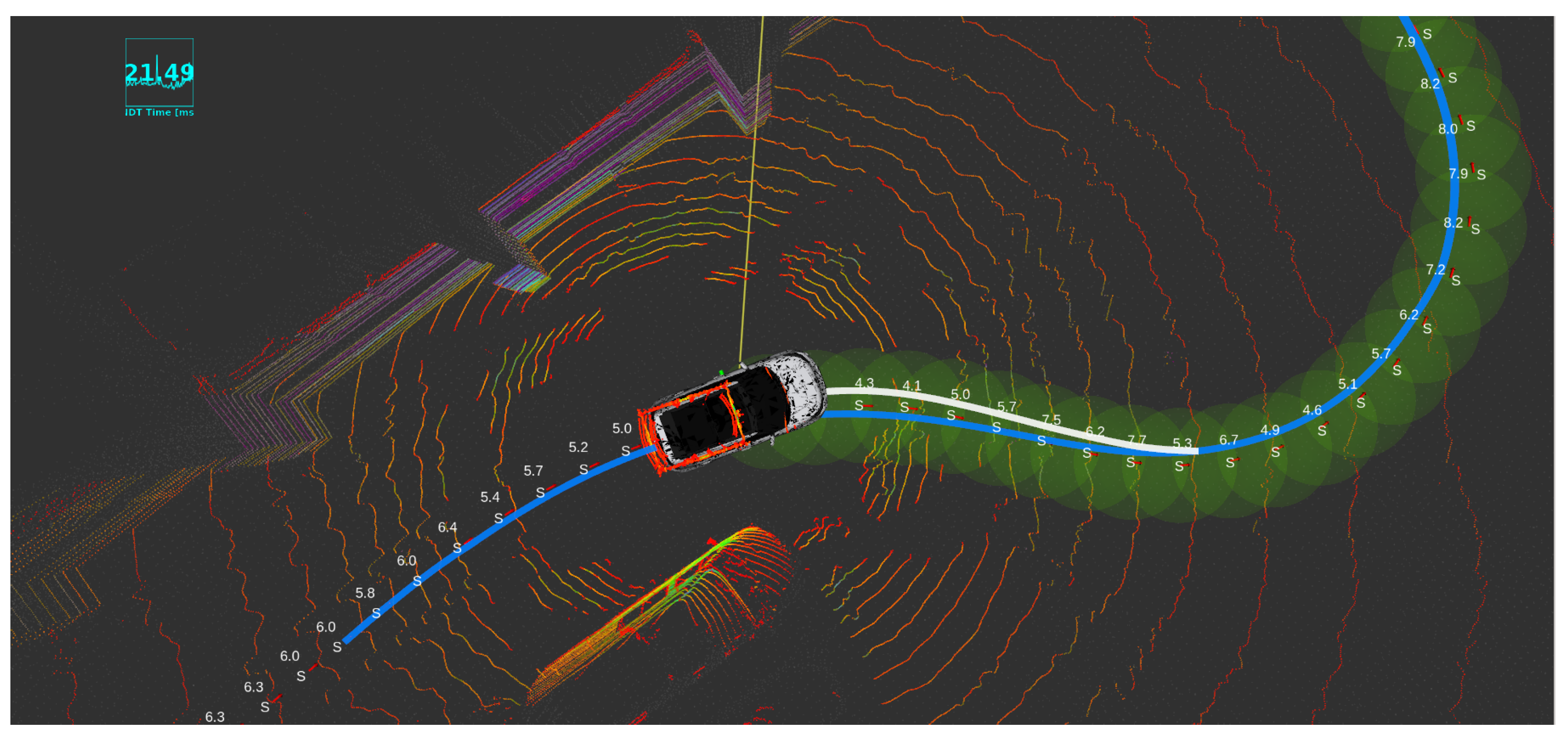
Furthermore, the egomotion planning of the car is implemented and tested with Autoware package built-in modules (Shown in
Figure 10). To meet this requirement, different approaches were tested, and as a result, Model Predictive Controller (MPC) was the best candidate to be used for path planning. Another approach is based on a “pure pursuit principle”, which takes into account only the trajectory to be pursued and generates control using a simple PID controller.
5. Passenger Vehicle Demonstrator for Low Speed Autonomy (PVLSA)
While fully autonomous traffic is still far away in the future, most OEMs are striving for mass deployment of SAE level-2 vehicles [
9] with a limited proportion of conditional and highly automated driving (i.e., SAE level-3 and level-4 [
9]) operations expected in the next decade [
34]. In this respect, one of the first applications or use-cases of automated driving, starting from automated vehicles with SAE level-2 autonomy, is the automated parking and retrieval operations [
35]. The main reasons for the attractiveness of this use case are as follows:
During a typical parking manoeuvre, vehicle dynamics are mostly negligible, and motion is predominantly kinematic, simplifying control and planning tasks.
The dynamic environment does not typically involve rapid changes (compared to on-road driving), and in most cases, can even be considered as quasi-static. Please note that this does not exclude edge use-cases, possibly involving highly-dynamic scenarios, which are, however, outside the scope of this study.
Vehicle parking and retrieval are usually considered a burden for many vehicle owners and thus automated valet solutions are likely to have more interest and user acceptance than general automated driving operations.
Motivated by these, a dedicated demonstrator named “Passenger Vehicle for Low-Speed Autonomy” (PVLSA) was developed in the scope of the Prystine project to implement parking use-cases. While it is not a new application area, the implementation involved the development of dedicated environmental perception algorithms as well as the path planning for parking. The perception algorithms utilize AI algorithms with superfluous combinations of RADAR, LIDAR and camera. The focus of the demonstrator was, however, parking use cases in cluttered environments, where different path planning algorithms were implemented and compared using a set of KPIs.
The baseline for PVLSA demonstrator is the existing SAE level-2 and level-3 vehicles with parking assistance systems. The best SotA for this is the “Autopark” and ”Smart Summon“ systems from Tesla, which are designed respectively for parallel parking assistance and automated retrieval of the vehicle in parking lots. These, however, are based on camera perception alone and are reportedly not working up to the customer expectations. The PVLSA demonstrator, on the other hand, aimed to demonstrate similar implementations of automated parking utilizing sensor fusion approaches (i.e., perception using cameras, LIDAR and RADAR) to improve the robustness of the decision-making process. As an environment of interest, a typical parking lot scenario was assumed for this purpose, and the set goal was to park in predefined spots provided as user input, utilizing backward and forward parking manoeuvres. The main contribution of the PVLSA demonstrator in this respect is the development and benchmarking of a high-level trajectory planner based on RRT (rapidly exploring random tree) family of search-based algorithms [
36] for efficient navigation and automated parking in cluttered environments.
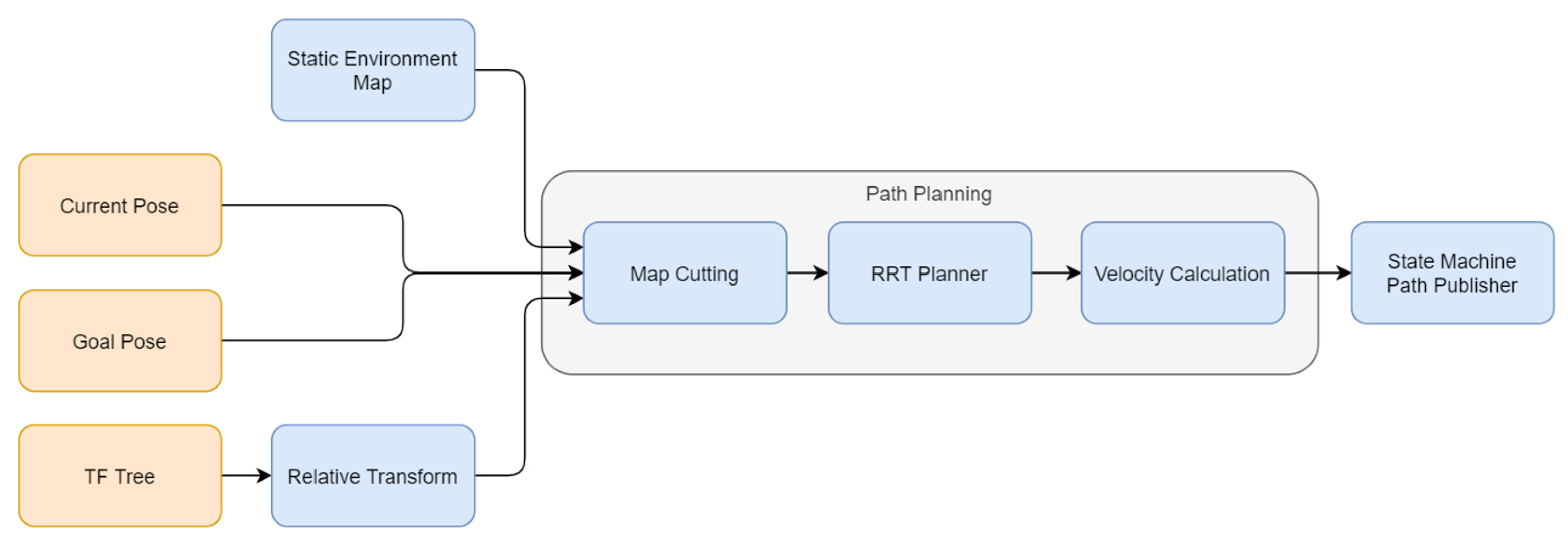
The RRT-based trajectory planner block requires an environment map as well as start and goal positions, based on which path planning is performed. The RRT-based planner calculates a path or generates an error message, which indicates whether a goal state collision exists or if no path is found within the specified time. For the tracking controller, a way-point list with a pose and a set velocity is required. As the RRT-based planner does not provide velocities (see description of Rapidly-exploring random tree on Wikipedia:
https://en.wikipedia.org/wiki/Rapidly-exploring_random_tree, access date: 2 June 2021), the path planning module is extended with a block for velocity calculation. The architecture of the path planning pipeline is illustrated in
Figure 11.
5.1. Experimental Setup and Testing Methodology
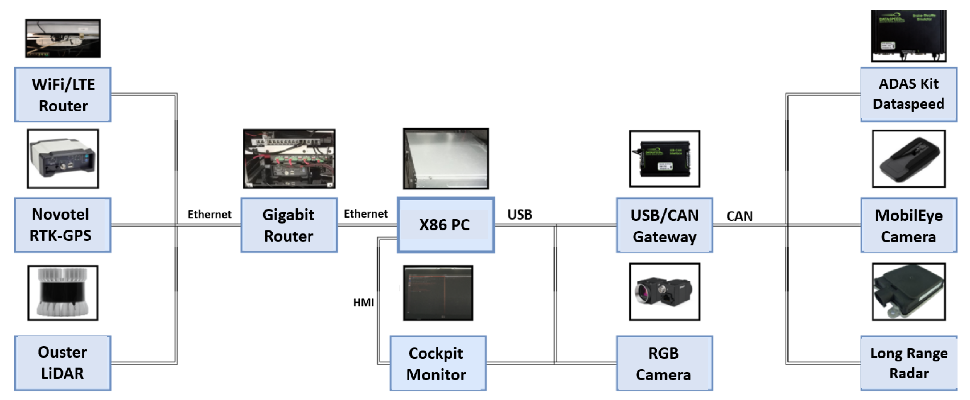
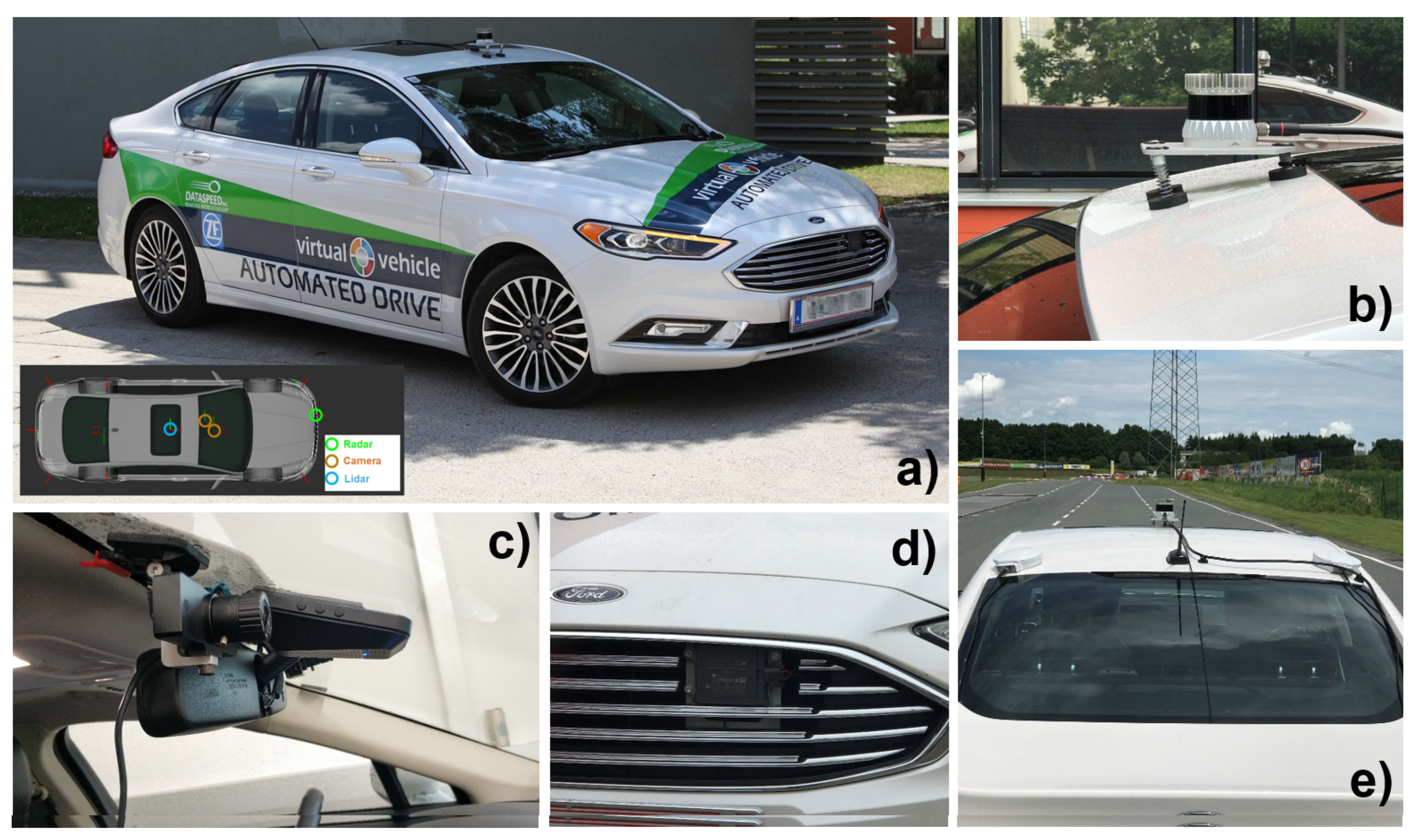
In order to validate the developed RRT-based trajectory planning algorithms, an automated driving demonstrator vehicle seen in
Figure 12 was utilized. The vehicle is a stock Ford Fusion MY2018 test vehicle that is equipped with several additional sensors and computational hardware as well as custom software components. The basis hardware is the Dataspeed ADASKit [
37], which enables the basic steering, braking, and acceleration controls of the vehicle along with access to all onboard sensors. Additionally, the vehicle has a dual-antenna Novatel Propak6 RTK-GPS system, a Continental ARS408 long-range RADAR, a Mobileye 630 intelligent camera, a Blackfly S GIGE RGB camera, and an Ouster OS1-64 LIDAR sensor. The mounting positions of the perception sensors are indicated in
Figure 12. For the implementation, the Autoware AI software stack [
38] based on the ROS-1 middleware [
39] was utilised. The components and their respective wiring scheme are shown in
Figure 13.
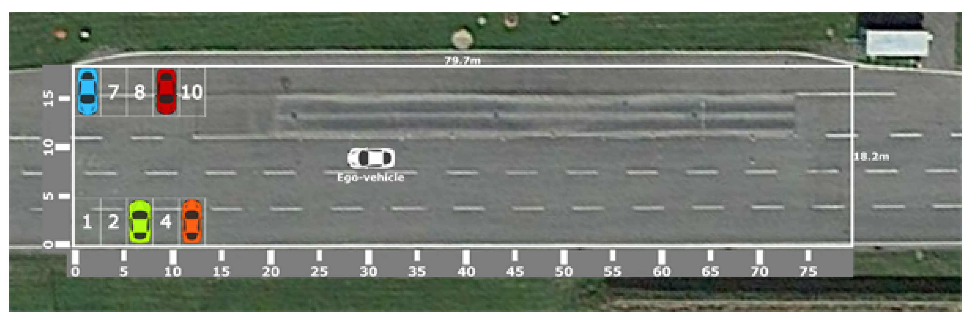
The validation of the RRT-based trajectory planning algorithms for parking was made using a set of scenario-based real-life tests. The test scenario is shown in
Figure 14 as a typical parking situation in a static environment setting. The static environment in this context contains 10 parking spots, each one with dimensions
m and a distance of 8.2 m across the two rows.
The KPIs were mainly chosen to analyze the trade-off between quality of results and computation time. In this respect, the KPIs are selected and grouped mainly to measure path quality and computation time. The selected Path-Quality KPIs are success rate, length of the planned path (in meters) and length of the planned path in reverse (in meters). The selected computation-time KPIs are execution time for the path planning step (in seconds), the number of nodes in the tree, and the number of collision checks performed.
5.2. Test Results
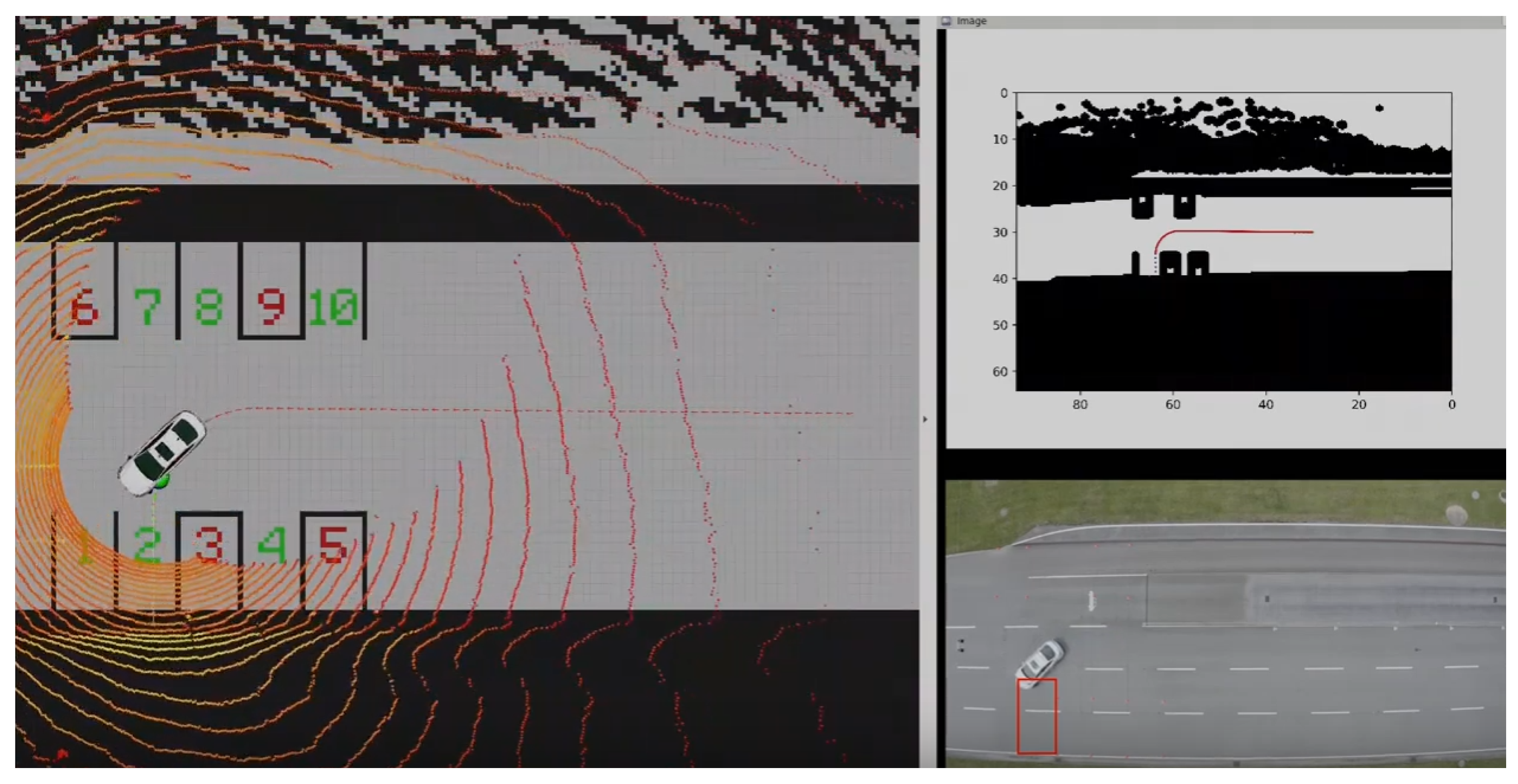
A representative real-life parking test results for a selected set of different RRT algorithms for parking at the spot-1 are summarised in
Table 2 and a snapshot of the test video is shown in
Figure 15. Since the RRT algorithm is probabilistic, these results are reported with their mean and standard deviation value across 50 random runs of the algorithm. We restricted the maximum execution time to 30 s and report the mean and standard deviation calculated across the successful runs. Finally, we also report the success rate for each algorithm, which indicates the number of times of finding a feasible path (i.e., conforming to the restrictions) during the 50 random runs.
5.3. Conclusions
The PVLSA demonstrator was utilised to develop a set of perception, planning and control algorithms to realise an SAE Level 3+ automated parking solution. As part of this, we described in this paper a specific implementation of RRT-based algorithms for path planning purposes in low-speed autonomy use-cases. Scenario-based real-life validation of the algorithms was performed in a use case involving a static environment.
The main contribution of the PVLSA demonstrator is a benchmark of the respective algorithms in real-life validation tests. Test results indicate high success rates for the RRV and RRTx methods at very low computational overheads, which are promising for utilisation in further analysis. The utilised use-case scenarios were selected in the interest of achieving a simple basis of comparison for the selected algorithms. On the other hand, these scenarios were overly simplistic to assess their performance in a typical usage cycle of the provided solution.
It remains to extend the evaluation in more challenging scenarios and further develop the existing solution, potentially, as a part of commercial exploitation. There are many potential implementation areas of the developed solution including:
Self parking solutions,
Automated personal mobility services (i.e., Robo-Taxi),
Autonomous delivery of goods (parcel, cargo, food, etc.),
Road cleaning robots,
which shall form future areas for potential exploitation.
6. Trust Model—Enhanced Fusion in Secure Computing Platform
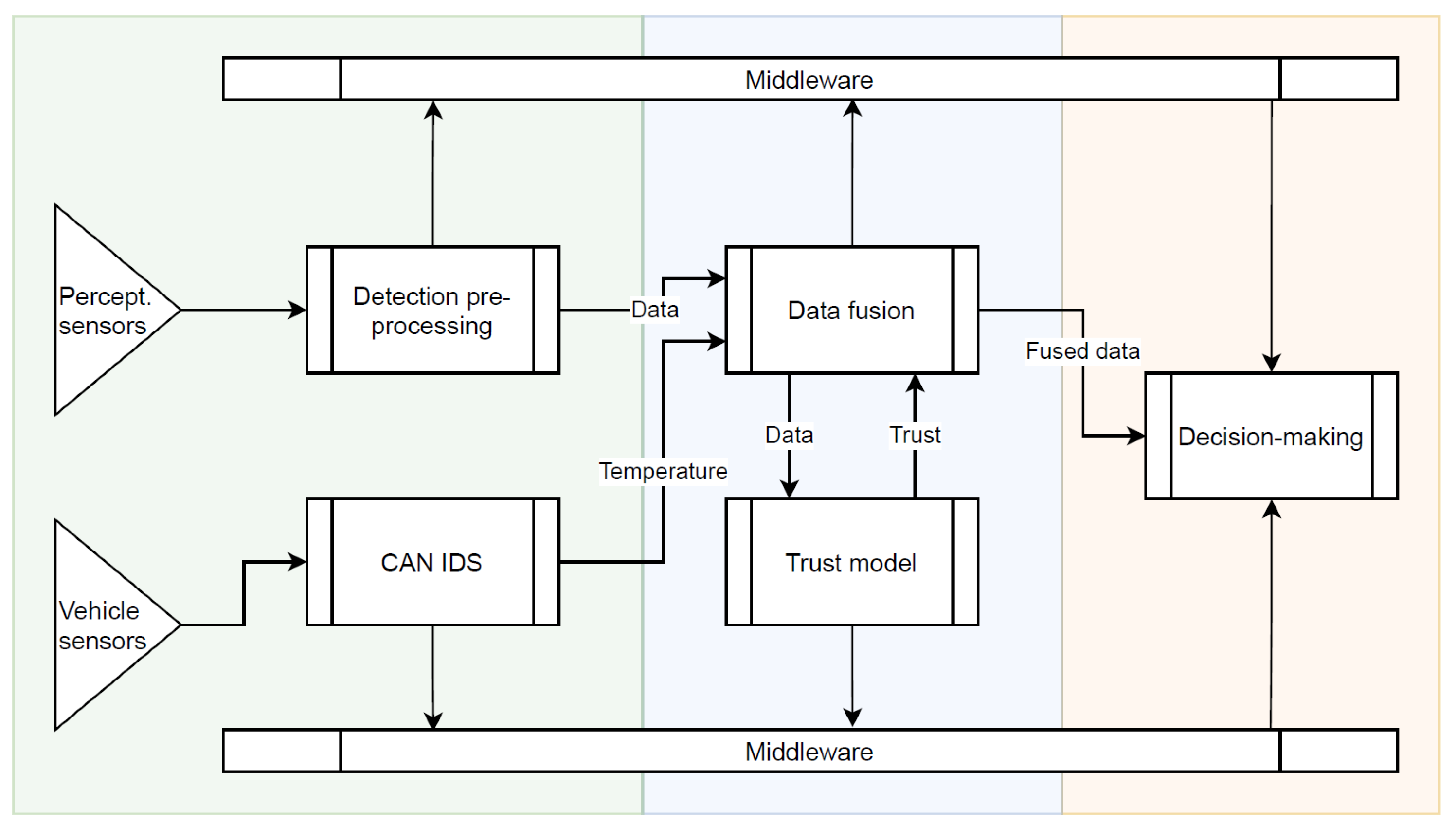
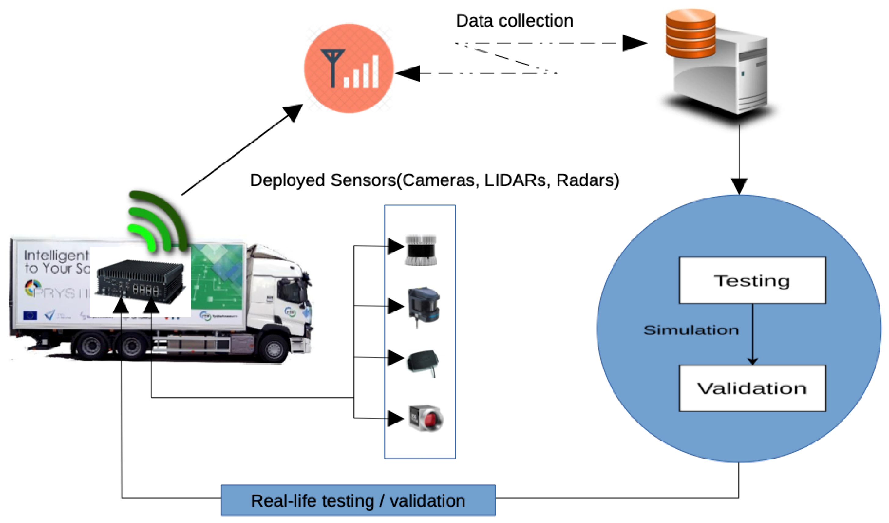
Demo 2.3 (Perception system with built-in security, trust and operations monitoring) showcases a fully integrated security, trust and real-time operation monitoring for realising secure and fail-operational perception system for autonomous heavy-duty driving. Security and reliability of sensor data and SW/HW components of the central computing device are key for accurate perception of the environment. The demo integrates a trust model, intrusion detection system for vehicle CAN bus, and a middleware that provides built-in security and real-time operation monitoring for enabling fail-operational features. The overall system architecture as well as the testing and validation process of the Demo 2.3 are shown in
Figure 16 and
Figure 17, respectively.
The trust model of the demonstrator is designed to be able to evaluate the trustworthiness of vehicle perceptual sensor data while taking into account aspects of the data that can be affected by external or internal factors and consequently have their reliability altered. The covered factors are categorised as environment, operation, security, and design. The first considers how operating in different weather, temperature, and lighting conditions affects the object detection capabilities of the sensors; operation, on the other hand, tracks the behaviour of the sensors while they are used, monitoring wear and continuous reliability of consecutive detections; security tries to include the threats detected by security-oriented components into the trust evaluation; and the final category covers sensor design -related details, such as limits on what the sensor is able to see or how many objects it can track.
The current trust model implementation receives RADAR detection data from the data fusion module. Their trustworthiness is evaluated with regard to the reliability of the RADARs, namely the Brigade BackSense-9000 and Continental SRR-201-21, under varying circumstances. The results are finally sent back to data fusion, where they can be used to adjust the effect untrustworthy sources have on the vehicle’s perception. The utilisation of produced trust values in this filtration is an ongoing effort, with some initial approaches planned, e.g., a step function or linear correlation. This process enables the estimation and tracking of the dependability of the RADARs as data sources.
Challenges were met both on theoretical and practical levels. A method had to be found to calculate trust when multiple parameters are individually assessed. Additionally, the numerical impact of each parameter had to be determined for the model to produce as accurate results as possible. Finally, some parameters would inherently require input from other components or equipment in order to be implementable. To resolve the first challenge, the evidence theory by Dempster and Shafer [
40] was chosen as a framework for combining trust and distrust values. It is computationally simple and thus allows us to achieve good performance while keeping the processing delays minimal. The second challenge is an iterative one, as there are no objectively correct values to assign to many of the parameters, i.e., those for which they can not be derived directly from the data but circumstantial evidence has to be applied. They then require continuous optimisation through testing, until the evaluation appears to reflect appropriate changes in data trustworthiness.
Unfortunately, trust evaluation related to security, weather, component wear, as well as parameters requiring unique object identification has been delayed or been made impossible to attain due to a lack of equipment or delays in the development of other components. Due to delays encountered in our data fusion development, persistent object identifiers have been unavailable, and as such it has thus far been impossible to evaluate the trustworthiness of detections of a given object over time. Additionally, the evaluation of the impacts of weather and component wear has not been possible because suitable equipment to enable such tasks has not been available.
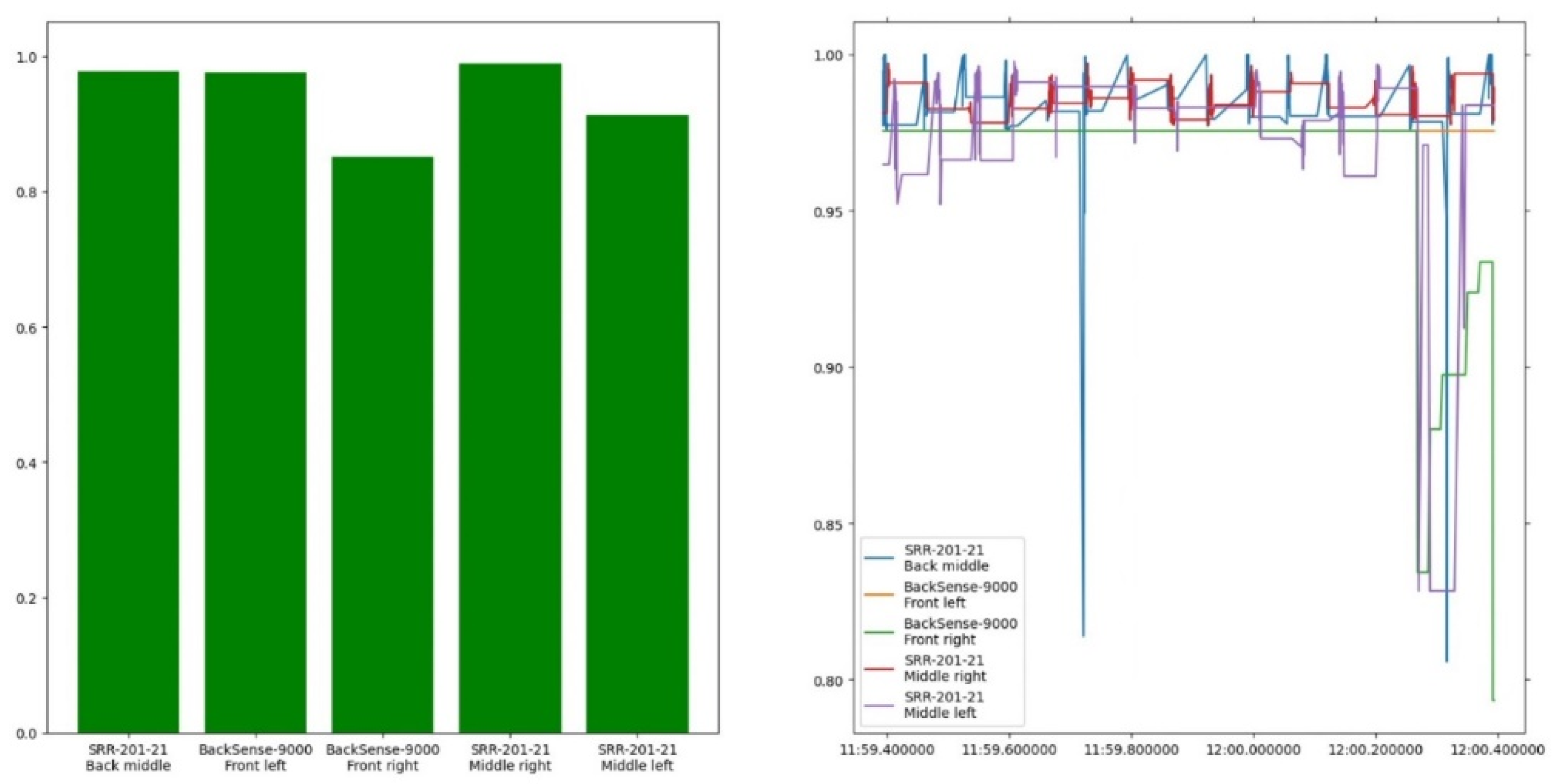
Figure 18 shows a screen capture of the visualisation provided by the trust model. The left half displays a bar chart containing the instantaneous trust in the active sensors. The right-hand graph displays a history of the most recent trust evaluations over the past second (note the vertical scale). Additionally,
Table 3 contains the results of the implementation’s benchmark test. The average runtime column shows the runtime of the major methods used during the trust model’s operation. The evaluate method is the one responsible for trust evaluation and is called from handle_phase1 if the received data are suitable for evaluation, i.e., are not vehicle CAN data containing environmental information. The frequency column corresponds to the respective frequencies, rounded down to the nearest hundred Hertz, representing the maximum evaluation rate.
Controller Area Network (CAN bus) is a widely adopted technology for in-vehicle communication with desirable properties such as robustness, flexibility, speed, and relatively low cost. As there are no inbuilt security mechanisms for vehicular CAN buses, we developed and tested an Intrusion Detection System (IDS) for a CAN bus. Without a security mechanism, such as an IDS, no claims can be made on the confidentiality, integrity, authenticity, and freshness of messages in the presence of a malicious attacker. There is often the need to find a balance between the sensitivity and specificity of an IDS, and total elimination of false positives is not possible. In the case of an IDS protecting the vehicular CAN bus, simply discarding suspicious traffic may compromise the normal operation of the vehicle and its safety. There are no security specialists on-site, and possibly no time for human action either. As a result, it is necessary to come up with different strategies for handling security breaches in vehicles, in particular for the vehicular CAN bus. Pulling off the network cable is not an option. Fail-safe and fail-operational capabilities may be crucial for effective and safe actions in response to alerts raised by the IDS.
The developed CAN bus IDS is integrated into the overall system as shown in
Figure 16, and its outputs are to be used in the middleware for the system-health check, which will then be displayed to the driver. In the future, the possibility for more effective actions could be investigated, such as a safe-stop (during an ongoing cyber-attack). The practical value of a vehicular CAN bus IDS can be judged by its specificity, sensitivity, hardware requirements, and latency. There are several different approaches to building a CAN bus IDS. It is a real challenge to come up with a single approach that has all the desired properties, as different approaches have different strengths. Combining several complementing approaches is one way to obtain a more complete solution, but of course, hardware requirements and latencies add up. With this understanding, we focused our efforts on a partial solution that is suitable for combining with other solutions due to its lightweight nature.
The developed CAN bus IDS operates by detecting anomalies in
k-sequences. We define the term
k-sequence as a length
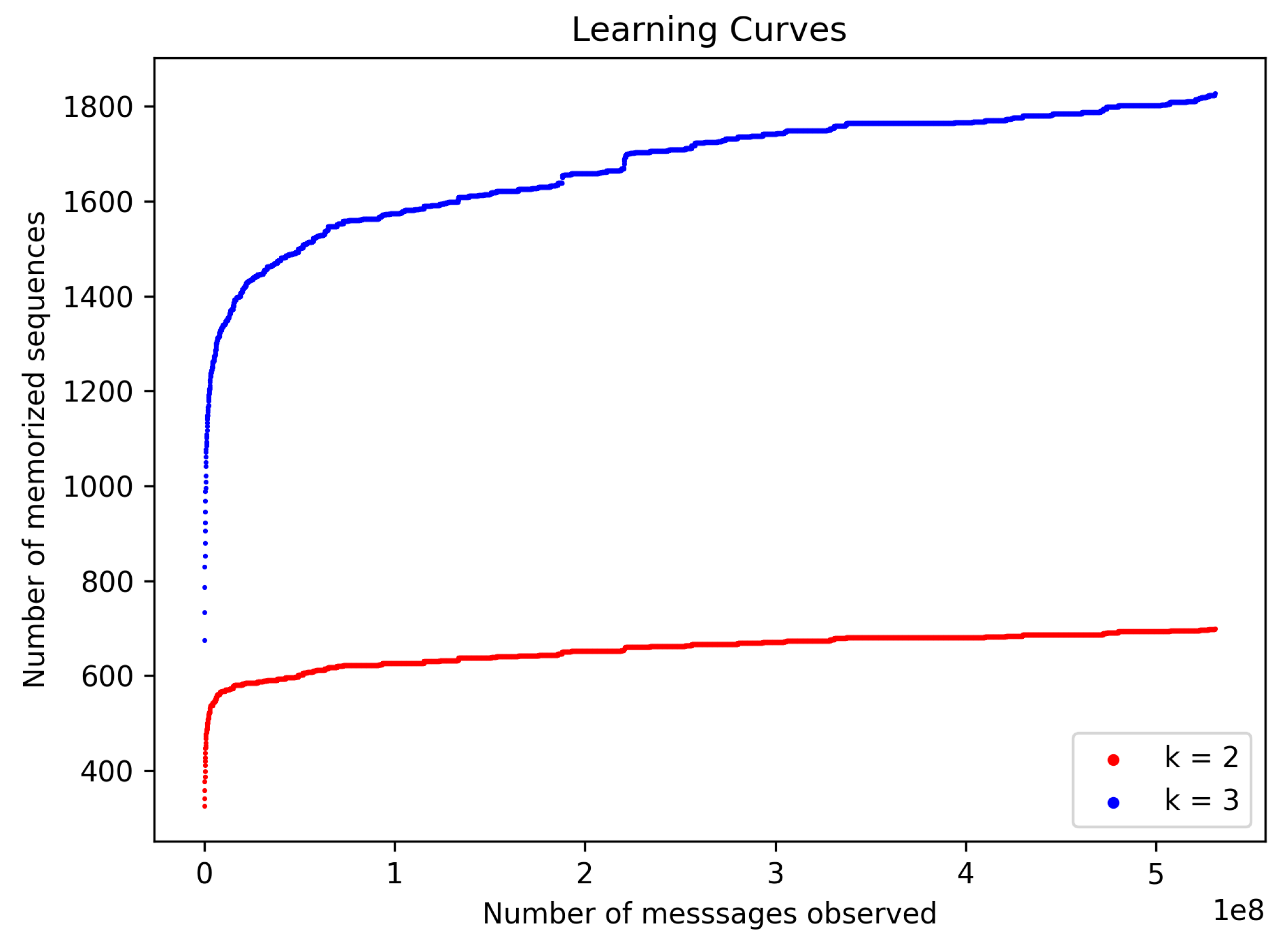
k sequence of CAN bus identifiers, and it is treated as a hyperparameter. The IDS can be described in two operational phases: training and testing phases. In both phases, IDS takes in a k-sequence as input and processes CAN bus messages one at a time. Every k-sequence encountered during the training phase is memorised and stored in an internal data structure, which serves as a whitelist. Contents of the whitelist, at the end of the training phase, correspond to the learned model. In the testing phase, each received CAN frame appears in a number of k-sequences, each of which is looked for within the trained model, and an alert is raised if not found. Behaviour in the testing phase also describes a normal mode of operation of the IDS.
Figure 19 below depicts the model as it matures with the reception of additional CAN messages during the training phase.
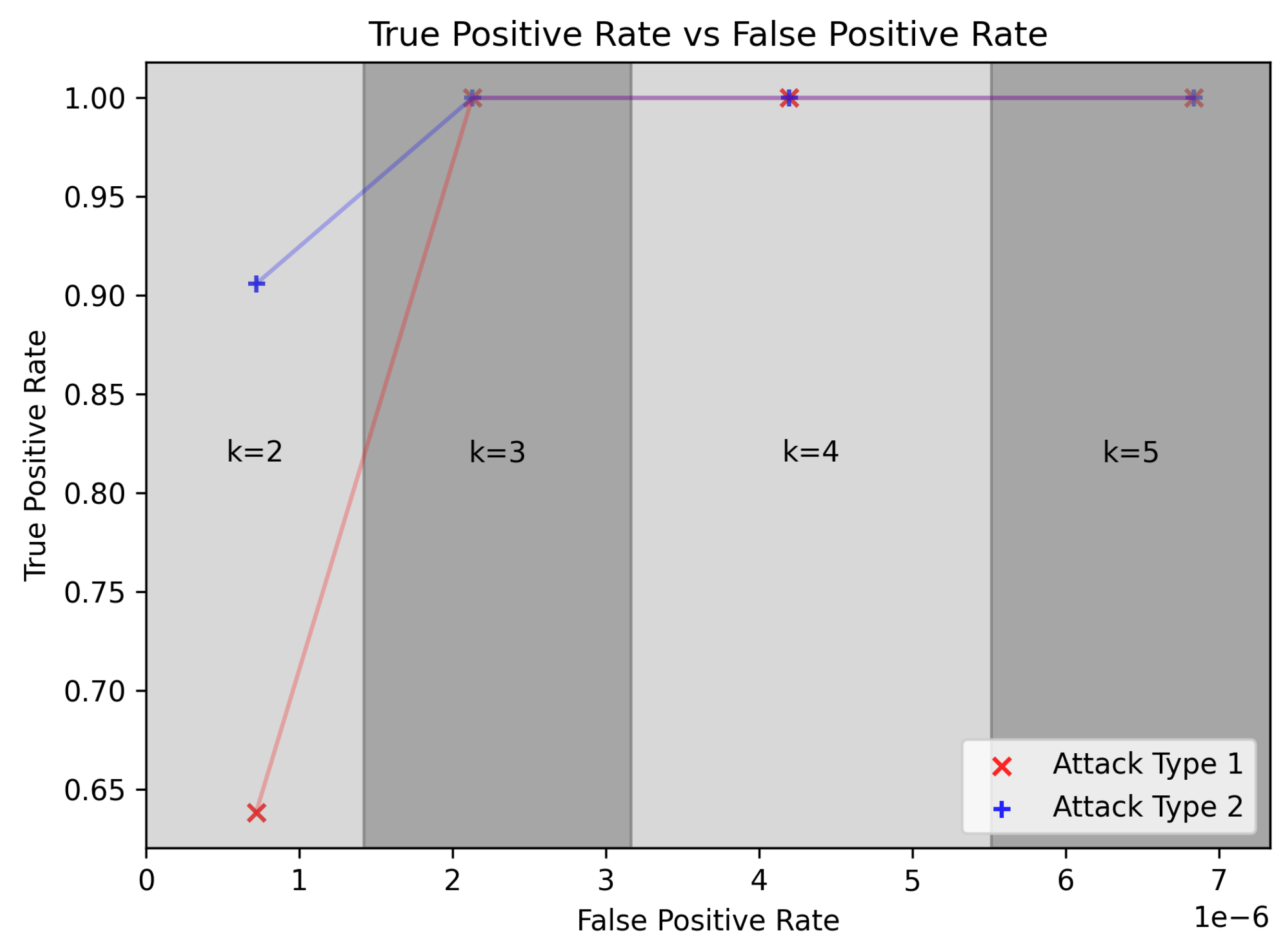
All inter-vehicle communication on the bodybuilder CAN of the TTS heavy-duty truck is observed by the CAN bus IDS. The main results of IDS are presented in
Table 4 and
Figure 20. Results are presented separately for different values of a hyper parameter
k. True positive rate is above 0.9 for
, and greater than 0.95 for
.
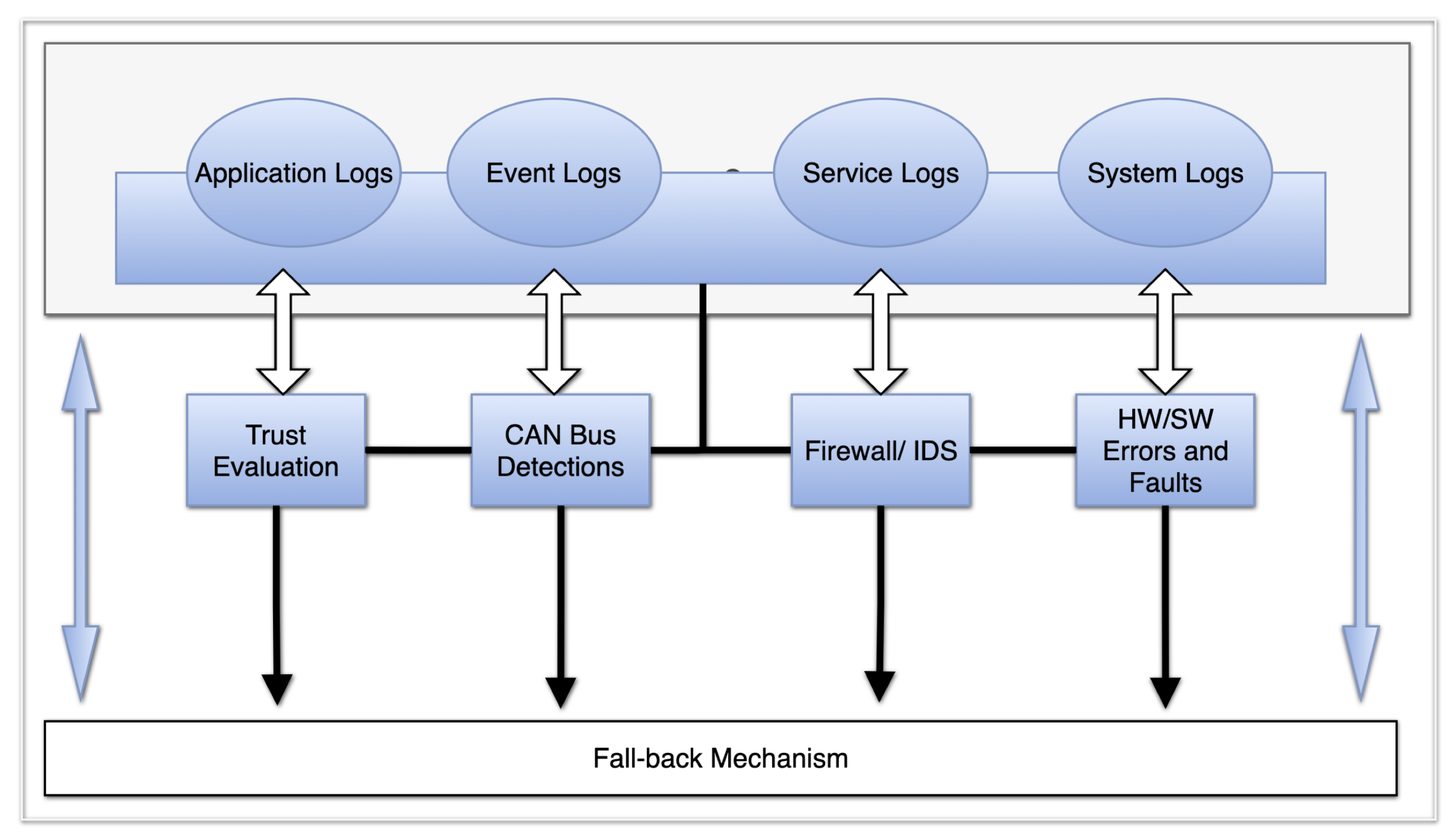
The importance of failed operations coupled with security requirements increases as one moves from the L3 to L5 level of automation. The in-vehicle built-in security infrastructure is handled by the middleware, which does not only focus on the security aspect but it is also addressing both safety and reliability. Characteristics and properties of the security solution encompass features such as monitoring, analysing, storing critical communications in a lightweight SQL, and the act of interpreting application and process response in real-time. In addition, the idea and concept of reducing on-road incidences with precision navigation has to reflect the security fail-operations and other factors such as IoT relationship to autonomous vehicles in terms of attack vectors. The general overview of the middleware in-vehicle security solution is shown in
Figure 21.
The middleware security solution for our heavy-duty truck is broken down into functional components such as the log-stashing component, analysis component, security component, and monitoring component. The first step was evaluating the OEM. The most common and popular Linux distribution designed for general use, such as Ubuntu, does not ship with specialised hardening security tools. Therefore, all needed specific security and hardening procedures were first achieved through a custom implementation. The middleware security mechanism follows a common security practice by layering security measures across each component to achieve a fail-operational security level while maintaining the properties and characteristics of each functional component. Critical applications and internal communications, including services, daemons, manually triggered processes, and specific critical events, are monitored in real time by monitoring the functional component. This allows for implementing fall-back operations in real time via alerts. The alerts and key indicator messages, as shown in the below figure, include firewall and security incidents, hardware and software faults, operation escalations, CAN bus health and security issues and critical trust evaluation parameters via real-time system activities and logs.
The security component consists of firewall implementation, process accounting, system activity audits and intrusion detection systems, which are executed in parallel with the firewall. Packet inspection is done upon entry on the main external front-facing interface, which is also monitored by IDS. Normal operational activities of each branch are logged separately to its respective log paths. Most critical activities are logged directly to system logs, which are handled by the Syslog. The auditing and accounting processes are handled in the same manner. The main purpose is the evaluation of processes and permissions against predefined rules and reporting incidents and users that triggered the rule and the according instance.
Knowing the operational status of integrated hardware components is critical for road safety perception because the driver is dependent on the generated data. Therefore, our solution needs to acknowledge the hardware system failures and corresponding software errors and faults. Hence, system health status, which includes sensors, CAN bus, trust evaluation messages, firewall/ IDS, and health status of other critical services, applications, and daemons, are used to calculate the general health status at startup and runtime. This helps the driver to determine the integrity and reliability of any component, which influences on-road decision-making in terms of the fail-over and fall-back status. To achieve this, the alerts and messages from detected critical errors and faults are reported to the middleware component that handles the resolution. The first step is sending a notification on the status of the error or process, which are labelled either basic, critical or support. Situations that can be successfully resolved are carried autonomously, while unsuccessful situations are alerted with label support. All these messages are forwarded to the Human Machine Interface (HMI) panel.
7. Summary and Discussion
The PRYSTINE project’s goals were to enhance the existing architectures, address the complexity of the E/E systems and implement automated driving functions for future automated mobility. At the same time, these solutions must ensure the highest automotive safety standards (ISO26262 up to ASIL-D). In this article, we address the challenge of reliable perception and demonstrate potential avenues for future research. This challenge requires a multi-disciplinary approach, where the underlying hardware enables fail-operationality, algorithms ensure reliable perception while meeting real-time performance criteria, and software anticipates and monitors for failures. Furthermore, an actual deployment and acceptance of these life-saving technologies (In 2019, road incidents were the 12th leading cause of death worldwide and 6th leading cause of disability-adjusted life years [
41]) involve budgetary limitations, as opposed, for example, to the aerospace domain.
The presence of common cause failures, for instance, those originating from systematic hardware and software faults, are critical problems to be solved to avoid catastrophic events. The currently available MPUs on the market do not support hard real-time and automotive quality interfaces and the highest grade of availability, SEMPER proof security and functional safety up to ASIL-D. The fail-operational systems in passenger vehicles require a highly available “last man standing” solution that can not be achieved with incremental upgrades, such as Automotive Electronics Council’s AEC-Q100 certification. The exploration of Simplex, 1oo2d and hybrid fail-operational architectures suggests a need for the automotive-grade processor to include substantial extensions, such as comparison hardware and possibly complete secondary cores. Nevertheless, this would provide an opportunity for silicon vendors to offload such hardware design complexities from the system developers.
On the perception side, modern AI-based algorithms continue to surpass conventional approaches in a variety of use cases. Nonetheless, the black box (or grey box) nature of the DNNs puts additional responsibility on the technology provider and imposes a significant requirement for ensuring and displaying technological reliability for the public. We adopt an approach rooted in multi-modal sensing and fusion. We anticipate long-term solutions not only fusing the outputs of different AI-based algorithms, as they provide SoA performance, but also mixing them with more conventional yet simpler algorithms for ensuring fail-safety.
The colossal financing of the autonomous driving domain did not meet the set expectations as further no-income R&D investments are projected until the end of the decade. Nonetheless, a key to more sustainable progress towards the highest levels of autonomy is a gradual adoption of the already available technologies, as already accomplished with ADAS. The passenger vehicle demonstrator for low-speed autonomy addresses this challenge and shows that such applications as self-parking and autonomous delivery of goods are feasible with the current maturity of the sensors and computing paradigms.
Another encouraging research vector is ensuring the security and reliability of sensor data and SW/HW components. In this respect, we have devised a trust model for enhancing fusion that provides the operational status of the integrated components. Furthermore, the eventual acceptance of autonomous vehicles requires this information to be conveniently accessible in real-time via HMI.
In the presence of the ever-increasing connectivity inside and outside modern vehicles and the large amounts of sensor data, the complexity of E/E systems and their software functionality are growing exponentially. The previously set goal of autonomous driving has been detained for another decade. Notably, the fail-operationality constraint significantly affects the development of embedded intelligence and perception systems at different abstraction levels.
In this article, we have presented the PRYSTINE project’s developments and experimental validation results for embedded intelligence and fail-operational perception at hardware, software and system levels. The solution to the autonomous driving challenge is complex. While the support for fail-operationality must encapsulate the computing hardware design level, it also requires trust-aware perception, which combines multi-modal data in real-time. Furthermore, aside from mechanisms to improve the reliability of autonomous vehicles, we have presented a demonstrator for low-speed autonomy, which is not only validated in real-life tests but already suggests the applicability of the technology by some mainstream use cases.


 ,
, 


