Article

Tailored Magnetic Linear Birefringence in Wedge-Shaped Co Nanocluster Assemblies

by
Miguel A. Arranz
1,*,
Elena H. Sánchez
2,
Víctor Ruiz-Díez
3,
José L. Sánchez-Rojas
3 and
José M. Colino
2
1
Facultad de Ciencias y Tenologías Químicas, Universidad de Castilla-La Mancha, Av/ Camilo José Cela 10, 13071 Ciudad Real, Spain
2
Instituto de Nanociencia, Nanotecnología y Materiales Moleculares, Universidad de Castilla-La Mancha, Campus de la Fábrica de Armas, 45071 Toledo, Spain
3
Microsystems, Actuators and Sensors Group, Universidad de Castilla-La Mancha, 13071 Ciudad Real, Spain
*
Author to whom correspondence should be addressed.
Appl. Sci. 2022, 12(1), 100; https://doi.org/10.3390/app12010100
Submission received: 17 November 2021 / Revised: 10 December 2021 / Accepted: 19 December 2021 / Published: 23 December 2021
(This article belongs to the Section Optics and Lasers)

Abstract

:
The purpose of this paper is to present an experimental method to induce strong magnetic linear birefringence in two-dimensional assemblies of Co nanoclusters grown on glass plates. Additionally, we have also correlated the magnitude and characteristics of that nonlinear magneto-optical effect with the thickness and profile of those disordered nanostructures. For those aims, we have grown Co nanocluster assemblies on amorphous substrates, by means of pulsed laser ablation in off-axis geometry. This approach enabled us to obtain magnetic media with an intended and pronounced thickness profile, i.e., wedge-shaped assembly, to investigate the orientation and behavior of surface magnetization regarding both the thickness gradient direction and in-plane magnetic field. That study was accomplished by measuring the magneto-optical effects in reflection and transmission configurations, unveiling an out-of-plane magnetization whose magnitude depends closely on the thickness gradient direction. That component, arising from a graded magnetic anisotropy along the wedged nanostructure, adds a reversal mechanism to the surface magnetization, thus being responsible for the magnetic linear birefringence in our ultrathin Co assemblies.

1. Introduction

Since its discovery in calcite crystals, birefringence is a very well known effect and largely studied in optical physics. In anisotropic crystalline structures, the transmitted light propagates with two different refractive indexes, as its polarization plane is perpendicular or parallel to the optical axis of the birefringent material. For the case of uniaxial crystals, those are the ordinary and extraordinary transmitted rays, respectively. This effect has countless applications in optical devices, e.g., polarization rotators, waveplates, light modulators, or filters. For isotropic or disordered media, the necessary existence of an anisotropy axis to yield birefringence is to be induced externally somehow, e.g., stress or form birefringence in polymeric tapes. More recently, the use of pulsed lasers to irradiate different substrates has shown to be a powerful tool to obtain high-resolution bidimensional nanostructures with a defined-form anisotropy [1,2]. These laser-induced periodic surface structures (LIPSS) consist of a two-dimensional (2D) ripple array, where the transmitted light travels with two different velocities as its polarization plane is parallel or perpendicular to the ripple direction. Such approach to induce form birefringence has been extended to polymeric substrates [3], showing a retardation factor comparable or higher than LIPSS in glass systems [4,5]. Thus, LIPSS seem to be promising candidates for optical devices in flat optics, and are much more flexible and affordable than crystalline materials.
Magnetic linear birefringence (MLB) is a much more subtle magneto-optical effect, and notwithstanding, not less interesting both for fundamental research and potential applications in magnetic sensors [6]. In the case of magnetized media with some kind of magnetic anisotropy, the magnetization reversal is accomplished with two different mechanisms as the external magnetic field, H, is applied parallel or perpendicular to that anisotropy axis. Consequently, the electrical field, E, of the polarized light transmitting across those systems interacts differently with the magnetization vector, depending on their relative orientation. That leads the light to propagate with two different refractive indexes as E aligns parallel or perpendicular to H, i.e., magnetic linear birefringence [7]. The first experimental evidence of this nonlinear magneto-optical effect was observed by Carey et al. [8] in Co, Fe, and Ni–Fe thin films prepared by vacuum deposition in a magnetic field, H 0 . Thus, the surface magnetization, M, was partially induced to follow a preferential alignment (easy magnetic axis along H 0 direction), and show a hard magnetic perpendicular axis. Recently, other alternative methods have been tested to increase the magnitude and, above all, the accuracy of MLB in thin films, i.e., towards the ideal magnetic linear birefringence [8]. This could be the case of Co films grown on glass or silicon substrates, and nanopatterned later to obtain a defined and regular ripple nanostructure, showing easy and hard magnetic axes, parallel and perpendicular to the ripple direction, respectively [9,10]. The interesting applicability of that magneto-optical effect to flexible flat optics has been also studied in LIPSS on polymeric substrates and coated with a thin film of permalloy, showing the coexistence of form and magnetic linear birefringence [3].
For all the above, a deep insight of the relevant sources in the magnetic anisotropy is crucial to control the processes for magnetization reversal in 2D systems, where MLB is required later. During the last decades, wide research has been driven to the interplay between volume and interface contributions ruling the magnetization anisotropy in epitaxial thin films and multilayers [11,12,13,14]. In the case of ultrathin 2D magnetic systems, a dominant interface contribution can force the magnetization vector to orientate perpendicular to the film plane, overcoming the shape effect. That transition from in-plane to out-of-plane magnetization is controlled by the film thickness, t, and is reported to occur below a threshold value, t 0 , when the magnetic anisotropy energy, K e f f , is dominated by the interface contribution, K S [12,15]. The research has been extended to wedged magnetic films [16,17,18,19], where the commented spin–reorientation transition can be easily observed in a thickness range along the film size. For the same purpose, an original approach has been recently proposed in 2D magnetic systems whose magnetic anisotropy energy can be graded along the normal to the substrate plane, e.g., with a graded composition [20,21]. In these last cases, two different magnetization directions could be coexisting in the same physical system, with respective mechanisms for magnetization reversal. That would open a new strategy to design eventually birefringent media from the magnetic point of view.
We have focused our work on growing Co nanocluster assemblies with a strong thickness gradient and, therefore, a graded magnetic anisotropy along its direction. That method has been intended to induce two competing magnetization directions along the thickness gradient and, therefore, an MLB in such disordered 2D systems. We carried out an angular characterization of magneto-optical effects in these assemblies, in both reflection and transmission configurations, particularly concerned on their dependence parallel to the thickness gradient direction (TGD), i.e., thickness dependence. The resulting data show an induced uniaxial anisotropy arising from the linearly distorted surface, and a strong magnetic linear birefringence due to an emerging out-of-plane magnetization, M o u t . Unlike the in-plane magnetization, M i n , the M o u t component is resolved by measuring the Faraday effect, showing a coherent rotation mechanism for M reversal. Its origin has been discussed in terms of the magnetic coupling amongst the Co nanoclusters of the terrace edges in our 2D assemblies.

2. Materials and Methods

2.1. Preparation of Wedged 2D Assemblies of Co Nanoclusters in Off-Axis Geometry

A number of 2D assemblies of Co nanoclusters were grown by pulsed laser ablation (PLA) in high-vacuum environment (base pressure ∼ 10 7 mbar). The ND:YAG laser operated at 532 nm, with 0.35 J/pulse and a repetition rate of 10 Hz. Its beam was efficiently collimated onto the Co target (99.95% pure) to reach an energy density about 10 J/cm 2 . Grown Co nanoclusters were deposited at room temperature on glass substrates (18 × 18 mm). An XYZ-manipulator allowed us to regulate the relative position of the substrate holder to the ablated Co target. With the above laser parameters, the plume of evaporated Co particles was intercepted by the substrate holder at a z-distance, d∼5 cm, from the Co target, as shown in Figure 1. Prior to deposition, the glass substrate was glued on a 45 wedge and fixed to the holder. Thus, in this off-axis geometry, the substrate was finally orientated at an angle of 45 with respect to the normal of the Co target (z-axis); see Figure 1.
Deposition time, t d , was adjusted to 300 s to provide a measurable magneto-optical signal over the whole sample surface. Under the above growing conditions, 2D assemblies developed an intentioned thickness profile for the subsequent magneto-optical study. That wedge-shaped contour is outlined in Figure 1 (dashed red line) and characterized in the following Section 2.2 and Section 3.1. Additionally, we tried to determine the structure of cobalt clusters with X-ray diffraction on the coatings. In the Supplementary Materials we have included XRD scans of our samples in Bragg–Bentano geometry with Cu–Ka radiation. These measurements in every sample show broad halos from which we cannot provide evidence for a particular crystalline phase fcc or hcp.

2.2. Topography and Thickness Characterization

Topography characterization of the Co nanocluster assemblies and estimations of cluster mean diameter were carried out by atomic force microscopy (AFM) in semicontact mode, using high-resolution tips (spike radius ∼1 nm). AFM images were recorded with an NT-MDT microscope (Solver model) and analyzed with its corresponding software. We used the accurate vertical resolution of this technique to infer the mean cluster diameter from the surface height distribution. It is not unusual that the clusters/nanoparticles arrive at the substrate and have enough mobility to arrange themselves in a so-called cluster assembly. Many of these form planar assemblies made of clusters mostly arranged in a one-cluster-thick layer, provided the sample is sufficiently dilute.
The determination of the thickness profile over the whole deposited film was made with an optical interferometer (VEECO, WYKO NT1100). The substrate contribution was carefully substracted with an appropriate fitting within Matlab software and a later statistical average, as is described in detail in the Supplementary Material.

2.3. Surface Magnetization Characterization

The magnetization, M, of those 2D nanocluster assemblies was first characterized with an experimental setup to investigate the magneto-optical Kerr effect (MOKE) [22]. The He–Ne laser beam (633 nm, 1 mW) was focused on the center of the sample surface at an incidence angle of 45 with respect to its normal axis, and a spot diameter ∼0.1 mm. By means of a Glan–Thompson polarizer, the polarization plane of the beam was oriented parallel to the incidence plane, and perpendicular to the magnetic field, H. This so-called transversal MOKE geometry allowed us to simultaneously determine both in-plane magnetization components: parallel (M L ) and perpendicular (M T ) to H, respectively. Later, for the transmission magneto-optical effect, the same experimental setup was modified according to the Voigt configuration, i.e., the laser beam impinged perpendicularly on the sample and with a relative orientation of 45 between the polarization plane and H direction [10,23]. In both configurations, the reflected/transmitted light was separated with a Wollaston prism into its respective parallel and perpendicular components with respect to H direction. Their corresponding intensities, T and T , were recorded with two fast detectors and a differential amplifier circuit. Once the external magnetic field is applied, the rotation of the polarization plane, δ , can be obtained through the generic expression sin2 δ = (T − T )/T 0 , where T 0 is the intensity of the incident light. The angular dependence of both Kerr and Voigt effects was studied by rotating the sample holder around its normal axis. In this work, the oscillating field was always applied in the substrate plane with an amplitude H m a x = ± 150 mT and a sweep rate of 35 Hz.

3. Results

3.1. Thickness Profile

At the selected distance d value, the plume of emitted clusters was constrained to spray inside the substrate holder (see the sketch in Figure 1). As is well known in the PLD technique [24], for small d values, the plume of emitted particles is expected to generate an uneven deposit with a negative thickness gradient when moving from the center towards the edges of the substrate holder. In our off-axis geometry, the grown Co nanocluster assembly should show a strongly increased thickness profile along the projection of z-axis onto the leaning glass substrate, with a decreasing thickness upon increasing d from the Co target. To give experimental support to this argument, a thickness characterization was accomplished for a Co nanocluster assembly grown with t d = 300 s. The blue line in the sketch of Figure 2 indicates the selected direction to measure that thickness profile with a sensitive optical profilometer. Technical details concerning this measurement are included in the Supplementary Material. Within the experimental error, the obtained data for that sample depict the expected thickness profile along that AB direction which runs along the whole substrate, and whose magnitude, t, strongly decreases from B point in the sample (∼25 nm) substrate to A edge (∼2 nm). As displayed in Figure 2, the graph also provides us a useful correlation between assembly thickness (nm) and location (mm) along the thickness gradient, gradt. This approach was here intended to investigate the dependence of magnetization on the thickness over TGD in a strongly wedged Co nanocluster assembly.
For these samples, the experimental situation would be similar to wedged magnetic films, where their magnetic anisotropy has been previously investigated in epitaxial magnetic films [16,17,18,19]. Moreover, for ultrathin samples with just a few Co nanocluster monolayers, the bulk contribution to magnetization would be strongly decreased along that negative thickness gradient, allowing the surface anisotropy energy to be the dominant source for its orientation in those Co nanocluster monolayers [12,13]. In this work, the pronounced thickness gradient could allow us to finely tune the range and magnitude of that spin–reorientation transition, and additionally, to optimize the grade of the expected magnetic linear birefringence. Thus, these 2D magnetic media should be also extremely sensitive to any magnetic anisotropy and additional effects arising from their distorted surface. Accordingly, these wedge-shaped assemblies could help us to broaden the scope of previous research on magnetic anisotropy from epitaxial to disordered 2D systems.

3.2. AFM Topography

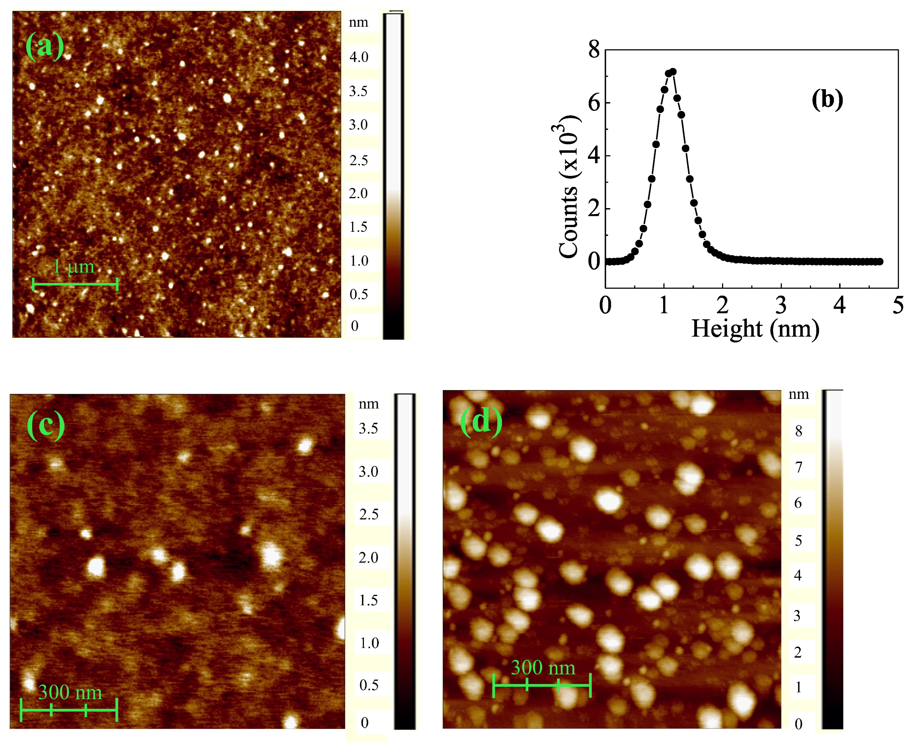
Mean diameter and aggregation performance of cobalt nanoparticles in our PLD setup were investigated by AFM topography. First, an estimation of their mean cluster diameter, D, was accomplished at some point of a wedged Co nanocluster assembly, where its thickness was ∼2 nm (according to shown results in Figure 2). Resulting AFM scan ( 4 × 4 μ m 2 ) shows a disordered spread of cluster assemblies (Figure 3a). Their mean D can be estimated from an statistical analysis of island height, which has been included as Figure 3b. For this calculation, z-values (or heights) referred to the baseline, i.e., the initial signal value at the AFM photodetector or, equivalently, its ground level during scanning. After this relative mode of topography analysis, the resulting histogram shows a clear maximum at around 1.5 nm, with this value corresponding with the height of most of the assemblies. As we assume these assemblies are formed mostly by one-cluster-thick layer, the mean assembly height must be equal to the diameter D of individual clusters. The measured value of cluster diameter D is quite smaller than that reported about Co assemblies grown by different techniques, e.g., molecular beam epitaxial or plasma–gas condensation [18,25,26]. Not surprisingly, the collimated beam in PLD provides a huge energy density at the Co target surface and evaporates a distribution of very fine particles. Due to high kinetic energy and the vacuum environment, these fine particles arrive at the substrate without a significant rate of aggregation, enabling us to deposit small Co nanoclusters [24]. Figure 3c,d concern aggregation and growth of cluster assemblies for two locations on the wedge assembly with different thicknesses, and selected on initial stages of the formation of thickness gradient (approximately 2 and 5 nm). At a reduced scanning scale of 1 × 1 μ m 2 , those AFM images give us an idea of the growth mechanism for such terraces at higher thickness. In the case of t 2 nm, only a few wide assemblies stand out with a height about 2 nm or higher, and most film is hardly seen as a set of interconnected assemblies. However, as t increases, different assemblies with increasing area and height can be clearly observed in Figure 3d. As the aggregation process of nanoclusters is more intense, growing islands are progressively wider in the substrate plane, and with augmenting height due to the stacking of additional terraces.

3.3. Magneto-Optical Effect in Reflection Configuration

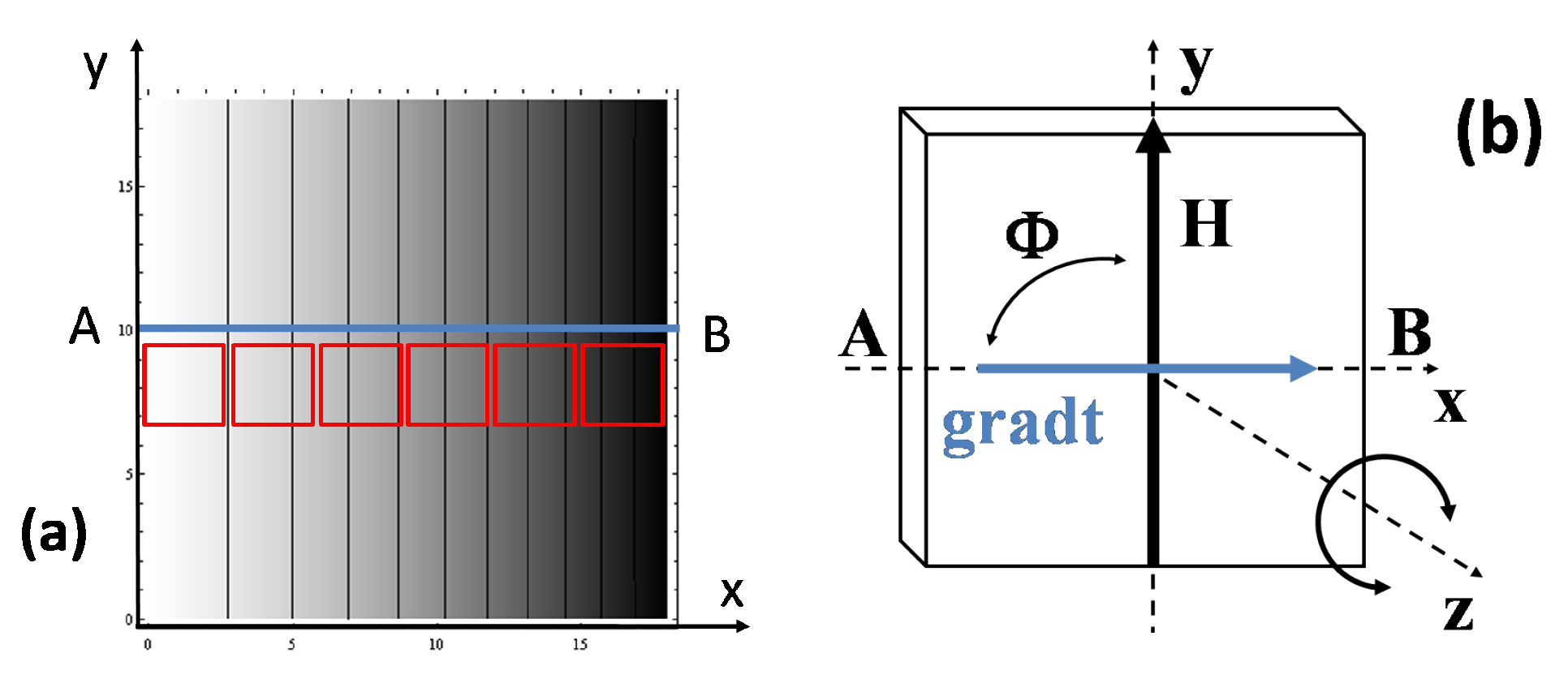
Considering the existence of a strong thickness gradient along AB direction in our Co nanocluster assemblies, we proceeded with the study of their MOKE. Previously, that wedged sample was cut in six small squares, with an appropriate size for the electromagnet gap. Hereafter, these pieces are labeled as P1 to P6 from A to B points (see density plot in Figure 4). The thickness of the Co nanocluster assembly at the center of each small piece is listed in Table 1.
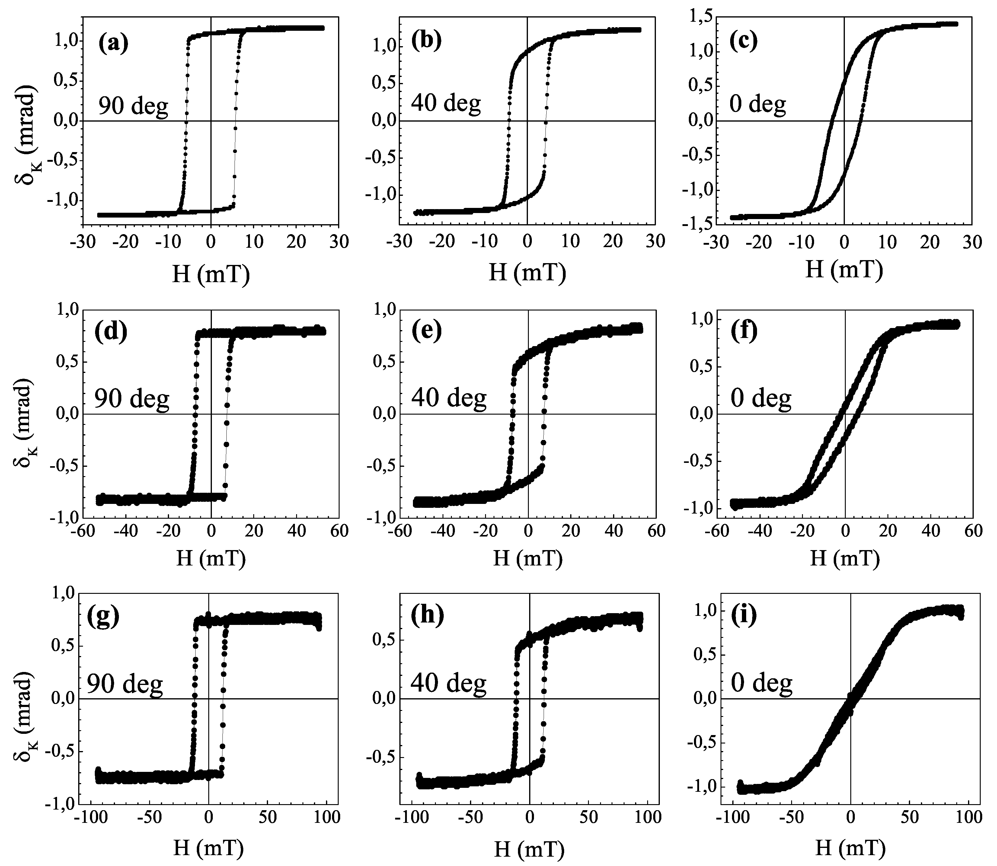
The corresponding vectorial MOKE was measured in P1–P6 pieces of that wedge sample to investigate, on one hand, the dependence of M on the relative orientation between H and the gradient direction, Φ (see axes and angle diagram in Figure 4), and on the other hand, on t along AB direction. All magneto-optic Kerr effect loops are consistent with a collective magnetic behavior associated with the cluster assemblies which are large enough to have a ferromagnet-like magnetization. Concerning the M L component, resulting hysteresis loops and the angular dependence of Kerr rotation angle, δ K have been found to be practically identical for P6 and P5, and very similar between P3 and P2. In the case of P1 (ultrathin Co nanocluster assembly), the required external field for magnetic saturation exceeded H m a x , pointing to an M o u t component ruled by a strong perpendicular magnetic anisotropy (PMA). Thus, and for the sake of brevity, we have selected δ K cycles for Φ = 0 , 40 and 90 for P6, P4, and P3. However, summarized results for P5 and P2 can be found in the Supplementary Material. It is readily seen in Figure 5 how the δ K (H) loop evolves from open to closed shape as H direction changes from perpendicular to parallel to the gradient direction, respectively. As H is applied perpendicular to that TGD, i.e., constant thickness at Φ = 90 , Co nanoclusters are progressive and magnetically coupled along the substrate plane, yielding a square δ K (H) loop. Contrarily, a closed hysteresis cycle is found at Φ = 0 , suggesting the thickness gradient to play a dominant role as a new magnetic anisotropy source in our Co nanocluster assemblies. In the case of P6 and P4, that dominance is gradual with decreasing t, yielding a partially closed δ K (H) loop. However, as the bulk contribution to M is strongly decreased in P3, the hysteresis cycle is completely closed, evidencing the appearance of a different mechanism for magnetization reversal as H is parallel to TGD, in comparison with open cycles.
In addition, for P3 piece, M T cycles have been measured for H orientation in the angular interval of ± 20 around that gradient direction. The corresponding results shown in Figure 6 evidence a reversing M under a coherent rotation process, pointing to the thickness gradient as responsible for an eventual out-of-plane magnetization in our samples.
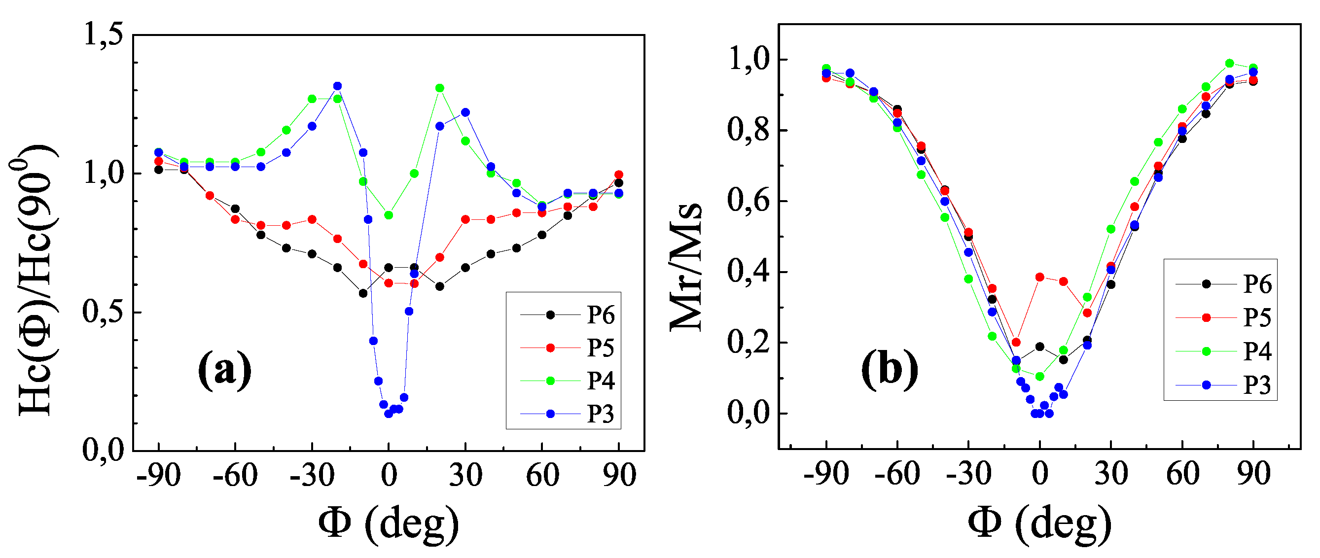
An extended study of the Φ dependence of both coercive field, H C , and normalized remanent magnetization is included in Figure 7, comparing the results for P3, P4, P5, and P6. As Φ tends to zero, the normalized coercive field decreases smoothly for P5 and P6 (thick Co nanocluster assemblies). The abrupt decrease of H C at Φ = 0 is slightly outlined in P4. Only for P3 (thin Co nanocluster assembly) does H C vanish virtually when H is applied parallel to TGD. This is also the case for the angular dependence of the normalized remanence, displaying a more pronounced decrease to zero. In our opinion, both graphs clearly show a uniaxial anisotropy of M L , arising at Φ = 0 and complete only for P3. Here, t reaches its lowest value in those studied samples, and gradt allows out-of-plane magnetization to overcome the weakened in-plane contribution to M. This reinforces our hypothesis for the gradient direction as responsible for that coherent reversal of magnetization, behaving as a magnetic anisotropy axis.

3.4. Magneto-Optical Effect in Transmission Configuration

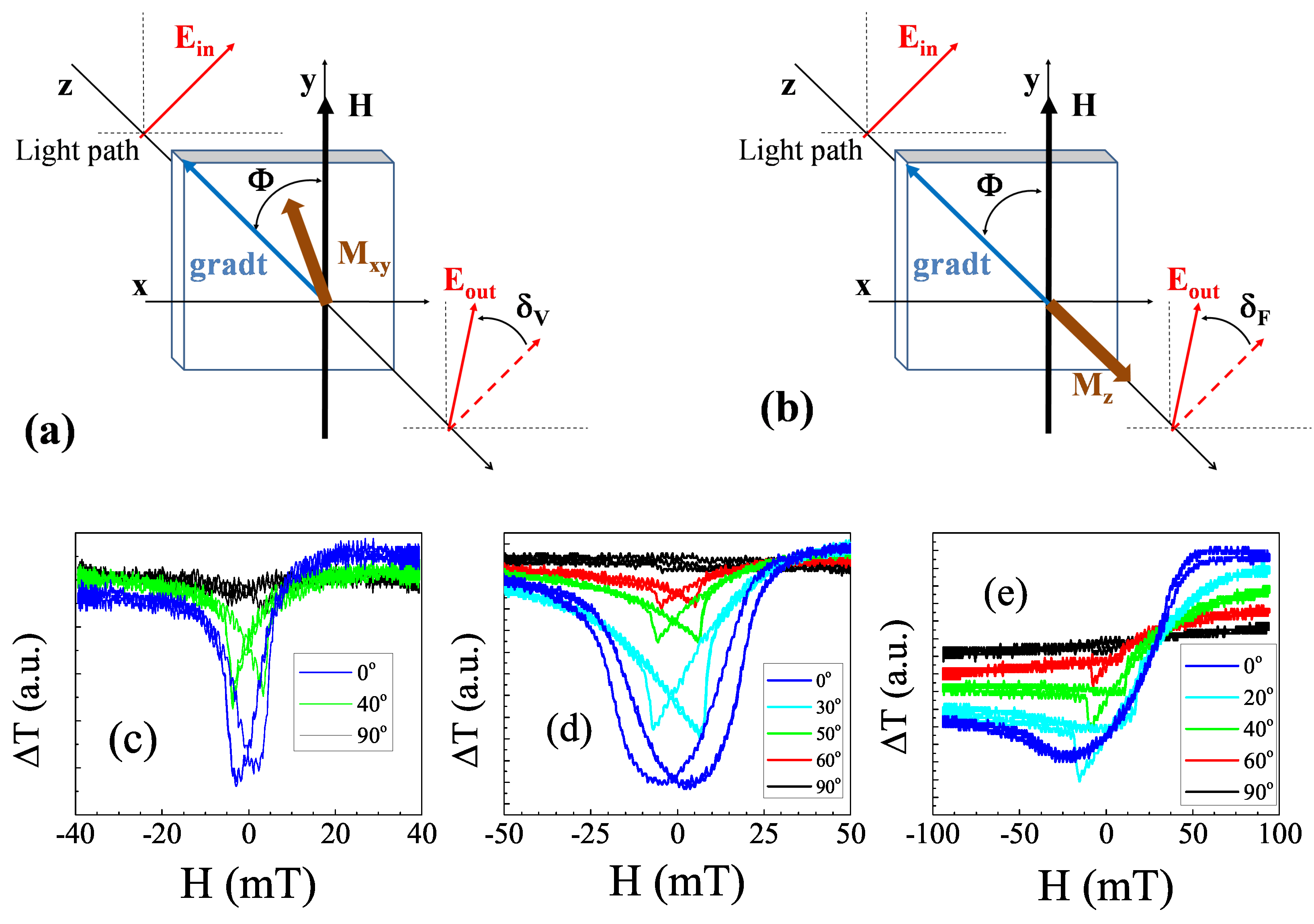
To obtain further insight into the reversal process of M as in-plane H is applied along the gradient direction, we investigated the magneto-optical effect in transmission configuration for our wedge sample. The so called Voigt effect (MOVE) is particularly sensitive to any source of magnetic anisotropy existing in the in-plane M, i.e., M x y component in the corresponding rays diagram of Figure 8.
As the transmitted light travels across the sample, its refraction index, n, depends on the relative orientation between its polarization plane and H direction. That yields a rotation angle of the electric field plane, δ V Re ( n n ), as E field is parallel or perpendicular to H [8]. This magnetic linear birefringence arises in magnetic 2D systems showing different mechanisms to reverse their magnetization along easy and hard magnetic axes [8,10]. From the experimental point of view, MOVE appears as intensity changes proportional to Δ T = T − T in the transmitted light. As the sample is driven along its easy axis, Δ T = 0 because M is reversed due to nucleation and growth of 180 domains in the sample plane. On the contrary, as H is applied off the easy axis, a magnetization contribution to M arises in the hard axis, with a different reversal mechanism, i.e., coherent rotation. This would lead us to detect MOVE effect as two symmetric and identical intensity peaks located at ±H C values [8,10].
In that transmission configuration, obtained results for P3, P4, and P6 pieces of our nanocluster 2D assembly are shown in Figure 8. First, no MLB is displayed as H is perpendicular to the gradient direction, pointing to a magnetization reversal process in the sample plane. Secondly, as H aligns progressively with the gradient direction, the recorded signals show two small anomalies near ±H C values, but superimposed to a background signal whose intensity increases noticeably as Φ approaches zero. According to the above introduction, this last and unexpected contribution cannot arise from a pure Voigt effect, only sensitive to in-plane magnetization reversal, but from a gradual appearance of an out-of-plane contribution to M, M z , in our Co nanocluster assemblies. In this transmission configuration, M z would orientate normal to the sample plane and parallel to the light path (see the corresponding rays diagram in Figure 8). Accordingly, M z should yield a Faraday rotation angle in the polarization plane of the emerging light, δ F , well known as the magneto-optical Faraday effect (MOFE). Therefore, the magneto-optical effect measured here in transmission configuration with in-plane H really shows a superposition of MOVE and MOFE.

4. Discussion

In the light of results shown in Section 3.4, the detailed investigation of MLB and the origin of M z in our Co cluster assemblies requires an additional analysis of those δ raw data, shown in Figure 8. In general terms, for an electromagnetic wave propagating through a ferromagnetic medium, its dielectric tensor can be expanded in powers of H. Limiting ourselves to first- and second-order terms, MOVE depends on M 2 , while MOFE is linear with the magnetization [7,27]. Thus, these even and odd contributions can be extracted from to the δ raw data of Figure 8 after applying the following symmetry relations:
δ ( F / V ) = [ δ i n c ( H ) δ d e c ( H ) ] / 2
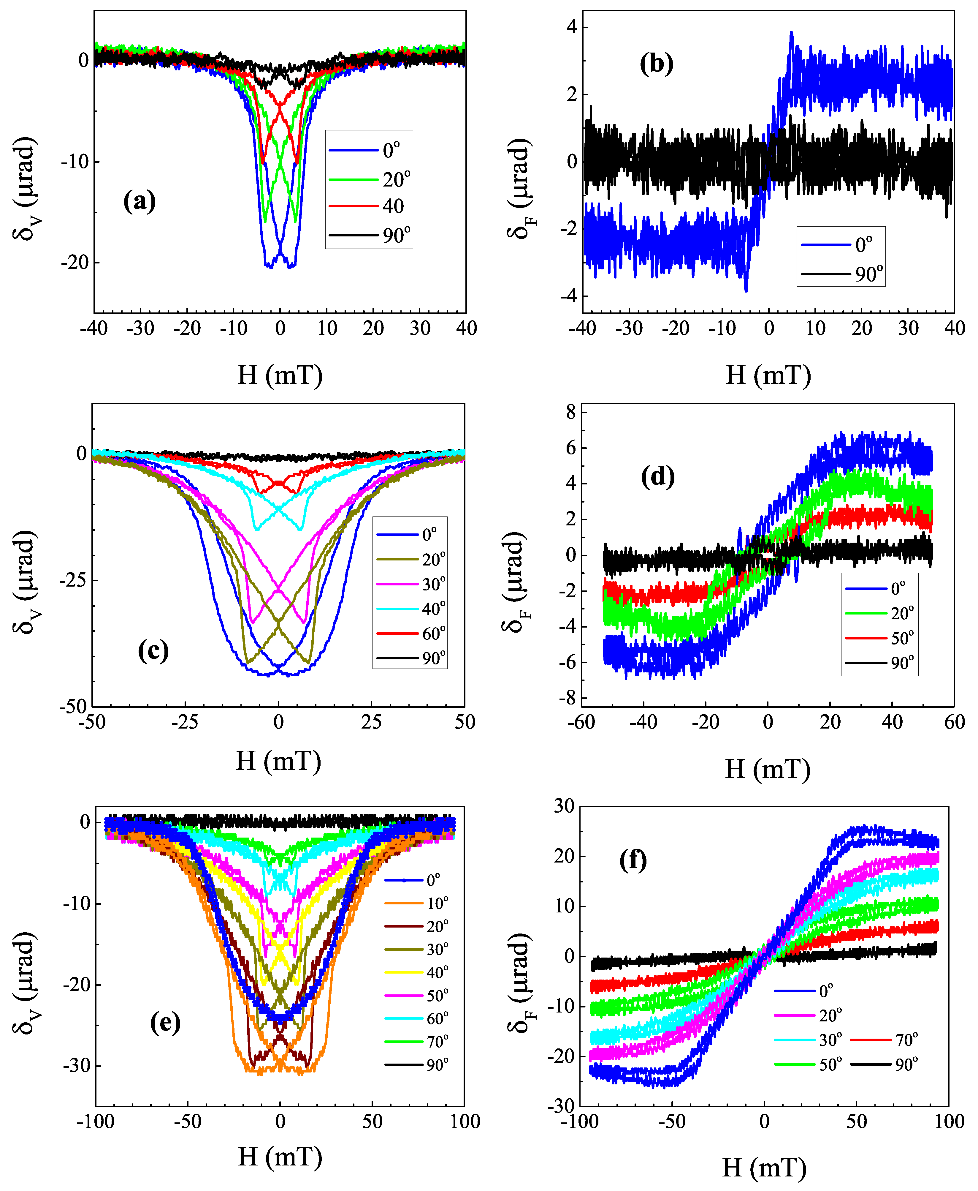
where δ ( i n c / d e c ) denotes the loop branch of δ when H is increasing or decreasing, respectively [28,29]. The resulting δ V and δ F loops for P6, P4, and P3 are shown in respective graphs of Figure 9. Summarized data for P5 and P2 are included in the Supplementary Material. First, the predicted two intensity peaks in MOVE are clearly seen now, their magnitude increasing as both H and TGD tend to be coincident ( Φ = 0 ). That turns that direction into an effective anisotropy axis, where M reversal is conducted perpendicular to the Co nanocluster assembly and completely different to the easy axis ( Φ = 90 ) [10,30]. The progressive approach of those peaks indicates an increasing dominance of the coherent rotation to reverse M, as H is parallel to TGD. For P3, they are merged in a single peak at Φ = 0 , showing an ideal magnetic linear birefringence [8]. Similar results can also be observed in P2. In these cases, both easy and hard axes are univocally related to respective perpendicular and parallel directions to gradt. Thus, the existence of MLB and UMA in our ultrathin Co nanoclusters assemblies, and its close relation with that thickness gradient, can be definitively settled after measuring and correlating their MOKE and MOVE.
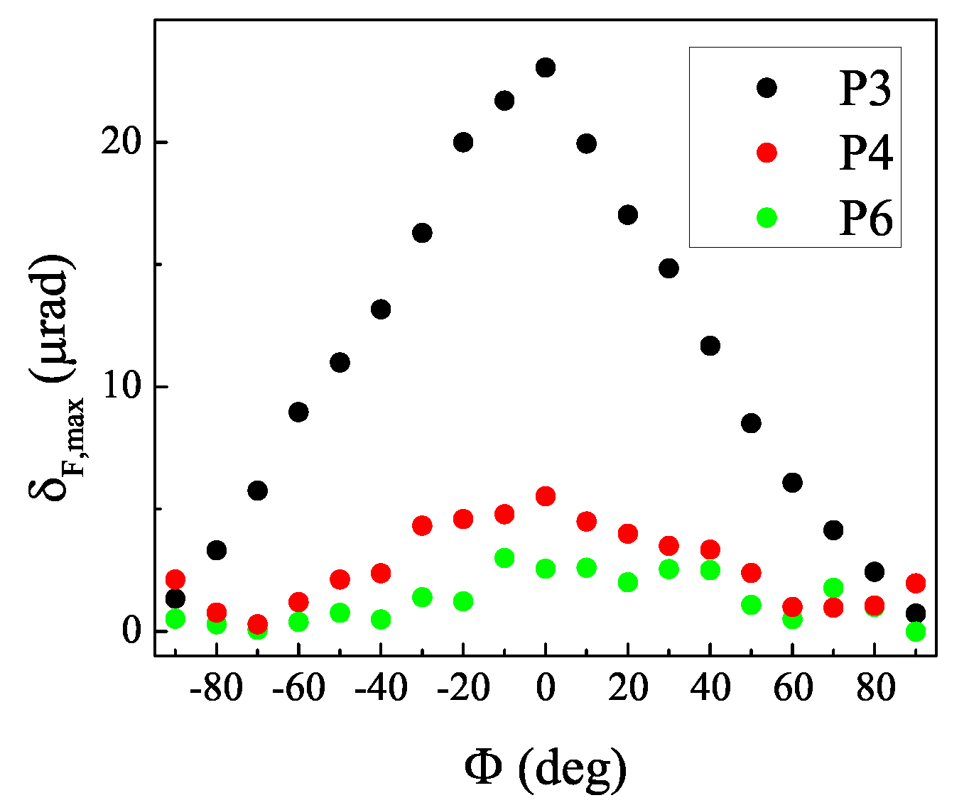
Additionally, these MOFE results show a novel evidence of emerging M z under in-plane magnetic field for disordered 2D magnetic media, not reported previously in the literature concerning ordered two-dimensional systems or Co cluster assemblies, and should require an additional discussion to explain those Faraday loops. D. Suess found the possibility to tune the magnetization orientation in multilayers, by means of a graded magnetic anisotropy among alternate layers along z-axis [20]. Later, that method was extended to continuous films, where that graded anisotropy could be achieved with growing samples with a compositional gradient, and subsequently a graded magnetization [31,32]. Basically, the magnetization orientation resulted from a competition between soft and hard magnetic layers, whose magnetic exchange could be tuned with some of those grading methods. In our work, the previous discussions of MOKE and MOVE data showed the thickness gradient to be a source of magnetic linear birefringence and UMA. Particularly, the magnitude of both effects has been proved to increase strongly upon decreasing thickness along TGD. Thus, the thickness gradient also yields a graded magnetization in z-axis, weakening the in-plane magnetic anisotropy and allowing the occurrence of a subtle M z contribution. This small out-of-plane magnetization is enough to give a detectable Faraday rotation, as seen in Figure 9. We have measured M z with MOFE only for P3 and P2 samples of 2.3 and 5.4 nm average thickness, respectively, i.e., for intermediate values of thickness. Too-thin pieces in the graded coating comprise isolated cluster assemblies randomly spread over the substrate, whereas the too-thick pieces must be formed from a continuous stack of clusters. Thus, it seems that a film morphology of interconnected cluster assemblies—as an intermediate case once coalesce occurs—can be appropriate for the appearance of magnetic effects, leading to a minor but detectable out-of-plane magnetization. The physical origin of the minor M z could arise from magnetic coupling of nanoclusters along terrace edges in this scenario. To speculate with the origin of out-of-plane component, we should recall similar magnetic phenomena: patterned planar arrays of interconnected dots/antidots have shown composite in-plane and out-of-plane magnetizations under in-plane applied fields due to the effect of geometric frustration of moments at the network nodes [33]. Our assembly system develops a minor out-of-plane magnetization and a dominant in-plane magnetization, under in-plane fields along TGD, the former one probably developed at a few nodes where the neighboring (in-plane) assembly moments point oppositely to each other. As these are expected to be scarce, this speculative explanation is difficult to microscopically confirm. For the intermediate thickness range, e.g., P3 of our Co nanocluster assembly, the maximum magnitude of Faraday rotation and, consequently, the MLB is reached at Φ = 0 , as seen in Figure 10, where a comparative study of δ F has been accomplished for P3, P4, and P6.
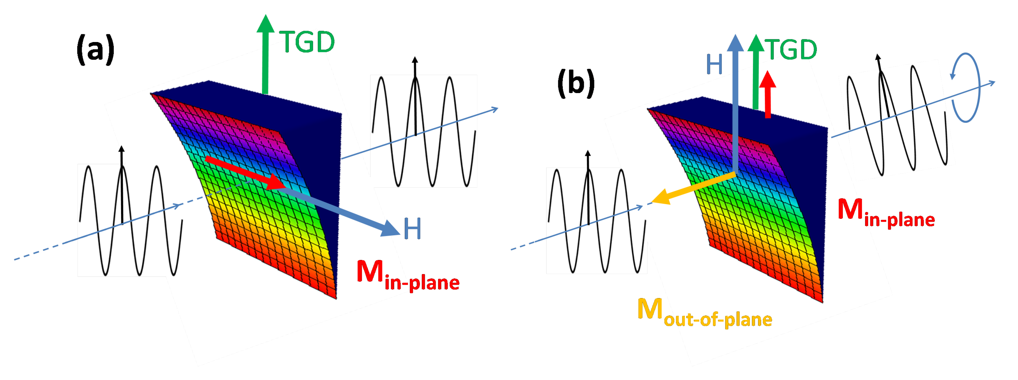
Despite everything, the measurement of magneto-optical effects in transmission configuration has evidenced its capability to detect and monitor subtle thickness irregularities in our wedge assemblies, helping us to map the magnetization vector over the surface sample. Accordingly, this effect enables this 2D system to finely alter the polarization plane of the transmitted light, behaving as a polarization filter or rotator (sketched in Figure 11). Either for fundamental or applied applications, the improvement of the magnitude and accuracy of both magnetic linear birefringence and Faraday rotation, i.e., M o u t , needs further research on tailoring the profile and sharpness of thickness gradient in these 2D nanocluster assemblies.

Supplementary Materials

The following supporting information can be downloaded at: https://www.mdpi.com/article/10.3390/app12010100/s1.

Author Contributions

Conceptualization, M.A.A.; methodology, M.A.A., E.H.S. and J.M.C.; formal analysis, M.A.A., E.H.S., J.M.C. and V.R.-D.; investigation, M.A.A. and V.R.-D.; resources, M.A.A., J.L.S.-R. and J.M.C.; data curation, M.A.A., E.H.S. and J.M.C.; writing—original draft preparation, M.A.A., E.H.S. and J.M.C.; writing—review and editing, all authors; acquisition, M.A.A. All authors have read and agreed to the published version of the manuscript.

Funding

This research was funded by Spanish Ministry of Economy and Competitiveness, (MINECO, grant number UNCM08-1E-024), Spanish Ministry of Science and Innovation (MCIN, grant number MCIN/AEI/ 10.13039/501100011033) and FEDER “ERDF A way of making Europe” (grant number RTI18-094960-B-100).

Institutional Review Board Statement

Not applicable.

Informed Consent Statement

Not applicable.

Data Availability Statement

The data that support the findings of this study are available from the corresponding author upon reasonable request.

Conflicts of Interest

The authors declare no conflict of interest.

Abbreviations

The following abbreviations are used in this manuscript:
PLAPulsed laser ablation
TGDThickness gradient direction
UMAUniaxial magnetic anisotropy
MLBMagnetic linear birefringence
MOKEMagneto-optical Kerr effect
MOFEMagneto-optical Faraday effect
MOVEMagneto-optical Voigt effect

References

  1. Chen, X.Y.; Lu, Y.F.; Cho, B.J.; Zeng, Y.P.; Zeng, J.N.; Wu, Y.H. Pattern-induced ripple structures at silicon-oxide/silicon interface by excimer laser irradiation. Appl. Phys. Lett. 2002, 81, 1344–1347. [Google Scholar] [CrossRef] [Green Version]
  2. Harzic, R.L.; Schuck, H.; Sauer, D.; Anhut, T.; Riemann, I.; König, K. Sub-100 nm nanostructuring of silicon by ultrashort laser pulses. Opt. Express 2005, 13, 6651–6655. [Google Scholar] [CrossRef] [PubMed]
  3. Arranz, M.A.; Sánchez, E.H.; Rebollar, E.; Castillejo, M.; Colino, J.M. Form and magnetic birefringence in undulated Permalloy/PET films. Opt. Express 2019, 27, 21285–21294. [Google Scholar] [CrossRef]
  4. Richter, S.; Miese, C.; Döring, S.; Zimmermann, F.; Withford, M.J.; Tünnermann, A.; Nolte, S. Laser induced nanogratings beyond fused silica-periodic nanostructures in borosilicate glasses and ULETM. Opt. Mat. Express 2013, 3, 1161–1166. [Google Scholar] [CrossRef] [Green Version]
  5. Yang, P.; Burns, G.R.; Guo, J.; Luk, T.S.; Vawter, G.A. Femtosecond laser-pulse-induced birefringence in optically isotropic glass. J. Appl. Phys. 2004, 95, 5280–5283. [Google Scholar] [CrossRef]
  6. Ali, M. Growth and Study of Magnetostrictive FeSiBC thin Films for Device Applications. Ph.D. Thesis, University of Sheffield, Sheffield, UK, 1999. [Google Scholar]
  7. Sokolov, A. Optical Properties of Metals, 1st ed.; Blackie: London, UK, 1967. [Google Scholar]
  8. Carey, R.; Thomas, B.W.J.; Viney, I.V.F.; Weaver, G.H. Magnetic birefringence in thin ferromagnetic films. J. Phys. D 1968, 1, 1679. [Google Scholar] [CrossRef]
  9. Moroni, R.; Sekiba, D.; de Mongeot, F.B.; Gonella, G.; Boragno, C.; Mattera, L.; Valbusa, U. Uniaxial magnetic anisotropy in nanostructured Co/Cu(001): From surface ripples to nanowires. Phys. Rev. Lett. 2003, 91, 7027–7030. [Google Scholar] [CrossRef]
  10. Arranz, M.A.; Colino, J.M. Angular tuning of the magnetic birefringence in rippled cobalt films. Appl. Phys. Lett. 2015, 106, 3102–3105. [Google Scholar] [CrossRef]
  11. Carcia, P.F.; Mcinhaldt, A.D.; Suna, A. Perpendicular magnetic anisotropy in Pd/Co thin film layered structure. Appl. Phys. Lett. 1985, 47, 178–180. [Google Scholar] [CrossRef]
  12. Johnson, M.T.; Bloemen, P.J.H.; den Broeder, F.J.A.; de Vries, J.J. Magnetic anisotropy in metallic multilayers. Rep. Prog. Phys. 1996, 59, 1409–1458. [Google Scholar] [CrossRef]
  13. Jungblut, R.; Johnson, M.T.; aan de Stegge, J.; Reinders, A.; den Broeder, F.J.A. Orientational and structural dependence of magnetic anisotropy of Cu/Ni/Cu sandwiches: Misfit interface anisotropy. J. Appl. Phys. 1994, 75, 6425. [Google Scholar] [CrossRef]
  14. Gradmann, U. Surface Magnetism. J. Magn. Magn. Mater. 1991, 100, 481–496. [Google Scholar] [CrossRef]
  15. Nguyen, T.V.A.; Shiratsuchi, Y.; Sato, H.; Ikeda, S.; Endoh, T.; Endo, Y. Magnetic properties of Co film in Pt/Co/Cr2O3/Pt structure. AIP Adv. 2020, 10, 015152. [Google Scholar] [CrossRef] [Green Version]
  16. Kisielewski, M.; Maziewski, A.; Kurant, Z.; Tekielak, M.; Wawro, A.; Baczewski, L.T. Magnetic ordering in ultrathin cobalt film covered by an overlayer of noble metal. J. Appl. Phys. 2003, 93, 7628. [Google Scholar] [CrossRef]
  17. Jamal, M.S.; Guptab, P.; Kumara, D. Preferential alignment of Co moments at Oxide/Co interface in Si/Co/Co-oxide/CoWedge/Pt structure. Thin Solid Films 2020, 709, 138246. [Google Scholar] [CrossRef]
  18. Stupakiewicz, A.; Maziewski, A.; Matlak, K.; Spiridis, N.; Ślȩzak, M.; Ślȩzak, T.; Zaja, M.; Korecki, J. Tailoring of the Perpendicular Magnetization Component in Ferromagnetic Films on a Vicinal Substrate. Phys. Rev. Lett. 2008, 101, 217202. [Google Scholar] [CrossRef] [PubMed]
  19. Laidler, H.; Hickey, B.J. Anisotropy of an ultrathin Cu(111)/Co(111)/Cu(111) wedge. J. Phys. Condens. Matter 2000, 12, 8401–8410. [Google Scholar] [CrossRef]
  20. Suess, D. Multilayer exchange spring media for magnetic recording. Appl. Phys. Lett. 2006, 89, 113105. [Google Scholar] [CrossRef]
  21. Kirby, B.J.; Davies, J.E.; Liu, K.; Watson, S.M.; Zimanyi, G.T.; Shull, R.D.; Kienzle, P.A.; Borchers, J.A. Vertically graded anisotropy in Co/Pd multilayers. Phys. Rev. B 2010, 81, 100405. [Google Scholar] [CrossRef] [Green Version]
  22. Arranz, M.A.; Colino, J.M.; Palomares, F.J. On the limits of uniaxial magnetic anisotropy tuning by a ripple surface pattern. J. Appl. Phys. 2014, 115, 3906–3914. [Google Scholar] [CrossRef] [Green Version]
  23. Palik, E.D. The use of polarized infrared radiation in magneto-optical studies of semiconductors. Appl. Opt. 1963, 2, 527. [Google Scholar] [CrossRef]
  24. Krebs, H.U. Pulsed Laser Deposition of Thin Films. Applications-Led Growth of Functional Materials, 1st ed.; Chapter 16: Pulsed Laser Deposition of Metals; Wiley: Hoboken, NJ, USA, 2007; p. 363. [Google Scholar]
  25. Yamamuro, S.; Sumiyama, K.; Kamiyama, T.; Suzuki, K. Morphological and magnetic characteristics of monodispersed Co-cluster assemblies. J. Appl. Phys. 1999, 86, 5726. [Google Scholar] [CrossRef]
  26. Stupakiewicz, A.; Fleurence, A.; Maziewski, A.; Maroutian, T.; Gogol, P.; Bartenlian, B.; Mégy, R.; Beauvillain, P. Magnetization Processes in Ultrathin Co Film Grown on Stepped Si(111) Substrate. IEEE Trans. Magn. 2008, 44, 2887. [Google Scholar] [CrossRef]
  27. Vinogradov, A.; Dorofeenko, A.; Merzlikin, A.; Strelniker, Y.; Lisyansky, A.; Granovsky, A.; Bergman, D. Magnetophotonics: From Theory to Applications, 3rd ed.; Springer: Berlin/Heidelberg, Germany, 2013; p. 24. [Google Scholar]
  28. Muduli, P.; Rice, W.; He, L.; Collins, B.; Chu, Y.; Tsui, F. Study of magnetic anisotropy and magnetization reversal using the quadratic magnetooptical effect in epitaxial CoxMnyGez(111) films. J. Phys. Condens. Matter. 2009, 21, 296005. [Google Scholar] [CrossRef]
  29. Hamrle, J.; Blomeier, S.; Gaier, O.; Hillebrands, B.; Schneider, H.; Jakob, G.; Postava, K.; Felser, C. Huge quadratic magneto-optical Kerr effect and magnetization reversal in the Co2FeSi Heusler compound. J. Phys. D Appl. Phys. 2007, 40, 1563. [Google Scholar] [CrossRef] [Green Version]
  30. Arranz, M.A.; Colino, J.M. Magnetooptical Voigt effect in rippled polycrystalline Co films. J. Phys. D Appl. Phys. 2016, 49, 5306–5313. [Google Scholar] [CrossRef]
  31. Fallarino, L.; Riego, P.; Kirby, B.; Miller, C.; Berger, A. Modulation of Magnetic Properties at the Nanometer Scale in Continuously Graded Ferromagnets. Materials 2018, 11, 251. [Google Scholar] [CrossRef] [Green Version]
  32. Zha, C.; Dumas, R.; Fang, Y.; Bonanni, V.; Nogués, J.; Åkerman, J. Continuously graded anisotropy in single (Fe53Pt47)100-xCux films. Appl. Phys. Lett. 2010, 97, 182504. [Google Scholar] [CrossRef] [Green Version]
  33. Gräfe, J.; Haering, F.; Tietze, T.; Audehm, P.; Weigand, M.; Wiedwald, U.; Ziemann, P.; Gawroński, P.; Schütz, G.; Goering, E.J. Perpendicular magnetisation from in-plane fields in nano-scaled antidot lattices. Nanotechnology 2015, 26, 225203. [Google Scholar] [CrossRef]
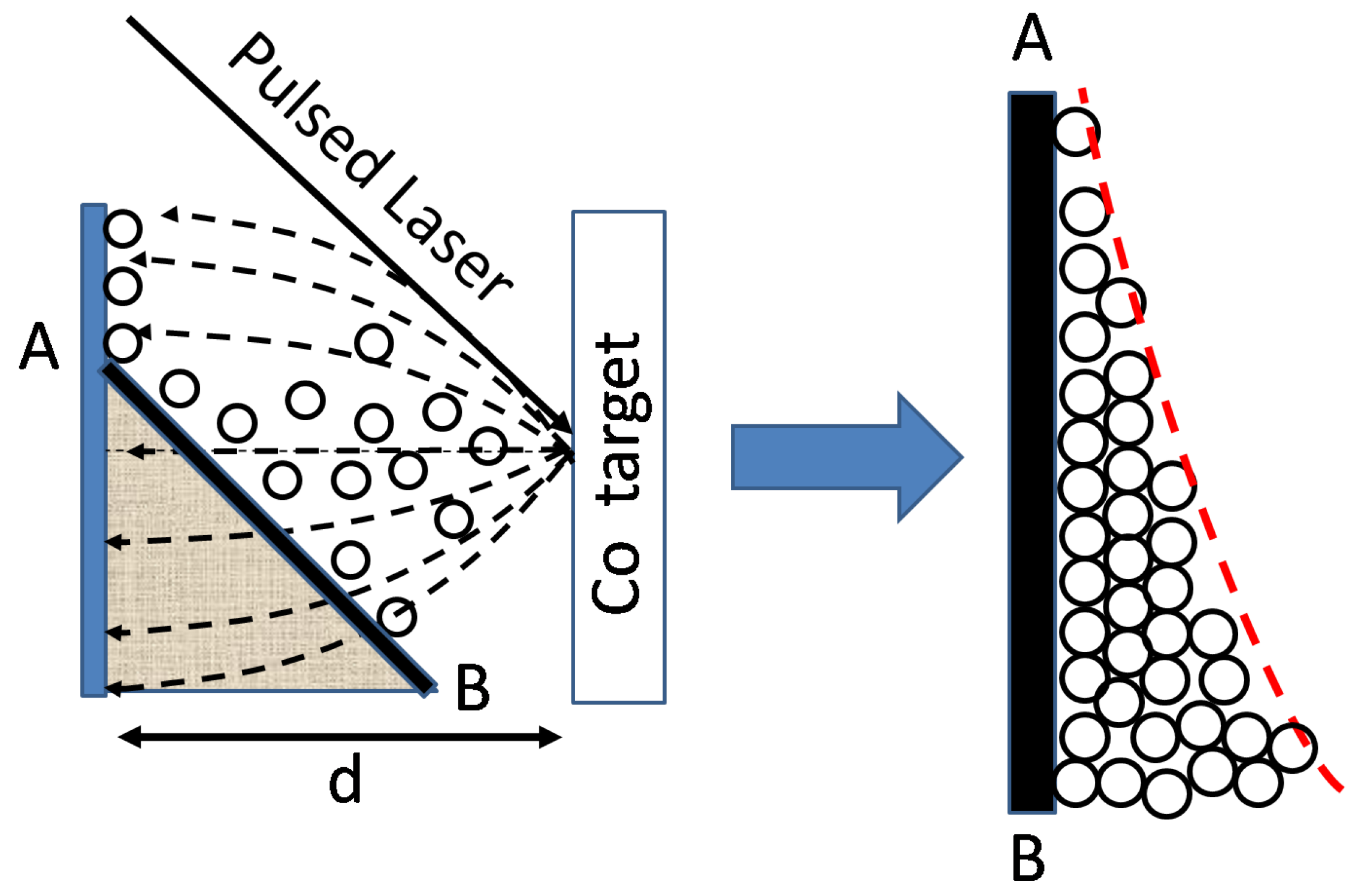
Figure 1. Sketch showing the deposition of a characteristic nanocluster 2D assembly under growing parameters indicated in the text. In this off-axis geometry, the glass substrate corresponds to the solid line AB. On the right, we show a simulated thickness profile of the grown Co assembly.
Applsci 12 00100 g001
Figure 2. (a) The density plot outlines the expected thickness gradient profile of our sample in off-axis geometry. Blue line AB corresponds to the selected direction for measuring the sample thickness. (b) 3D graph simulates the surface of the Co assembly along AB direction. Color bar scale is in nm. (c) Thickness profile measured along AB direction. Thickness resolution was ≤1 nm with our profilometer (see Supplementary Material for details).
Applsci 12 00100 g002
Figure 3. Panel of figures concerning AFM topographic characterization of our Co-cluster assemblies: (a,b) surface image and height distribution at t 2 nm, (c,d) reduced AFM scans at t 2 and 5 nm, respectively.
Applsci 12 00100 g003
Figure 4. (a) Red squares in the density plot correspond to the small pieces of the sample where their magneto-optical effects were measured in this work. Those pieces are numbered in the text as P1 to P6 from A to B position, respectively. (b) Axes and angle diagrams refer to the used definitions along the text for the angular dependence of magneto-optical effects in our Co nanocluster assembly.
Applsci 12 00100 g004
Figure 5. Dependence of Kerr rotation angle on the magnetic field and Φ angle for three locations on the Co nanocluster assembly: Panels (ac) correspond to P6, panels (df) to P4, and panels (gi) to P3, respectively. In all cases, Φ value is indicated in each panel.
Applsci 12 00100 g005
Figure 6. Panels (ae) correspond to the angular dependence of M T around the TGD in the Co nanocluster assembly labeled as P3. Respective Φ values are indicated inside each panel.
Applsci 12 00100 g006
Figure 7. Angular dependence of the (a) normalized coercive field and (b) remanence for four locations on the Co nanocluster assembly (P3 to P6).
Applsci 12 00100 g007
Figure 8. Panels (a,b) show respective rays and angle diagrams for MOVE and MOFE measurements in transmission configuration, where the light path is always along z-axis. Panels (ce) show the recorded intensity of the transmitted light at the differential amplifier circuit for P6, P4, and P3, respectively. In all cases, legends indicate Φ values.
Applsci 12 00100 g008
Figure 9. Dependence of Voigt and Faraday rotation angle on the magnetic field and Φ angle for three locations on the Co nanocluster assembly: Panels (a,b) correspond to P6, panels (c,d) to P4, and panels (e,f) to P3, respectively. In all cases, Φ value is indicated in each panel.
Applsci 12 00100 g009
Figure 10. Angular dependence of δ F , m a x for P3, P4, and P6. δ F , m a x refers to Faraday rotation at saturation magnetic field.
Applsci 12 00100 g010
Figure 11. The colored drawing resembles a 3D graph of a Co nanocluster assembly displaying a thickness gradient. Color scale bar is the same as shown in Figure 2b. According to shown MOFE results (Figure 9), the sketch (b) outlines the rotation of the E polarization plane in the light transmitting across that 2D assembly, when H is applied along its thickness gradient (M o u t 0 ). Contrarily, in the sketch (a) and for the incoming beam at the same point, MOFE vanishes as H is perpendicular to the thickness gradient (M o u t = 0 ).
Applsci 12 00100 g011
Table 1. Table indicates t values in respective square pieces used in the following characterization of magneto-optic effects. These values have been extrapolated from the measured thickness profile of the Co nanocluster assembly (see Figure 2).
SquareP1P2P3P4P5P6
Thickness (nm)1.582.325.4111.518.2624.66
Publisher’s Note: MDPI stays neutral with regard to jurisdictional claims in published maps and institutional affiliations.