Article

Real-Time Physical Prototyping Tool Design Based on Shape-Changing Display

1
RECON Labs Inc., Seoul 04778, Korea
2
Department of Interior Architecture Design, Hanyang University, Seoul 04763, Korea
*
Author to whom correspondence should be addressed.
Appl. Sci. 2021, 11(9), 4181; https://doi.org/10.3390/app11094181
Submission received: 24 March 2021 / Revised: 27 April 2021 / Accepted: 27 April 2021 / Published: 4 May 2021
(This article belongs to the Section Applied Industrial Technologies)

Abstract

:
Prototyping during the early design phases has become an essential part of conceptualization and product development. Recent advances in digital design tools have enabled active user participation in the design process and direct interaction with prospective products. Despite the rapid advancements in prototyping, immediate prototyping methods remain unavailable. Creating a working prototype and evaluating its user interactions is an effective design strategy. If a prototype can be created immediately for designers to sensorially experience a model, they can test and simulate various design ideas with immediate user feedback in the early design phases. Therefore, this paper aims to develop a real-time prototyping method that enables designers to evaluate a physical model of a design. Accordingly, we demonstrated a complete design and proof of concept for closed surface-based shape-changing displays (SCDs) that can assist designers in realizing conceptual design development. Experiments were conducted to verify the robustness and accuracy of the shapes displayed using the proposed SCD. Simulation-experiment results reveal that complex organic shapes (rabbits or human faces) and man-made shapes (chairs, cars, and buildings) could be accurately reconstructed using the proposed closed surface-based SCD with numerous actuators. Furthermore, an experiment with a physical SCD prototype (2V icosphere) demonstrated accurate reconstruction of the optimized shapes of a digital model.

1. Introduction

The prototyping process has become a significant part of the conceptualization and development of products during the early design phases [1,2]. Prototyping enables the simulation of a sample version of an idea in a highly visual and functional mockup for testing prior to finalizing the design [3,4]. The design process is an iterative loop of design activity [5]; therefore, it is important to explore and develop new design concepts through prototypes [6]. This can help designers predetermine the deployment of resources during product development, thereby influencing the success of the design project [7]. More importantly, prototyping enhances the quality of collaboration between the designers and users, affording a better understanding of the design concept [3]. Therefore, collaborations in the early design phases of idea generation have become a widespread practice [4]. Recent advances in digital design tools have enabled active user participation in the design process and direct interaction with potential products [8,9]. Users can make their own products through adaptable hardware interfaces and application programming interfaces instead of utilizing designers [10]. According to Ferrise et al. [11], the most effective design strategy is to create a working prototype and evaluate user interactions with the prototype. Designers can virtually create three-dimensional (3D) objects [12,13] and collaborate in a virtual environment to assemble them [14,15]; meanwhile, users can experience a digital 3D space while controlling visual information [16]. In addition, users can participate in new digital content and experience immersive virtual spaces [17]. Advancements in computer graphics have enabled sophisticated augmentation of the physical world with digital information; however, a discrepancy between the two still remains. Collaboration often involves physical tasks that require various levels of expertise [18]. During the design collaboration process, apart from visualizing the 3D objects, it is also necessary to touch, feel, and perceive information more intelligently and differently depending on the environment and circumstances.
VR (Virtual Reality) researchers have concentrated on inventing state-of-the-art methods to provide haptic feedback to generate a more immersive experience [19]. They have utilized airstream [20], handheld weight-shifting devices [21], stiffness suits [22], and wearable actuators [23]. However, none of these innovative inventions focus on providing a physical representation of the digital content, thereby allowing users to have a natural experience of creating a physical prototype. Researchers have utilized a tangible user interface (TUI) in the design process to simulate design prototypes intuitively by enhancing the tactile aspects during design development [24,25]. A major limitation of the TUI is its lack of modeling capability; therefore, most TUI applications use a predefined model and do not support real-time, free-form modeling [24]. Physical prototyping is an important part of the design process because it supports collaborations related to visual thinking [26]. According to Berni et al. [27], a physical prototype is advantageous in that its use increases the reliability of product evaluation, but it is resource- and time-intensive. In this respect, designers widely use rapid prototyping technologies, such as additive manufacturing (3D printer) and subtractive manufacturing (laser cutter, CNC miller), to create physical prototypes quickly. Rapid prototyping allows for fast evaluation of preliminary prototypes, which in turn provides designers with physical interaction with the model in the early design phase when the quality of the idea is essential [28]. In recent years, 3D printing technology has promoted the development of additive manufacturing industries [29,30]. The primary advantage of 3D printing is the efficiency of creating complex shapes that are otherwise difficult to produce. However, the iteration of generation and materialization of a design idea enables the exploration of potential novel design ideas [31]. According to Gonçalves et al. [32], designers actively collect physical and mental visual samples for inspirational purposes during the design ideation process. Gonçalves et al. [32] also found that professional designers highly rated three-dimensional representations as inspirational stimuli. Neeley et al. [28] tested the impact of rapid prototyping in the acceleration of design ideation process with 39 participants. Their results reveal that a group that created more prototypes exhibited improved design outcomes and higher satisfaction than those exhibited by the other group, who were only instructed to create one prototype. Viswanathan and Linsey [33] conducted experiments to test the sunk cost effect under five conditions—sketching only, metal-building, plastic-building, metal-constrained sketching, and plastic-constrained sketching—in the idea generation process. The results confirm that building a physical model significantly helped improve the design quality, and the decreased effort in creating the prototype (e.g., a quick model-making process) led to comparatively less design fixation. Even though the technology is called rapid prototyping, the 3D printing process is slow and requires overnight printing of a reasonable-sized model [34]. In this respect, researchers have attempted to streamline rapid prototyping speeds. Mueller et al. [34] proposed a WirePrint system that constructs low-fidelity wireframe previews that significantly reduces the printing duration. Kohtala and Steinert [35] incorporated a laser cutting file-making process with hand sketches to streamline the subtractive manufacturing process. However, despite the advancements in rapid prototyping technologies, methods that enable immediate physical prototyping have been thoroughly researched. If a prototype can be created instantly for designers to sensorially experience a model, they can test and simulate various design ideas during the early design phases.
In contrast, a shape-changing display (SCD) can dynamically reconstruct digital information through physical changes, thus enabling real-time prototyping. The shape and volume of the SCD change by extruding the actuator. SCDs provide haptic feedback by transforming a shape through a combination of actuating pins that exert physical force. Thus, unlike conventional rapid prototyping and VR-based prototyping technologies, the SCD can construct a physical prototype in real time. In Iwata et al. [36], the visualization of a terrain using 16 actuators to create various 2.5D models with FEELEX has been discussed. Previous studies on SCDs have mainly used tabletop SCDs composed of a series of linear actuators extruding in a single axis and could reconstruct the shape of a surface. SCDs can be used in various applications and are compatible with numerous screen technologies. For example, various shapes can be reconstructed through the display [37], and texture mapping can be used to represent information on a display screen [38]. This demonstrates the potential of SCDs to deliver rich content without physical constraints. Existing state-of-the-art reports on SCDs highlight their numerous possible applications in human–computer interaction; however, tabletop SCDs have morphological limitations. For example, certain tasks are analogous to drawing a picture on a curved wall; however, 3D objects require a closed surface-based reconstruction method for morphological robustness.
Unlike the systems proposed in previous literature, we propose a closed surface-based SCD that reconstructs a shape based on a series of linear actuators. Specifically, the display deforms the surface by arranging the actuators radially around a single point. To the best of our knowledge, this is the first study to develop a closed surface-based SCD that instantly constructs a physical prototype of 3D digital models, thereby enabling 360° evaluations. The aim of this study was to accurately and instantly reconstruct 3D digital models physically to ensure that designers can interactively simulate and evaluate the modifications in various design alternatives during the early design phase. Accordingly, our research demonstrates a complete system of closed surface-based SCDs for real-time prototyping to facilitate the development of conceptual designs. Six primary tasks were performed to accomplish this objective. First, a novel SCD proof of concept that can change its surface using radially arranged actuating pins modeled on an icosphere was developed. Second, an optimization method was developed to determine the number and placement of actuating pins required to reconstruct shapes with SCD. Third, an algorithm that optimizes digital 3D models on various closed-surface-based SCDs was created. Finally, a series of validation experiments were conducted to determine the accuracy of the shapes displayed using the proposed SCD.

2. Related Work

2.1. Advancements in Prototyping Tools

Lim et al. [39] defined prototypes as “filters that traverse a design space and are manifestations of design ideas that concretize and externalize conceptual ideas.” Prototyping is an important process for identifying design flaws and testing usability in the early design phases. The introduction of rapid prototyping significantly reduced the prototype production time from weeks to several hours [40]. Time is a critical element in the design process because a design change in the early phase is significantly cheaper than that in the later phases [41]. Researchers in the domain of prototyping have attempted to reduce time, effort, and cost by incorporating digital displays, such as augmented and virtual reality [25,32,33,34,35,36,37,38,39,40,41,42,43,44]. Seth et al. [44] utilized a haptic feedback interface to create an interface for virtual assembly. They developed a system for haptic assembly and realistic prototyping (SHARP) composed of dual PHANToM® haptic devices. The results of their study indicated that the integration of SHARP resulted in faster product development, faster identification of design issues, and lower cost in the design process. In addition, the system can support various virtual reality systems. Ban and Hyun [45] proposed directional force feedback to provide haptic feedback to mimic the inertial experience during VR sessions. Kim et al. [43] utilized a TUI and developed “miniStudio” to prototype ubicomp spaces with proxemic interactions. Their system utilized projection mapping to augment physical models in order to enable tangible interactions and dynamic representations. However, the physical model must be created manually, which requires new prototypes in different contexts. Although problems remain, Kim et al. [43] suggested a method for reflective prototyping in a ubicomp space. Nasman and Cutler [25] utilized a TUI and virtual reality to simulate daylight conditions on indoor environment prototypes. The daylight design is considered important in space designs because it attempts to balance the amount of daylight with an appropriate number of windows. In addition, it is difficult to imagine daylight conditions in a designed space. C-Space, developed by Son et al. [46], enables designers to collaborate on a shared AR and TUI-based platform, where spatial designers can quickly create design prototypes. More importantly, C-Space provides design references for existing buildings according to the prototypes assembled by users. Thus, users can collaboratively develop designs if they have an understanding of the previous design examples. However, Son et al. [46] proposed an intuitive prototyping and case-based reasoning tool, wherein the prototyping system is based on a TUI that does not support real-time, free-form modeling. Therefore, users can only utilize predefined models for the TUI. Park et al. [47] proposed a method for prototyping digital handheld products through an AR-based TUI. They utilized rapid prototyping and paper-based modeling for AR-based tangible objects for the rapid production of prototyping interfaces. Barbieri et al. [48] proposed a method for testing the usability of products through mixed reality-based prototyping. Specifically, they created a physical prototype with AR markers and created a mixed-reality environment in which users can touch physical interfaces, such as the knobs and buttons of home appliances. Li et al. [49] developed the “Robot Mannequin,” a shape-changing robot that can modify its physical appearance based on an input 3D model. The Robot Mannequin can transform a 3D digital human model into a physical shape using a flexible-belt net-based device. Therefore, users can simulate and test the fitting of fashion outfits on various human body shapes in real time. The Robot Mannequin successfully depicts a human body in a two-dimensional (2D) sectional view with only five belts; however, it is insufficient for reconstructing more complicated shapes, such as vases, cars, or produced goods. Moreover, display information such as color and texture were not considered for the shape-changing robot.

2.2. Advancements in SCD

Studies focusing on transmitting information or providing new experiences through morphological transformations have been actively conducted in the field of human–computer interaction [40,41,42,43,44,45,46,47,48,49,50,51,52,53,54]. In addition to studies that describe elements, such as tactile displays [55,56], tangible interfaces [57], and shape-changing interfaces [58,59], several studies on actuated surface displays, which can adjust the surface to create various screens, have been conducted. The most common approach for applying digital information to real objects is to include digital information as texture on the object surface [60]. This method, called projection mapping, projects the digital content on the surface of a real object through a projector. This allows us to use complex shapes instead of flat screens. It can cover large areas, such as one side of a building [61], and it can incorporate digital content through projection mapping for various materials, including those that are not rigid, such as fabrics [62] or sand [63]. Projection mapping is a display technology that is widely used in digital art and museums [64,65]. FEELEX, proposed by Iwata et al. [36], is an SCD that was initially used to adjust an actuator to create a specific shape. Its basic form is that of a tabletop, but the upper surface is constructed to actuate vertically to present various 2.5D content. FEELEX is a 240 mm × 240 mm display, with a total of 36 pins (6 × 6). However, for inFORM, proposed by Follmer et al. [37], 30 × 30 pins were used for a 381 mm × 381 mm display. In this type of SCD, all actuators are oriented in one direction; therefore, the actuator arrangement is also in a 2D plane. In general, the density of the actuators is the same as the resolution of the display, which enables the formation of more complex shapes. In this system configuration, the actuator density per unit area increases as the actuator size decreases. To arrange several actuators in such a narrow area, inFORM uses a system in which the actuator power section and actual moving section are separated. The actuator of inFORM is located at a lower part and makes pins move by receiving force through a linkage. To apply this method to actuating pins arranged in different directions and positions in three dimensions, a more complex linkage system design is required. The display can also convey different types of content and user experiences if the size is varied. For example, Jang et al. [66] utilized small actuating pins for tactile interaction with a mobile phone. The pins were attached to the side of the device, and they output dynamic affordances using various interaction techniques. As indicated, by increasing the display size where the actuators are arranged in a 2D plane, the number of actuators can be increased by simply using additional actuators. However, when the actuating pins are arranged in three dimensions, size determination becomes critical. Hardy et al. [67] developed ShapeClip, a modular tool capable of transforming any display along the z-axis. Owing to its modularity, it enables users to rearrange the SCD into various shapes. However, if the actuating length is fixed, the size of the entire display will, despite its modularity, cause a decrease in the minimum–maximum size variation of the display; this, in turn, affects its ability to express a shape. Thus, a closed surface based SCD must analyze the factors for determining the optimal actuator placement.

3. Shape-Changing Display for Real-Time Prototyping
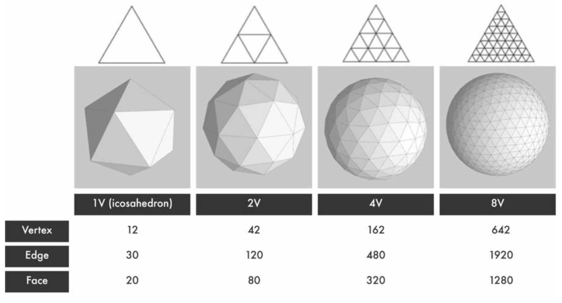
This section presents the concepts and design processes of a closed, surface-based SCD. SCDs controlled by actuator motions can express different shapes according to the actuation length and arrangement of the actuating pins. This process is explained in four key steps. First, a spherical model is tessellated considering the actuator positions required to simulate the shape deformation according to the arrangement and movement directions of the actuators. Second, a shape reconstruction optimization procedure for the closed, surface-based SCD is performed to ensure robust shape expressiveness. Finally, a physical SCD device is developed for real-time prototyping.

3.1. Tessellation

3D modeling and texture mapping on spherical displays are usually performed by substituting 2D rectangular plane coordinates with latitude and longitude values. However, the ability to express a certain shape depends on the density of the vertices that match the actuating pins on an SCD. It is necessary to arrange the actuators uniformly over the entire surface to construct various shapes. With conventional modeling methods, the density of the vertex increases as the number of poles of the spherical coordinate (latitude ± 90°) increases, and the physical size of the actuators causes interference between them. Therefore, an icosahedron-based icosphere model was used for the closed-surface SCD.
The icosphere achieves a high resolution by finely dividing the icosahedron surface. For example, the 2V icosphere is obtained by dividing all sides of the icosahedron into two. As shown in Figure 1, the nV icosphere has n2 triangles by dividing the sides of the icosahedron by n. As the resolution of the icosphere increases in a stepwise manner, the total number of vertices, edges, and faces increases exponentially. In this case, the number of faces for the nV resolution is n2 × 20, and the number of edges is n2 × 30. The relationship between the vertex and face to determine the number of vertices indicates five faces at 12 vertices, constituting the icosahedron, and six faces at the other vertices. Therefore, the number of vertices is ((number of faces) × 3 + 1)/6, that is, n2 × 10 + 2 in the nV resolution. This is equal to the number of actuating pins required to create an icosphere of the resolution in an SCD. In the SCD, an actuator is placed at each vertex, and the shape is deformed by pushing or pulling the surface in the radial direction of the surface (Figure 2).
We proposed the concept of dynamic range to standardize the degree of deformation. The dynamic range represented the ratio of the volume when the SCD was in the initial state (minimum size) to the volume of the fully actuated (maximum size) SCD. The volume ratio of the SCD was equal to the ratio of the cubed radius of the spherical guide structure, R , at each size; therefore, the equation for calculating the dynamic range is as follows:
D y n a m i c R a n g e = R + a c t u a t o r m a x H e i g h t 3 R + a c t u a t o r m i n H e i g h t 3
This type of actuator was used in the same environment with the same m o v i n g   d i s t a n c e , and the representation of the volume change could improve as the size decreased (Figure 3). Implementing smaller actuators could minimize the size of the SCD, whereas longer actuating pins could maximize the size, ultimately increasing the dynamic range. Assuming that (n2 × 10 + 2) actuators were attached to the spherical guide structure to achieve the target resolution of the nV icosphere, the size of the spherical guide structure could be calculated according to the actuator size (Figure 4). The total area required when (n2 × 10 + 2) circles were tightly arranged in a hexagonal form was 5 3   n 2 + 3   r 2 , where r is the radius of the actuator. The radius of the spherical guide structure, R , could be calculated as
R = 5 3 n 2 + 3 π r

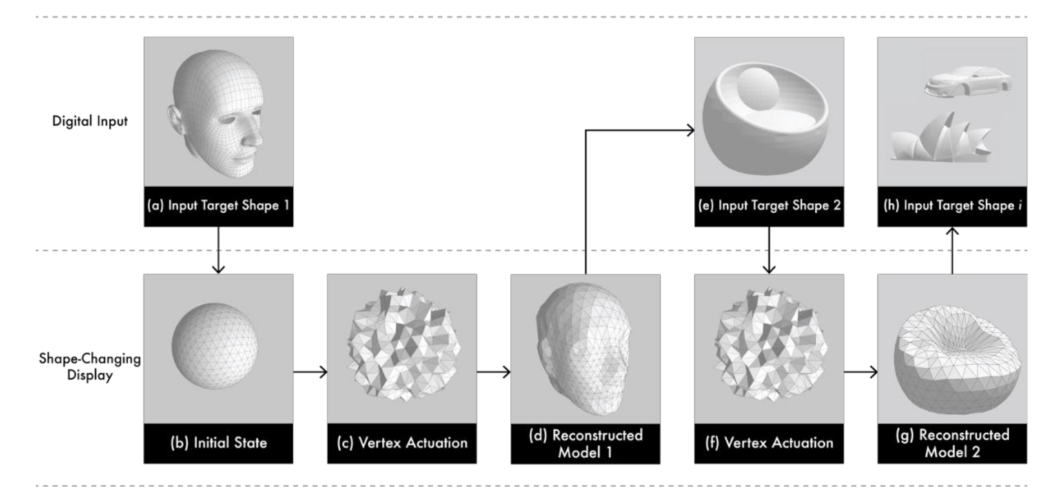
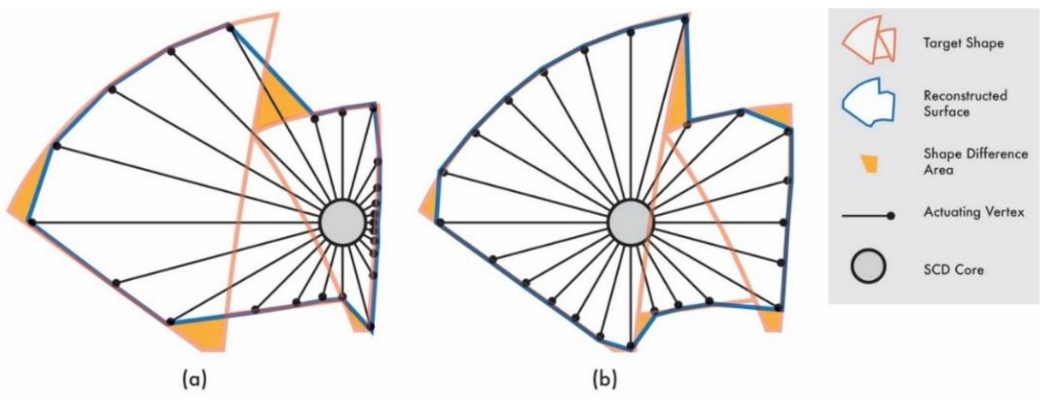
3.2. Shape Reconstruction and Optimization

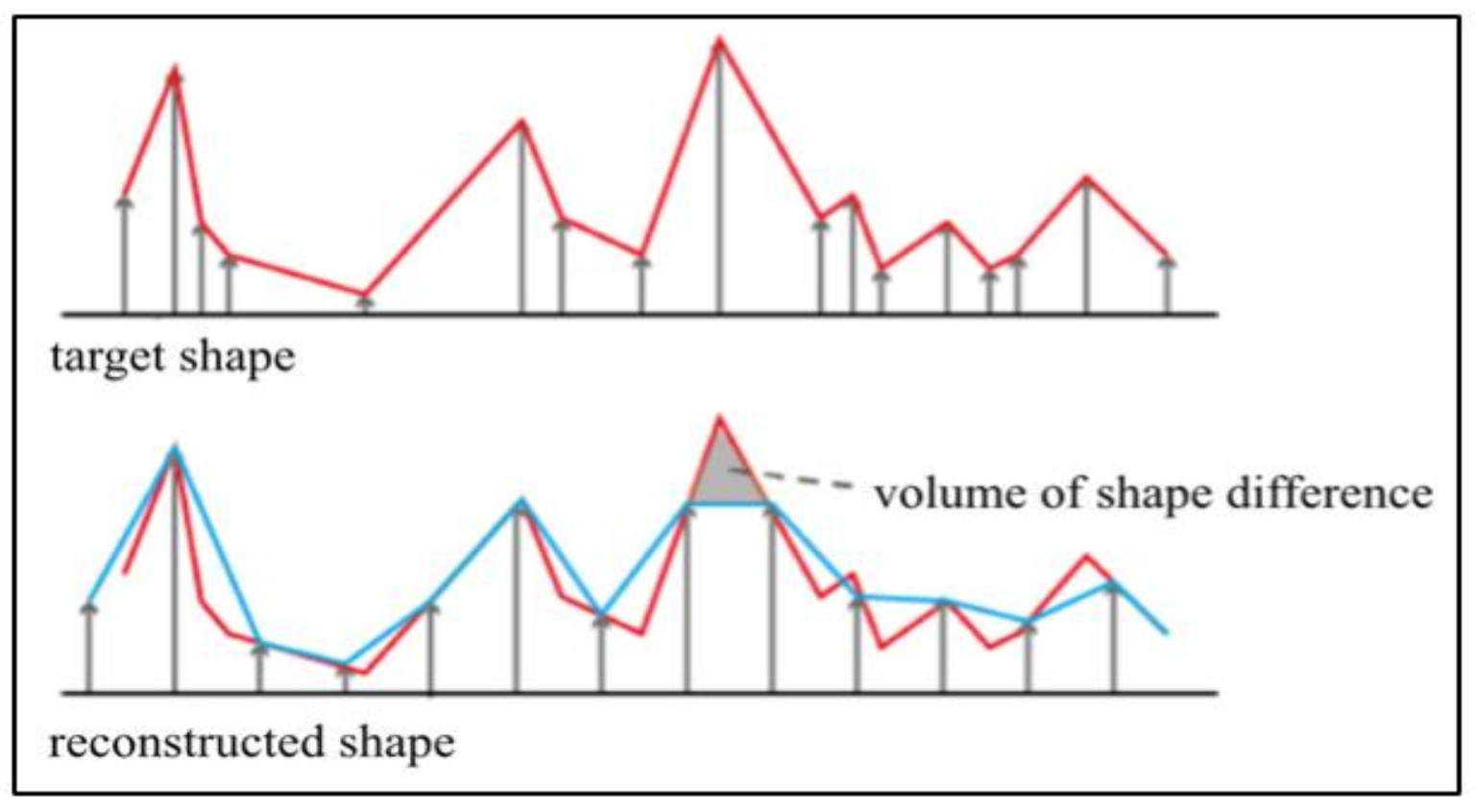
3.2.1. Shape Reconstruction and Evaluation

In the proposed SCD, it is necessary to calculate the length of each actuator in real time because their positions are fixed. This process adjusts the length of the fixed bars, as shown on the right side of Figure 4, to approximate the target shape. At this time, the target shape of the fixed bar is measured, and the length of the target shape is determined using information from the neighboring vertices. If we divide the area of one actuator into three dimensions, we can calculate the area, similar to the hexagons observed in the reconstructed shape in Figure 4, and determine the length of the actuator using the vertex value for this area. We also tested a method of using the mean of all vertices as the vertex information (Figure 4a) and the center-weight method of assigning higher weights to nearby vertices at the corresponding positions (Figure 4b). The center-weight is set to be proportional to the angle between the directions of the actuator and each vertex, from zero to the boundary of the hexagon.
The center-weight method was compared to the mean-value method (Figure 5). However, the mean-value model was found to be more uneven than the center-weight method model, and it was difficult to distinguish any notable difference.
To optimize shape reconstruction, the volume difference between the two models was measured to assess the similarity of the reconstructed model with the target shape. The symmetric difference between each model was calculated to compare the volume differences between the target and reconstructed models. For example, in the case of target models A and B, the value of volume (A-B) + volume (B-A) represents the shape difference. As shown in Figure 6, when the target model A (red line) is converted to the reconstructed model B (blue line) by adjusting the bar at a fixed position, a shape difference area (gray) is formed. These lines represent the surfaces of the 3D model, and the orange area denotes the volumetric shape difference.
The method of dividing the area is based on the shape corresponding to each side of the icosphere. In Figure 7a, the target shape and reconstructed shape are intersected using the constructive solid geometry technique. The two generated volumes are shown in Figure 7b, and the difference between the two models can be calculated from the sum of the absolute values of the differences in the volumes of the corresponding models. We proposed a method to optimize the center position of the reconstructed model to ensure that more complex bends can be represented in the model, or alternatively, more actuating pins can be placed in the parts that need to be expressed more precisely.

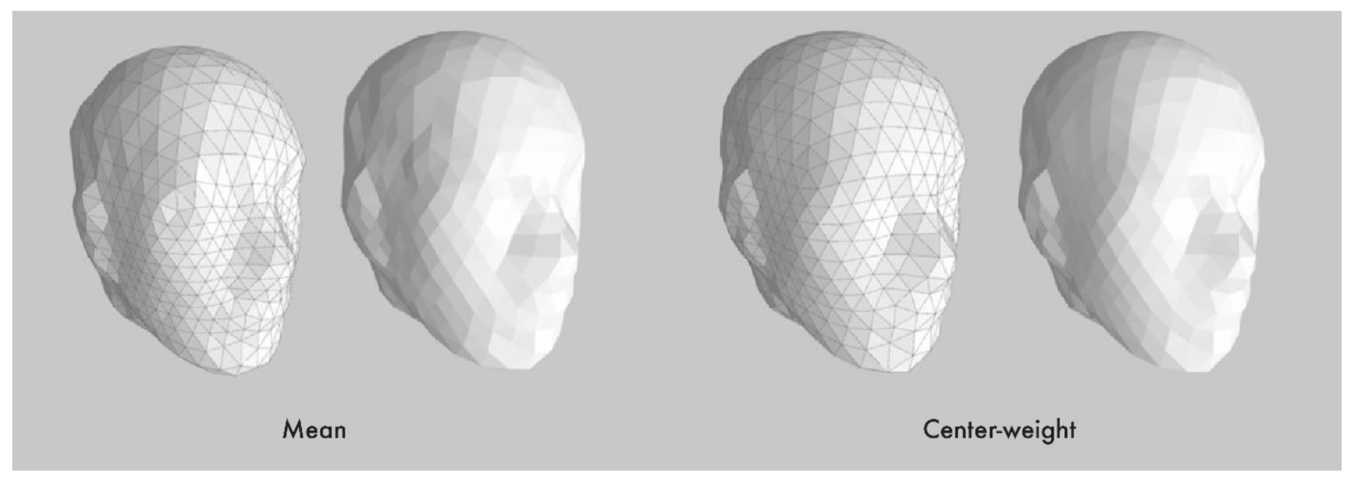
3.2.2. Actuator Center-Positioning Algorithm and Additional Weight

To optimize the position of the actuators, a measurement criterion needs to be defined. Considering the spherical model as an example, the normal vector of all surfaces has the same orientation as the direction vector from the center point to each surface, and it can form a near-perfect surface, assuming that the resolution of the icosphere can be increased infinitely. However, the larger the angle between the normal and direction vectors, the more difficult it is to maintain the resolution. For a surface with an angle greater than 90°, despite using a high-resolution icosphere model, the surface cannot be reconstructed. For example, the center point P (x, y, z) in Figure 8 has an angle greater than 90° with the normal vector (point behind the right ear). This demonstrates that the angle is difficult to express in the rear part of the ears, nose, and the vicinity of the mouth.
We set the expressive difficulty function for a specific face n consisting of three vectors (vn_1, vn_2, and vn_3) as Fn(x,y,z). More specifically, when the direction of v n 2 v n 1 × v n 3 v n 1 is away from the face (the expression direction), the nth face, v n 1 v n 2 v n 3 ¯ , can be expressed as follows:
C n c e n t e r o f m a s s = v n 1 + v n 2 + v n 3 3
F n x , y , z = w × A r e a o f f a c e × C n P ^ · n
The point P(x, y, z), where the sum of Fn(x,y,z) values of all the faces of the target shape is maximum, can be defined as the center position with the highest expressive quality. The weighting value, w, can be added to each face to determine the importance of the face when reconstructing the details while considering visual significance, such as assigning more weights on expressing the eyes and nose than the ears. We apply a gradient ascent algorithm to determine a local maximum value starting from the center of gravity of the target shape as a method to locate P, where the sum of Fn(x,y,z) becomes the maximum. The gradient function for a specific n-plane is given as follows:
F n x , y , z = F n x , F n y , F n z
F n x = v n 2 v n 1 × v n 3 v n 1 2 × n . x C P C P · n x C . x C P 3
F n y = v n 2 v n 1 × v n 3 v n 1 2 × n . y C P C P · n y C . y C P 3
F n z = v n 2 v n 1 × v n 3 v n 1 2 × n . z C P C P · n z C . z C P 3
The overall expressiveness function for P(x, y, z) can be defined as i = 1 n F i x , y , z , which is the sum of the gradient functions for all n faces. An optimized P(x, y, z) using the gradient descent algorithm can be obtained by repeating the following equation:
x k + 1 , y k + 1 , z k + 1 = x k , y k , z k + λ i = 1 n F i x k , y k , z k ,   k 0 ,   λ   i s   s t e p   s i z e
We also propose a method for weighing the specific features of a shape to better capture visually significant features. When comparing human faces, the nose and mouth can be more critical in recognizing the face than the ears. If there is an area of the SCD that requires a higher resolution, the weighting value w can be applied to the center-positioning equation. Figure 9 illustrates the three variations in the center positions and the respective results obtained using the 3D vase model. Considering the aforementioned shape difference, the number one center position that produces the most similar overall shape would be the best choice. However, if one desires to minimize the angles to the normal vector of each surface, considering the bent portion of the surface, the number two center position will be more suitable. Alternatively, if the angled base portion under the porcelain is important for the purpose, the number three center position would be the best option.

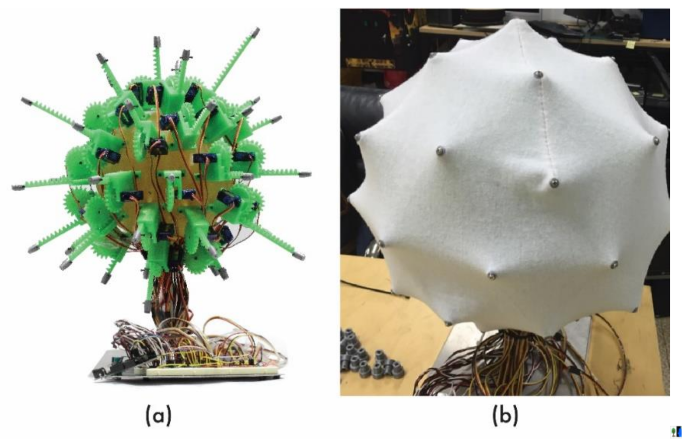
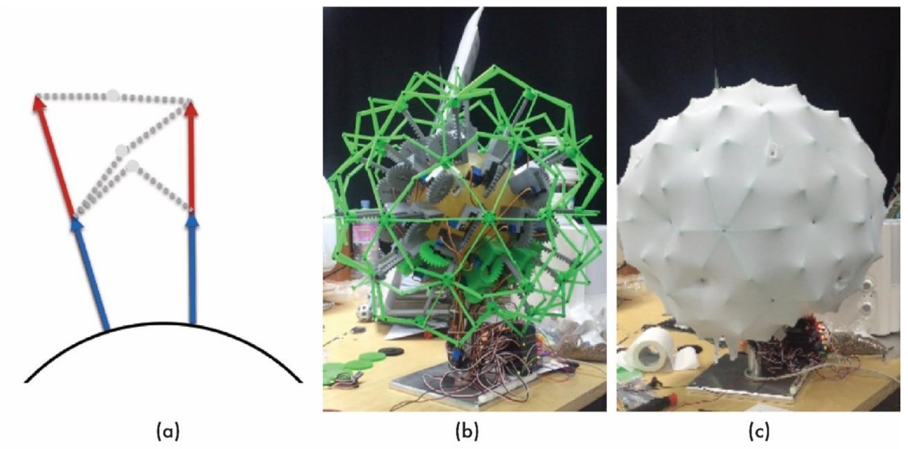
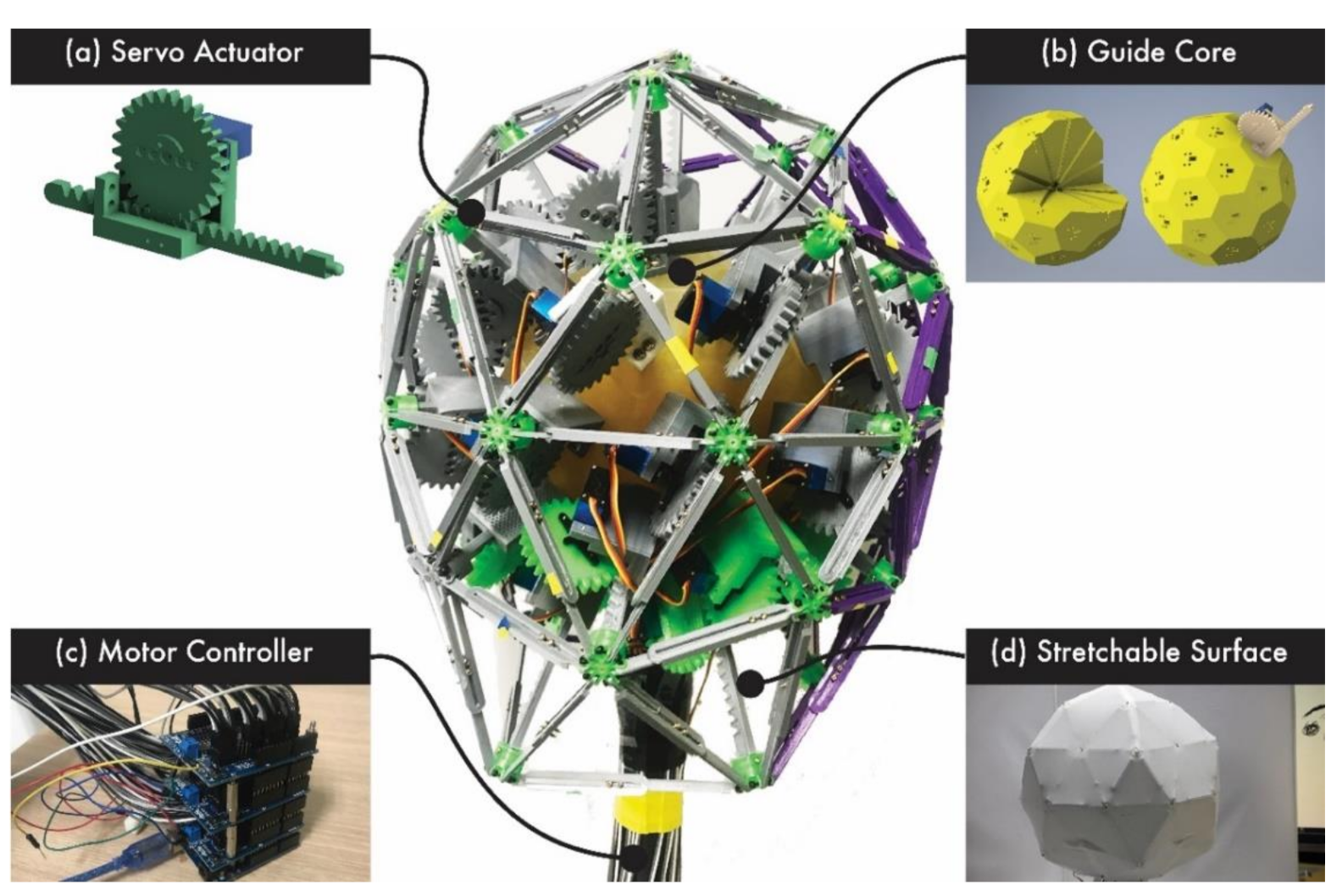
3.3. Shape-Changing Display Hardware Design

This section explains the design and development of SCD hardware to utilize tessellation, shape reconstruction, and optimization, as discussed above. Actuators were attached to each vertex point to create a dynamic SCD with a closed surface. The main points to be addressed in constructing this system are the core design parts that hold the positions and directions of the actuators and the surface design parts for handling the concave shape and wrinkles of the surface.

3.3.1. Guide Core Design

The design guide core of the SCD defines the arrangement of the actuating pins. The proposed SCD based on the spherical coordinate system deforms the shape by pushing and pulling the surface as the actuating points move linearly from the center point. We propose a core design in which the actuating pins are directly placed on the faces of the guide core. This design allows the actuators to be fixed at each vertex position based on the icosphere model. As shown in Figure 10a, a square hole and four screw holes are drilled at each vertex position based on the 2V icosphere model. The pins attached to the actuator were moved through the rectangular holes. The size of the core should be determined by considering the actuation distance, because the actuating pins may collide with the inside of the core (Figure 10b). Figure 10c shows the actuators attached to the core surface.

3.3.2. Surface Design

For a close-surfaced SCD in which the actuating pins are in a 3D arrangement and deformed along different directions, the distances between the actuating points are larger than the distances between the 2D tabletop SCDs. However, despite using a well-stretched screen material, the surface will have wrinkles depending on the direction of the forces it receives. The following three screening methods were considered to reduce the wrinkles caused by tension generated in the screen cloth: (1) pole-based surface, (2) scissor-hinge-based surface, and (3) cross-rod-based surface.
The pole-based surface method directly extrudes the linear actuator to the surface without requiring supporting structures (Figure 11). This method is simple, does not require any additional structures, and is relatively clean when the fabric is small. However, when the size of the fabric increases, under greater tension, the surface becomes concave. In addition, the high tension interferes with the actuators that extrude against the surface.
The scissor-hinge-based surface method (Figure 12) uses hinges that fold and unfold to maintain the tension of the fabric. In this method, the use of the tensile force of the cloth is limited; therefore, the screen does not droop, and the force applied to the actuator is small. Thus, the display operates in a more stable manner. However, owing to the hinge shape, the display always has a sharp surface, which limits the types of shapes that can be expressed by the SCD.
The cross-rod-based surface method (Figure 13) connects the end points of the actuating pins with cross-rod bridges to ensure that the screen does not curve concavely. Under this method, the surface of the SCD can be maintained as triangles that provide stable expressivity to the SCD. Additionally, the actuator damage and fabric wrinkles caused by tension are reduced. Therefore, the cross-rod bridges of the third method were applied to the internal structure of the SCD.

4. Results and Discussion

This section presents a detailed account of the design of the SCD system, including the hardware components and software developments, along with the results of the validation experiment conducted to test the robustness of the proposed system.

4.1. Shape-Changing Display Blueprint

We designed and built SCD hardware by utilizing the tessellation, shape reconstruction, and optimization discussed above. To test the idea of the proposed SCD being constructed and utilized, a 2V icosphere, the simplest close-surfaced SCD, with a high dynamic range was selected as the first working prototype.

4.1.1. Linear Actuating Pins

The proposed SCD used 41 actuating pins, comprising 41 MG90 servo motors. The MG90 model has a 0.25 kg/mm stall torque with a 6V icosphere, and each actuator in the system produces a force of 5.45 N. The SCD with 41 actuators presents an optimal dynamic range with market-available servo motors, owing to their sizes. The actuators must be controlled without impairing the shape of the topological sphere. Therefore, small-sized servo motors (21.5 × 11.8 × 22.7 mm) were used. Moreover, 45 mm-diameter spur gears, 100-mm rack gears, and other supporting parts were created using a 3D printer to manufacture 70-mm linear actuators with motors that could rotate at 180° (see Figure 14a).

4.1.2. Guide Core

The SCD is based on a geodesic spherical shape and is constructed such that each actuator can be arranged radially along the vertices of a 2V icosphere. To manufacture its components precisely, it is modeled using 3ds Max, as shown in Figure 14b, and the core (18 cm in diameter) is manufactured with a 3D printer (3D Systems—ProX800).

4.1.3. Motor Controller

To control the 41 servo actuators of the SCD, an open-source Arduino microcontroller board was used. An Arduino Uno model with an ATMega 328P-PU chip is used, and three Adafruit 16-channel pulse width modulation/servo shields are connected in parallel to control a maximum of 48 motors, as shown in Figure 14c. Depending on the pressure applied, the MG90 model consumes a maximum power of 5 W, which is supplied using a 300 W external power source.

4.1.4. Stretchable Surface

After assembling the hardware, the SCD was wrapped in a stretchable fabric to create a closed surface. The inter-vertex distance was approximately 1.5 times larger at the SCD’s maximum shape, in comparison to that at its minimum. Therefore, a highly elastic material that can easily stretch up to 150% of its original length while maintaining an appropriate tension is required. Moreover, a material with a cross-tape pattern was used to ensure that the direction of tension did not affect elasticity. In this implementation, a thin, white, two-way stretchable fabric consisting of 25% spandex and 75% nylon was used.

4.1.5. Discussion

The SCD hardware presented a fast response time and high dynamic range for use as a real-time prototyping tool. The SCD reconstructs digital objects into physical objects within seconds. The actuator can move a surface distance of 18–26 cm from the center of the guide core in 0.24 s. The SCD hardware with a 2V icosphere can expand its volume from 25 to 74 L. The SCD has advantages of the static form, as well as in dynamic motion representation. However, despite the fast response time and high dynamic range, the 2V icosphere-based SCD has limitations in reconstructing high-resolution shapes. Apparently, implementing a higher icosphere can significantly enhance the accuracy and resolution of the shapes reconstructed with the SCD. To test the quality of the shape reconstruction depending on the icosphere and center positioning, we conducted two validation experiments.

4.2. Validation Experiments

The validation experiments aimed to test the effectiveness of the proposed SCD for real-time prototyping. Two experiments were conducted to assess the capacity of the proposed system. The first experiment examined the resolution robustness depending on the nV icosahedrons. The second experiment tested the expressiveness of the different shape reconstruction methods.

4.2.1. Experiment 1: SCD Shape Difference Measurements

To test the SCD concept’s proof as a real-time physical prototyping tool, we tested the robustness of the 2V icosphere SCD in reconstructing a digital 3D model in a physical environment, and a shape-difference measurement comparison was conducted between the two. A comparison between the target shape and SCD with Lycra (Table 1) was performed to identify how the digital configuration of the SCD (number of actuating pins, their directions, and movable distances) could physically represent the target shape. An industrial 3D scanner (Artec Space Spider) was used to convert the shapes reconstructed by the physical SCD model. The scanner read the physical model at 7.5 fps with a point accuracy of 0.05 mm. The experimental results reveal that the SCD with Lycra accurately reconstructed the target shapes (Table 1: A = 0.06, B = 0.035, C = 0.144).

4.2.2. Experiment 2: Shape Resolution Robustness

In the first experiment, the resolution robustness, which depends on the nV icosahedron, was tested. The human head model was used in the experiment because it is known to be one of the most sophisticated shapes. We reconstructed the head model using four different types of icosahedrons (2V, 4V, 8V, and 16V icospheres). The 3D models used for the shape difference measurements were reconstructed using identical center-positioning methods. As illustrated in Table 2, the number of vertices significantly influences the resolution of the SCD at a particular level. The resolution of the SCD significantly improved as nV increased to 8V (shape difference compared to the ground truth: 2V = 0.592, 4V = 0.302, and 8V = 0.224). The SCD with the 16V icosphere had the highest resolution; however, its shape difference compared to the ground truth was not significantly different from that of 8V (0.173).
Based on the validation results of the resolution robustness, a higher nV icosahedron apparently leads to a more robust shape reconstruction with additional actuators. When considering the cost of the actuators, the 8V icosahedron (with 642 actuators) is more cost effective than the 16V icosahedron (with 2562 actuators). Thus, we conducted a second experiment to test the shape expressiveness of the SCD with the 8V icosphere, according to the various center-positioning methods.

4.2.3. Experiment 3: Shape Reconstruction Expressiveness

In the second experiment, seven objects were reconstructed with an 8V icosphere and compared to the ground truth digital models based on the shape difference calculation presented in Section 3.2. As shown in Table 3, the seven objects were reconstructed with the following five different center-positioning methods: (1) mean, (2) center-weight, (3–4) center positioning (fewer and more iterations), and (5) additional weight. The center-weight method appeared to afford sharp-pointed, high-resolution shapes, despite being viewed with the naked eye. To evaluate this more quantitatively, the shape difference for each model was calculated by dividing the volume difference with the target shape volume and displaying it below each reconstructed image. A negligible difference was observed between the models; however, the model reconstructed using the center-weight method had significantly fewer shape differences than those reconstructed using the mean-based 3D reconstruction method (paired t test: M = −0.042; t = −6.095; p < 0.001).

4.2.4. Discussion

The results of the center-positioning algorithm demonstrate that expressiveness can be changed by implementing visual significance. The visual significance of an object’s recognition can influence the expressiveness of the SCD. Better expressive quality can be achieved by providing visually significant features of the objects for additional weight-centering methods. For example, facial components, such as the nose, eyes, and lips, can be more significant expressors of the face than its overall shape. In this case, the proposed center-positioning algorithm moved the center points slightly closer to the visually significant features, using the method indicated in Section 3.2.2, to refine the density of the actuating vertices. As shown in Figure 15, the actuating vertex density on the surface varied depending on the location of the center position. The advantage of the dense actuating vertex is its robust SCD expressiveness of complicated surfaces, such as with the Sydney Opera House. By adding additional weights to the sail of the opera house, the center position changed and thus, the concave shape was better represented (Figure 15). In the face model presented in Table 3, the shapes of the nose and mouth in the additional weight results are clearer than those in the center-weight results. Because the center-positioning algorithm provides an optimization process for surface expressions, the shape difference can be increased. When the value of the model and the gradient function after the first iteration showing the largest change is sufficiently small (the maximum vertex length is 1/200), λ (step size) is 0.1, and all six models, except for the uneven cube, are created within 8–12 iterations. The bumpy cube model is symmetric; therefore, its position does not change, even when the center-positioning algorithm is rotated.
Here, as described in Section 4.1, a 2V icosphere SCD was implemented to demonstrate the practical feasibility and accuracy of 3D model reconstruction. We also confirmed the efficiency and effectiveness of the 8V-resolution SCD. To produce an 8V SCD, refer to Section 4.1.3; we redesigned the guide core to 8V, and an actuator appropriate for it was required. For an ideal 8V SCD design, an actuator with the smallest possible size had to be used. Using Maxon RE13, one of the currently available universal motors, it was possible to design an actuator with an attachment surface area of 900 mm2 or less by arranging the shaft axis in a radial direction (the motor took about 200 mm2). If the radius, r , of the actuator installation space was set at 17 mm using Equation (2), as proposed in Section 3.1, the radius of the smallest 8V SCD that could be manufactured would be approximately 226 mm. Considering the moving distance of the actuating pin, the approximate minimum and maximum diameters of the 8V SCD that could be manufactured were 600 and 1000 mm, respectively.

5. Conclusions

In this study, we introduced a closed, surface-based SCD for real-time prototyping. Accordingly, novel algorithms were developed to optimize shape reconstruction and to determine the ideal number and placement of the actuating pins to ensure a robust expression of shapes through the physical device. Validation experiments were conducted to identify the resolution robustness and shape reconstruction expressiveness displayed using the proposed SCD. The results demonstrated that the proposed method can accurately reconstruct an optimized shape. The simulations also revealed that complex organic shapes (rabbits and human faces) and man-made shapes (chairs, cars, and buildings) can be accurately reconstructed by using a closed, surface-based SCD with an optimized number of actuators. Although we used high-fidelity 3D digital models for the validation experiments, the proposed SCD can accommodate 3D models with various levels of detail.
The contribution of this study is two-fold. Academically, to the best of our knowledge, this is the first study on real-time prototyping using a closed, surface-based SCD that can accurately and instantly create physical reconstructions of digital 3D models. Unlike traditional tabletop SCDs, the proposed method requires solutions of various novel practical problems, such as 3D reconstruction optimization, platform architecture, surface tension, placement rules for actuators, new actuator designs, and interaction software. Our work contributes to the solutions of these problems by proposing a novel shape reconstruction algorithm that can be used even when the type and number of actuators are changed. Thus, we propose a complete component for designing a closed, surface-based SCD for real-time prototyping. The proposed method can be used as a foundation to aid the design prototyping process. The real-time shape changing quality of the SCD allows designers to immediately check a prototype from multiple viewpoints, thereby enabling them to communicate and provide more effective feedback.
Developing a more robust SCD requires further research. First, a novel actuator design that can expand the impact of SCDs is required. Currently, actuating pins are connected to gears that occupy a large volume. Thus, the minimization of these actuators can significantly improve the resolution of the display. Additionally, creating a modular SCD would improve the robustness of the 3D model expressions. For example, if we were to assemble more than one SCD, we could reconstruct more dynamic shapes with the display because there would be more than one actuation core. Second, if augmented reality with a head-mounted display was to be adopted for the SCD, the Lycra would not be required. Thus, users could better evaluate design concepts through real-time prototyping by touching and seeing the model. The proposed methods can be used in diverse industries, including architecture, product design, furniture design, and other fields that require 3D prototypes for design evaluations.

Author Contributions

Conceptualization, S.B. and K.H.H.; Data curation, Seonghoon Ban; Formal analysis, Seonghoon Ban; Funding acquisition, K.H.H.; Investigation, Seonghoon Ban; Methodology, S.B. and K.H.H.; Project administration, K.H.H.; Resources, K.H.H.; Software, Seonghoon Ban; Supervision, K.H.H.; Validation, S.B. and K.H.H.; Visualization, S.B. and K.H.H.; Writing—original draft, S.B. and K.H.H.; Writing—review & editing, S.B. and K.H.H. All authors have read and agreed to the published version of the manuscript.

Funding

This work was supported by a National Research Foundation of Korea (NRF) grant funded by the Korean government (MSIP: Ministry of Science, ICT and Future Planning) (NRF-2020R1C1C1011974).

Institutional Review Board Statement

Not applicable.

Informed Consent Statement

Not applicable.

Data Availability Statement

No data.

Conflicts of Interest

The authors declare no conflict of interest.

References

  1. Deininger, M.; Daly, S.R.; Sienko, K.H.; Lee, J.C. Novice designers’ use of prototypes in engineering design. Des. Stud. 2017, 51, 25–65. [Google Scholar] [CrossRef] [PubMed]
  2. Kelley, T.A. The Art of Innovation: Lessons in Creativity from IDEO, America’s Leading Design Firm; Broadway Business: New York, NY, USA, 2001; Volume 10. [Google Scholar]
  3. Goyale, R. Why Is Prototyping Important? Available online: https://blog.zipboard.co/why-is-prototyping-important-13150d76abc4 (accessed on 2 April 2019).
  4. Stappers, P.J.; van Rijn, H.; Kistemaker, S.C.; Hennink, A.E.; Sleeswijk Visser, F.S. Designing for other people’s strengths and motivations: Three cases using context, visions, and experiential prototypes. Adv. Eng. Inform. 2009, 23, 174–183. [Google Scholar] [CrossRef]
  5. Yuan, X.; Lee, J.-H. A quantitative approach for assessment of creativity in product design. Adv. Eng. Inform. 2014, 28, 528–541. [Google Scholar] [CrossRef]
  6. Schrage, M. Cultures of Prototyping. Bringing Design to Software; ACM Press: New York, NY, USA, 1996; pp. 191–205. [Google Scholar] [CrossRef]
  7. Camburn, B.; Viswanathan, V.; Linsey, J.; Anderson, D.; Jensen, D.; Crawford, R.; Otto, K.; Wood, K. Design prototyping methods: State of the art in strategies, techniques, and guidelines. Des. Sci. 2017, 3, 3. [Google Scholar] [CrossRef] [Green Version]
  8. Arrighi, P.-A.; Mougenot, C. Towards user empowerment in product design: A mixed reality tool for interactive virtual prototyping. J. Intell. Manuf. 2019, 30, 743–754. [Google Scholar] [CrossRef]
  9. Borsci, S.; Lawson, G.; Broome, S. Empirical evidence, evaluation criteria and challenges for the effectiveness of virtual and mixed reality tools for training operators of car service maintenance. Comput. Ind. 2015, 67, 17–26. [Google Scholar] [CrossRef]
  10. Zheng, P.; Xu, X.; Chen, C.-H. A data-driven cyber-physical approach for personalised smart, connected product co-development in a cloud-based environment. J. Intell. Manuf. 2020, 31, 3–18. [Google Scholar] [CrossRef]
  11. Ferrise, F.; Graziosi, S.; Bordegoni, M. Prototyping strategies for multisensory product experience engineering. J. Intell. Manuf. 2017, 28, 1695–1707. [Google Scholar] [CrossRef]
  12. Bund, S.; Do, E.Y.-L. SPOT! Fetch Light: Interactive navigable 3D visualization of direct sunlight. Autom. Constr. 2005, 14, 181–188. [Google Scholar] [CrossRef]
  13. Lovreglio, R.; Gonzalez, V.; Feng, Z.; Amor, R.; Spearpoint, M.; Thomas, J.; Trotter, M.; Sacks, R. Prototyping virtual reality serious games for building earthquake preparedness: The Auckland City Hospital case study. Adv. Eng. Inform. 2018, 38, 670–682. [Google Scholar] [CrossRef] [Green Version]
  14. Shen, Q.; Gausemeier, J.; Bauch, J.; Radkowski, R. A cooperative virtual prototyping system for mechatronic solution elements based assembly. Adv. Eng. Inform. 2005, 19, 169–177. [Google Scholar] [CrossRef]
  15. Shen, Q.; Grafe, M. To support multidisciplinary communication in VR-based virtual prototyping of mechatronic systems. Adv. Eng. Inform. 2007, 21, 201–209. [Google Scholar] [CrossRef]
  16. Thomas, P.; David, W. Augmented Reality: An Application of Heads-Up Display Technology to Manual Manufacturing Processes. In Proceedings of the 25th Hawaii International Conference on System Sciences, Kauai, HI, USA, 7–10 January 1992; pp. 659–669. [Google Scholar]
  17. Milgram, P.; Kishino, F. A taxonomy of mixed reality visual displays. I.E.I.C.E. Trans. Inf. Syst. 1994, 77, 1321–1329. [Google Scholar]
  18. Johnson, S.; Gibson, M.; Mutlu, B. Handheld or Handsfree? Remote Collaboration via Lightweight Head-Mounted Displays and Handheld Devices. In Proceedings of the 18th A.C.M. Conference on Computer Supported Cooperative Work & Social Computing, Vancouver, BC, Canada, 14–18 March 2015; pp. 1825–1836. [Google Scholar]
  19. Benko, H.; Holz, C.; Sinclair, M.J.; Ofek, E. Normaltouch and texturetouch: High-fidelity 3D haptic shape rendering on handheld virtual reality controllers. In Proceedings of the 29th Annual Symposium on User Interface Software and Technology, Tokyo, Japan, 16–19 October 2016. [Google Scholar]
  20. Suzuki, Y.; Kobayash, M. Air jet driven force feedback in virtual reality. IEEE Comput. Graph. Appl. 2005, 25, 44–47. [Google Scholar] [CrossRef]
  21. Shigeyama, J.; Hashioto, T.; Yoshida, S.; Aoki, T.; Narumi, T.; Tanikawa, T.; Hirose, M. Transcalibur: Weight moving VR controller for dynamic rendering of 2D shape using haptic shape illusion. In Proceedings of the ACM SIGGRAPH 2018 Emerging Technologies, Vancouver, BC, Canada, 12–16 August 2018. [Google Scholar]
  22. Maimani, A.A.; Roudaut, A. Frozen suit: Toward a changeable stiffness suit and its application for haptic games. In Proceedings of the CHI Conference on Human Factors in Computing Systems, Denver, CO, USA, 6–11 May 2017. [Google Scholar]
  23. Kim, H.; Yi, H.B.; Lee, H.; Lee, W. HapCube: A Wearable Tactile Device to Provide Tangential and Normal Pseudo-Force Feedback on a Fingertip. In Proceedings of the CHI Conference on Human Factors in Computing Systems, Montreal, QC, Canada, 21–26 April 2018. [Google Scholar]
  24. Gu, N.; Kim, M.J.; Maher, M.L. Technological advancements in synchronous collaboration: The effect of 3D virtual worlds and tangible user interfaces on architectural design. Autom. Constr. 2011, 20, 270–278. [Google Scholar] [CrossRef]
  25. Nasman, J.; Cutler, B. Evaluation of user interaction with daylighting simulation in a tangible user interface. Autom. Constr. 2013, 36, 117–127. [Google Scholar] [CrossRef]
  26. Siu, A.F.; Yuan, S.; Pham, H.; Gonzalez, E.; Kim, L.H.; Le Goc, M.; Follmer, S. Investigating Tangible Collaboration for Design. Towards Augmented Physical Telepresence. In Design Thinking Research; Springer: Cham, Switzerland, 2018; pp. 131–145. [Google Scholar]
  27. Berni, A.; Maccioni, L.; Borgianni, Y. Observing pictures and videos of creative products: An eye tracking study. Appl. Sci. 2020, 10, 1480. [Google Scholar] [CrossRef] [Green Version]
  28. Neeley, W.L.; Lim, K.; Zhu, A.; Yang, M.C. Building fast to think faster: Exploiting rapid prototyping to accelerate ideation during early stage design. In Proceedings of the ASME 2013 International Design Engineering Technical Conferences and Computers and Information in Engineering Conference, Portland, OR, USA, 4–7 August 2013. [Google Scholar]
  29. He, K.; Zhang, Q.; Hong, Y. Profile monitoring based quality control method for fused deposition modeling process. J. Intell. Manuf. 2019, 30, 947–958. [Google Scholar] [CrossRef] [Green Version]
  30. Rosso, S.; Uriati, F.; Grigolato, L.; Meneghello, R.; Concheri, G.; Savio, G. An optimization workflow in design for additive manufacturing. Appl. Sci. 2021, 11, 2572. [Google Scholar] [CrossRef]
  31. Georgiev, G.V.; Taura, T. Using idea materialization to enhance design creativity. In Proceedings of the 20th International Conference on Engineering Design (ICED 15), Milan, Italy, 27–30 July 2015; pp. 349–358. [Google Scholar]
  32. Gonçalves, M.; Cardoso, C.; Badke-Schaub, P. What inspires designers? Preferences on inspirational approaches during idea generation. Des. Stud. 2014, 35, 29–53. [Google Scholar] [CrossRef]
  33. Viswanathan, V.K.; Linsey, J.S. Role of sunk cost in engineering idea generation: An experimental investigation. J. Mecha. Des. 2013, 135, 121002. [Google Scholar] [CrossRef]
  34. Mueller, S.; Mohr, T.; Guenther, K.; Frohnhofen, J.; Baudisch, P. faBrickation: Fast 3D printing of functional objects by integrating construction kit building blocks. In Proceedings of the SIGCHI Conference on Human Factors in Computing Systems, Toronto, Canada, 26 April–1 May 2014; pp. 3827–3834. [Google Scholar]
  35. Kohtala, S.; Steinert, M. From Hand-Drawn Sketching to Laser Cutting-A Proof of Concept Prototype and Pilot Study. In Proceedings of the Design Society. International Conference on Engineering Design, Delft, The Netherlands, 5–8 August 2019; pp. 339–348. [Google Scholar]
  36. Iwata, H.; Yano, H.; Nakaizumi, F.; Kawamura, R. Project FEELEX: Adding Haptic Surface to Graphics. In Proceedings of the 28th Annual Conference on Computer Graphics and Interactive Techniques, Los Angeles, CA, USA, 12-17 August 2001; pp. 469–476. [Google Scholar]
  37. Follmer, S.; Leithinger, D.; Olwal, A.; Hogge, A.; Ishii, H. InFORM: Dynamic Physical Affordances and Constraints through Shape and Object Actuation. In Proceedings of the 26th Annual ACM Symposium on User Interface Software and Technology, St. Andrews, Scotland, UK, 8–11 October 2013; pp. 417–426. [Google Scholar]
  38. Leithinger, D.; Ishii, H. Relief: A Scalable Actuated Shape Display. In Proceedings of the Fourth International Conference on Tangible, Embedded, and Embodied Interaction, Cambridge, MA, USA, 25–27 January 2010; pp. 221–222. [Google Scholar]
  39. Lim, Y.-K.; Stolterman, E.; Tenenberg, J. The anatomy of prototypes: Prototypes as filters, prototypes as manifestations of design ideas. ACM Trans. Comput. Hum. Interact. 2008, 15, 1–27. [Google Scholar] [CrossRef]
  40. Rayna, T.; Striukova, L. From rapid prototyping to home fabrication: How 3D printing is changing business model innovation. Technol. Forecast. Soc. Chang. 2016, 102, 214–224. [Google Scholar] [CrossRef] [Green Version]
  41. Thomke, S. Managing digital design at BMW. Des. Manag. J. 2001, 12, 20–28. [Google Scholar] [CrossRef]
  42. Gupta, R.; Whitney, D.; Zeltzer, D. Prototyping and design for assembly analysis using multimodal virtual environments. Comput. Aid. Des. 1997, 29, 585–597. [Google Scholar] [CrossRef] [Green Version]
  43. Kim, H.-J.; Kim, J.-W.; Nam, T.-J. miniStudio: Designers’ Tool for Prototyping Ubicomp Space with Interactive Miniature. In Proceedings of the 2016 Chi Conference on Human Factors in Computing Systems, San Jose, CA, USA, 7–12 May 2016; pp. 213–224. [Google Scholar]
  44. Seth, A.; Su, H.-J.; Vance, J.M. SHARP: A System for Haptic Assembly and Realistic Prototyping. In Proceedings of the ASME 2006 International Design Engineering Technical Conferences and Computers and Information in Engineering Conference, Philadelphia, PA, USA, 10–13 September 2006; pp. 905–912. [Google Scholar]
  45. Ban, S.; Hyun, K.H. Directional force feedback: Mechanical force concentration for immersive experience in virtual reality. Appl. Sci. 2019, 9, 3692. [Google Scholar] [CrossRef] [Green Version]
  46. Son, K.; Chun, H.; Park, S.; Hyun, K.H. C-Space: An Interactive Prototyping Platform for Collaborative Spatial Design Exploration. In Proceedings of the 2020 CHI Conference on Human Factors in Computing Systems, Honolulu, HI, USA, 25–30 April 2020; pp. 1–13. [Google Scholar]
  47. Park, H.; Moon, H.-C.; Lee, J.Y. Tangible augmented prototyping of digital handheld products. Comput. Ind. 2009, 60, 114–125. [Google Scholar] [CrossRef]
  48. Barbieri, L.; Angilica, A.; Bruno, F.; Muzzupappa, M. Mixed prototyping with configurable physical archetype for usability evaluation of product interfaces. Comput. Ind. 2013, 64, 310–323. [Google Scholar] [CrossRef]
  49. Li, J.; Weng, J.; Xu, H.; Zhou, C.; Zhang, D.; Lu, G. Design of robotic mannequin formed by flexible belt nett. Comput. Aid. Des. 2019, 110, 1–10. [Google Scholar] [CrossRef]
  50. Everitt, A.; Taher, F.; Alexander, J. ShapeCanvas: An Exploration of Shape-Changing Content Generation by Members of the Public. In Proceedings of the 2016 Chi Conference on Human Factors in Computing Systems, San Jose, CA, USA, 7–12 May 2016; pp. 2778–2782. [Google Scholar]
  51. Hemmert, F.; Hamann, S.; Löwe, M.; Zeipelt, J.; Joost, G. Shape-Changing Mobiles: Tapering in Two-Dimensional Deformational Displays in Mobile Phones. In Proceedings of the CHI’10 Extended Abstracts of the on Human Factors in Computing Systems, Atlanta, GA, USA, 10–15 April 2010; pp. 3075–3080. [Google Scholar]
  52. Kim, S.; Kim, H.; Lee, B.; Nam, T.-J.; Lee, W. Inflatable Mouse: Volume-Adjustable Mouse with Air-Pressure-Sensitive Input and Haptic Feedback. In Proceedings of the S.I.G.C.H.I. Conference on Human Factors in Computing Systems, Florence, Italy, 5–10 April 2008; pp. 211–224. [Google Scholar]
  53. Ramsgard Thomsen, M. Textile Logics in a Moving Architecture. In Proceedings of the Transitive Materials Workshop, CHI 2009 Workshop, Boston, MA, USA, 4–9 April 2009. [Google Scholar]
  54. Togler, J.; Hemmert, F.; Wettach, R. Living Interfaces: The Thrifty Faucet. In Proceedings of the 3rd International Conference on Tangible and Embedded Interaction, Cambridge, UK, 16–18 February 2009; pp. 43–44. [Google Scholar]
  55. Bau, O.; Petrevski, U.; Mackay, W. Bubble Wrap: A Textile-Based Electromagnetic Haptic Display. In Proceedings of the CHI’09 Extended Abstracts of the on Human Factors in Computing Systems, Boston, MA, USA, 4–9 April 2009; pp. 3607–3612. [Google Scholar]
  56. Kammermeier, P.; Buss, M.; Schmidt, G. Dynamic Display of Distributed Tactile Shape Information by a Prototypical Actuator Array. In Proceedings of the IEEE Publications/RSJ International Conference on Intelligent Robots and Systems (IROS 2000) (Cat. No. 00CH37113), Takamatsu, Japan, 31 October–5 November 2000; Volume 2000, pp. 1119–1124. [Google Scholar]
  57. Poupyrev, I.; Nashida, T.; Okabe, M. Actuation and Tangible User Interfaces: The Vaucanson Duck, Robots, and Shape Displays. In Proceedings of the 1st International Conference on Tangible and Embedded Interaction, Baton Rouge, LA, USA, 15–17 February 2007; pp. 205–212. [Google Scholar]
  58. Coelho, M.; Zigelbaum, J. Shape-changing interfaces. Pers. Ubiquitous Comput. 2011, 15, 161–173. [Google Scholar] [CrossRef]
  59. Rasmussen, M.K.; Pedersen, E.W.; Petersen, M.G.; Hornbæk, K. Shape-Changing Interfaces: A Review of the Design Space and Open Research Questions. In Proceedings of the SIGCHI Conference on Human Factors in Computing Systems, Austin, TX, USA, 5–10 May 2012; pp. 735–744. [Google Scholar]
  60. Cruz-Neira, C.; Sandin, D.J.; DeFanti, T.A. Surround-Screen Projection-Based Virtual Reality: The Design and Implementation of the CAVE. In Proceedings of the 20th Annual Conference on Computer Graphics and Interactive Techniques, Anaheim, CA, USA, 1–6 August 1993; pp. 135–142. [Google Scholar]
  61. Haeusler, M. Media Facades-History, Technology, Content. 2009. Available online: http://hdl.handle.net/10453/12401 (accessed on 2 April 2019).
  62. Narita, G.; Watanabe, Y.; Ishikawa, M. Dynamic projection mapping onto deforming non-rigid surface using deformable dot cluster marker. IEEE Trans. Vis. Comput. Graph. 2017, 23, 1235–1248. [Google Scholar] [CrossRef]
  63. Roo, J.S.; Gervais, R.; Hachet, M. Inner Garden: An Augmented Sandbox Designed for Self-Reflection. In Proceedings of the TEI’16: Tenth International Conference on Tangible, Embedded, and Embodied Interaction, Eindhoven, The Netherlands, 14–17 February 2016; pp. 570–576. [Google Scholar]
  64. Bruno, F.; Bruno, S.; De Sensi, G.; Luchi, M.-L.; Mancuso, S.; Muzzupappa, M. From 3D reconstruction to virtual reality: A complete methodology for digital archaeological exhibition. J. Cult. Herit. 2010, 11, 42–49. [Google Scholar] [CrossRef]
  65. Dalsgaard, P.; Halskov, K. 3D Projection on Physical Objects: Design Insights from Five Real Life Cases. In Proceedings of the S.I.G.C.H.I. Conference on Human Factors in Computing Systems, Vancouver, BC, Canada, 7–12 May 2011; pp. 1041–1050. [Google Scholar]
  66. Jang, S.; Kim, L.H.; Tanner, K.; Ishii, H.; Follmer, S. Haptic Edge Display for Mobile Tactile Interaction. In Proceedings of the 2016 Chi Conference on Human Factors in Computing Systems, San Jose, CA, USA, 7–12 May 2016; pp. 3706–3716. [Google Scholar]
  67. Hardy, J.; Weichel, C.; Taher, F.; Vidler, J.; Alexander, J. Shapeclip: Towards Rapid Prototyping with Shape-Changing Displays for Designers. In Proceedings of the 33rd Annual A.C.M. Conference on Human Factors in Computing Systems, Seoul, Korea, 18–23 April 2015; pp. 19–28. [Google Scholar]
Figure 1. Number of vertices, edges, and faces according to the resolution of the icosphere.
Applsci 11 04181 g001
Figure 2. Example of transforming a shape by adjusting the vertex value in the icosphere model: (a) inputting the target shape, (b) setting the icosphere model, (c) actuating each vertex, (d) reconstructing it in the form of the target, and (eh) iterated reconstruction of the new target shapes.
Applsci 11 04181 g002
Figure 3. Assuming that the actuating pins have hexagonal packing, the dynamic range, that is, the rate of change of the total volume, can be calculated. (a) Example of hexagonal packing by calculating the range of influence of the actuating pins, depicted in circles; (b) boundary line (actuator_minHeight) at the minimum size, and the boundary line (actuator_maxHeight) at the maximum size.
Applsci 11 04181 g003
Figure 4. Process of arranging vertices according to the position of the limited actuating pins.
Applsci 11 04181 g004
Figure 5. Approach for calculating the length of each actuating pin. The reconstructed model using the mean values of surrounding vertices is shown on the left, and the reconstructed model obtained by setting the weight proportional to the distance of the surrounding vertex value is shown on the right.
Applsci 11 04181 g005
Figure 6. Shape difference between the target shape and reconstructed shape, used as a criterion to estimate the quality of result.
Applsci 11 04181 g006
Figure 7. In the area corresponding to one side of the icosphere, (a) the difference in volume can be calculated by creating an intersection such as (b) that of the target shape (red) and the reconstructed shape (blue).
Applsci 11 04181 g007
Figure 8. (a) Model visualizing the angle (0 to 180°) with respect to the target shape plane at a specific point P (x, y, z) with color variations (blue to red). (b) Calculation of the expressiveness function (F) for one face.
Applsci 11 04181 g008
Figure 9. Example of resultant differences according to the center position. Depending on the surface at which the visual significance feature is located, the center position is changed by assigning an additional weight to the surface.
Applsci 11 04181 g009
Figure 10. Design of a core that attaches the actuators directly on the surface; guide core (a), sectional view (b), and guide core with actuators (c).
Applsci 11 04181 g010
Figure 11. Lycra screen placed over the poles of radially arranged actuating pins to form a screen: (a) internal hardware and (b) formation of concave shapes due to tension in the screen surface.
Applsci 11 04181 g011
Figure 12. Approach to connect the tip of each actuator to a scissor-hinge to maintain the distance between actuating pins: (a) working concept of the scissor-hinge (gray), (b) internal structure with scissor-hinge, and (c) with the Lycra screen.
Applsci 11 04181 g012
Figure 13. Design with cross-rod that prevents the curvature of the screen by maintaining a straight line between actuating pins: (a) concept of driving a cross-rod bridge (gray), (b) internal structure with the cross-rod bridge, and (c) with Lycra screen.
Applsci 11 04181 g013
Figure 14. Hardware components: (a) servo actuator, (b) guide core, (c) motor controller, and (d) stretchable surface.
Applsci 11 04181 g014
Figure 15. Comparison of actuating vertex density of the Sydney Opera House constructed using two different center positions (a,b).
Applsci 11 04181 g015
Table 1. Resolution of SCD depending on the nV Icosahedron.
(A)(B)(C)
Target Shapes Applsci 11 04181 i001 Applsci 11 04181 i002 Applsci 11 04181 i003
3D-Scanned SCD Constructing the Target Shape Applsci 11 04181 i004 Applsci 11 04181 i005 Applsci 11 04181 i006
Shape Difference Value0.0600.0350.144
Table 2. Resolution of SCD depending on the nV Icosahedron.
Right-Quarter ViewFront ViewLeft-Quarter View
Ground Truth Applsci 11 04181 i007 Applsci 11 04181 i008 Applsci 11 04181 i009
2V Icosphere
Vertex: 42
Edge: 120
Face: 80
Shape Difference = 0.592
Applsci 11 04181 i010 Applsci 11 04181 i011 Applsci 11 04181 i012
4V Icosphere
Vertex: 162
Edge: 480
Face: 320
Shape Difference = 0.302
Applsci 11 04181 i013 Applsci 11 04181 i014 Applsci 11 04181 i015
8V Icosphere
Vertex: 642
Edge: 1920
Face: 1280
Shape Difference = 0.224
Applsci 11 04181 i016 Applsci 11 04181 i017 Applsci 11 04181 i018
16V Icosphere
Vertex: 2562
Edge: 7680
Face: 5120
Shape Difference = 0.173
Applsci 11 04181 i019 Applsci 11 04181 i020 Applsci 11 04181 i021
Table 3. Reconstruction and evaluation of target shapes depending on different shape reconstruction methods.
Ground TruthMeanCenter-WeightCenter
Positioning
(Fewer Iterations)
Center
Positioning
(More Iterations)
Additional
Weight
Applsci 11 04181 i022 Applsci 11 04181 i023 Applsci 11 04181 i024
Bumpy Cube
Shape Difference
(1/original volume)
0.0650.035
Applsci 11 04181 i025 Applsci 11 04181 i026 Applsci 11 04181 i027 Applsci 11 04181 i028 Applsci 11 04181 i029 Applsci 11 04181 i030
Rabbit0.1500.1050.1110.1180.107
Applsci 11 04181 i031 Applsci 11 04181 i032 Applsci 11 04181 i033 Applsci 11 04181 i034 Applsci 11 04181 i035 Applsci 11 04181 i036
Cow0.2190.1470.1480.1580.151
Applsci 11 04181 i037 Applsci 11 04181 i038 Applsci 11 04181 i039 Applsci 11 04181 i040 Applsci 11 04181 i041 Applsci 11 04181 i042
Face0.0570.0380.0360.0360.052
Applsci 11 04181 i043 Applsci 11 04181 i044 Applsci 11 04181 i045 Applsci 11 04181 i046 Applsci 11 04181 i047 Applsci 11 04181 i048
Chair0.0830.0570.0780.0760.054
Applsci 11 04181 i049 Applsci 11 04181 i050 Applsci 11 04181 i051 Applsci 11 04181 i052 Applsci 11 04181 i053 Applsci 11 04181 i054
Car0.1400.0920.0910.0910.091
Applsci 11 04181 i055 Applsci 11 04181 i056 Applsci 11 04181 i057 Applsci 11 04181 i058 Applsci 11 04181 i059 Applsci 11 04181 i060
Building0.1610.1100.1100.1100.110
Publisher’s Note: MDPI stays neutral with regard to jurisdictional claims in published maps and institutional affiliations.

