Determination of Methodology and Research of the Influence of the Trial Run of High-Precision Reducers on the Change of Their Characterizing Properties
Abstract
1. Introduction
- Planetary mechanism—reducers with involute gearing.
- Cycloidal mechanism—reducers with trochoidal gearing.
- Harmonic mechanism—reducers with involute gearing.
- Spinea—Slovak manufacturer of high-precision compact bearing reducers TwinSpin. Their global market share is about 3.3%.
- Nabtesco—Japanese manufacturer of high precision reducers. Their share of the precision compact reducers market is 47%.
- Sumitomo Cyklo—Japanese manufacturer of precision reducers. Their global market share for precision gearboxes is 11.7%.
- Harmonic Drive—Japanese manufacturer of precision reducers. This company uses harmonic transmission in their gearboxes. Their share of the precision compact reducers market is 37.5%.
- Other manufacturers of precision gearboxes with various transformer members share about 0.5% of the world market [19].
2. Parameters Characteristic of High-Precision Reducers
2.1. Backlash (Backlash in Teeth)
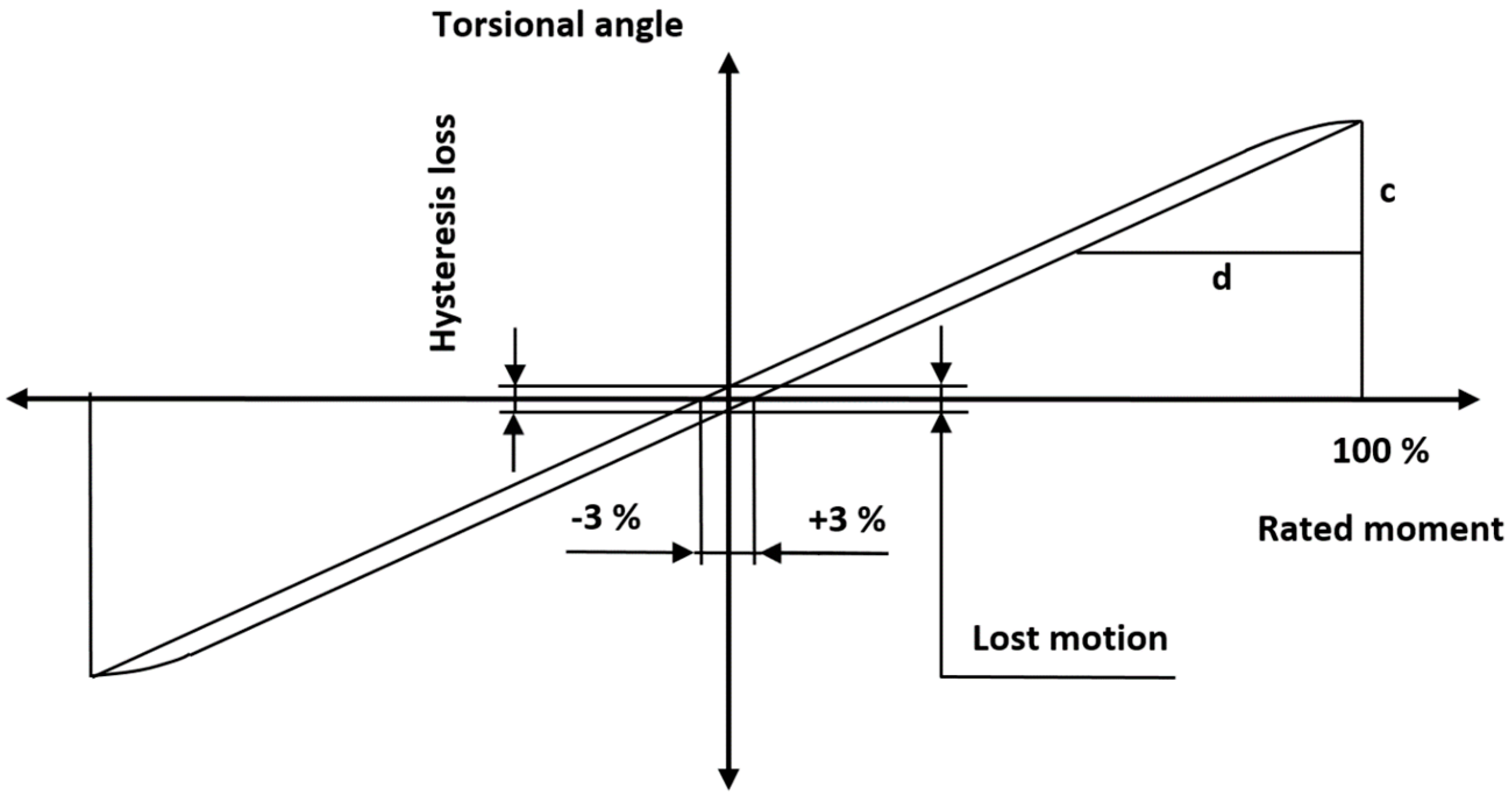
2.2. Hysteresis
2.3. Angular Transmission Error
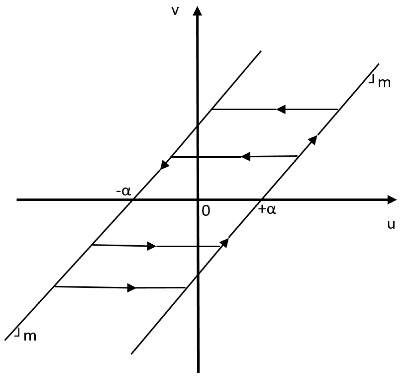
2.4. Dead Zone
2.5. Other Parameters Characteristic of High-Precision Reducers
- Starting torque—a load-free, quasi-static torque is required to start the rotation of the input shaft if no load is applied to the output flange.
- Reverse torque—the torque applied to the output flange that is required to start the rotation of the input shaft, to which no load is applied.
- Tipping rigidity—high-precision gearboxes transmit external forces and torque loads using integrated output bearings. When the load is applied to the output flange, the angle of deflection of the flange is proportional to the respective tilting torque. The torque rigidity Mt is the tipping torque at which the output flange deviates by an angle of Θ = 1’.
- Effective input speed—the limit value of the average speed of the working cycle.
- Maximum continuous input speed—the speed limit value in continuous operating mode, S1.
- Maximum acceleration and braking torque—due to the inertial load, the torque acting during acceleration and braking is higher than the nominal value.
3. Description of the Investigated Problem
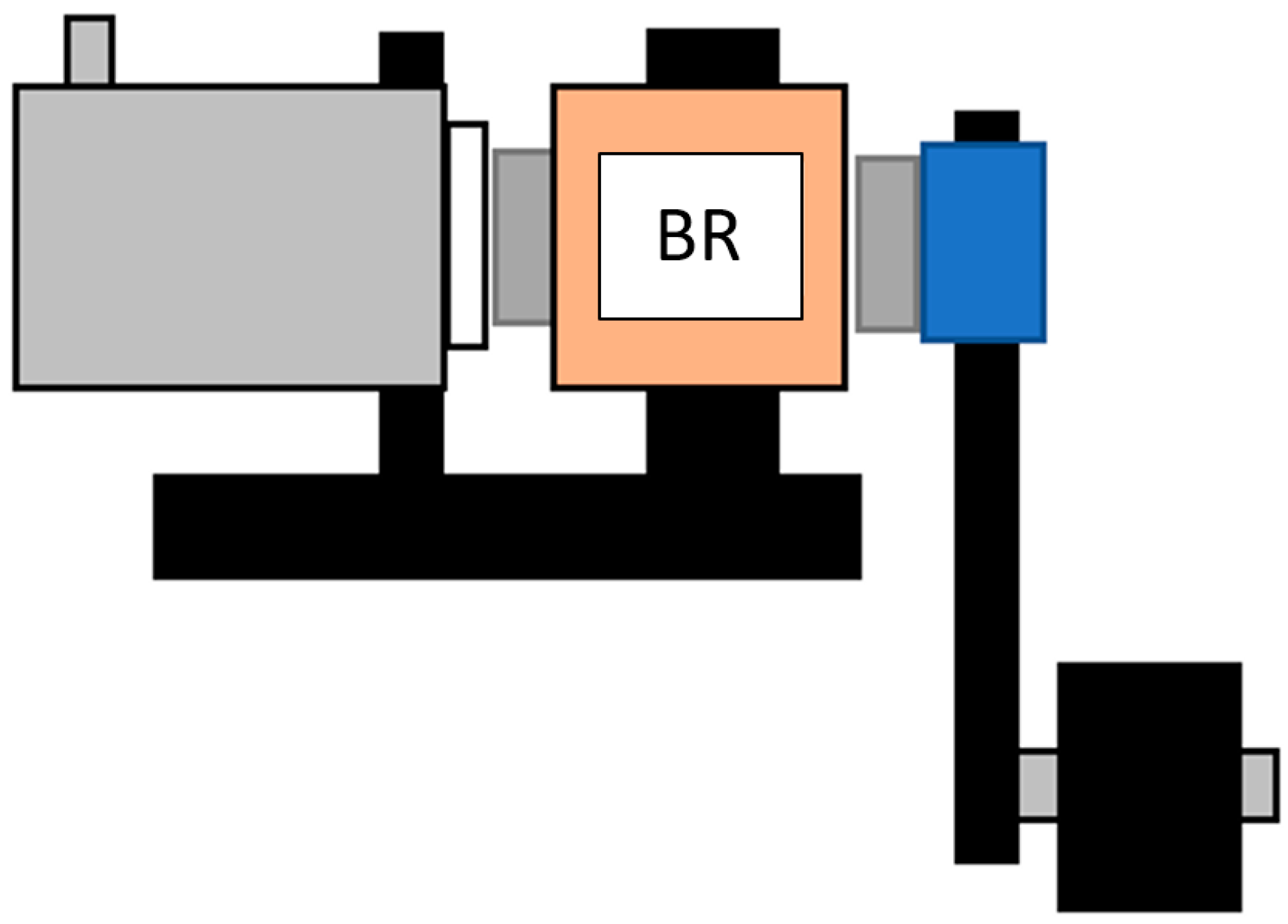
3.1. Measurement of BR Characteristics—Configuration A
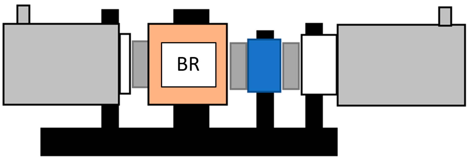
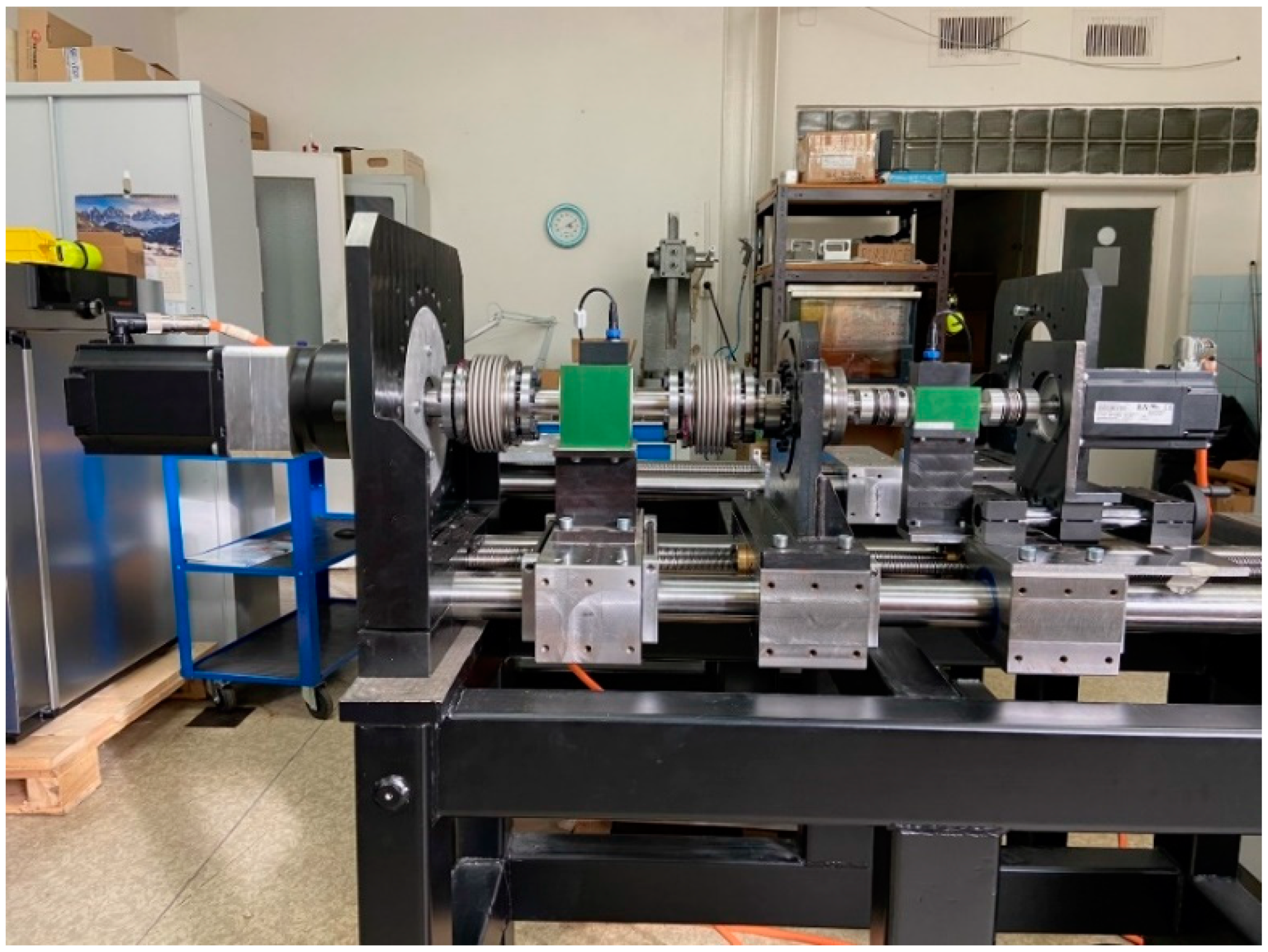
3.2. Measurement of BR Characteristics—Configuration B
- Lubricant analysis,
- ○
- changes in surface microgeometry, wear or abrasive (adhesive) abrasion. Contamination of the oil fill with solid particles of an abrasive nature, which cause an increase in the rate of wear and accelerate the increase in the BR backlash;
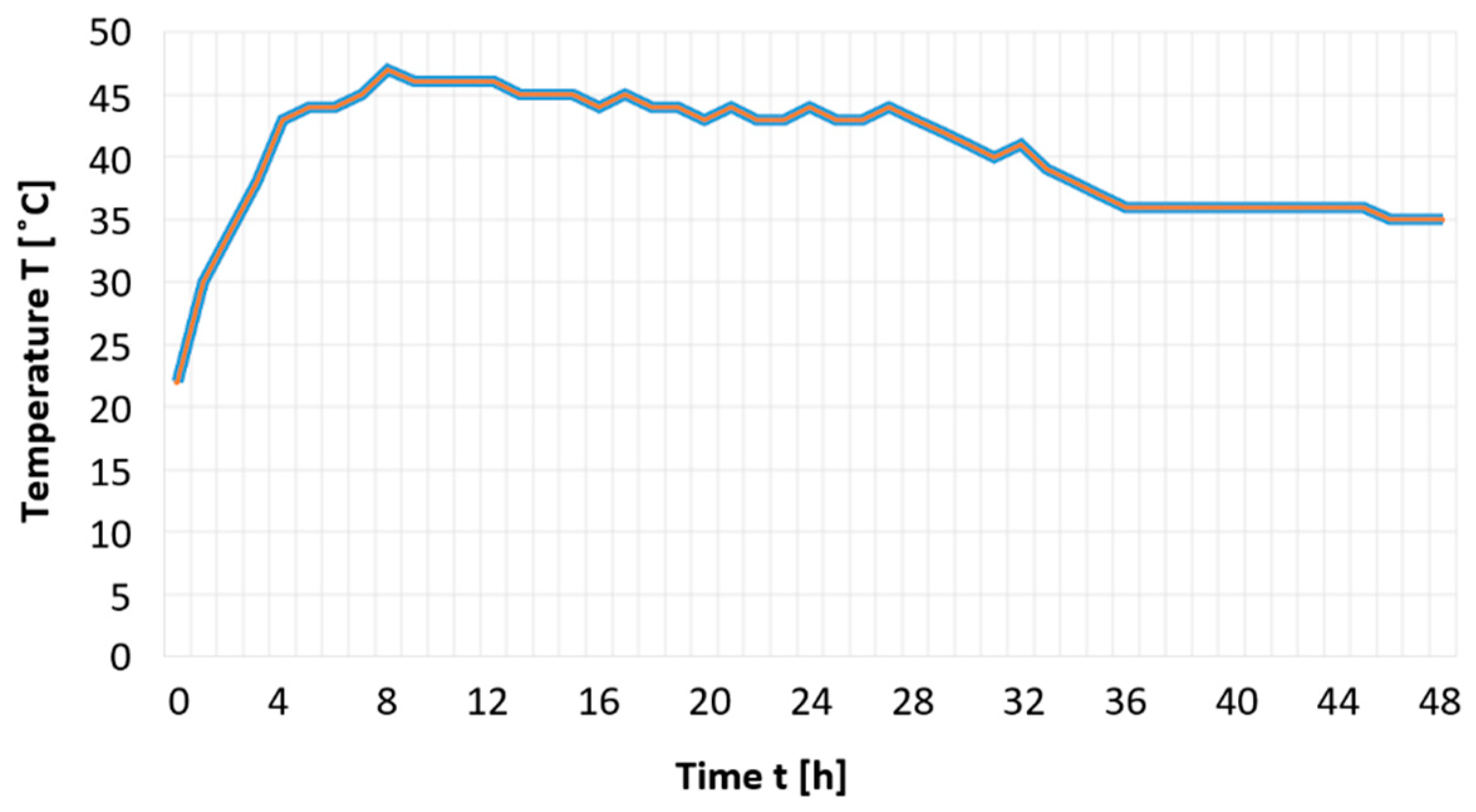
- Analysis of temperature changes;
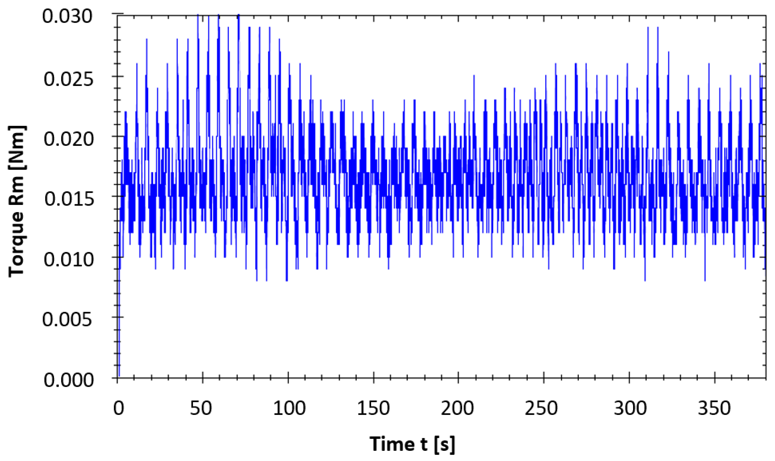
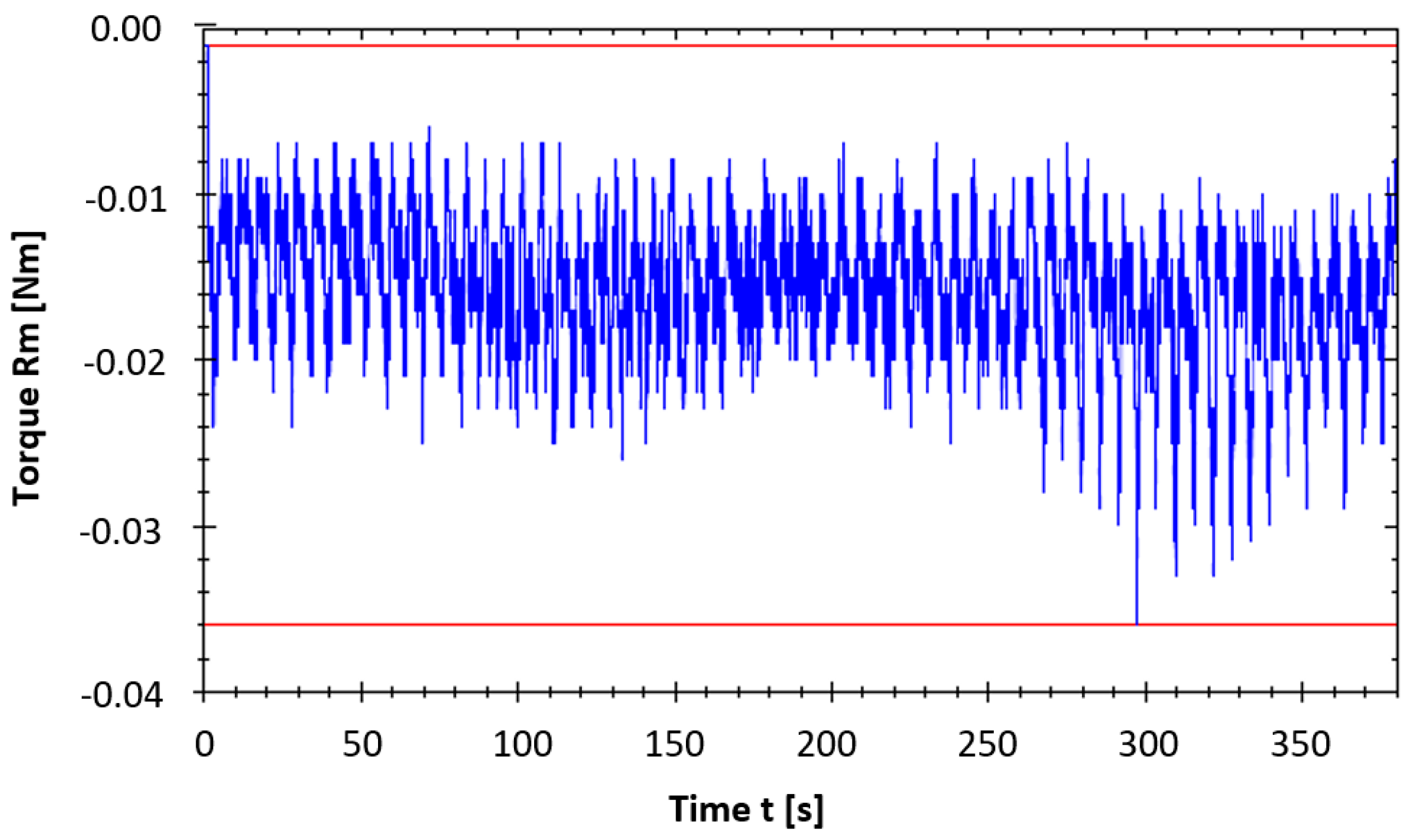
- Analysis of changes in starting torque—fluctuations;
- Analysis of H, LM changes;
- Analysis of changes in the system rigidity;
- Assessment of vibrations in the low frequency range;
- Assessment of vibrations in the high frequency range.
4. Characteristics of the Diagnostic Methods Applied
- ppm Fe abrasive particles were evaluated.
- Velocity measurement method (jitter speed), [mm/s] unit, RMS detection.
- According to the ISO 10816-3: 2009 recommendation, FFT (Fast Fourier Transform) spectrum for the frequency range 10–800 Hz.
- Enveloping Acceleration measurement method (method of measuring vibration acceleration in the high frequency range up to 10–20 kHz, through which the condition of roller bearings and gears is assessed), gE unit, PtP detection, for the frequency range 50–1000 Hz, FFT spectrum and time log.
- (Jitter) acceleration measurement method, g unit, PtP detection, frequency range up to 16 kHz, FFT spectrum and time log
- Enveloping Acceleration measurement method, gE unit, PtP detection, frequency range up to 10 kHz and up to 20 kHz, FFT spectrum and time log.
- SEE (Spectral Emitted Energy) measuring method—acoustic emissions (SKF), See unit, PtP detection, frequency range up to 600 kHz, FFT spectrum and time log.
- HFD measuring method—high frequency detection method (SKF), analysis of oscillations (accelerations) in the frequency range 40 kHz.
- Measuring method is used to assess lubrication, carrying capacity of oil film, metal contact, seizure, abrasion of contact surfaces (bearings and gears).
5. Conducting Measurements of Characteristic Properties of Bearing Reducers during Their Trial Run
5.1. Bearing Reducer Trial Run—Configuration A
- Input rotation speed: 10 rpm.
- Number of output flange revolutions completed: 1 revolution.
- Number of shaft revolutions completed: 63 revolutions.
- Sensor sampling frequency: 200 smps/s.
- Sensor resolution: 1:1.
- Ambient temperature: 21 °C ± 2.
- Torsional moment Mt (m = 4.0 kg on the arm of 0.425 m).
- When measuring Mt loaded to tipping moment Mc = 44 Nm.
- Average cycle torque Tave = 16 Nm.
- Average input speed nave = 2054 rpm.
- No cycle pause ≥ load factor Z = 100%.
- Acceleration time to 1000 rpm tacc = 0.5 s.
- Reverse cycle S8.
5.2. Trial Run of the Gear Reducer in Configuration B
- Input rotation speed: 10 rpm.
- Number of output flange revolutions completed: 1 revolution.
- Number of shaft revolutions completed: 63 revolutions.
- Sensor sampling frequency: 200 smps/s.
- Sensor resolution: 1:1.
- Ambient temperature: 21 °C ± 2.
- Torsional moment caused by the load applying drive.
- Average cycle torque Tave = 16.0 Nm.
- Average input speed nave = 2054 rpm.
- Acceleration time to 1000 rpm tacc = 0.5 s/1000 rpm.
- Reverse cycle S8.
6. Evaluation of Results and Qualitative Assessment of the Impact of the Load during the Trial Run Mode
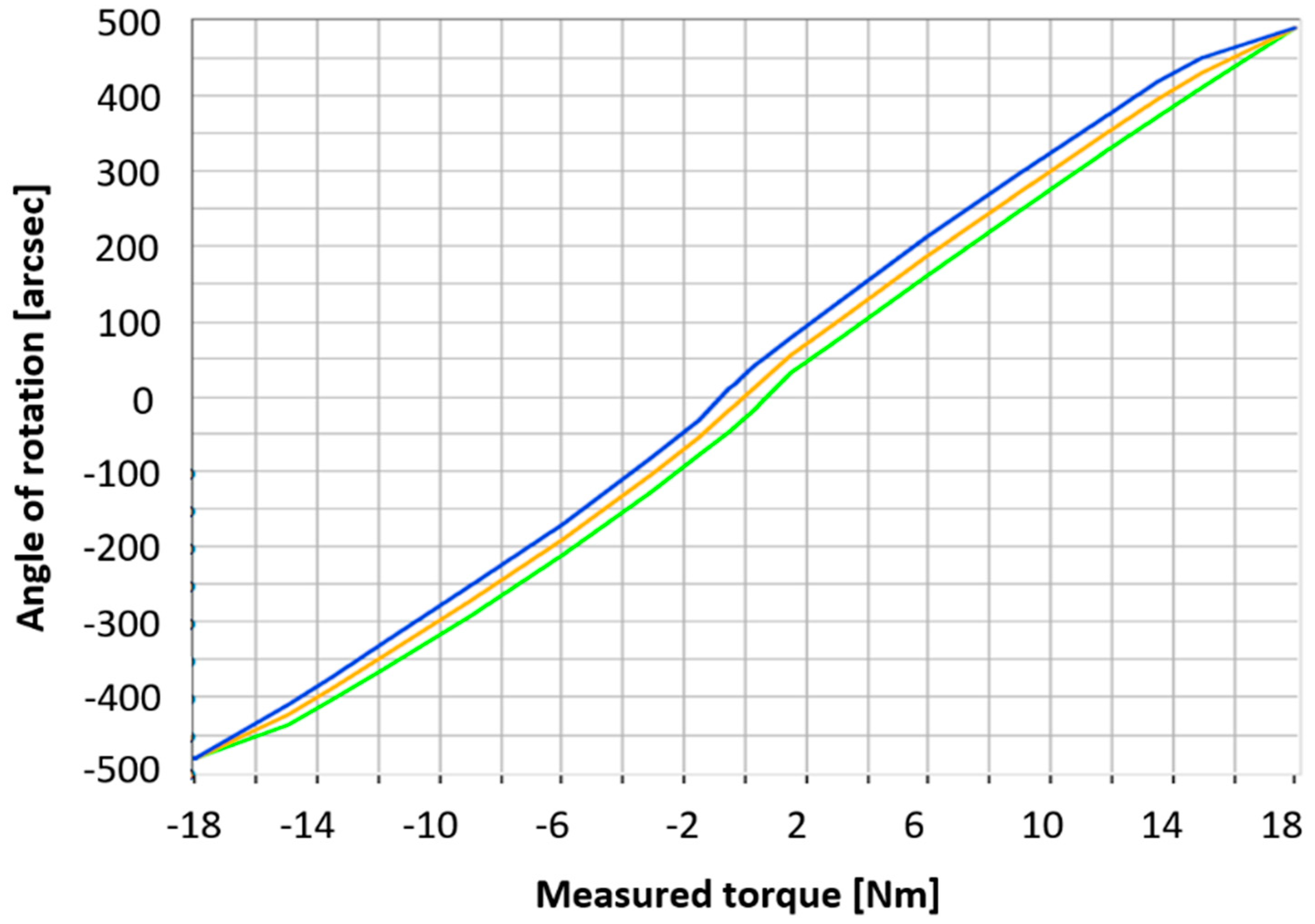
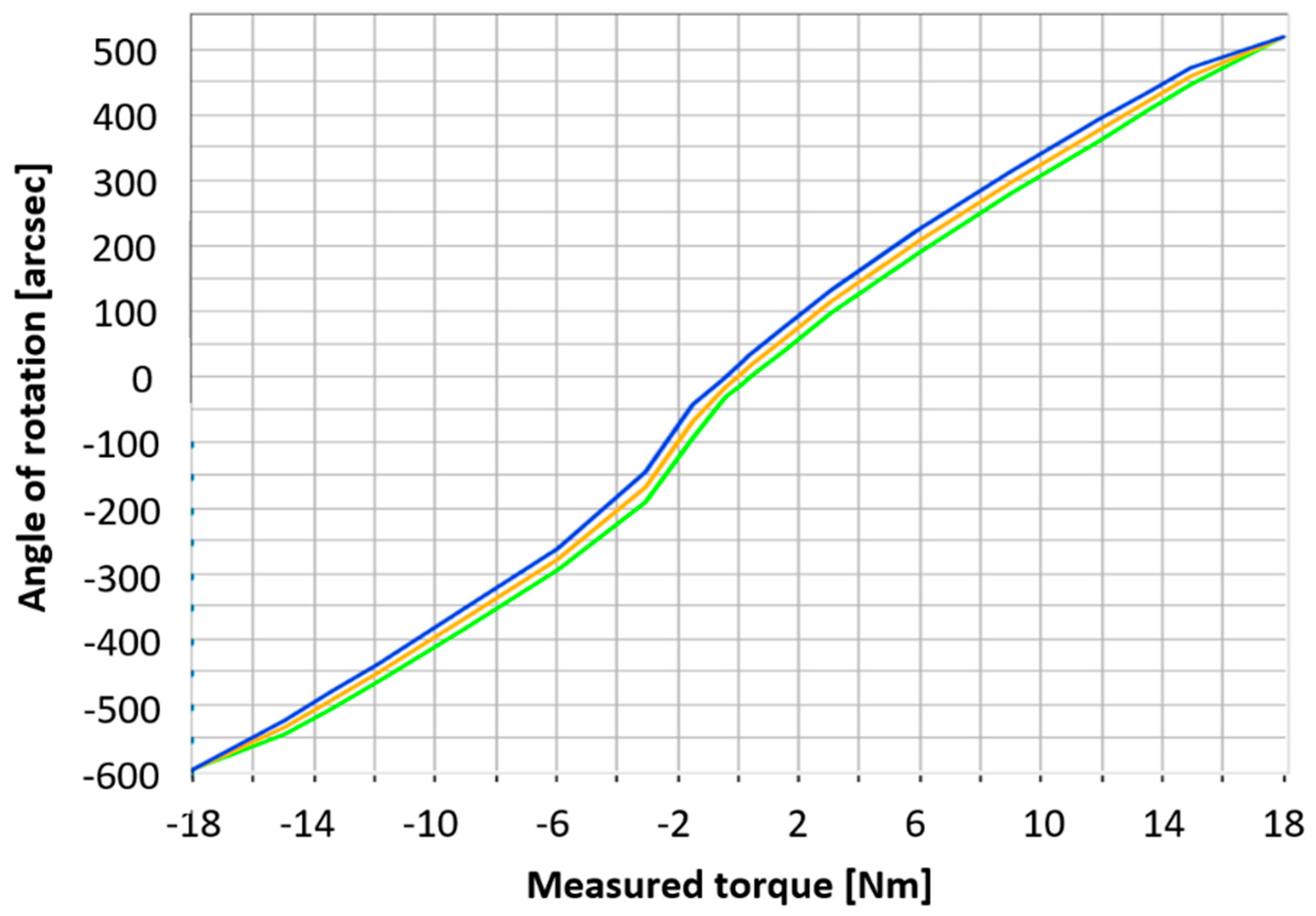
- From the point of view of measuring the lost motion and hysteresis: The choice of the type of load during the BR trial run had no effect on the change in the values of the lost motion parameter. The monitored hysteresis parameters showed a negligible increase in values. The hysteresis curve is a variable nonlinearity and depends on the position of rotation of the output flange and the perfection of component production.
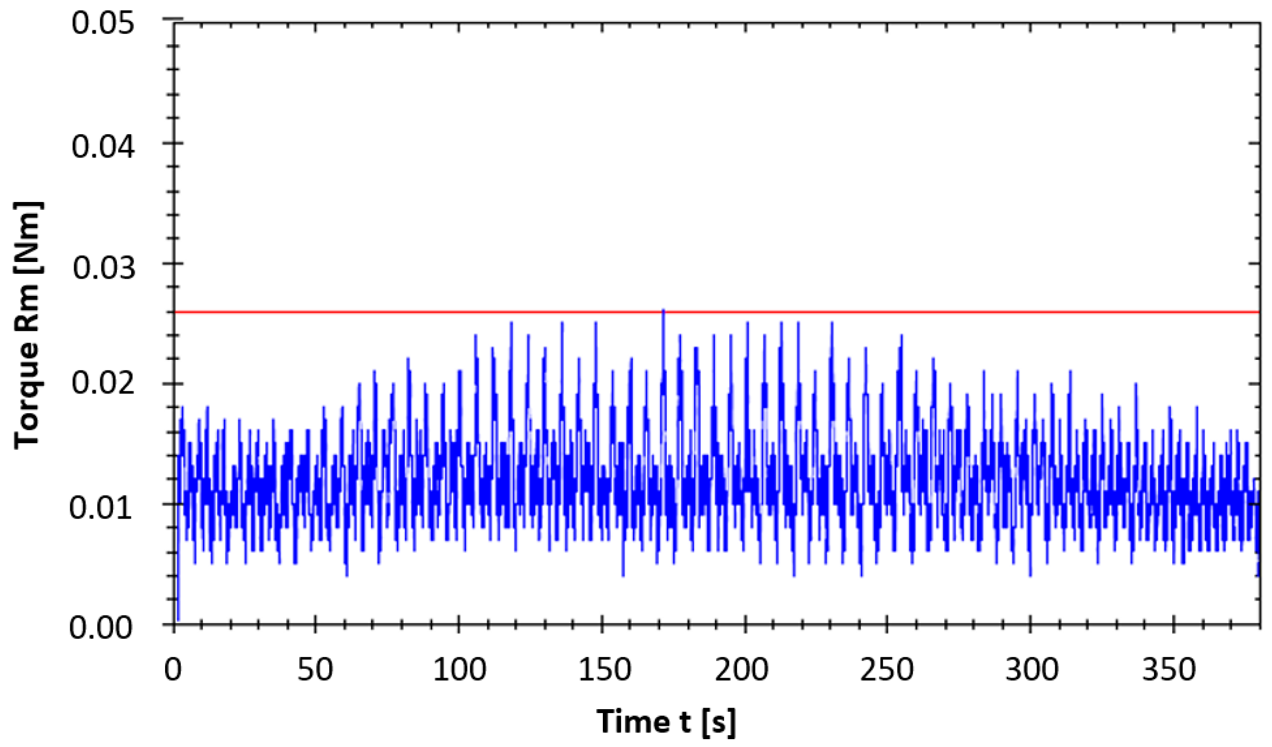
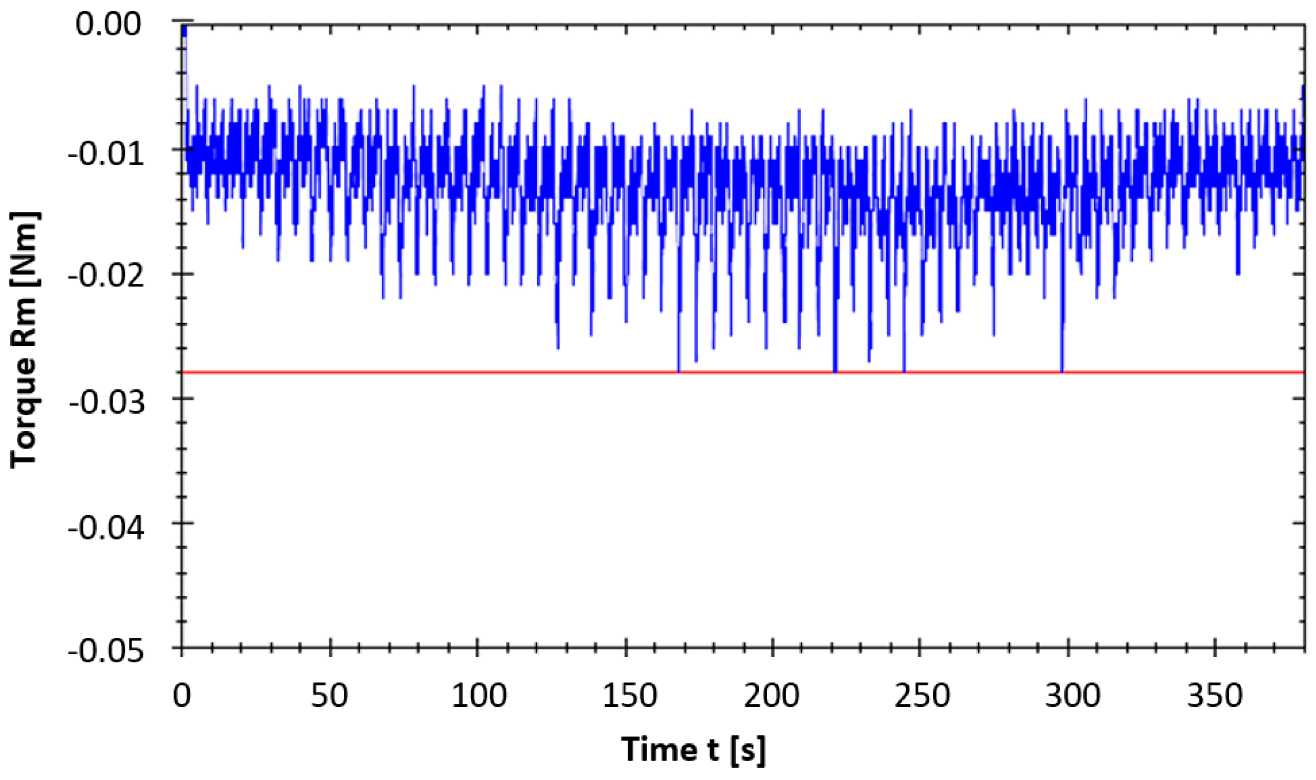
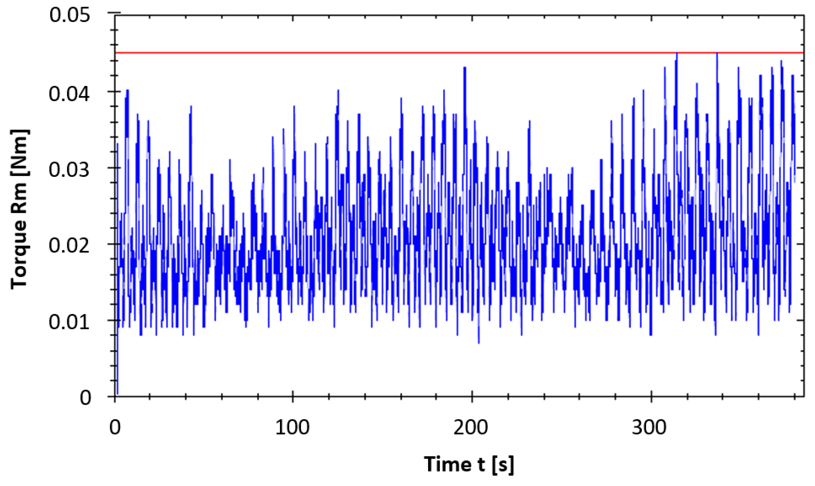
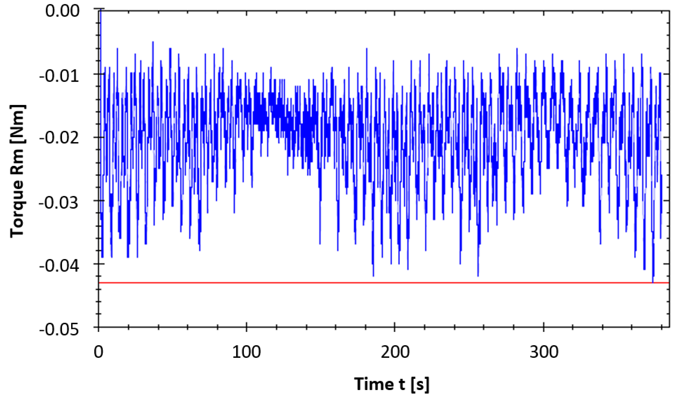
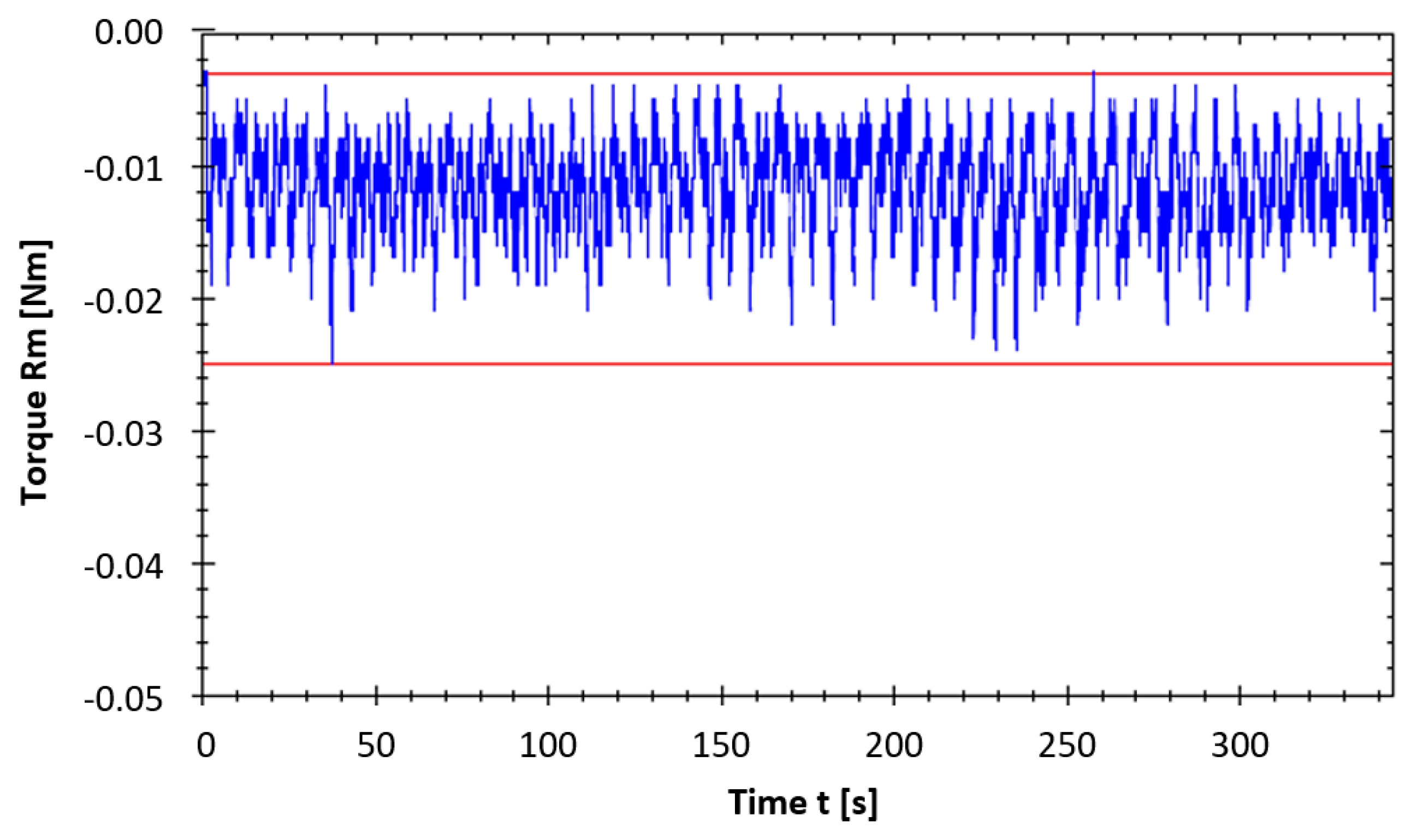
- From the point of view of measuring the starting torque: The choice of the type of load in the BR trial run had a demonstrable influence on the values of the parameter monitored—the starting torque and fluctuation of the starting torque. In the trial run with a load, a sinusoidal load is applied to the kinematic pairs, which are evenly loaded by a servomotor with a torque sensor (controlled torque value) during the load application process by the drive. In both trial run methods, the surfaces were smoothed, which was reflected in the torque fluctuation—a drop in the peaks. A decrease in the mean value of the starting torque was recorded when the load was applied by the drive.
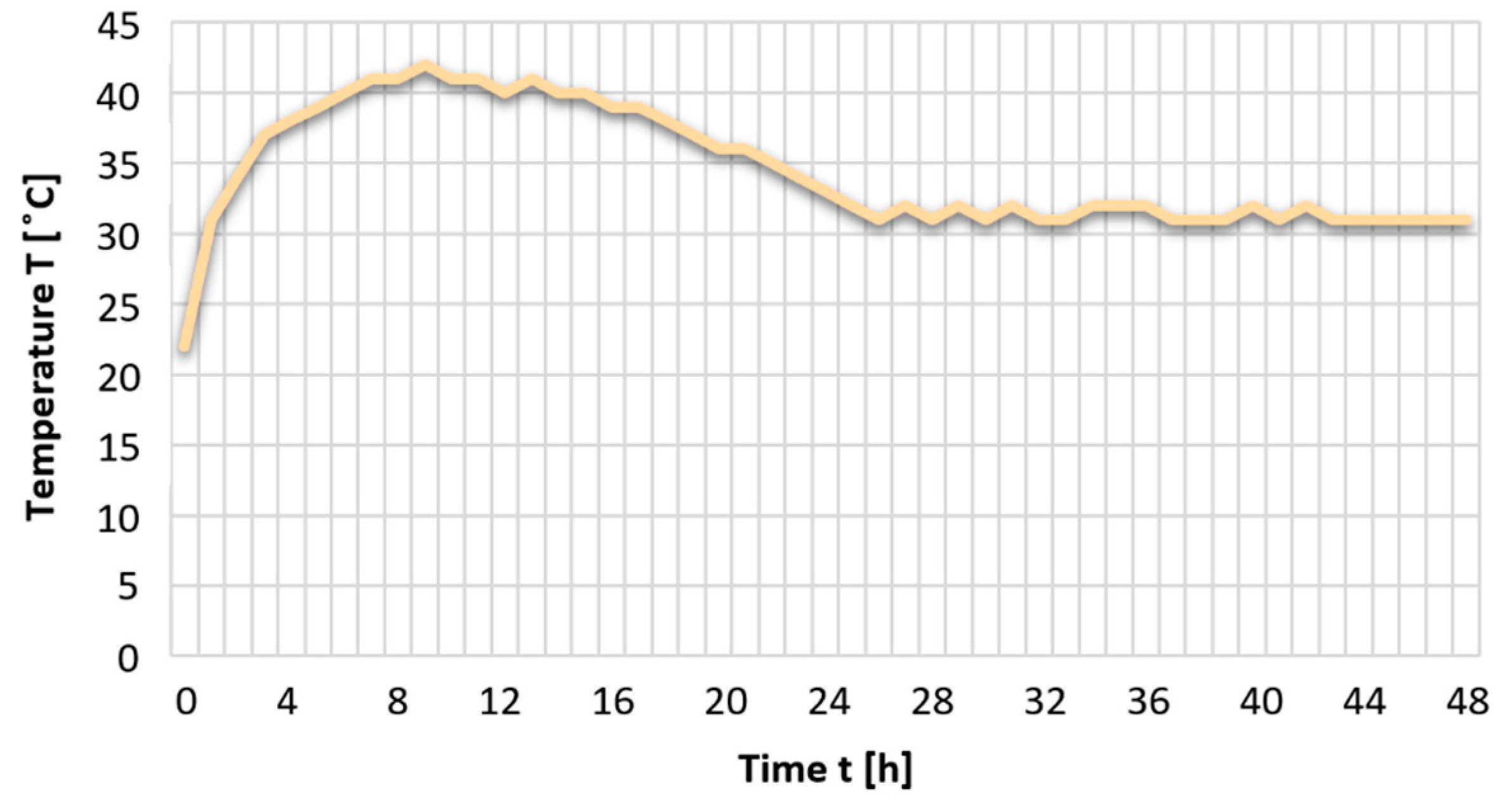
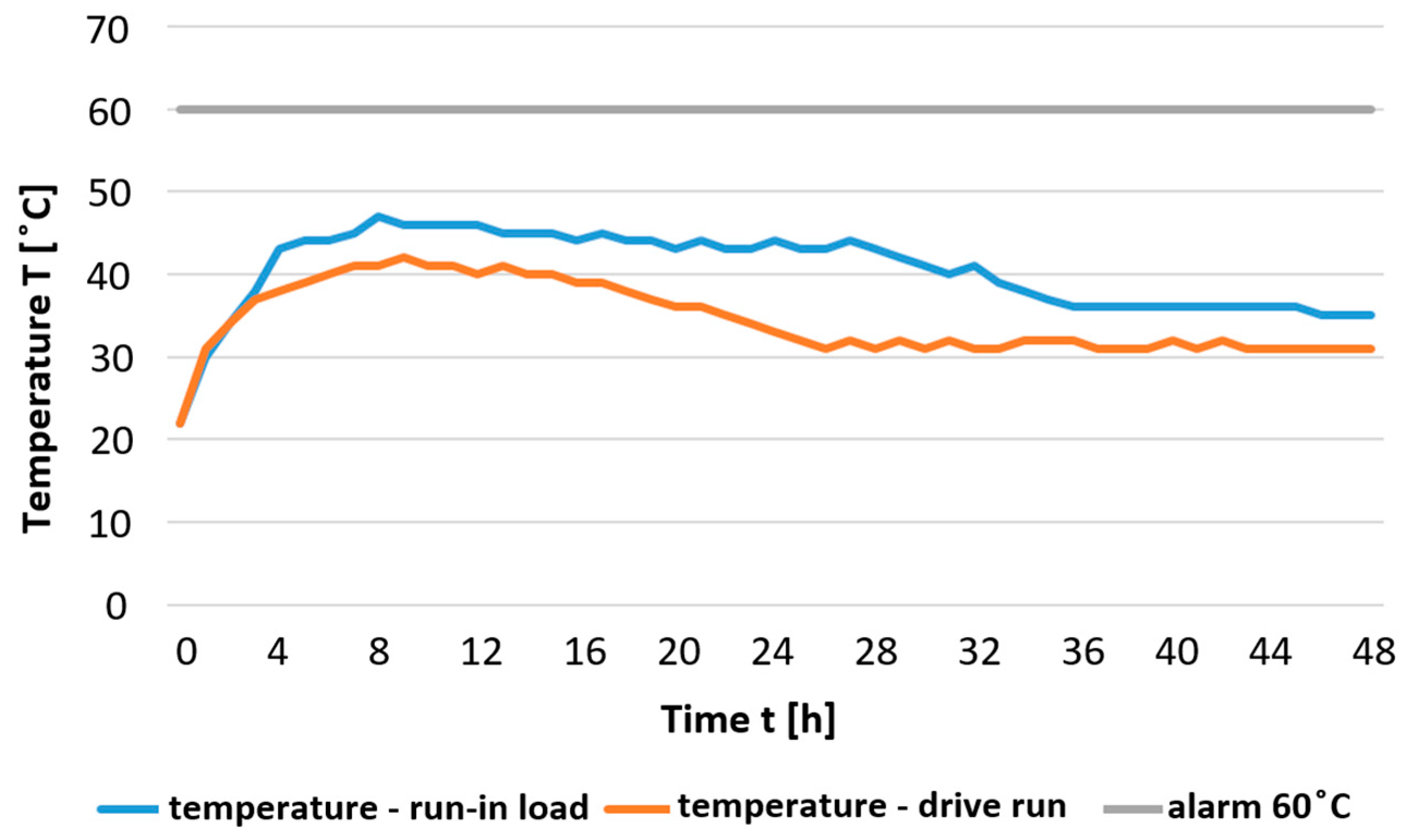
- From the point of view of temperature measurement: After the initial increase in the surface temperature BR, the friction regime stabilized, and the temperatures decreased and became stable. The alarm value was not exceeded during the measurement, which can be seen in Figure 20.
- In terms of the lubricant condition: After the initial phase of the relative trial run, the Castrol Tribol GR TT1 PD lubricant used showed a satisfactory Fe content of abrasive particles (all sample values were below the recommended limit).
7. Conclusions
- Reducer trial run over 48 h, max. 60 °C temperature NT, 50% TR at max. 1000 rpm.
- Measurement of abrasion Fe particles—max. Fe content of particles 50 ppm.
- Measurement of the reducer starting torque—input 10 rpm, upon completion of one rotation of the output BR member, at the sampling frequency of the sensor of 200 samples per second.
- Measurement of hysteresis (H) and lost motion (LM)—in load-free state, TR = 100% Nm in both directions (CW, CCW), evaluation at 3% TR load.
- Angular transmission error measurement (ATE)—in load-free state, output 0–720°, in both directions (CW, CCW).
- Repeated accuracy measurement—output rotation 1800°, eight desired positions at 360°.
Author Contributions
Funding
Institutional Review Board Statement
Informed Consent Statement
Data Availability Statement
Acknowledgments
Conflicts of Interest
References
- Baron, P.; Kocisko, M.; Dobransky, J.; Pollak, M.; Cmorej, T. Research and correlation of diagnostic methods for assessment of the state of oil filling in cycloid gearbox. Adv. Mater. Sci. Eng. 2015, 2015, 597841. [Google Scholar] [CrossRef]
- Legutko, S. Development trends in machines operation maintenance. Eksploat. I Niezawodn. Maint. Reliab. 2009, 2, 8–16. [Google Scholar]
- Baron, P.; Kocisko, M.; Dobransky, J.; Pollak, M.; Torokova, M. Research and application of methods of technical diagnostics for the verification of the design. Measurement 2016, 94, 245–253. [Google Scholar] [CrossRef]
- Sorin-Dumitru, G.; Vasile, C. Industrial automation in the relative spiral feed and contact contour during cold orbital deformation. Int. Conf. Qual. Innov. Eng. Manag. 2012, 13, 367–370. [Google Scholar]
- Olejarova, S.; Dobransky, J.; Svetlik, J.; Pituk, M. Measurements and evaluation of measurements of vibrations in steel milling process. Measurement 2017, 106, 18–25. [Google Scholar] [CrossRef]
- Krolczyk, G.; Legutko, S.; Stoic, A. Influence of the cutting parameters and conditions onto surface hardness of duplex stainless steel after turning. Teh. Vjesn. Tech. Gaz. 2013, 20, 1077–1080. [Google Scholar]
- Stejskal, T.; Svetlik, J.; Dovica, M.; Demec, P.; Kral, J. Measurement of static stiffness after motion on a three-axis CNC milling table. Appl. Sci. 2018, 8, 15. [Google Scholar] [CrossRef]
- Pham, A.D.; Ahn, H.J. High precision reducers for industrial robots driving 4th industrial revolution: State of arts, analysis, design, performance evaluation and perspective. Int. J. Precis. Eng. Manuf.-Green Technol. 2018, 5, 519–533. [Google Scholar] [CrossRef]
- Blagojevic, M.; Marjanovic, N.; Djordjevic, Z.; Stojanovic, B.; Disic, A. A new design of a two-stage cycloidal speed reducer. J. Mech. Des. 2011, 133, 085001. [Google Scholar] [CrossRef]
- Litvin, F.L.; Feng, P.H. Computerized design and generation of cycloidal gearings. Mech. Mach. Theory 1996, 31, 891–911. [Google Scholar] [CrossRef]
- Mao, H.; Liu, G.; Zeng, D.; Cao, Y.; He, K.; Du, R. A new design of cycloidal planetary reducer with internal cycloidal profile. ASME 2018 Int. Mech. Eng. Congr. Expo. 2018, 1–8. [Google Scholar] [CrossRef]
- Sun, X.; Han, L.; Wang, J. Tooth modification and loaded tooth contact analysis of China bearing reducer. Proc. Inst. Mech. Eng. Part C J. Mech. Eng. Sci. 2019, 233, 6240–6261. [Google Scholar] [CrossRef]
- Huang, Y.; Du, X.; Zhu, C.; Ni, G.; Ullah, N.; Liu, H. Mesh stiffness analysis of beveloid gears for the rotating vector transmission. J. Mech. Sci. Technol. 2019, 33, 3943–3953. [Google Scholar] [CrossRef]
- Pham, A.D.; Ahn, H.J. Efficiency analysis of a cycloid reducer considering tolerance. J. Frict. Wear 2017, 38, 490–496. [Google Scholar] [CrossRef]
- Terakawa, T.; Komori, M.; Morita, Y. Motion analysis and experiments of reducer-integrated motor using strain wave gearing system. In Proceedings of the ASME 2018 International Design Engineering Technical Conferences and Computers and Information in Engineering Conference, Quebec City, QC, Canada, 26–29 August 2018; pp. 1–6. [Google Scholar] [CrossRef]
- Gorla, C.; Davoli, P.; Rosa, F.; Longoni, C.; Chiozzi, F.; Samarani, A. Theoretical and experimental analysis of a cycloidal speed reducer. J. Mech. Des. 2008, 130, 112604. [Google Scholar] [CrossRef]
- Yamada, S.; Fujimoto, H. Precise joint torque control method for two-inertia system with backlash using load-side encoder. IEEJ J. Ind. Appl. 2019, 8, 75–83. [Google Scholar] [CrossRef]
- Shih, Y.P.; Lo, S.H.; Sheen, B.T.; Tsai, Y.H. Precision evaluation for cycloidal gears. In Proceedings of the ASME 2019 International Design Engineering Technical Conferences and Computers and Information in Engineering Conference, Anaheim, CA, USA, 18–21 August 2019; pp. 1–5. [Google Scholar] [CrossRef]
- Executive Summary World Robotics 2016 Industrial Robots. Available online: http://www.ifr.org/fileadmin/user_upload/downloads/World_Robotics/2016/Executive_Summary_WR_Industrial_Robots_2016.pdf (accessed on 10 April 2020).
- Xiong, Y.; Huang, K.; Xu, F.; Yi, Y.; Sang, M.; Zhai, H. Research on the influence of backlash on mesh stiffness and the nonlinear dynamics of spur gears. Appl. Sci. 2019, 9, 1029. [Google Scholar] [CrossRef]
- Margielewicz, J.; Gąska, D.; Litak, G. Modelling of the gear backlash. Nonlinear Dyn. 2019, 97, 355–368. [Google Scholar] [CrossRef]
- Getachew, A.A.; Hirpa, G.L. Effect of backlash on transmission error and time varying mesh stiffness. In International Workshop of Advanced Manufacturing and Automation; Springer: Singapore, 2021; Volume 737, pp. 18–28. [Google Scholar] [CrossRef]
- Spitas, C.; Spitas, V. Coupled multi-DOF dynamic contact analysis model for the simulation of intermittent gear tooth contacts, impacts and rattling considering backlash and variable torque. J. Mech. Eng. Sci. 2016, 230, 1022–1047. [Google Scholar] [CrossRef]
- Walha, L.; Fakhfakh, T.; Haddar, M. Nonlinear dynamics of a twostage gear system with mesh stiffness fluctuation, bearing flexibility and backlash. Mech. Mach. Theory 2009, 44, 1058–1069. [Google Scholar] [CrossRef]
- Xue, J.; Qiu, Z.; Fang, L.; Lu, Y.; Hu, W. Angular measurement of high precision reducer for industrial robot. IEEE Trans. Instrum. Meas. 2021, 70, 1–6. [Google Scholar] [CrossRef]
- Caldarola, F.; Maiolo, M.; Solferino, V. A new approach to the Z-transform through infinite computation. Commun. Nonlinear Sci. Numer. Simul. 2020, 82, 105019. [Google Scholar] [CrossRef]
- Farshidianfar, A.; Saghafi, A. Global bifurcation and chaos analysis in nonlinear vibration of spur gear systems. Nonlinear Dyn. 2014, 75, 783–806. [Google Scholar] [CrossRef]
- Truxal, J.G. Control Engineers’ Handbook: Servo-Mechanisms; McGraw-Hill: New York, NY, USA, 1958; p. 1112. [Google Scholar]
- Xu, H.; Shi, Z.Y.; Yu, B.; Wang, H. Optimal measurement speed and its determination method in the transmission precision evaluation of precision reducers. Appl. Sci. 2019, 9, 2146. [Google Scholar] [CrossRef]
- Hric, M.; Durovsky, F.; Fedak, V. Influence of non-linearities of cycloid gearbox. ATP J. 2012, 9, 42–44. [Google Scholar]



| TS 050 | ||
|---|---|---|
| Gear ratio | i | 63 |
| Nominal output torque 100% | TR 100% [Nm] | 18 |
| Nominal output torque 50% | TR 50% [Nm] | 9 |
| Rated output speed | nR [rpm] | 1000 |
| Vibration measurement | - | Yes |
| Lubricant analysis | - | Yes |
| Amount of lubricant | [cm3] | 2.85 |
| Lubricant type | Castrol Tribol TT1 PD | |
| No. | Type BR/Serial No | Lost Motion [arcmin] | Hysteresis [arcmin] | Rm (CW) [Nm] | Rm (CCW) [Nm] |
|---|---|---|---|---|---|
| 1. | TS 050 s/n.1901 | 0.57 | 0.42 | 0.030 | 0.036 |
| 2. | TS 050 s/n.1902 | 0.64 | 0.55 | 0.031 | 0.023 |
| 3. | TS 050 s/n.1903 | 0.57 | 0.44 | 0.027 | 0.021 |
| 4. | TS 050 s/n.1904 | 0.52 | 0.55 | 0.024 | 0.017 |
| 5. | TS 050 s/n.1905 | 0.53 | 0.45 | 0.027 | 0.033 |
| 6. | TS 050 s/n.1906 | 0.55 | 0.42 | 0.032 | 0.024 |
| 7. | TS 050 s/n.1907 | 0.69 | 0.41 | 0.039 | 0.044 |
| 8. | TS 050 s/n.1908 | 0.55 | 0.53 | 0.030 | 0.027 |
| 9. | TS 050 s/n.1909 | 0.51 | 0.52 | 0.039 | 0.044 |
| 10. | TS 050 s/n.1910 | 0.64 | 0.44 | 0.037 | 0.043 |
| No. | Type BR/Serial No | Content Fe (ppm) after 8 h | Content Fe (ppm) after 16 h | Content Fe (ppm) after 24 h | Content Fe (ppm) after 32 h | Content Fe (ppm) after 48 h |
|---|---|---|---|---|---|---|
| 1. | TS 050 s/n.1901 | 7 | 10 | 12 | 14 | 16 |
| 2. | TS 050 s/n.1902 | 8 | 12 | 13 | 15 | 16 |
| 3. | TS 050 s/n.1903 | 9 | 11 | 14 | 16 | 17 |
| 4. | TS 050 s/n.1904 | 10 | 13 | 16 | 18 | 18 |
| 5. | TS 050 s/n.1905 | 9 | 12 | 15 | 17 | 18 |
| 6. | TS 050 s/n.1906 | 11 | 12 | 14 | 16 | 17 |
| 7. | TS 050 s/n.1907 | 8 | 11 | 13 | 15 | 16 |
| 8. | TS 050 s/n.1908 | 12 | 13 | 16 | 18 | 19 |
| 9. | TS 050 s/n.1909 | 9 | 14 | 16 | 17 | 17 |
| 10. | TS 050 s/n.1910 | 10 | 13 | 14 | 16 | 17 |
| No. | Type BR/Serial No | Natural Frequency Radial—Torsional [RPM/Hz] | Natural Frequency Axially—Tipping [RPM/Hz] |
|---|---|---|---|
| 1. | TS 050 s/n.1901 | 840/14.0 | 1260/21.0 |
| 2. | TS 050 s/n.1902 | 825/13.0 | 1210/20.0 |
| 3. | TS 050 s/n.1903 | 831/12.5 | 1245/21.0 |
| 4. | TS 050 s/n.1904 | 844/14.0 | 1270/20.0 |
| 5. | TS 050 s/n.1905 | 837/13.0 | 1233/19.0 |
| 6. | TS 050 s/n.1906 | 833/12.0 | 1250/18.5 |
| 7. | TS 050 s/n.1907 | 842/14.0 | 1280/21.0 |
| 8. | TS 050 s/n.1908 | 830/13.0 | 1310/22.0 |
| 9. | TS 050 s/n.1909 | 820/11.0 | 1240/19.0 |
| 10. | TS 050 s/n.1910 | 835/11.5 | 1260/20.0 |
| No. | Type BR/Serial No. | Lost Motion [arcmin] | Hysteresis [arcmin] | Rm (CW) [Nm] | Rm (CCW) [Nm] |
|---|---|---|---|---|---|
| 1. | TS 050 s/n.1901 | 0.57 | 0.45 | 0.026 | 0.023 |
| 2. | TS 050 s/n.1902 | 0.64 | 0.59 | 0.025 | 0.019 |
| 3. | TS 050 s/n.1903 | 0.57 | 0.51 | 0.021 | 0.017 |
| 4. | TS 050 s/n.1904 | 0.52 | 0.64 | 0.019 | 0.015 |
| 5. | TS 050 s/n.1905 | 0.53 | 0.49 | 0.022 | 0.024 |
| 6. | TS 050 s/n.1906 | 0.55 | 0.47 | 0.028 | 0.020 |
| 7. | TS 050 s/n.1907 | 0.69 | 0.45 | 0.032 | 0.032 |
| 8. | TS 050 s/n.1908 | 0.55 | 0.62 | 0.024 | 0.023 |
| 9. | TS 050 s/n.1909 | 0.51 | 0.59 | 0.030 | 0.038 |
| 10. | TS 050 s/n.1910 | 0.64 | 0.52 | 0.029 | 0.037 |
| No. | Type BR/Serial No. | Lost Motion [Arcmin] | Hysteresis [Arcmin] | Rm (CW) [Nm] | Rm (CCW) [Nm] |
|---|---|---|---|---|---|
| 1. | TS 050 s/n.1901 | 0 | +0.03 | −0.004 | −0.013 |
| 2. | TS 050 s/n.1902 | 0 | +0.04 | −0.006 | −0.004 |
| 3. | TS 050 s/n.1903 | 0 | +0.07 | −0.006 | −0.004 |
| 4. | TS 050 s/n.1904 | 0 | +0.09 | −0.005 | −0.002 |
| 5. | TS 050 s/n.1905 | 0 | +0.04 | −0.005 | −0.009 |
| 6. | TS 050 s/n.1906 | 0 | +0.05 | −0.004 | −0.004 |
| 7. | TS 050 s/n.1907 | 0 | +0.04 | −0.007 | −0.012 |
| 8. | TS 050 s/n.1908 | 0 | +0.09 | −0.006 | −0.004 |
| 9. | TS 050 s/n.1909 | 0 | +0.07 | −0.009 | −0.004 |
| 10. | TS 050 s/n.1910 | 0 | +0.08 | −0.008 | −0.006 |
| No. | Type BR/Serial No. | Lost Motion [arcmin] | Hysteresis [arcmin] | Rm (CW) [Nm] | Rm (CCW) [Nm] |
|---|---|---|---|---|---|
| 1. | TS 050 s/n.1911 | 0.73 | 0.55 | 0.045 | 0.043 |
| 2. | TS 050 s/n.1912 | 0.65 | 0.95 | 0.035 | 0.041 |
| 3. | TS 050 s/n.1913 | 0.80 | 1.11 | 0.040 | 0.046 |
| 4. | TS 050 s/n.1914 | 0.78 | 0.63 | 0.032 | 0.038 |
| 5. | TS 050 s/n.1915 | 0.62 | 1.00 | 0.042 | 0.050 |
| 6. | TS 050 s/n.1916 | 0.71 | 0.82 | 0.051 | 0.046 |
| 7. | TS 050 s/n.1917 | 0.82 | 1.04 | 0.036 | 0.040 |
| 8. | TS 050 s/n.1918 | 0.90 | 0.74 | 0.044 | 0.042 |
| 9. | TS 050 s/n.1919 | 0.55 | 0.67 | 0.032 | 0.039 |
| 10. | TS 050 s/n.1920 | 0.76 | 0.90 | 0.028 | 0.034 |
| No. | Type BR/Serial No. | Content Fe (ppm) after 8 h | Content Fe (ppm) after 16 h | Content Fe (ppm) after 24 h | Content Fe (ppm) after 32 h | Content Fe (ppm) after 48 h |
|---|---|---|---|---|---|---|
| 1. | TS 050 s/n.1911 | 9 | 10 | 10 | 14 | 14 |
| 2. | TS 050 s/n.1912 | 7 | 8 | 11 | 12 | 12 |
| 3. | TS 050 s/n.1913 | 11 | 12 | 12 | 14 | 15 |
| 4. | TS 050 s/n.1914 | 8 | 10 | 11 | 12 | 13 |
| 5. | TS 050 s/n.1915 | 7 | 9 | 10 | 11 | 13 |
| 6. | TS 050 s/n.1916 | 9 | 11 | 12 | 14 | 14 |
| 7. | TS 050 s/n.1917 | 8 | 9 | 11 | 13 | 13 |
| 8. | TS 050 s/n.1918 | 7 | 10 | 12 | 14 | 14 |
| 9. | TS 050 s/n.1919 | 9 | 9 | 11 | 13 | 14 |
| 10. | TS 050 s/n.1920 | 7 | 8 | 9 | 11 | 11 |
| No. | Type BR/Serial No. | Natural Frequency Radial—Torsional [rpm/Hz] |
|---|---|---|
| 1. | TS 050 s/n.1911 | 820/11.3 |
| 2. | TS 050 s/n.1912 | 830/12.0 |
| 3. | TS 050 s/n.1913 | 815/13.0 |
| 4. | TS 050 s/n.1914 | 835/12.0 |
| 5. | TS 050 s/n.1915 | 824/11.5 |
| 6. | TS 050 s/n.1916 | 822/13.0 |
| 7. | TS 050 s/n.1917 | 838/12.5 |
| 8. | TS 050 s/n.1918 | 832/13.0 |
| 9. | TS 050 s/n.1919 | 840/11.0 |
| 10. | TS 050 s/n.1920 | 837/14.0 |
| No. | Type BR/Serial No. | Lost Motion [arcmin] | Hysteresis [arcmin] | Rm (CW) [Nm] | Rm (CCW) [Nm] |
|---|---|---|---|---|---|
| 1. | TS 050 s/n.1911 | 0.73 | 0.59 | 0.026 | 0.025 |
| 2. | TS 050 s/n.1912 | 0.65 | 1.00 | 0.030 | 0.028 |
| 3. | TS 050 s/n.1913 | 0.80 | 1.13 | 0.028 | 0.031 |
| 4. | TS 050 s/n.1914 | 0.78 | 0.65 | 0.025 | 0.026 |
| 5. | TS 050 s/n.1915 | 0.62 | 1.05 | 0.036 | 0.029 |
| 6. | TS 050 s/n.1916 | 0.71 | 0.84 | 0.030 | 0.032 |
| 7. | TS 050 s/n.1917 | 0.82 | 1.08 | 0.024 | 0.028 |
| 8. | TS 050 s/n.1918 | 0.90 | 0.75 | 0.029 | 0.030 |
| 9. | TS 050 s/n.1919 | 0.55 | 0.70 | 0.020 | 0.027 |
| 10. | TS 050 s/n.1920 | 0.76 | 0.93 | 0.021 | 0.024 |
| No. | Type BR/Serial No. | Lost Motion [arcmin] | Hysteresis [arcmin] | Rm (CW) [Nm] | Rm (CCW) [Nm] |
|---|---|---|---|---|---|
| 1. | TS 050 s/n.1911 | 0 | +0.04 | −0.019 | −0.018 |
| 2. | TS 050 s/n.1912 | 0 | +0.05 | −0.005 | −0.013 |
| 3. | TS 050 s/n.1913 | 0 | +0.02 | −0.012 | −0.015 |
| 4. | TS 050 s/n.1914 | 0 | +0.02 | −0.007 | −0.012 |
| 5. | TS 050 s/n.1915 | 0 | +0.05 | −0.006 | −0.021 |
| 6. | TS 050 s/n.1916 | 0 | +0.02 | −0.021 | −0.014 |
| 7. | TS 050 s/n.1917 | 0 | +0.04 | −0.012 | −0.012 |
| 8. | TS 050 s/n.1918 | 0 | +0.01 | −0.015 | −0.012 |
| 9. | TS 050 s/n.1919 | 0 | +0.03 | −0.012 | −0.012 |
| 10. | TS 050 s/n.1920 | 0 | +0.03 | −0.007 | −0.010 |
Publisher’s Note: MDPI stays neutral with regard to jurisdictional claims in published maps and institutional affiliations. |
© 2021 by the authors. Licensee MDPI, Basel, Switzerland. This article is an open access article distributed under the terms and conditions of the Creative Commons Attribution (CC BY) license (https://creativecommons.org/licenses/by/4.0/).
Share and Cite
Kočiško, M.; Pollák, M.; Töröková, M.; Baron, P.; Paulišin, D.; Kundrík, J. Determination of Methodology and Research of the Influence of the Trial Run of High-Precision Reducers on the Change of Their Characterizing Properties. Appl. Sci. 2021, 11, 3859. https://doi.org/10.3390/app11093859
Kočiško M, Pollák M, Töröková M, Baron P, Paulišin D, Kundrík J. Determination of Methodology and Research of the Influence of the Trial Run of High-Precision Reducers on the Change of Their Characterizing Properties. Applied Sciences. 2021; 11(9):3859. https://doi.org/10.3390/app11093859
Chicago/Turabian StyleKočiško, Marek, Martin Pollák, Monika Töröková, Petr Baron, Dušan Paulišin, and Juraj Kundrík. 2021. "Determination of Methodology and Research of the Influence of the Trial Run of High-Precision Reducers on the Change of Their Characterizing Properties" Applied Sciences 11, no. 9: 3859. https://doi.org/10.3390/app11093859
APA StyleKočiško, M., Pollák, M., Töröková, M., Baron, P., Paulišin, D., & Kundrík, J. (2021). Determination of Methodology and Research of the Influence of the Trial Run of High-Precision Reducers on the Change of Their Characterizing Properties. Applied Sciences, 11(9), 3859. https://doi.org/10.3390/app11093859


