Abstract
Surface surcharge changes the existing equilibrium stress field of the stratum and adversely affects the existing tunnel. This paper presents a simplified analytical solution for calculating the longitudinal displacement of existing tunnels that are subjected to adjacent surcharge loading. Based on the Boussinesq solution, the distribution of the additional load matrix caused by the surface surcharge on the existing tunnel was obtained. A Euler–Bernoulli beam with a Pasternak foundation was used as a simplified model for tunnel stress analysis. Using the corrected reaction coefficient of the foundation bed, the differential equation of tunnel deformation was established, and the solution matrix of the longitudinal displacement of the tunnel was obtained by using the finite difference method. The reliability and applicability of the proposed method were verified by comparing the results with finite element simulation results, field test data, and the calculation results of three simplified elastic analysis methods with different foundation bed coefficients. On this basis, the parameters of the load–tunnel model were analyzed, and the effects of the buried depth, the size of the load, the relative positions of the load and the tunnel, and the relative stiffness of the tunnel soil on the maximum displacement of the existing tunnel were calculated. An empirical formula is proposed for calculating the maximum longitudinal displacement of the existing tunnel subjected to surface surcharge. The findings of this research can provide a basis for the theoretical verification of the deformation response of an existing tunnel subjected to adjacent surface surcharge.
1. Introduction
By the end of the 13th Five-Year Plan, the mileage of the subway lines built in China is expected to exceed the set target. With rapid infrastructure development in urban areas, there is an increasing demand for the construction of subway tunnels that are adjacent to existing ones due to limited underground space. In this context, it is essential to ensure the safety and stability of existing tunnels during adjacent construction activities. Conditions caused by the construction of the adjacent tunnel, such as temporary overloading on the ground, will adversely affect the existing tunnel, and the changing stress balance of the tunnel will result in uneven settlement. When the tunnel stress field reaches a certain threshold, segmental rupture, leakage, segmental joint opening, and varying degrees of other damage will occur. Some damage can even affect the structure and normal operation of the subway tunnel. Several scholars [1,2,3,4,5,6,7,8,9] have reported cases of tunnel structure damage caused by nearby ground surcharges. With the continuous increase in the mileage of subway lines, the development of surcharges along the subway tunnel will inevitably occur. The rapid and reliable prediction of the response of the existing tunnel structure to surface surcharge is an important subject to ensure the safe, stable, and normal operation of subways.
Ground overloading changes the stress state of the existing stratum and causes stress release by the soil, thus resulting in the nonuniform settlement deformation of the existing tunnel. Domestic and foreign scholars have used different methods to conduct in-depth analyses of the responses of existing tunnels to ground surcharge [10,11,12,13,14]. Wu Qing et al. [15] used physical model tests to analyze the deformation response of an existing tunnel subjected to surcharge under different conditions, such as the spacing between the ground surcharge and the existing tunnel and the buried depth of the tunnel. Zhang et al. [13] carried out an equal-scale indoor model test to analyze the change in soil stress around the tunnel caused by ground surcharge. Their results show that the soil above the existing tunnel bears high pressure, and the earth pressure is positively distributed above the tunnel axis. As the distance from the tunnel axis increases, the earth pressure gradually decreases. Gao et al. [16] carried out indoor model tests and demonstrated the applicability of the proposed theoretical method through indoor test simulations. The error between the model test results and the theoretical calculation results was less than 10%, which is within the allowable range.
Finite element analysis software can be used to fully simulate the geological conditions of a construction site, and the construction step sequence is widely studied. Zhang et al. [13] used three-dimensional finite element software to simulate changes in the deformation and internal force of an existing tunnel subjected to ground overloading, and they verified the accuracy of the simulation by comparing the outputs with the results of indoor model tests. Kentaro et al. [17] used finite element software to simulate the deformation responses of single and parallel tunnels under ground surcharge conditions and compared and analyzed them with published field data. Using the Port of Shanghai Small Lai channel fill project as the background, Lu et al. [18] used 3D finite element software to simulate and analyze the ground using the Hardening Soil Model with small-strain Stiffness constitutive model (HSS model) of a soil–pile load response to an adjacent tunnel. They studied the influence of the relative positions of the pile and tunnel and the tunnel buried depth on the existing tunnel and observed that improving the soil stiffness could effectively reduce the action of the pile on tunnel deformation.
The results of these previous physical model tests and three-dimensional simulations, however, are only applicable to the specific cases researched in the above-mentioned studies. When the construction conditions change, the previous research results cannot be directly used to quantitatively evaluate the response of the existing tunnel to ground surcharge. Therefore, a simplified analytical method that can be used to directly predict the tunnel response to ground surcharge is urgently required.
The theoretical method has the advantages of a clear concept, convenient implementation, and time effectiveness, and it is often used to quickly predict the deformation response of a tunnel subjected to ground surcharge in the early stage of analysis and research. Dai et al. [14] derived a longitudinal deformation balance equation of an existing tunnel subjected to ground surcharge based on a beam model with a Winkler elastic foundation, and they obtained the theoretical analytical solution of the longitudinal displacement of the existing tunnel through the finite difference method. The maximum displacement diagram of the existing tunnel for different ground surcharge distances was presented. The safe horizontal distance between the center of the existing tunnel and that of the surcharge was determined to be greater than 32 m. Li et al. [19], treating the soil as an elastic layered foundation in half-space, considered the pipeline to be an elastic long beam based on the Winkler foundation model. They derived and solved the differential equation of pipeline deformation under high-fill conditions. By comparing the solution with the outputs of finite element simulations, the reliability of the proposed theoretical method was verified, and the theoretical prediction scheme could be applied to the same type of construction project. Kang Cheng et al. [20] analyzed the accompanying shear deformation of the existing tunnel in the bending process and simplified the tunnel to a Timoshenko beam. An ordinary differential equation for the longitudinal deformation of an existing tunnel subjected to ground surcharge was established, and the analytical solution of the longitudinal deformation was obtained. The applicability of the proposed method was verified by comparing the results with field monitoring data and finite element software simulation analysis. In addition, the influence of ordinary differential equation parameters on tunnel longitudinal deformation was analyzed.
The theoretical analytical method typically uses the Winkler foundation model for the tunnel. However, as shown in Figure 1, the drawback of this approach is the inherent discontinuity of adjacent springs, which does not reflect the mechanical properties of foundation soil materials. This assumption greatly simplifies the calculation and affects the prediction results.
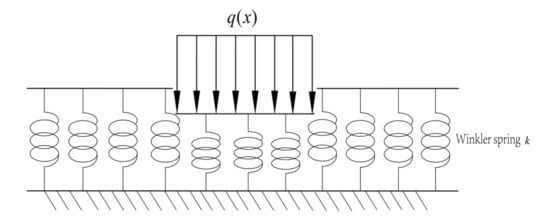
Figure 1.
Winkler foundation model.
In this paper, a new simplified analytical method is proposed to estimate the longitudinal displacement of a shield tunnel subjected to ground surcharge. A two-parameter foundation model, namely the Pasternak foundation model, was established. This model is capable of capturing continuity. In the proposed method, the existing shield tunnel is treated as a continuous Euler–Bernoulli long beam with reduced bending stiffness, resting on a Pasternak foundation. An analytical solution for a shield tunnel subjected to ground surcharge is derived. On the basis of existing research, assuming the continuity of the existing tunnel in the soil and based on an analysis of the tunnel and its interaction with the soil, the Pasternak model in Figure 2 [21] uses the Boussinesq elastic solution to obtain the ground-heaped load distribution in the additional load matrix at the tunnel location. The adjusted coefficient of the bed pressure is used to establish the differential equation of tunnel deformation, and the finite difference method is used to obtain the tunnel longitudinal displacement matrix. The reliability and applicability of the proposed method are verified by comparing field monitoring data, finite element simulation results, and the calculation results of three simplified elastic analysis methods based on different foundation bed coefficients. Based on these results, the parameters of the load–tunnel model are analyzed, and the effects of the buried depth, the size of the load, the relative positions of the load and tunnel, and the relative stiffness of the tunnel soil on the maximum displacement of the existing tunnel are discussed. An empirical formula for the maximum longitudinal displacement of the existing tunnel subjected to surface surcharge is proposed. The contents of this research can provide a basis for the theoretical verification of the deformation response of an existing tunnel subjected to adjacent surface surcharge.
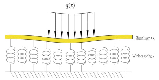
Figure 2.
Pasternak foundation model.
2. Theory of Tunnel Deformation under Surcharge Loading
Ground surcharge will cause a change in the ground stress field, and, as a result, the existing tunnel will undergo settlement deformation. Figure 3 shows the longitudinal deformation diagram of the existing tunnel under the action of ground surcharge loading. In the method proposed in this paper, Euler–Bernoulli beams are used to simulate the bending deformation of existing tunnels. To simplify the calculations, the Euler–Bernoulli beam model assumes that the tunnel section undergoing bending deformation is always perpendicular to the neutral axis, as shown in Figure 4. The shear deformation at the segment joints is ignored, so only the longitudinal bending deformation of the tunnel is considered. The proper application of conservative Euler–Bernoulli beam theory can ensure the safety and stability of the tunnel to a large extent.
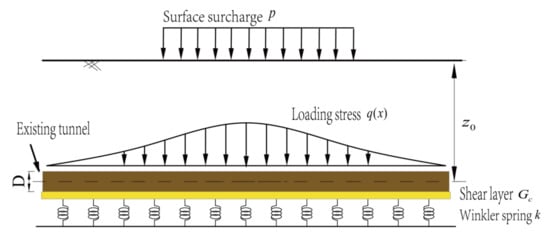
Figure 3.
Schematic diagram of the existing tunnel under surface surcharge.
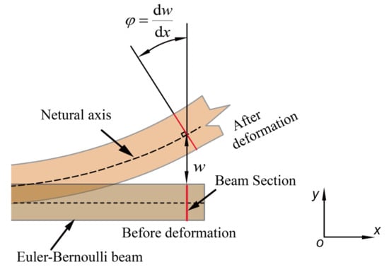
Figure 4.
Deformation characteristics of a Euler–Bernoulli beam.
Then, the existing tunnel is simplified and incorporated into the Pasternak foundation model. As shown in Figure 2, the Pasternak foundation model adds a shear layer to the Winkler foundation model, accounting for the continuous characteristics between soils.
The analytic solution for longitudinal tunnel deformation under the action of ground surcharge is derived with the following assumptions: (a) to simplify calculations, the tunnel is equivalent to an infinitely long Euler–Bernoulli beam; (b) the shear deformation of the layer occurs and does not produce compression deformation; (c) close contact between the soil and tunnel, tunnel deformation, and the contact deformation of soil is consistent; (d) the deformation is independent of the tunnel and the lateral friction force between soil; (e) the deformation is independent of the effects of tunnel and soil compression, such as consolidation settlement and creep.
The theory of longitudinal deformation of an existing tunnel under surface overloading adopts a two-stage analysis method. It is also a common analytical method in studying the response of adjacent construction to an existing tunnel. First, the additional load at the existing tunnel position caused by ground overloading is calculated; then, the calculated external load is applied to the existing tunnel, and the differential equation of longitudinal deformation of the existing tunnel is established. In this method, the longitudinal displacement solution matrix of the tunnel is obtained by using the finite difference method.
2.1. Additional Stresses Caused by Surface Stowage
Figure 4 shows the axis of the existing shield tunnel buried below the ground. Rectangular overloads on the ground above the existing tunnel are shown in Figure 5. The overload length and width are expressed by L and B, respectively. The Boussinesq formula is used to calculate the additional stress caused by ground overloading while ignoring the influence of existing tunnels. Using the Boussinesq formula, the additional longitudinal stress along the axis of the shield tunnel can be obtained:
where is the relative position between the centroid of the uniform ground load and any point on the tunnel axis:
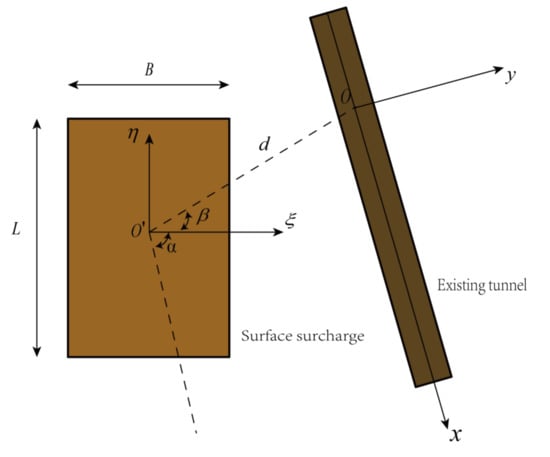
Figure 5.
Coordinates between surface surcharge and the existing tunnel.
In the formula, and are the abscissa and ordinate of the global coordinate system , respectively. is the distance between the tunnel axis and the ground.
To simplify the calculation, a local coordinate system of the tunnel is established as in Figure 1, and the origin of the coordinate system is located at a point on the tunnel axis. In the local coordinate system, the x axis is coincident with the tunnel axis, and the axis is perpendicular to the tunnel axis. The distance between the origin of the global coordinate system and the origin of the local coordinate system is , the angle between the axis of the tunnel and the global coordinate system axis is , and the angle between the connection of the origins of the two coordinate systems and the global coordinate system axis is . Considering the geometric relationship between the two coordinate systems, the transformation expressions of the horizontal and vertical coordinates between any point on the existing tunnel axis and the global coordinate system are obtained:
The external load at the existing tunnel position is obtained by coordinate transformation based on the Boussinesq solution surface surcharge .
2.2. Responses of Tunnels to External Loads
The load–tunnel calculation model is shown in Figure 3. The existing tunnel is equivalent to a continuous Euler–Bernoulli beam placed on a Pasternak foundation. The method assumes that the tunnel is always in contact with the soil and that no slip occurs at the tunnel–soil interface in any direction. In addition, the soil is assumed to be an isotropic elastic material, and the plastic deformation of the soil is not considered. The longitudinal deformation differential equation of the existing shield tunnel based on a Pasternak foundation subjected to surface surcharge stress is as follows:
where is the longitudinal deformation of the tunnel, and is the external load acting on the tunnel. is the tunnel diameter, and is the equivalent bending stiffness of the tunnel.
Equation (4) is a high-order ordinary differential equation, which is not convenient to solve directly. In the proposed approach, the solution is determined using the finite difference method. First, as shown in Figure 6, the finite difference method is carried out for tunnels and other elements. The tunnel is divided into n + 5 units in equal proportion, of which 4 virtual units are located at the two ends of the tunnel (2 at each end), as shown in Figure 2. The unit length is . According to the finite difference principle, the finite difference form of Equation (4) is
where , , , , and are the longitudinal displacements of the tunnel elements , , , , and , respectively, and is the external load acting on the units.
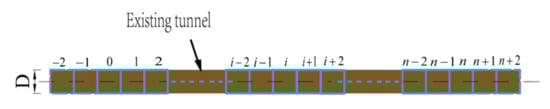
Figure 6.
Finite difference form of the existing tunnel.
For the boundary conditions of the existing tunnel, it is assumed that both ends of the tunnel are free. Then, the bending moment and the shearing force are 0 at both ends, and they are determined, respectively, as follows:
According to the finite difference principle,
The horizontal displacement expressions of the four newly added virtual elements can be obtained with (8a), (8b), (8c), and (8d):
Equation (5) is expressed in matrix form as
After sorting and merging similar items, the following results are obtained:
where is the column vector of the longitudinal displacement of the tunnel, ; is the column vector of the external load in the longitudinal direction caused by basement excavation; and . The expressions of , , and are obtained from the following virtual cell expression:
Let ; then, Equation (11) can be further rewritten:
where is the inverse of .
By solving (1)–(3), the external load at the existing tunnel position caused by the surcharge can be obtained. The longitudinal displacement of the existing tunnel caused by ground surcharge can be obtained by combining Equations (12)–(15).
3. Related Parameters
3.1. Responses of Tunnels to External Loads
In practical engineering, the shield tunnel lining system is composed of segments connected by steel bolts. The longitudinal flexural stiffness of the shield tunnel is clearly lower than that of the continuous lining tunnel due to the existence of intersegment joints. Different researchers have proposed different analytical methods to evaluate the equivalent flexural stiffness of shield tunnels [22,23,24]. Among the existing methods, the Shiba [24] method is more commonly used and widely applied in engineering practice. Figure 7 shows the calculation model of the Shiba method. According to the Shiba theory, the connecting bolt and the lining segment bear tension and pressure, respectively. Under the action of the bending moment, as shown in Figure 7, the upper part of the lining segment bears tension, and the lower part bears pressure. According to the force balance principle, Shiba derives the equivalent bending stiffness formula of the shield tunnel:
where is the elastic stiffness of longitudinal joints of the segment ring, is the elastic modulus of bolts, is the bolt cross-sectional area, is the bolt length, is the longitudinal number of bolts, is the segment width, is the elastic modulus of the segment, and, as shown in Figure 7, is the angle of the neutral axis. is the longitudinal moment of inertia of the segment cross-section, and is the segment cross-sectional area.
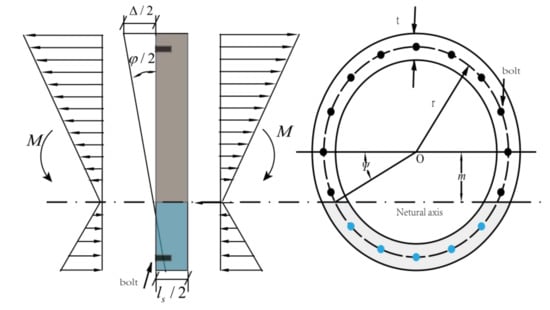
Figure 7.
Deformation and force diagram of the lining segment.
3.2. The Coefficient of the Subgrade Modulus
Different scholars [25,26,27,28,29] have put forward various expressions to calculate the coefficient of the foundation bed . Vesic [29] further modified the existing model and derived the foundation bed coefficient :
where is the elastic modulus of the soil, is the tunnel diameter, is the Poisson’s ratio of soil, and is the bending stiffness of the beam—that is, the equivalent bending stiffness of the tunnel .
In practice, the premise of the derivation of the expression is that the beam rests on the ground. Shield tunnels are generally buried below the surface, and the relative stiffness of the soil is highly sensitive to the embedded depth of the tunnel. Thus, Vesic coefficients that are obtained under the assumption that they are placed at ground level can lead to misleading results for the tunnel (or pipeline) response to external construction [26,27]. Attewell [26] et al. suggested that the value should be 2 times for a pipeline or tunnel with a certain embedded depth; that is,
where is the coefficient of the foundation bed of a beam buried at a certain depth below the surface.
Based on the superposition principle and Fourier integral transform, Yu [25] obtained the expression of the foundation bed coefficient of an infinitely long beam located at the surface of an elastic half-space and an infinite buried depth:
with
where is the tunnel diameter, and h is the buried depth of the tunnel.
Based on the research results of Vesic, Attewell, and Yu, this paper puts forward an expression of the foundation bed coefficient for a given embedded depth and considers the tunnel excavation size:
3.3. The Coefficient of the Subgrade Modulus
The stiffness coefficient of the shear layer is an important parameter in Pasternak’s two-parameter model. Different methods for evaluating have been proposed [30,31]. In this paper, the calculation formula proposed by Tanahashi [31] is adopted:
where is the thickness of the shear layer, which is 2.5 times . The equivalent bending stiffness of the tunnel can be determined from the calculation formula given by Shiba et al. [24].
4. Case Validation
4.1. Finite Element Simulation
Finite element simulation software was used to verify the feasibility of the proposed method. The size of the model in Figure 8 is 200 (length) × 100 (width) × 50 (height), which eliminates the boundary effect. In this paper, the existing tunnel has a diameter of 6.2 m and a tunnel axis that is 16.9 m away from the ground. The mechanical properties of the simulated stratum and soil are shown in Table 1, and the existing tunnel’s structural parameters are shown in Table 2. In the uniformly distributed load model, the ground load with a size of 40 m × 20 m is 40 MPa. The soil in the finite element model is a layer of common soft soil. The constitutive model of soil strengthened with small strain stiffness is used to simulate the mechanical behavior of soft clay. The failure of the soil is defined by the Moor–Coulomb failure criterion. The equivalent bending stiffness of the tunnel is 7.8 × 10⁴ MN m2.
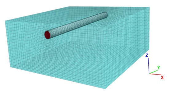
Figure 8.
Finite element model of the existing tunnel.

Table 1.
Physical–mechanical parameters of soil.
Table 2.
Tunnel parameters of Shanghai Metro Line 9.
Figure 9 compares the results of the proposed analytical method with those of the finite element simulation of the longitudinal displacement of the existing tunnel subjected to surface surcharge. As can be seen from the figure, the analytical solution obtained by using the revised foundation bed coefficient is slightly larger than the finite element simulation result, which may be because the soil is continuous in the Pasternak foundation; this deviation is acceptable in practical engineering. Moreover, the existing tunnel settlement curve obtained from the analytical solution is in good agreement with the simulation result.
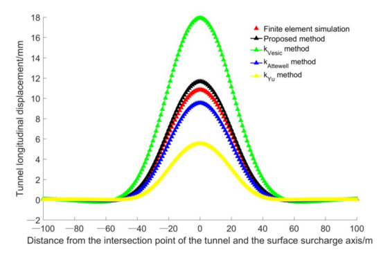
Figure 9.
Comparison of the analytical solution and finite element simulation.
The results of the other three simplified analytical elastic methods show that the prediction results for the method based on the Vesic foundation bed coefficient are clearly higher than the finite element simulation results. Attewell’s and Yu’s foundation bed coefficients underestimate the tunnel settlement, which indicates that the tunnel settlement is inversely proportional to the soil foundation bed coefficient. Although the tunnel settlement calculated by the Yu foundation bed coefficient is close to the simulation results, this method is bound to underestimate the prediction results, which poses a risk to the safety of the tunnel structure; therefore, its use is not recommended.
4.2. The Case of Earth Piling in the Middle Zhongjiu Section of Shanghai Subway Line 9
The relative positions of the middle Zhongjiu section of Shanghai Metro Line 9 and Xiaolai River directly above are shown in Figure 10 [32]. The width of Xiaolai River is 24 m, the backfill height is 4.5 m, and the backfill weight is = 17 kN/m3. The net distance between the bottom of the river and the tunnel vault of Metro Line 9 is 5 m, and the tunnel structural parameters are shown in Table 2. The segment parameters of the Zhongjiu Interval Tunnel in Line 9 are shown in Table 2. With these values, the equivalent bending stiffness of the tunnel is 7.8 × 10⁴ MN m2. Field data parameters are given by Fan and shown in Table 3. The soil elastic modulus is 15 MPa, and Poisson’s ratio is 0.33. As shown in Figure 10, the field monitoring results show that the maximum longitudinal deformation of the shield tunnel is 28 mm, which decreases toward both sides of the tunnel along the intersection of the river axis and the tunnel axis. The area with the larger influence is directly under the river channel.
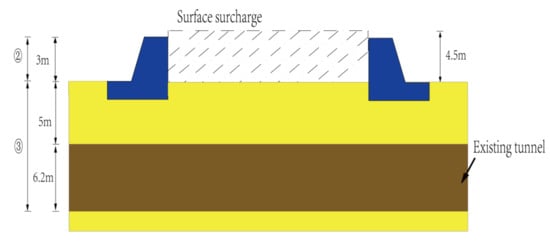
Figure 10.
Relative locations of Shanghai Metro Line 9 (Zhongjiu Section) and Xiaolai Gang River.
Table 3.
Physical and mechanical parameters of soil.
Figure 11 compares the prediction results and field monitoring data between the analytical method in this paper and the three elastic simplified analytical methods. The prediction results of the method based on the Vesic [29] foundation coefficient are clearly higher than the field monitoring results. This indicates that the Vesic foundation reaction modulus expression indeed underestimates the relative stiffness of the tunnel soil and thus overestimates the tunnel settlement. However, the elastic simplified analysis method based on the Yu foundation bed coefficient expression greatly underestimates the tunnel settlement. Yu’s method overestimates the relative stiffness of tunnel soil, which results in a large error in tunnel settlement. Similarly, the method based on the foundation bed coefficient of Attewell [26] also underestimates the tunnel settlement. As shown in Figure 11, the method presented in this paper can better predict the longitudinal displacement of the tunnel, and the results show that it is suitable for predicting the longitudinal deformation of the existing tunnel caused by surface overloading.
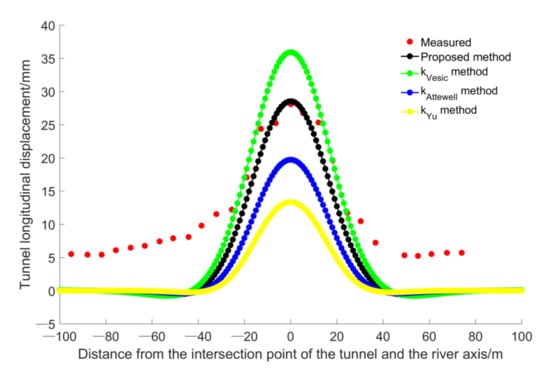
Figure 11.
Comparison between the measured and computed results for the Zhongjiu section of Shanghai Metro Line 9.
5. Parameter Analysis
The feasibility of the proposed method was verified by comparing it with finite element simulation, which analyzes the influence of surface surcharge on the existing operating tunnel. A parameterized analysis was adopted in this experiment to further understand the influence of various factors in the surcharge load–soil–tunnel model on the existing tunnel. The main influencing factors include the relative positions of the tunnel and the load, the geometric size of the load, and the relative stiffness of the tunnel and soil. The relationship between the tunnel axis and the position of the load in the load–tunnel model is shown in Figure 12. The shape of the load is rectangular, and the length and width are 48 m and 24 m, respectively. The existing tunnel is assumed to have an outer diameter of 6.2 m, an inner diameter of 5.5 m, an annulus width of 1.2 m, and an axis buried depth of = 15 m. The spacing between the surface surcharge center and the tunnel axis d is 0. Poisson’s ratio of the soil in the stratum in which the tunnel is located is 0.35, and the elastic modulus is 15 MPa. The calculated equivalent bending stiffness of the tunnel is 7.8 × 10⁴ MN m2, and the structural parameters of the tunnel are shown in Table 2.
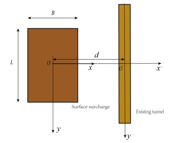
Figure 12.
Relative positions of the tunnel and surface surcharge.
5.1. Tunnel–Surcharge Spacing
Assuming that the parameters of the new and existing tunnel models remain unchanged, five curves of tunnel buried depth and maximum longitudinal displacement were generated for different load–tunnel spacing . Figure 13 shows the variation curve of the maximum longitudinal displacement for increasing tunnel buried depths and different load–tunnel centerline spacing . As shown in the figure, for a given spacing , the maximum longitudinal displacement of the tunnel decreases gradually with a varying slope as the tunnel buried depth increases. The maximum longitudinal displacement of the tunnel is different for different tunnel–load spacing . When = 0, the tunnel is located at the center of the surcharge, and the external load disturbance is the most significant. Therefore, the maximum longitudinal displacement of the existing tunnel caused by the surcharge is large, and it increases rapidly as the buried depth decreases. As can be seen from the figure, as the tunnel buried depth increases, the maximum displacement change rate of the tunnel gradually decreases for different tunnel–surcharge spacing . The reason is that the external load corresponding to the surcharge load has little influence on the tunnel with a small embedded depth.
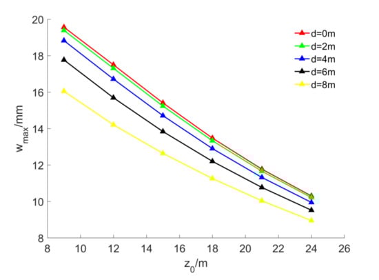
Figure 13.
Influence of tunnel burial depth on the maximum longitudinal displacement of the existing tunnel.
5.2. Tunnel Buried Depth
Similarly, Figure 14 shows the curve of the maximum longitudinal displacement of the tunnel and the tunnel–load spacing . For different buried tunnel depths , the maximum longitudinal displacement of the tunnel changes at different rates as the surface-to-tunnel spacing increases, and the rate of change gradually increases. However, as the tunnel buried depth increases, the change becomes less pronounced, indicating that the existing tunnel is relatively less affected by overloading.
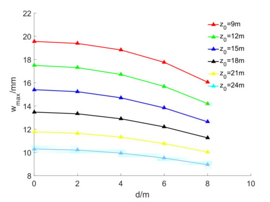
Figure 14.
Influence of surcharge load and tunnel spacing on maximum longitudinal displacement of the existing tunnel.
5.3. Tunnel–Surcharge Angle
In the following analysis, the tunnel model in the previous analysis remains the same, and only the tunnel–surcharge included angle is changed. Figure 15 shows the relationship between the tunnel–surcharge angle and the maximum longitudinal displacement of the existing tunnel at different tunnel burial depths, where the tunnel–surcharge angle ranges from to . As shown in Figure 15, for different tunnel burial depths, the maximum longitudinal displacement of the existing tunnel follows an “S-shaped curve” trend that decreases as the tunnel–surcharge angle increases. For the same tunnel–surcharge angle , as the tunnel burial depth increases, the maximum longitudinal displacement of the existing tunnel decreases proportionally, indicating that the influence of the surcharge on the tunnel is linearly related to the burial depth of the existing tunnel. Furthermore, when the tunnel depth = 9 m, the maximum displacement of the existing tunnel caused by overloading is close to the standard allowable value of . When the buried depth of the tunnel = 24 m, the maximum longitudinal displacement of the tunnel is approximately 10 mm, indicating that the tunnel is still greatly affected by the overload. Therefore, changing the depth of the tunnel cannot completely remove the effect of the overload on the existing tunnel.
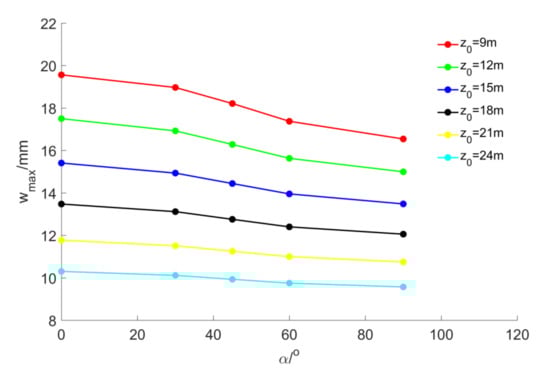
Figure 15.
Influence of tunnel–surcharge angle on the maximum longitudinal displacement of the existing tunnels.
5.4. Surface Surcharge Size
Based on the model parameters of new and existing tunnels, only the tunnel–load spacing is changed in the following analysis. Figure 16 shows the relationship between the maximum longitudinal displacement of the tunnel and the length of the surcharge. As shown in the figure, for a surcharge with a fixed width and the same surcharge and tunnel spacing, the maximum longitudinal displacement of the tunnel increases gradually as the length of the surcharge increases, but the growth rate gradually decreases. As the surcharge length increases from 8 m to 72 m, the maximum longitudinal displacement of the tunnel increases significantly. When the surcharge length increases from 72 m to 96 m, the increase in the maximum displacement is only 1%. For the same tunnel, when the length of the surcharge is greater than 72 m, the maximum displacement of the tunnel tends to be stable for different surcharge spacing . As the tunnel–load spacing increases, the maximum longitudinal displacement of the tunnel decreases considerably. The analysis shows that the maximum displacement of the existing tunnel is affected by the space between the overload and tunnel.
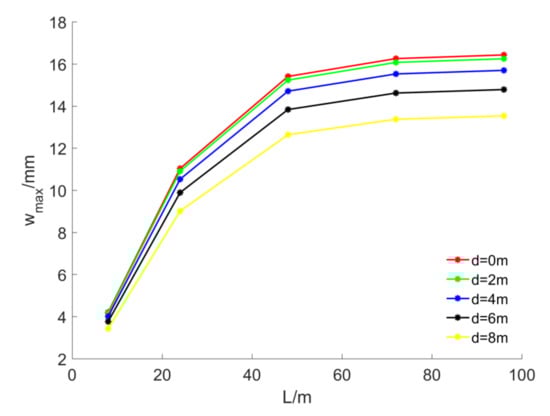
Figure 16.
Influence of surface surcharge length L on the maximum displacement of the existing tunnel.
Similarly, Figure 17 shows the relationship between the maximum displacement of the tunnel and the width of the load for different tunnel–load spacing and a constant load length. As the surface surcharge width increases from 8 m to 72 m, the maximum displacement of the tunnel gradually increases, and the change rate gradually decreases. As the load width increases to 96 m, the maximum displacement of the tunnel gradually decreases. The increase in maximum displacement tends to be stable when the load width is greater than 72 m. The values of maximum longitudinal displacement of the tunnel for different spacing converge toward the same value, and the rate of change tends towards 0 as the width increases. Therefore, the maximum longitudinal displacement of the tunnel is no longer affected by the tunnel–load spacing as the width of the load increases.
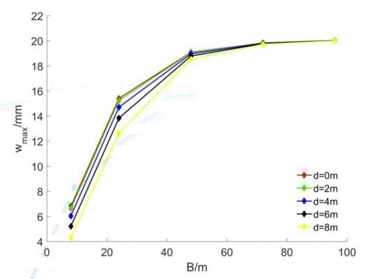
Figure 17.
Influence of surface surcharge width B on the maximum displacement of the existing tunnel.
According to the above analysis, the maximum longitudinal displacement of the tunnel is related to the buried depth of the tunnel , the tunnel–surcharge spacing , the surcharge size , and the tunnel–surcharge angle . Next, previously published cases of the response of an existing tunnel to the overload are analyzed to verify the reliability and practicability of the prediction formula for the maximum longitudinal displacement of the tunnel.
6. Empirical Formula
6.1. Empirical Formula for the Maximum Longitudinal Displacement of the Tunnel
Based on the above analysis, the relationship between the maximum longitudinal displacement of the tunnel, the buried depth of the shield tunnel , and the distance between the tunnel and the surcharge load spacing is approximately nonlinearly decreasing. Furthermore, the maximum longitudinal displacement of the tunnel has a decreasing “S-shaped curve” relationship with the angle between the load axis and the tunnel axis, and it has a polynomial increasing relationship with the length L and the width of the load. On this basis, a formula with simplified parameters for predicting the maximum longitudinal displacement of the tunnel is established as follows:
where , , , , , , , , , , , and are formula coefficients, and . is the maximum longitudinal displacement of the tunnel. To unify the prediction formula calculation, the tunnel angle is converted to radians in the calculation. The formula coefficients of the parameter prediction equation were calculated, and the results are shown in Table 4.
Table 4.
Equation (25) parameters.
6.2. Verification of the Empirical Formula for Maximum Longitudinal Displacement
To further verify the applicability of the formula, several cases that describe the effects of surcharge load on the longitudinal deformation of existing tunnels under similar site conditions were collected from the published literature. Table 5 lists parameters such as tunnel–load spacing, included angle, and tunnel buried depth. Table 5 shows cases collected from the published literature. It clear from Table 5 that the prediction results of Equation (25) are consistent with published data from the literature, and most of the overall deviations are within 20%, which falls within the acceptable range.
Table 5.
Case (numerical simulation) values.
7. Conclusions
This paper presents a theoretical method for efficiently predicting the longitudinal deformation of existing tunnels under overloading. The following conclusions can be drawn:
(1) The reliability and applicability of the proposed method were verified by comparing the results of finite element simulations of field test data and the calculation results of three simplified elastic analysis methods based on different foundation bed coefficients.
(2) Based on the Boussinesq elastic solution, the additional load on the existing tunnel was obtained. A Euler–Bernoulli beam on a Pasternak foundation was used as a simplified model to analyze the stress of the existing tunnel. Using the corrected reaction coefficient of the foundation bed, the differential equation of tunnel deformation was established, and the longitudinal displacement matrix of the tunnel was calculated using the finite difference method.
(3) The parameters of the surcharge load–tunnel model were analyzed, and the effects of the buried depth of the tunnel, the size of the surcharge load, the relative positions of the tunnel and surcharge, and the relative stiffness of the tunnel soil on the maximum displacement of the existing tunnel were calculated. An empirical formula for the maximum longitudinal displacement of the existing tunnel subjected to surface surcharge is proposed. The contents of this research can provide a basis for the theoretical verification of the deformation response of an existing tunnel subjected to adjacent surface surcharge. It can be used to quickly predict the response of a tunnel in the initial design stage.
Author Contributions
Writing—original draft, Z.W.; Writing—review and editing, Y.J. All authors have read and agreed to the published version of the manuscript.
Funding
This research was funded by key projects of the Coal Joint Fund of the National Natural Science Foundation of China (U1261212). This financial support is gratefully acknowledged.
Institutional Review Board Statement
Not applicable.
Informed Consent Statement
Informed consent was obtained from all subjects involved in the study.
Conflicts of Interest
The authors declare no conflict of interest.
References
- Tan, X.; Zhang, H.; Zhang, G. An Improved method for predicting the greenfield stratum movements caused by shield tunnel construction. Appl. Sci. 2019, 9, 4522. [Google Scholar] [CrossRef]
- Li, S.; Li, P.; Zhang, M. Influence of approaching excavation on adjacent segments for twin tunnels. Appl. Sci. 2019, 10, 98. [Google Scholar] [CrossRef]
- Zhao, W.; Jia, P.; Zhu, L. Analysis of the additional stress and ground settlement induced by the construction of double-o-tube shield tunnels in sandy soils. Appl. Sci. 2019, 9, 1399. [Google Scholar] [CrossRef]
- Zhu, Y.; Chen, L.; Zhang, H. Quantitative analysis of soil displacement induced by ground loss and shield machine mechanical effect in metro tunnel construction. Appl. Sci. 2019, 9, 3028. [Google Scholar] [CrossRef]
- Helali, K.; Voth, M.; Bekheet, W. Development of roughness deterioration models for national park service network. Trans. Res. Board Meet. 2006, 6, 2731. [Google Scholar]
- Li, P.; Chen, K.; Wang, F. An upper-bound analytical model of blow-out for a shallow tunnel in sand considering the partial failure within the face. Tunn. Undergr. Space Technol. 2019, 91, 102989. [Google Scholar] [CrossRef]
- Zhang, Z.X.; Liu, C.; Huang, X.; Kwok, C.Y.; Teng, L. Three-dimensional finite-element analysis on ground responses during twin-tunnel construction using the urup method. Tunn. Undergr. Space Technol. Res. 2016, 58, 133–146. [Google Scholar] [CrossRef]
- Liu, D.; Zhang, D.; Fang, Q. Displacement characteristics of shallow-buried large-section loess tunnel with different types of pre-supports: A case study of new badaling tunnel. Appl. Sci. 2019, 10, 195. [Google Scholar] [CrossRef]
- Naseem, A.; Kashif, M.; Iqbal, N. seismic behavior of triple tunnel complex in soft soil subjected to transverse shaking. Appl. Sci. 2020, 10, 334. [Google Scholar] [CrossRef]
- Wang, R.; Zhang, D. Mechanism of transverse deformation and assessment index for shield tunnels in soft clay under surface surcharge. Chin. Geotechnol. Eng. 2013, 35, 1092–1101. [Google Scholar]
- Ke, Z.; Liang, R.; Tong, Z.; Yue, T.; Guo, Y. Simplified analytical solution for nonlinear longitudinal deformation of shield tunnels under surface surcharge. Chin. Geotechnol. Eng. 2019, 41, 245–248. [Google Scholar]
- Shao, H.; Huang, H.; Zhang, D.; Wang, R. Case study on repair work for excessively deformed shield tunnel under accidental surface surcharge in soft clay. Chin. Geotech. Eng. 2016, 38, 1036–1043. [Google Scholar]
- Zhang, M.; Zhou, S.; Huang, D.; Wang, X.; Liu, H. Analysis of influence of surface surcharge on subway shield tunnel under. Rock Soil Mech. 2016, 37, 2271–2278. [Google Scholar]
- Dai, H.; Chen, R.; Chen, Y. Study on effect of construction loads on longitudinal deformation of adjacent metro tunnels. Chin. Geotechnol. Eng. 2006, 28, 312–316. [Google Scholar]
- Wu, Q.; Du, S. Model test on influence of ground heaped load on existing shield tunnel structure. Chin. Undergr. Space Eng. 2014, 10, 57–66. [Google Scholar]
- Gao, J.; Huang, B.; Zhang, W.; Chen, J. Study of calculation method for vertical displacement of crossed tunnels under surface surcharge loading. Tuning. Construct. 2018, 38, 818–823. [Google Scholar]
- Yamamoto, K.; Lyamin, A.; Wilson, D. Stability of dual circular tunnels in cohesive-frictional soil subjected to surcharge loading. Comput. Geotech. 2013, 50, 41–54. [Google Scholar] [CrossRef]
- Lu, P.; Wang, M.; Yang, J. Influences of surface surcharge on the deformation of shield tunnel in soft ground area. Build. Struct. 2019, 49, 999–1003. [Google Scholar]
- Li, J.; Qian, J.; Ru, Z.; Gao, J.; Huang, L. Three-dimensional method for response of embedded pipelines to earthfill load. Chin. Geotechnol. Eng. 2015, 37, 65–69. [Google Scholar]
- Kang, C.; Mei, G.; Liang, R.; Wu, W.; Fang, Y.; Ke, Z. Analysis of the longitudinal deformation of existing shield tunnel induced by temporary surface surcharge. Rock Soil Mech. 2018, 39, 4605–4616. [Google Scholar]
- Liang, R. Simplified analytical method for evaluating the effects of overcrossing tunnelling on existing shield tunnels using the nonlinear pasternak foundation model. Soils Found. 2019, 59. [Google Scholar] [CrossRef]
- Shen, P. Analysis of shearing effect on tunnel induced by load transfer along longitudinal direction. Tunn. Undergr. Space Technol. 2008, 23, 421–430. [Google Scholar]
- Ye, F.; He, C.; Zhu, H.; Sun, H. Longitudinal equivalent rigidity analysis of shield tunnel considering transverse characteristics. Chin. Geotech. Eng. 2011, 33, 1870–1876. [Google Scholar]
- Shiba, Y.; Kawashima, K.; Obinata, N. An evaluation method of longitudinal stiffness of shield tunnel linings for application to seismic response analyses. Doboku Gakkai Ronbunshu 1988, 1988, 319–327. [Google Scholar] [CrossRef]
- Jian, Y.; Zhang, C.; Huang, M. Soil–pipe interaction due to tunnelling: Assessment of winkler modulus for underground pipelines. Comput. Geotechnol. 2013, 50, 17–28. [Google Scholar]
- Attewell, P.; Yeats, J.; Selby, A. Soil movements induced by tunnelling and their effects on pipelines and structures. Int. J. Rock Mech. Min. Sci. Geomech. Abstr. 1987, 24, 163. [Google Scholar]
- Terzaghi, K. Evalution of conefficients of subgrade reaction. Géotechnique 1955, 5, 297–326. [Google Scholar] [CrossRef]
- Mair, R.; Soga, K.; Klar, A. Soil-pipe Interaction due to tunnelling: Comparison between winkler and elastic continuum solutions. Géotechnique 2005, 55, 461–466. [Google Scholar]
- Vesic, A. Bending of beams resting on isotropic elastic solid. J. Eng. Mech. Div. 1961, 87, 35–53. [Google Scholar] [CrossRef]
- Kerr, A. On the determination of foundation model parameters. J. Geotechnol. Eng. 2014, 111, 1334–1340. [Google Scholar]
- Tanahashi, H. Formulas for an Infinitely Long Bernoulli-euler Beam on the Pasternak Model. J. Jpn. Geotechnnol. Soc. 2004, 44, 109–118. [Google Scholar] [CrossRef]
- Fan, Y.; Guo, X.; Deng, Z.; Xu, Y. Deformation analysis of shield tunnel with loading and unloading above. Construct. Technol. 2014, 43, 107–109. [Google Scholar]
- Li, C.; Wang, G.; Zhao, K.; Zhu, C. Vertical mechanical behavior on shield tunnel under loads on ground surface. J. Jilin Univ. 2011, 41, 180–184. [Google Scholar]
- Qu, J.; Pan, R.; Tang, R. Study on longitudinal deformation of tunnels based on foundationbeam of double elastic. J. Water Resour. Water Eng. 2016, 27, 190–194. [Google Scholar]
Publisher’s Note: MDPI stays neutral with regard to jurisdictional claims in published maps and institutional affiliations. |
© 2021 by the authors. Licensee MDPI, Basel, Switzerland. This article is an open access article distributed under the terms and conditions of the Creative Commons Attribution (CC BY) license (https://creativecommons.org/licenses/by/4.0/).