Abstract
Dragonfly wings have many excellent functions, such as superhydrophobic, fatigue resistance, anti-reflection, etc. However, there are few reports on the low noise flight of dragonfly wings. For this reason, the microgeometry of dragonfly wings was studied in this paper to reveal the mechanism of low-noise flight of dragonfly leading veins. The micromorphology of dragonfly wings was observed by scanning electron microscopy. It was found that the leading-edge veins of dragonfly wings have a triangular prism-like serrated structure, which has been proven to have the effect of improving aeroacoustics. According to the principle of scale law of flying organisms, a bionic model with the leading-edge microstructure of dragonfly’s front wing was established, and computational fluid dynamics (CFD) analysis of serration bionic microstructure was carried out. The effects of geometric parameters, such as height, width and overall amplification factor of microstructure on aeroacoustics were obtained. The distribution of pressure fluctuation on the surface of the bionic wing was also analyzed in this paper. It was found that the serrated microstructure can significantly suppress the noise generation in the mid-frequency band. Finally, wind tunnel tests were simulated using a designed low-noise rotating test platform. The test results confirmed that the serration microstructure has certain noise-reduction characteristics.
1. Introduction
The dragonfly has been attracting much interest due to its excellent characteristics, such as low-noise high mobility flight [1]. As the most important organ to support silent flight, the dragonfly wing is becoming a research hotspot in many fields. It has been found that the coupled effects of wing shape, configuration, structure, material and other factors make dragonflies have multiple functions of vibration reduction, noise reduction, self-cleaning and fatigue resistance [1]. However, the study in anti-vibration and noise-reduction characteristics of dragonfly wings mainly focused on the pterostigma of dragonfly wings, and the low-noise flight characteristics of dragonfly wings are rarely reported in detail.
The flying noise of dragonflies is very gentle, which is not only related to the wing pterostigma but also to the veins of dragonfly wings and the microstructure on their wings. According to hydrodynamic analysis, when the solid surface is in an unstable and nonuniform incident flow, aerodynamic noise will be generated. When a dragonfly glides, the wing and airflow have a similar interaction relationship. Therefore, this noise generation mechanism can be analogous to the noise formation of a fixed-wing in an aircraft. Generally, the noise can be divided into six categories, and each source produces the scattering noise of the wing independently. The six types of noise sources are inflow turbulence, turbulent boundary layer trailing edge interaction, separating flow, laminar boundary layer vortex shedding, trailing edge bluntness vortex shedding and tip vortex formation [2]. Wind tunnel tests confirmed that the trailing edge noise dominated when the incident airflow was laminar and that the leading edge noise became the main source of noise and concealed the trailing edge noise when the incident airflow was severe turbulence [3]. In the process of flying, dragonflies will inevitably be affected by natural wind; that is, the incoming airflow is turbulent, but the turbulence intensity is not high. It can be concluded that the noise source is composed of leading-edge noise and its self-noise. The flying noise of dragonflies is very small. This paper infers that it is related to the microstructure of the leading edge of dragonfly wings, which can effectively reduce the leading-edge noise and the self-noise of the wings and then effectively reduce the overall noise of the wings.
Noise reduction characteristics of the surface microstructure of flying biological wings have been studied extensively. The quiet flight characteristics of the long-eared owl are closely related to the special morphological structure of its wings. The circular-arc toothed structure of the leading edge of the wing has a function similar to an eddy current generator. It delays the separation of the airflow boundary layer on the wing surface, makes the airflow adhere to the upper surface of the entire leading-edge boundary layer of the wing, and makes the air eddy flow passing through the wing edge change from larger air eddy to smaller eddy flow, thus reducing the aerodynamic eddy noise generated by flight [4]. Generally, the incident turbulence amplifies the pressure fluctuation near the leading edge of the wing, and the pressure fluctuation scattering on the wing will become broadband noise [5]. Some studies have shown that the front serration structure can significantly reduce the pressure fluctuation in the front and middle regions of the serration structure, thereby reducing the broadband noise level [6]. The experimental results show that the noise-reduction effect of the serrated leading edge is not ideal in the low-frequency range, but it has an obvious noise-reduction effect in the middle frequency range (500 Hz to 8 kHz). Moreover, the height of the serrated leading edge is an important parameter affecting the noise-reduction effect of the flat wing [7]. From the above analysis, it can be seen that under certain conditions, the leading-edge sawtooth structure can effectively reduce the leading edge noise caused by the interaction of incident turbulence and the leading edge of the wing, as well as the wing self-noise caused by the pressure fluctuation and vortices on the upper surface of the wing.
In the course of studying the flight noise of flapping wing air vehicles, the low-noise flight characteristics of dragonfly wings are found. Through observation, it is found that the leading edge of dragonfly wings has unique microstructure distribution, and similar microstructure have been proven to have the effect of reducing the leading-edge noise. Based on this, this paper mainly studies the morphology of dragonfly wing leading edge and its noise-reduction mechanism and establishes a bionic model. The geometric characteristics of the optimized model are simulated and analyzed to prepare the microstructural samples, and the experimental tests are carried out to reduce the noise of the aircraft.
The following parts of this paper are arranged as follows: The second part is mainly about observing the microstructure of dragonfly wings and building bionic models. In the third part, the computational fluid dynamics (CFD) simulation analysis of microstructure is carried out, and the microstructural model is optimized. In the fourth part, the microstructure samples are processed and tested. Finally, the noise-reduction characteristics of the dragonfly wing microstructure are summarized and analyzed.
2. Bionic Modeling of Dragonfly Wing Microstructure
2.1. Observation of the Leading-Edge Microstructure
The bionic prototype used in this paper was the Pantala flavescens fabricius, the most common dragonfly in northern China. To explore more details of the morphology of the dragonfly wing’s leading-edge microstructure from root to tip, three different positions were selected to observe the target shown in Figure 1. Based on the study of scanning electron microscopy on different leading-edge positions, it was found that the profile of the whole leading edge looks like a triangular prism, and every edge of the triangular prism had a series of protuberances along the edge direction. These protuberances were strongly identical to each other in shape, and every protuberance resembles a slant triangular pyramid. These triangular pyramid-like structures distributed in three edges of the leading edge form the serration microstructure. As seen in Figure 1, serration microstructures at the bottom of the leading edge were larger than the upper ones in size. Moreover, they both decrease gradually from the wing root to the tip in width along the spanwise direction. As a result, further studies need to focus on quantitative microstructure-related parameters. The regular triangle edge height E of the leading-edge section, thickness T, height H and upper width W1, lower width W2 of triangular pyramid-like microstructure were obtained by SEM observation shown in Table 1.
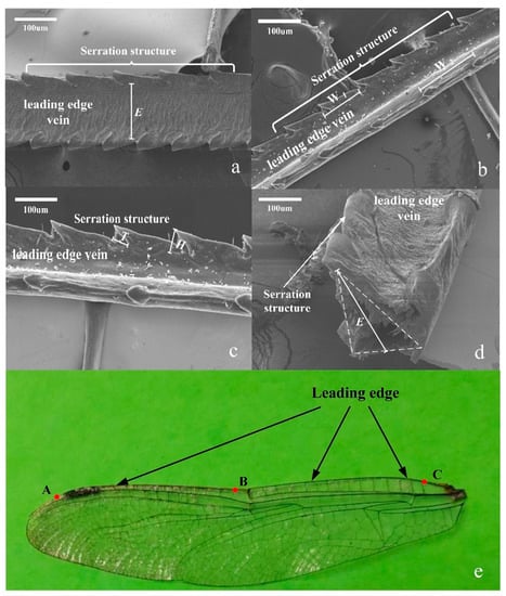
Figure 1.
SEM images and sample of dragonfly’s front wing leading edge. (a) Serration structure of A area leading edge. (b) Serration structure of B area leading edge. (c) Serration structure of C area leading edge. (d) Cross-section of the leading edge. (e) Dragonfly’s front wing.

Table 1.
Parameters of leading-edge wing vein microstructure (μm).
2.2. Modeling and Design of Bionic Wing and Leading-Edge Microstructure
In order to analyze the aerodynamic characteristics of the leading-edge microstructure conveniently, a bionic wing was designed as the carrier of the bionic microstructure based on the dragonfly’s front wing. The bionic wing was designed according to the principle of scale law [8,9,10,11,12]. The wingspan L, wing area S and aspect ratio AR of the bionic wings correspond to the mass of flying objects m. In this paper, the homemade flapping-wing micro air vehicle was chosen as the carrier in the design, and its mass m was about 25 g. The calculation equation is as follows:
According to the above equations, it can be calculated that: L = 0.278 m, S = 0.0112 m, AR = 6.86. Generally speaking, a wing with a larger area means a larger lift force. A small aspect ratio can improve agility and maneuverability, while a large aspect ratio can improve gliding ability [13]. Small changes to the wing plane design would have a great influence on the aerodynamic force. There was some modification to the wing shape design that the wingtip area was enlarged for better aerodynamic forces [14]. The detailed size of the modified wing in this paper was modified as follows: the half-wing span L/2 = 14 cm, the wing area S = 126 cm2, aspect ratio AR = 6.22. The dragonfly’s forewing specimen and its bionic wing model are shown in Figure 2.
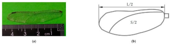
Figure 2.
The morphology of dragonfly’s forewing and its bionic model. (a) Dragonfly front wing; (b) bionic front wing model and size.
The microstructure near the leading edge fin was modeled as shown in Figure 3, and the parameters of the microstructure are shown in Table 2.
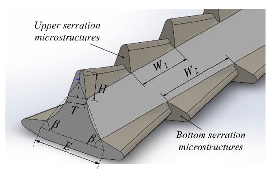
Figure 3.
Biomimetic leading-edge microstructure model of a dragonfly wing.
Table 2.
Bionic serration microstructure parameters ().
3. Aerodynamic Noise Analysis and Optimization of a Bionic Model of Dragonfly Wings’ Leading-Edge Microstructure
The characteristic dimension parameters of the bionic serrated shape are mainly width W1 (W2) and height H. In this part, XFlow is used to analyze the aeroacoustic characteristics of the bionic serrated microstructure. The effects of sawtooth structure amplification factor, length W1, length W2 and height H on wing noise level were investigated. In the simulation analysis, the ambient temperature was set to 20 °C, and the wind speed was set to 4.7 m/s. Under this condition, the Reynolds number was more than 4000, so the motion of the fluid was turbulent, but the turbulence intensity was not high. Therefore, the aerodynamic noise generated by the bionic wings was determined by the leading edge noise and the self-noise of eliminating the trailing edge noise. However, under this simulation condition, the leading-edge noise generated by the interaction between the incident flow and the leading edge of the wing was the main noise source. Therefore, the probe for measuring the noise in the simulation was placed above the center of the leading edge of the wing to collect the pressure fluctuation. In order to explore the influence more accurately of leading-edge microstructure on the aerodynamic noise of the bionic wings, it was necessary to filter the trailing edge noise generated by the bionic wings. Therefore, the overall sound pressure level (OASPL) was used to represent the noise generated by the bionic wings with different leading-edge microstructures. The definition of the overall sound pressure level is as follows:
The value of is the sound pressure level between the frequency ranges () of the center of the 1/3 octave frequency band. The frequency range () chosen for the analysis in the overall sound pressure level was set from (100 Hz) to (10 kHz). The basis for selection is as follows: The decision on was due to the consideration of the initial frequency of the sound level meter. Moreover, the noise-reduction effect of serrated microstructure in low-frequency regions was not obvious. The measurement of the OASPL from the beginning of (100 Hz) had little effect on the comparison of that produced by different leading-edge microstructure. Moreover, was decided upon the exclusion of the possible influences by the airfoil self-noise from the trailing edge [6]. The OASPL calculated by this method could more accurately reflect the influence of the leading-edge microstructure on the aerodynamic noise of the bionic wing.
3.1. Influence of the Overall Size of the Leading-Edge Microstructure on the Noise-Reduction Effect
In this section, the overall size of the dragonfly wing leading-edge microstructure is explored. In the analysis of the leading-edge noise caused by the interaction between the incident turbulence and the leading edge of the wing, the bionic wing was simplified to some extent. This meant a rectangular plate with a length of 140 mm, a width of 45 mm and a thickness of 0.09 mm was chosen as the basic wing.
The bionic wing was based on the basic wing with these serration microstructures. The OASPL between the basic wing and the bionic wing was compared. First, the leading-edge microstructure model of dragonfly wings was established in 1:1 ratio and then enlarged by 1 to 10 times and numbered as wing 1 to wing 10.
The OASPL values of these wings in XFlow noise simulation are shown in Table 3. As seen in Table 3, the OASPL of the bionic wing 1 to wing 6 was obviously lower than the basic one, which means a certain noise-reduction effect induced by microstructure existed. While the OASPL of wing 7 to wing 10 was higher in numerical number than the basic wing. This shows that the leading-edge microstructure of the bionic wings had an influence on the noise-reduction effect, but different microstructure sizes would bring different acoustics effects. When bionic microstructure enlarged to a certain extent, it produced more noise with the increase of the overall size.
Table 3.
Overall sound pressure level of different bionic wings.
Overall sound-pressure-level reduction () was used studied to compare the noise-reduction effects of different bionic airfoils. Subtracting the from the gives the overall sound-pressure-level reduction , the expression equation is as follows:
where and are the OASPL of the basic wing and bionic wing with serration microstructure, respectively. Equation (5) can be used to calculate the OASPL reduction of different bionic airfoils compared with the basic one. The ∆OASPL value of wing 1 to wing 6 is shown in Table 4. As can be seen from Table 4, the maximum ∆OASPL 12.5 decibels was obtained from wing 4. The overall size range of the bionic leading-edge microstructure with the noise-reduction effect was as follows, according to relevant magnification factors. The cross-sectional edge length E of the triangular leading edge was 128.75–772.5 μm; The length W1 was 125.5–753.0 μm, height H was 42.7–256.2 μm, and width T was 30–180 μm of the intermediate short, serrated teeth (shown in Figure 3); The length W2 of the long-serrated teeth on both sided (shown in Figure 3) was 187.8–1126.8 μm. Moreover, the range of height and width was the same as that of short, serrated teeth.
Table 4.
Overall sound-pressure-level reduction for different bionic wings.
3.2. Effect of Serrated Microstructure Height on Noise Reduction
The parameters of the profile of wing 3 leading-edge microstructure were selected as reference objects due to owning moderate noise-reduction value. By changing the height of leading-edge microstructure serration on the bionic wing 3 and calculating the overall sound pressure level generated by the bionic wing, the influence of the height of microstructure serration on the noise-reduction effect was obtained. The height of the leading edge serration microstructure was enlarged from 0.5 times to 4 times based on wing 3, numbered as wing a to wing f. The calculation results are shown in Table 5. It could be drawn that when the magnification of serration microstructure height was between 1.5 and 2, the noise-reduction effect was obvious, and when the magnification increased, the noise-reduction effect decreased rapidly, and even noise improved.
Table 5.
Overall sound-pressure-level reduction for different bionic wings.
According to the above analysis results, the height of the leading-edge microstructure serration would be divided more carefully. The noise-reduction effect of the serration microstructure with a magnification of 1.6, 1.7, 1.8 and 1.9 was analyzed, numbered as wing g, wing h, wing i and wing j, respectively. The overall sound-pressure-level reduction of each bionic wing is shown in Table 6, and the OASPL of the bionic wing was plotted as a curve, as shown in Figure 4. It could be seen that under the given conditions in this paper, the change of serration height of the leading-edge microstructure greatly affected the OASPL value and noise-reduction effect of the bionic wing. The leading-edge microstructure, whose serration height ranged from 128.1 to 384.3 μm, had a certain noise-reduction effect, and the optimum height was 230.58 μm with 11.5 dB value.
Table 6.
Overall sound-pressure-level reduction for different bionic wings.
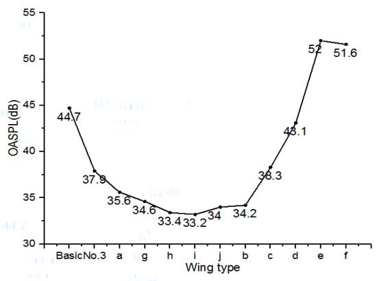
Figure 4.
Overall sound pressure levels of different bionic wings.
In order to further explore the mechanism of noise reduction by the bionic leading-edge microstructure, the wings with different noise effects were selected for comparative analysis. That is to say, the basic wing, wing a, wing i, wing c and wing e were selected as the research objects, and the 1/3 octave sound pressure level analysis was carried out. The results are shown in Figure 5. At the same time, three bionic wings (wing c, wing e, wing i) and basic wings were selected to analyze the pressure fluctuation on the upper surface of the bionic wing. The pressure nephogram is shown in Figure 6.
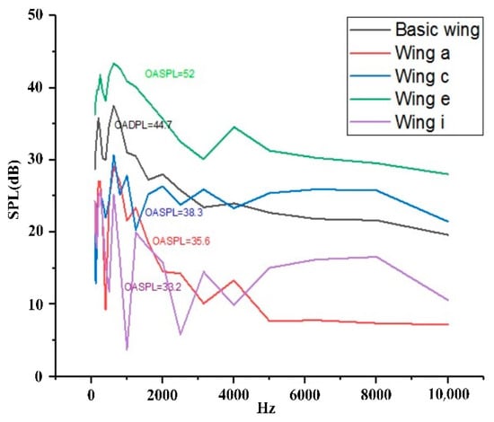
Figure 5.
1/3 octave sound pressure level versus different frequency.
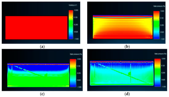
Figure 6.
Pressure nephograms of several bionic wings’ surface: (a) wing e, (b) basic wing, (c) wing c, and (d) wing i.
As seen in Figure 5, compared to the basic airfoil, the sound pressure level of the bionic wing a and wing i was always lower than that of the basic airfoil in the full frequency range, which shows an obvious noise-reduction effect. These bionic wings had different acoustic characteristics in the different frequency range, which was the reason that the 1/3 octave sound pressure level curves of different bionic wings in Figure 5 have intersects. By comparing the SPL curves of the basic wing and bionic wing c, it was found that the sound pressure level of the bionic wing c was lower than that of the basic wing in the mid-frequency range (200 Hz to 6 kHz). It could be found that sound pressure level value was closely related to the acoustics frequency range and the bionic serrated microstructure on the leading edge in this paper had a certain noise-reduction effect in the mid-frequency range.
As can be seen from Figure 6, the leading edge and the upper surface of the bionic wing e had strong pressure fluctuations; that is, the leading-edge noise and the self-noise were very large, so the overall sound pressure level of the bionic wing was the largest. Comparing the pressure nephograms of the upper surface of the basic wing, the bionic wing c and the bionic wing i, it was found that the pressure fluctuation of the leading edge and the upper surface of the wing decreases gradually, which results in the decrease of the overall sound pressure level of the wing noise. Therefore, the reason for noise reduction can be explained as the bionic leading-edge microstructure could significantly change the state and size of the vortices and their distribution on the wing surface, thereby affecting the pressure fluctuations on the leading edge, trailing edge and upper surface of wings, thus affecting the noise level of the wing, and realizing the noise-reduction function of the bionic leading-edge microstructure.
3.3. Effect of Serrated Microstructure Width on Noise Reduction
The size parameters of the leading-edge microstructure of the bionic wing 3 were selected as the reference. By changing the width of leading-edge microstructure serration on the bionic wing and calculating the overall sound pressure level generated by the bionic wing, the influence of the width of microstructure serration on the noise-reduction effect was obtained. The width of the bionic serration microstructure was enlarged by 2, 4, 6, 8, 10, 50, 100 and 200 times, respectively, and numbered r, j, k, L, m, n, o and p in turn. The overall sound pressure level of the bionic wing is shown in Figure 6, and the overall sound-pressure-level reduction is shown in Table 7.
Table 7.
Overall sound-pressure-level reduction of different bionic wings.
From Figure 7, it can be concluded that, under the given conditions in this paper, the change of the width of the leading edge serration had no obvious effect on the noise-reduction effect and level of the bionic wing. In order to further analyze this situation, the basic wing, wing k, wing m and wing o were selected for 1/3 octave sound pressure level analysis, and the sound pressure level curve was drawn, as shown in Figure 8. The pressure fluctuations on the upper surfaces of these bionic wings were analyzed by XFlow software; these pressure nephograms are shown in Figure 9.
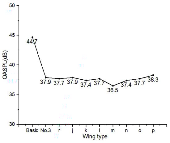
Figure 7.
Overall sound pressure levels of different bionic wings.
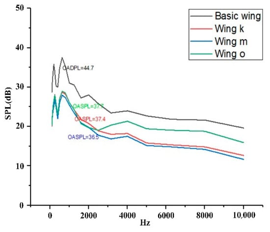
Figure 8.
1/3 octave sound pressure level curves of different bionic wings.
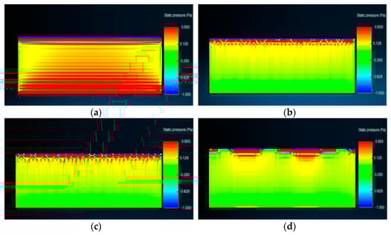
Figure 9.
Pressure nephograms of different bionic wing surfaces: (a) basic wing, (b) wing k, (c) wing m and (d) wing o.
Figure 8 shows that the sound pressure level of the bionic wing with the noise-reduction effect was lower than the basic airfoil in the whole frequency range; that is to say, noise reduction was achieved in the whole frequency range. By comparing wing k and wing o, it could be found that the reduction of the sound pressure level in the leading edge region had a decisive effect on the overall sound-pressure-level reduction of noise.
The pressure nephograms of four bionic wings in Figure 9 show that the pressure fluctuation on the upper surface of the three bionic wings was significantly lower than the basic wings, so the overall sound pressure level of the noise generated by the bionic wings was low. The width of the bionic serration microstructure significantly changed the pressure fluctuation distribution at the leading edge and extended the strong pressure fluctuation to the upper surface of the wing, but it had no significant effect on the overall sound pressure level of the bionic wing, that is, the change of the width of the serration microstructure at the leading edge of the bionic wing had no significant effect on the noise.
4. Experiment
In this paper, the bionic wing 5, with a good noise-reduction effect, was fabricated by an extreme ultraviolet curing process and tested in a wind tunnel. Considering the accuracy of the processing equipment, the size of the bionic microstructure was adjusted. The main characteristic parameters are shown in Table 8. However, due to the large noise in conventional wind tunnels, the noise generated by the interaction between the bionic wing and incoming flow will be concealed. Therefore, the rotational motion of the bionic serration microstructure was used to simulate the wind speed generated in the wind tunnel, and the noise of the serration microstructure in the process of rotation was detected to approximately replace the wind tunnel test. The test system shown in Figure 10 included a self-built low-noise rotary platform, a bionic fan with a microstructure blade, a multifunctional sound level meter system and a computer. In order to reduce noise and resistance as much as possible, the microstructure carrier was designed in the form of a blade, which was fabricated by 3D printing technology. Moreover, the windward surface was rectangular and easy to fix the microstructure. The microstructure was fixed on the windward side of the blade by glue, which was called the bionic blade. The noise measurement range of the multifunction sound level meter was 20–132 dB, A/D digits were 24 bits, the sampling frequency was 48 Hz, and the frequency range was 100–2000 Hz. The rotating speed range of the low noise rotating platform was 0–5000 RPM, and the overall sound pressure level range of noise was 30.5–41.2 dB. The sound level meter receiver fixed at 10 cm above the center of the fan blade receives pressure fluctuation caused by air when the fan rotated.
Table 8.
Parameters of the leading-edge model.
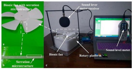
Figure 10.
Noise measurement device of the rotating platform: (a) bionic fan, (b) serration microstructure chip and (c) rotating platform.
In this paper, the noise of the basic blade and the bionic blade are measured, respectively. The rotating speed of the rotating platform was set to 1700 RPM, 2300 RPM and 3000 RPM; hence, the relative velocity range between the airflow and the bionic leading-edge microstructure was 4.5–21.9 m/s, which simulated the flying speed of dragonflies [15]. The overall sound pressure levels of the two blades measured by the multifunction sound level meter at three rotational speeds are shown in Figure 11. By observing the histogram, it can be concluded that: with the increase of the rotating speed of the rotating platform, the overall sound pressure level of noise generated by two groups of blades increases accordingly. However, the overall sound pressure level of the bionic blade was lower than the basic fan blade at three rotational speeds. The overall sound-pressure-level reduction of the bionic blade at 1700 RPM, 2300 RPM and 3000 RPM was 1.4 dB, 2.8 dB and 2.1 dB, respectively. Therefore, it could be considered that the leading-edge microstructure of the leading edge of dragonfly wings can reduce noise. However, the level of noise reduction was quite different from the simulation resulted. The reasons can be considered from three aspects: (1) under the simulation conditions, there was no interference from external noise; (2) under the simulation conditions, the inflow of wind was an ideal model of positive-to-microstructure. Under the experimental conditions, the flow pattern was uncertain, and the test mode of rotational motion was quite different from that of linear inflow. (3) The manufacturing and installation accuracy of serration microstructure needs to be improved.
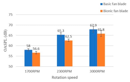
Figure 11.
Overall sound pressure level of the basic fan blade and bionic fan blade at different rotational speeds.
5. Conclusions
During the development of flapping-wing aircraft, our team found that the surface microstructure of dragonfly wings is related to their low-noise flight capability. In this paper, the geometric characteristics of dragonfly wings’ leading edge are extracted, optimized and modeled. Then, according to the practical application requirements and the principle of scale law, the bionic leading-edge microstructural model is enlarged. After simulation analysis and experimental verification, the following conclusions are obtained:
(1) The noise-reduction effect of the leading-edge microstructure of the wing is remarkable with the increase of the overall size. When amplified 4 times, it has the best noise-reduction effect, with an overall sound-pressure-level reduction of 12.5 dB. After this, the noise-reduction effect decreases rapidly and even increases the noise level.
(2) The height of the serration microstructure affects the noise-reduction effect and level of the bionic wing. The noise-reduction effect is remarkable with the increase of serrated height. When the height is amplified 1.8 times, the noise-reduction effect is the best. At this time, the serration height of the microstructure is 230.58 μm, with an overall sound-pressure-level reduction of 11.5 decibels; when we continue to increase the altitude, the effect of noise reduction rapidly attenuates.
(3) The change of serration microstructural width can obviously change the pressure fluctuation distribution at the leading edge and extend the strong pressure fluctuation to the upper surface of the wing, but it has no significant effect on the overall sound pressure level of serration microstructural, that is, the width of serration microstructure has no significant effect on noise reduction.
(4) Observing the 1/3 octave sound pressure level curve of the bionic wing, it can be concluded that the sound pressure level in the leading edge region has a decisive influence on the overall sound pressure level of noise, and the bionic serration microstructure has an obvious noise-reduction effect in the leading-edge region.
In conclusion, the microstructure of dragonfly wings’ leading edge has an effect of reducing aerodynamic noise. Moreover, the microstructure can significantly change the eddy current state, the vortex size and its distribution on the wing surface, and then affect the pressure fluctuation on the leading edge, trailing edge and the upper surface of wings, thus affecting the overall sound pressure level of the noise generated by the wing, thereby reducing the noise of the bionic wing. In the follow-up work, the degree of simulation and manufacturing accuracy of microstructure will be improved, and the noise-reduction effect of dragonfly wing leading-edge microstructure will be further studied to promote practical application.
Author Contributions
Conceptualization S.J. and Y.H.; conducting a research and investigation process Y.H.; draft preparing Q.L. (Qiang Li); design of methodology and revision support H.W.; software development Y.L.; management and coordination responsibility for the research activity planning and execution X.Z.; providing the experiment ideas and funding acquisition Q.L. (Qiang Liu). All authors have read and agreed to the published version of the manuscript.
Funding
This research was funded by National Nature Science Foundation of China (NSFC), grant number U1601203, U19A20104; Jilin Province Science and Technology Development Program, grant number 20180101321JC, 20190302099GX; Jilin Province ndustrial Technology of Research and Development, grant number 2019C037-3; and Science and Technology project of Jilin Provincial Department of Education, grant number JJKH20200955KJ.
Institutional Review Board Statement
Not applicable.
Informed Consent Statement
Not applicable.
Data Availability Statement
More details about the data could be obtained by contacting the corresponding author via the email.
Conflicts of Interest
The authors declare that they have no known competing financial interests or personal relationships that could have appeared to influence the work reported in this paper.
References
- Rajabi, H.; Moghadami, M.; Darvizeh, A. Investigation of microstructure, natural frequencies and vibration modes of dragonfly wing. J. Bionic Eng. 2011, 8, 165–173. [Google Scholar] [CrossRef]
- Lau, A.S.H.; Haeri, S.; Kim, J.W. The effect of wavy leading edges on aerofoil–gust interaction noise. J. Sound Vib. 2013, 332, 6234–6253. [Google Scholar] [CrossRef]
- Selig, M.S.; McGranahan, B.D. Wind Tunnel Aerodynamic Tests of Six Airfoils for Use on Small Wind Turbines. J. Sol. Energy Eng. 2004, 126, 986–1001. [Google Scholar] [CrossRef]
- Lilley, G. A study of the silent flight of the owl. In Proceedings of the 4th AIAA/CEAS Aeroacoustics Conference, Toulouse, France, 2–4 June 1998. [Google Scholar]
- Gill, J.R.; Zhang, X.; Joseph, P. Effects of Real Airfoil Geometry on Leading Edge Gust Interaction Noise. In Proceedings of the 19th AIAA/CEAS Aeroacoustics Conference, Berlin, Germany, 27–29 May 2013. [Google Scholar]
- Biedermann, T.M.; Chong, T.P.; Kameier, F.; Paschereit, C.O. Statistical–Empirical Modeling of Airfoil Noise Subjected to Leading-Edge Serrations. AIAA J. 2017, 55, 3128–3142. [Google Scholar] [CrossRef]
- Narayanan, S.; Chaitanya, P.; Haeri, S.; Joseph, P.; Kim, J.W.; Polacsek, C. Airfoil noise reductions through leading edge serrations. Phys. Fluids 2015, 27, 025109. [Google Scholar] [CrossRef]
- Migliore, P.; Oerlemans, S. Wind tunnel aeroacoustic tests of six airfoils for use on small wind turbines. J. Sol. Energy Eng.-Trans. Asme 2004, 126, 974–985. [Google Scholar] [CrossRef]
- Greenewalt, C.H. The Flight of Birds: The Significant Dimensions, Their Departure from the Requirements for Dimensional Similarity, and the Effect on Flight Aerodynamics of That Departure. Trans. Am. Philos. Soc. 1975, 65, 1–67. [Google Scholar] [CrossRef]
- Rayner, J.M.V. A new approach to animal flight mechanics. J. Exp. Biol. 1979, 80, 17–54. [Google Scholar]
- Norberg, U.M. (Ed.) Vertebrate Flight: Mechanics, Physiology, Morphology, Ecology and Evolution; Springer: Berlin, Germany, 1989; DM 238; 291p. [Google Scholar]
- Tennekes, H. The Simple Science of Flight; The MIT Press: Boston, MA, USA, 1997. [Google Scholar]
- Shyy, W.; Kang, C.K.; Chirarattananon, P.; Ravi, S.; Liu, H. Aerodynamics, sensing and control of insect-scale flapping-wing flight. Proc. Math. Phys. Eng. Sci. 2016, 472, 20150712. [Google Scholar] [CrossRef] [PubMed]
- Mao, S. Unsteady Lift Mechanisms in Insect Flight. Adv. Mech. 2002, 32, 425–434. [Google Scholar]
- Wakeling, J.; Ellington, C. Dragonfly flight. II. Velocities, accelerations and kinematics of flapping flight. J. Exp. Biol. 1997, 200, 557–582. [Google Scholar] [PubMed]
Publisher’s Note: MDPI stays neutral with regard to jurisdictional claims in published maps and institutional affiliations. |
© 2021 by the authors. Licensee MDPI, Basel, Switzerland. This article is an open access article distributed under the terms and conditions of the Creative Commons Attribution (CC BY) license (http://creativecommons.org/licenses/by/4.0/).