Article

Dynamic Balance of the Head in a Flexible Legged Robot for Efficient Biped Locomotion

by
Domenico Lisitano
1,
Elvio Bonisoli
1,
Carmine Tommaso Recchiuto
2 and
Giovanni Gerardo Muscolo
3,*
1
Department of Mechanical and Aerospace Engineering (DIMEAS), Politecnico di Torino, Corso Duca degli Abruzzi, 24, 10129 Torino, Italy
2
Department of Informatics, Bioengineering, Robotics, System Engineering, University of Genova, Via all’Opera Pia, 13, 16145 Genova, Italy
3
Department of Computer Science, University of Verona, Ca’ Vignal 2-Strada Le Grazie, 15, 37134 Verona, Italy
*
Author to whom correspondence should be addressed.
Appl. Sci. 2021, 11(7), 2945; https://doi.org/10.3390/app11072945
Submission received: 8 February 2021 / Revised: 17 March 2021 / Accepted: 22 March 2021 / Published: 25 March 2021

Abstract

:
In the biped robotics domain, head oscillations may be extremely harmful, especially if the robot is teleoperated, since vibrations strongly reduce the operator’s spatial awareness. In particular, undesired head oscillations occur in under-actuated robots, where springs and passive mechanisms are used to achieve a human-like motion. This paper proposes an approach to reduce the vibrations of a biped robot’s head; the proposed solution does not affect the dynamic locomotion properties, on which specific control logic could have been already tuned. The approach is tested on Rollo, a flexible-biped-wheeled robot, whose head vibrates throughout the robot locomotion. The two requirements, i.e., head vibration reduction and unchanged Rollo locomotion properties, are traduced in constraints to the robot possible modifications. Based on a 1D finite element model of the robot, tuned on experimental modal analysis, the undesired vibration causes are detected, and a solution for their reduction is proposed. Rollo’s head vibration amplitude is attenuated using a tuned vibration absorber, which achieves impressive performance in the robot. An archetype of the proposed vibration absorber is tailored designed on Rollo, without invasive changes to the robot structure. The proposed approach solves a significant problem in the biped robotic research community. The approach used to reduce the Rollo head oscillations may be utilized in other biped robot machines with or without flexible legs.

1. Introduction

Robotics is a multidisciplinary research field, increasingly present in nowadays daily life. Robotics is modifying the classical design concepts, joining mechanics, electronics, and computer science knowledge, including life science considerations, resulting in the design of novel systems, which actively interact with the environment [1,2,3]. The design of such systems is innovative and includes many more aspects than classical systems design, e.g., variable stiffness actuators, soft robotics, dielectric elastomer actuators, artificial skins. The significant amount of possible interactions between different engineering fields increases the creativity and opens-up novel frontiers in design.
Humanoid robotics is a novel research branch [4], oriented to conceive systems with human-like behaviour. However, the design of a machine, emulating the complexity of the human body and mind, is a big step to pursue; therefore, many systems are conceived to reduce the gaps between human and humanoid robots [5,6,7].
Among several human characteristics useful for humanoid robots, many research efforts were dedicated to replicate the locomotion mechanisms of humans and legged animals [8,9], which are considered the reference systems of the bio-inspired robotic research [10]. The best compromise between locomotion performance and input power to the actuators is desired to reproduce bio-inspired locomotion in robots. Energy harvesting approaches were proposed in [11,12] to optimize the input power to actuators during the cyclic legged locomotion using passive elements. Calibrated actuations in biped and quadrupedal robots were adopted to improve the locomotion performance [2,13]; algorithms for locomotion control were implemented on legged robots, such as the central pattern generator [14,15] and the simplified Zero Moment Point (ZMP) approach [16] to perform biped locomotion in a planar surface [17]. In recent works [18,19], the dynamic balance of biped robots is studied with the final aim to bypass the ZMP approach. However, the dynamic balance is an important problem in biped locomotion, and in order to solve the problem, some novel solutions have been conceived, e.g., wheels on feet [20,21].
Recently, some of the present authors have proposed a novel biped wheeled robot with a flexible structure, named Rollo [22]. Rollo is a simple robot, merging the characteristics of biped wheeled robots with flexible legs to increase the performance and minimize the number of actuators. The robot flexibility helps the locomotion performance; however, an undesired oscillation of the robot head during the locomotion is generated, as shown in [23]. The head vibrations could reduce the dynamic balance of the robot, and a proper attenuation of the head oscillations is necessary to increase the safety of the human–robot interactions.
Indeed, vibration damping [24] is a common problem for several engineering fields, e.g., civil [25,26], automotive [27,28], aerospace [29], and tooling machines [28]. Vibrations are usually reduced through active devices and control strategy [30,31,32] or passive damping [33,34]. In robotics, the vibration damping is studied for increasing the bipedal or quadrupedal performance of robots, as shown in [2,13,35,36].
This paper aims at reducing the head vibration level without modifying the properties of the robot. The robot head’s oscillations are analyzed in detail, evaluating some causes of vibrations, e.g., the robot flexible structure and the friction with the ground. A solution to reduce vibrations is proposed and implemented in the robot model.
In the proposed approach, the best compromise between performance and constraints is a passive solution, i.e., a tuned mass–spring–damper system (TMD). The tuned vibration absorber is probably the oldest and most commonly used passive device to attenuate vibrations. The first patent on this kind of device belongs to Frahm [37]; the device was later optimized for a single degree of freedom (sdof) system by Den Hartog [38]. The approach is here tested on the Rollo robot, and validated with dynamic simulations. A TMD device is designed and implemented on Rollo to asses the reduction of the head oscillations.
The prototype of the Rollo robot and its model are described in Section 2, The model validation against experimental results is presented in Section 3. The robot head vibrations are numerically investigated in Section 4 and a possible solution to attenuate the undesired oscillations is proposed.

2. Rollo Robot and FE Model

2.1. Rollo in Details

Rollo, shown in Figure 1, was conceived as an avatar robot for people affected by Amyotrophic Lateral Sclerosis (ALS) disease, able of being a controller using advanced brain–computer interfaces. ALS is a chronic neurodegenerative disease that reduces human motion and interaction capabilities. A biped robot may be used to assist people affected by ASL [22,39], and Rollo robot has been specifically designed for those patients, given its simple architecture, lower power supply, and high vertical stability.
Rollo is a biped, flexible-leg wheeled-feet robot. The two legs are connected with a beam-like structure at the top, horizontal and parallel to the ground. Each leg is connected to the feet on the lower side. The robot head is located on the beam linking the two legs. Each leg is made of one or more flexible modules. The robot feet are constituted by two active driving wheels, two passive wheels to guarantee vertical stability, and one heavy motor, chosen to increase stability and lower the center of mass of the robot. The weight of the robot naked structure is almost 23.5 kg, and it is 30 kg considering also non-structural elements and accessories; the overall dimensions in the configuration with two flexible modules for each leg are about 80 × 40 × 30 cm.
Two locomotion types are embedded in Rollo: human-like walking alternating the motion of the feet, the focus of the paper, and simpler locomotion with the feet always parallel, refer to [22] for more details. In the human-like locomotion type, the flexible modules of each leg absorb energy and give it back, net of dissipations, in the next step, i.e., as it happens in human walking. The human-like walking mechanism minimizes the amount of external energy required for walking.
Rollo is driven by an input, which may be externally given to the robot by a joystick, a mobile, brain–computer interface, or other communication systems. The input parameters required to control the robot are the speed, locomotion type, and the direction (forward, backward, turn left, turn right) [22]. Tests on Rollo locomotion were performed in [22], in the configurations with two (Figure 1 right) and three (Figure 1 left) flexible modules for each leg. The tests highlight better locomotion performance in the configuration with two flexible modules for each leg and better capability to turn left or right for the robot with three flexible modules in each leg; however, undesired oscillations of the robot head were detected in each configuration [22]. The oscillations were neglected in previous works focused on the design of the robot and locomotion control logic [22]. Head oscillations should be avoided because they can compromise the interaction with people for which it is conceived. In particular, Rollo is an avatar robot, and the head of the robot (constituted by an iPad) has the webcam onboard, reproducing in real-time the external environment on the PC of the patient. Furthermore, the iPad of the robot reproduces in real-time the video of the patient for the interaction with people. Oscillations of the Rollo head are undesired because they compromise Rollo communication capabilities.
Rollo design requires modifications to attenuate the undesired head oscillations. The design changes must not change the robot nature, i.e., mass balance and human-like locomotion logic. Therefore, the necessary changes have to comply with some constraints: the robot mass cannot increase more than 1% of the total mass, the center of gravity vertical height cannot increase more than 3 cm, otherwise the robot vertical stability is compromised. Moreover, Rollo’s overall dimensions and electrical range should not change.

2.2. Rollo Lupos FE Model

The structural model of the Rollo robot is developed using Lupos [40], a custom finite element (FE) software developed at the Politecnico di Torino. Lupos is a parametric FEM software able to handle the most common 1D, 2D, and 3D elements used in FE simulations.
The structural model of Rollo, shown in Figure 2, is implemented using: 1D Timoshenko beam elements, rigid joint elements, and a specific library of Lupos dedicated to helical springs. The Timoshenko beam elements have rectangular or circular cross-section and include bending, axial, and torsional behaviours; the rigid joints elements create roto-translation kinematic relationships between master–slave nodes.
Electric motors and gearboxes are very stiff elements, compared to the other components’ flexibility; therefore, they are modeled as stiff beam elements, with equivalent densities to match the component weights (3.6 kg each motor and 2.3 kg each gearbox). Wheels are modeled as flexible bodies, with density and Young modulus of the rubber. Cylindrical beam elements are used to model the driving wheels steel shaft, while flexible steel beams represent the angular connections between the gearboxes and the stability wheels. The beam linking the left and right side of the robot is discretized using aluminum Timoshenko beam elements. Particular attention is given to the correct tuning of the elastic modules, see Appendix A, since they are the responsible components of Rollo locomotion and vibration transmission from the driving wheels to the head.

3. Design and Validation of the Rollo Model

Rollo head vibrations are a consequence of the mechanical system structural dynamics properties; therefore, the system modal properties, i.e., natural frequencies, damping ratios, and mode-shapes, should be investigated to detect the undesired frequencies inducing the head vibration and propose modifications solving the problem. A tuned model is required to simulate the head vibration problem experienced during experimental investigation in [22] and test the proposed solution with a modification prediction strategy on the numerical model. Dynamics properties of the model and Rollo prototype are presented in the following and their correlation is assessed to validate the model.

3.1. Numerical Modal Analysis of the Rollo Robot

Modal analysis [41] is a well-established mathematical technique to find out the modal properties of a mechanical system. Numerical modal analysis (FEA) is performed on the undamped Rollo model [41,42]. Global mass M g and stiffness K g matrices are obtained from the Lupos model, which uses classical FEM matrix assembly technique [43] to generate the global matrices. The total number of degrees-of-freedom (dofs) is N = 3432, thus M g , K g , R N , N . Numerical modal analysis is performed on the reduced system considering only the n active dofs. The reduction from the global number of dofs N to the active dofs n considers the slave dofs depending on other masters (and active) dofs, through kinematic relationships, and dofs on which boundary conditions are applied. The reduced model posses a total of n = 2382 active/independent dofs. The mass M R n , n and stiffness K R n , n describing the dynamic of the independent dofs are obtained from the global matrices as:
M = T T M g T K = T T K g T
where T R N , n is a transformation matrix taking into account kinematic master/slave relationships and boundary conditions. The discrepancies between the total number of dofs N and the independent number of dofs n is mainly due to the rigid connections used to lock the deformation of two spires for each extremity of each spring, as discussed in Appendix A. The eigenproblem in Equation (2) is solved for the R = 20 lowest numerical natural frequencies ω r and mode shapes ϕ r R n , 1 :
( K ω r 2 M ) ϕ r = 0 r = 1 , . . . , 20
The problem is solved in almost free–free conditions, although soft lumped springs are linked to the middle of the top beam to replicate the experimental setup, see Section 3.2. Mode shapes ϕ r computed on the n active dofs are expanded to the total number of dofs N:
φ r = T ϕ r
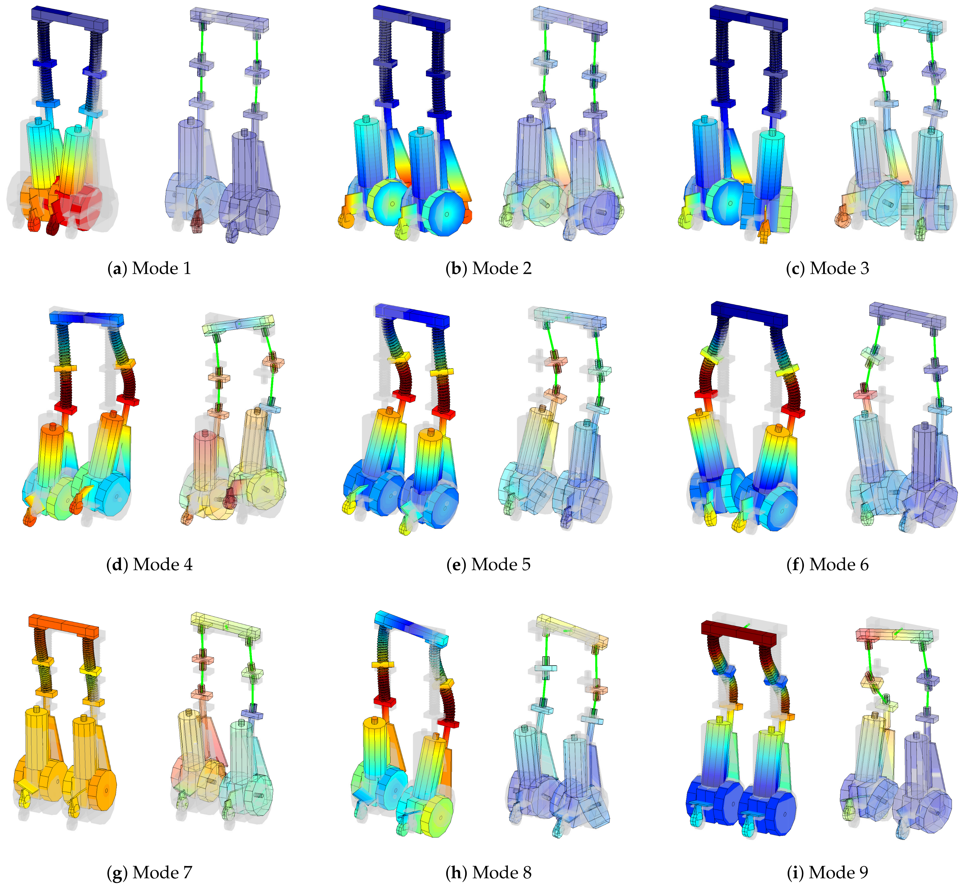
where φ r R N , 1 is the rth mode shape expanded to the system global dimension N. The numerical natural frequencies f n = 1 2 π ω n of flexible modes are listed in Table 1 and the numerical mode shapes φ r , obtained through Equations (2) and (3), are shown in Figure 3 (on the left side of each sub-figure).
The mode shapes φ r represent the vibration shape in terms of displacement, velocity, and accelerations at each natural frequency of the system. They are defined unless of a multiplicative constant; therefore, the absolute value is not essential, but only the overall shape makes sense. In the figure, the colours represent the amount of deviation of the mode shape with respect to the undeformed configuration: cold colours, i.e., toward blue, represent a portion that is not moving, while hot colours represent portions of the system which are increasingly vibrating from blue to red.

3.2. Experimental Modal Analysis of Rollo Robot

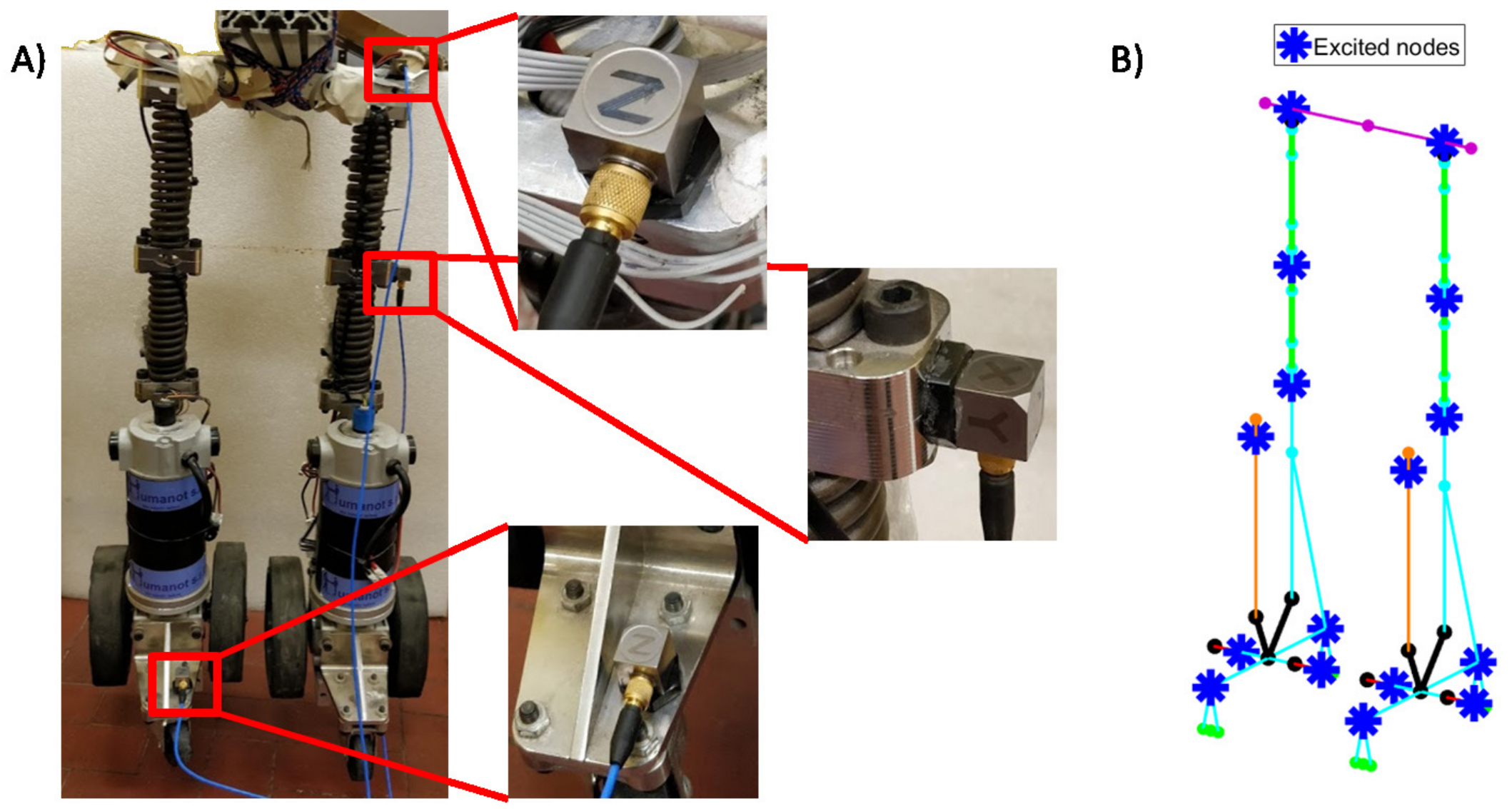
Experimental modal analysis (EMA) on the Rollo prototype is necessary to validate the numerical model. EMA is performed in free–free conditions on the structural system depurated of all the accessories. The robot is hanged up through soft elastic bands in the middle of the up-beam, as shown in Figure 4A. Roving hammer test is performed on the robot. The system was excited using a PCB 086C03 instrumented hammer, PCB 356A15 tri-axial accelerometers were used to measure the acceleration responses of the system. The accelerometers are located in three points, shown in Figure 4A: right leg in the proximity of the front stability wheel, left leg in the steel attachment between the two spring, and on the up-beam in correspondence of the left leg beam attachment. The robot is excited in 16 points, shown in Figure 4B, in the three Cartesian directions, where physically possible. In total, 46 dofs are excited.
The excitation force and the measured responses are acquired using an LMS SCADAS Mobile acquisition system. The acquired signals are processed using Siemens Test.Lab software. Signals are measured for 4 s, with a sampling frequency of 4096 Hz. Inertance frequency response functions (FRFs) are computed using H 1 estimator, averaged on five impact repetitions. The exponential force window is applied to the force and exponential windows on the response. In total, 138 FRFs are acquired. Modal properties, i.e., natural frequencies listed in Table 1 and mode shapes shown in Figure 3 (right side of each sub-figure), are identified using PolyMax algorithm [44] and optimized using MLMM [45]. Some of the identified mode shapes show a consistent degree of complexity. Complex mode shapes are an index of non-classical damping acting on the structure due to localized dissipations. The experimental mode-shapes show a non symmetric behaviour; in particular, the left leg is more flexible than the right one.

3.3. Model Validation

The modal properties computed using the numerical model described in Section 2.2 and the EMA identified modal properties (Figure 3 and Table 1) are compared to assess the model goodness. Modal properties are compared using the modal assurance criterion for complex modes shapes (MACX) [46]. MACX index is used to perform pairing between two sets of modal vectors. The MACX is a real value between 0 and 1; it is MACX = 1 when two mode shapes are exactly the same and 0 when two mode shapes are totally different. MACX is defined as follows:
MACX ϕ j , ϕ k = | ϕ j H ϕ k | + | ϕ j T ϕ k | 2 ϕ j H ϕ j + | ϕ j T ϕ j | ϕ k H ϕ k + | ϕ k T ϕ k |
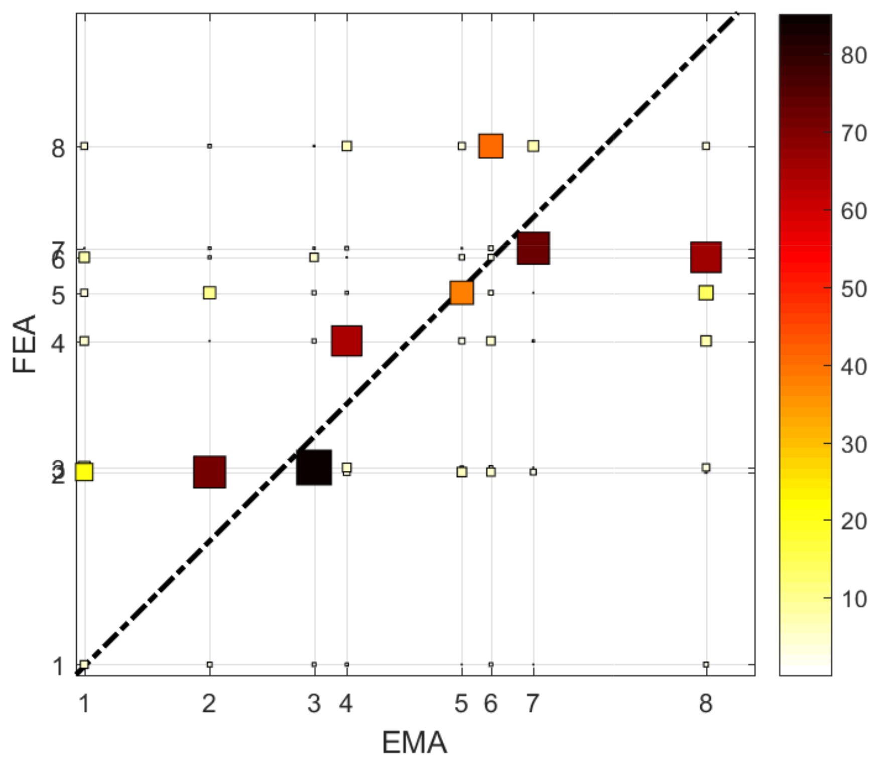
where ϕ j and ϕ k are the two complex modal vectors to be compared, T is the transpose operator, and H is the Hermitian operator (complex conjugate transpose). A matrix of MACX values is obtained comparing the experimental and numerical sets of mode shapes. In the ideal case that the two sets are the same, a matrix with 100% in the matrix diagonal is expected. The MACX matrix obtained comparing the numerical and experimental mode-shapes of Figure 3 is shown in Figure 5, where the spacing between the modes is proportional to the modes natural frequencies. If the mode paring is close to the iso-frequency line (black dashed-dot line), the mode shapes are similar, and the natural frequencies are close.
The MACX matrix in Figure 5 shows a good correlation between numerical and experimental modes: the MACX value is generally high and close to the iso-frequency line. A good correlation between experimental and numerical modes is achieved for both mode shapes and natural frequencies, highlighted from both the MACX matrix in Figure 5 and the mode shapes graphical comparison in Figure 3. An exception is the first mode, which is at a low natural frequency of about 0.5 Hz and the experimentally identified mode shape is not reliable. Furthermore, numerical and experimental mode shapes 6 and 8 are switched; however, their natural frequencies are pretty close; hence the result is reasonable. The good correlation between numerical and experimental modal properties validates the structural model developed in Lupos.

4. Head Vibration Reduction of the Rollo Model: Results and Discussion

The robot structural dynamics model, tuned on the experimental results in the previous section, is used to perform a simulation of Rollo human-like locomotion and quantify the head’s vibration level. The boundary conditions of the tuned model are updated to reflect the locomotion condition: the elastic lumped elements representing the elastics bands used during the experiments are removed, and additional boundary conditions are introduced to represent the wheel-floor contacts. In particular, the vertical displacements of the wheels are constrained, and viscous dampers are introduced at the wheel translations to model the dissipation at the wheel-floor contacts. The viscous damping coefficients are tuned on the experimental evidence in [22]. The time-domain simulation of Rollo human-like locomotion is performed to evaluate the head oscillations. A similar simulation was successfully performed in [18] using a multibody model of Rollo, in which the two elastic modules in each leg were modeled as lumped spring elements. The simulations were efficient to evaluate the locomotion performance, but the model was too rough to predict the head vibrations. The same locomotion simulation is performed with the present tuned model in the Lupos environment. The driving torques provided by the motors were simplified and substituted by the equivalent alternating horizontal force applied at the wheels center.

4.1. Numerical Simulation

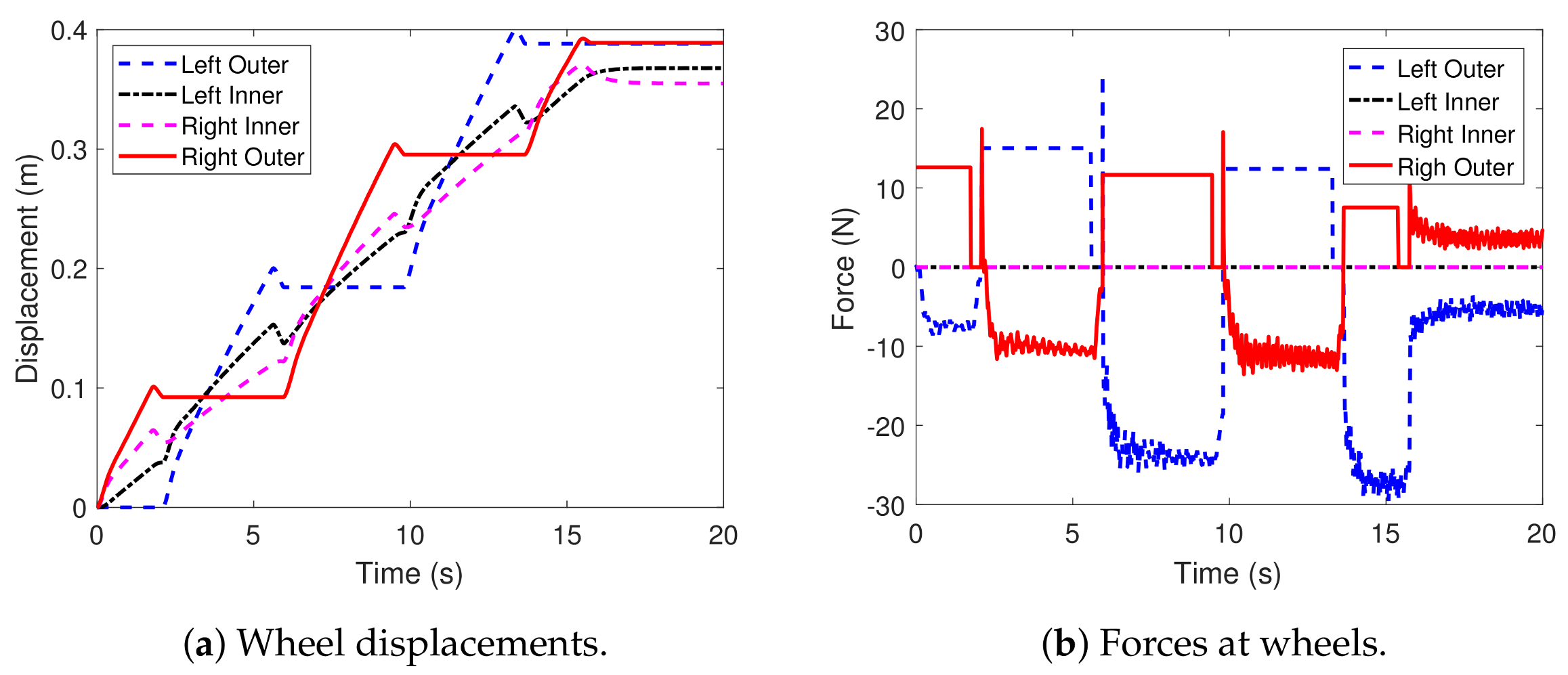
A simulation of Rollo forward motion on a straight trajectory is performed using the procedure described in Appendix B. The Rollo mission is to advance 40 cm and stop in front of the target point in 20 s. The simulation is performed in the modal domain using the R = 20 lowest frequency modes. Rollo model completes the mission with 3 steps for the right leg and 2 step for the left leg, shown in Figure 6.
The forces applied on the left and right foot, shown in Figure 7b are calibrated to obtain the wheel displacements, shown in Figure 7a, consistent with the human-like locomotion experimental tests [23].
The simulation is representative of the human-like locomotion type of Rollo, and it is adequate to assess the vibration level at Rollo head. The vibrations of the robot head are evaluated at the center of the supporting beam on which the head is fixed. The head vibrations are evaluated in term of longitudinal (along z) accelerations, which are shown in Figure 8a. The spectrogram of the acceleration evolution during the motion, shown in Figure 8b, highlights the harmonic mainly responsible for the undesired head vibration at about 4 Hz. The detected frequency corresponds to the third mode shapes of Rollo system, constrained with proper boundary condition representing the locomotion working condition, shown in Figure 8c. The undesired oscillations are produced by the detected mode-shape, which involves the bending of the legs’ elastic modules around the x-axis and produces a horizontal vibration of the Rollo head.

4.2. Head Vibration Reduction

The head vibration problem is related to the 3rd mode shapes of the robot on the floor, which has a relatively small damping ratio ζ = 2.2 % . If the damping ratio of this mode shape was increased, the vibration level of the Robot head would be substantially reduced.
The structural modification must be focused on increasing the 3rd mode shape’s damping ratio only; a general increment of the system dissipations would downgrade the locomotion performance, dissipating more energy at each step and reducing the robot range.
Head oscillation could be attenuated using an active control strategy; usually, a velocity feedback control achieves pretty good performances in attenuating selective harmonics [47,48,49]. An active control strategy requires a sensor and an actuator at the head location to measure the dynamics and provide the force to attenuate the head oscillation. The undesired vibration frequency is f u n d = 4.1 Hz; therefore, the active control logic sampling frequency could be around 200 Hz, i.e., not extraordinarily high and suitable for an iPad. Hence, the accelerometer sensor included in the iPad could be used as sensor because the iPad is located at the robot head, precisely where the vibrations should be measured. Therefore, the sensor is already included in the robot, without any structural modification. The control logic could also be implemented in the iPad. The force could be provided by an inertial actuator placed at the Rollo head [50]. The necessity of an actuator is the main disadvantage of the active control strategy; the main reasons are: (1) the size and weight of the inertial actuator able to provide the required force could exceed the mass limit constrain and (2) it should provide a continuous force during the robot locomotion, which means it requires continuous energy to be efficient which is even a more important problem. Optimisation strategies to minimize the actuator required power exist [51]; however, the energy used for the head vibration reduction substantially reduces the robot range. The energy required is an important drawback of active control in the specific application, which propounds for implementing a passive solution.
The requirements for the selective increment of damping ratio and passive damping design suggest the use of an optimized vibration absorber, placed on the supporting beam, to attenuate head vibrations. A dynamic vibration absorber consists of a mass m a connected to the primary system through a spring, having stiffness k a , and a viscous damper, having damping coefficient c a . The dynamic vibration absorber adds a dof to the system, but if the dynamic vibration absorber is tuned on a system natural frequency, it reduces the original system oscillation amplitude. However, an additional natural frequency related to the added dof is generated. The optimal calibration of spring stiffness k a and damper viscous damping coefficients c a let to minimize the response amplitude of the system at an arbitrary undesired frequency f u n d .
In the case of single degree of freedom system (sdof), the optimal values of mass and stiffness are tuned on the undesired natural frequency f u n d and optimized to minimize the amplitude of the two resonances in the inertance transfer function, as follow:
f u n d = 1 2 π k m = 1 2 π k a m a , c a = k m 3 μ 3 2 1 + μ 3 , μ = m a m
where m and k are the mass and stiffness of the sdof system. The extension of the tuned mass damper to multi degrees of freedom (mdof) systems makes the analytical computation of k a and c a dependent on the system properties and the number of dofs. Therefore, in the case of mdof systems, the spring stiffness k a and damper viscous coefficient c a are minimizing the amplitude of the resonances of the transfer function between the input force to the system in operative condition and the point of the system which has undesired oscillations [52].
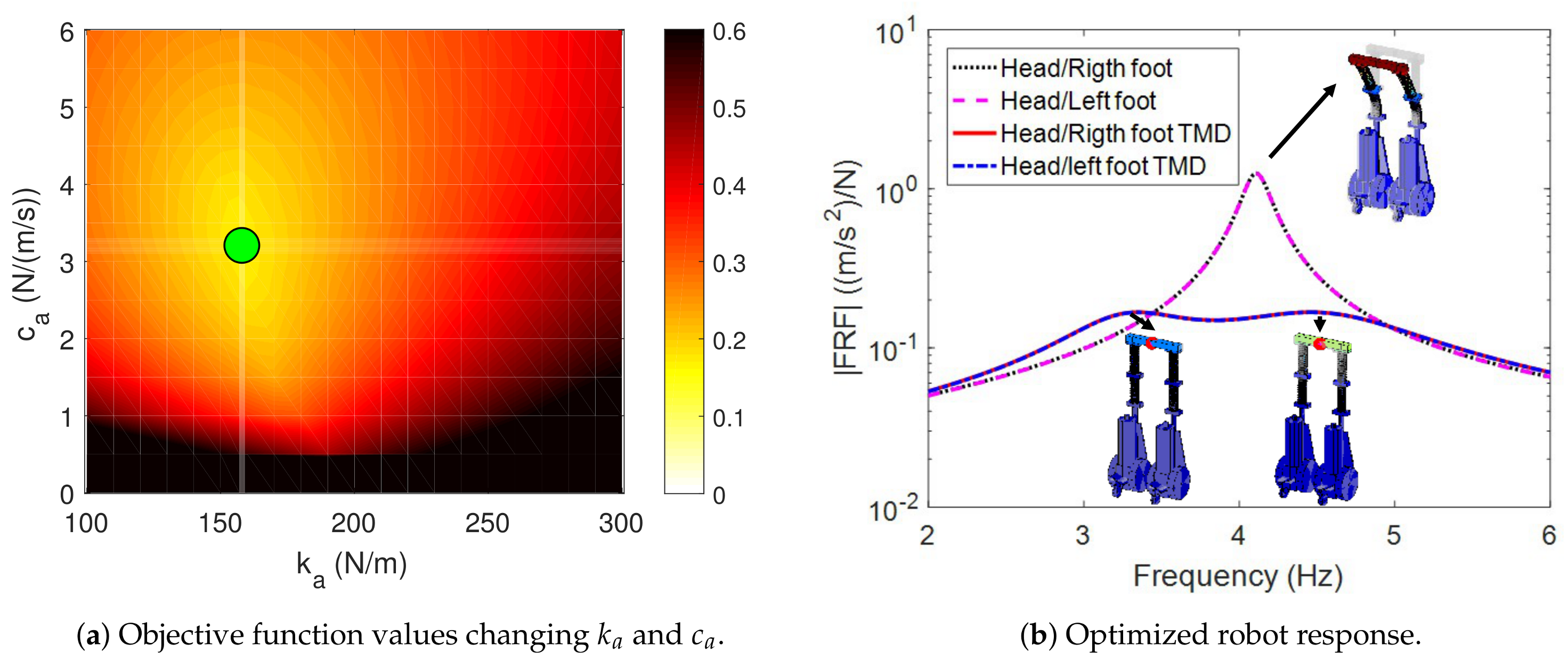
During the robot motion, the input forces are at the wheel–floor contacts, and the reference output is the center of the head supporting beam, where the robot head is located. The system input forces are the traction forces produced by the wheel-floor contacts; Rollo has four driving wheels, two wheels for each foot. The total vibrations at the robot head can be obtained using the superposition principle of the vibration produced by each wheel, and since the traction forces are all the same during straight motion, the sum of the transfer functions between each wheel and the head location had to be optimized. The value of the vibration absorber mass m a is chosen considering the mass constraint given in Section 2, i.e., m a = 0.01 m t o t = 0.3 kg , where m t o t = 30 kg is the total weight of the robot considering structure and accessories. The spring stiffness k a and viscous damping coefficient c a are obtained from the optimisation procedure. The objective function to minimize is the sum of the resonances amplitude in the transfer function between the driving wheels and the head location [43], in the frequency range 2 ÷ 6 Hz, which includes the undesirable resonance frequency f u n d = 4.1 Hz . The objective function trend changing k a and c a is shown in Figure 9a. The optimal stiffness k a and damping c a , which contemporary minimize the response amplitude of both the Rollo head and the dynamics of the vibration absorber added mass m a are k a = 158.2 N / m and c a = 3.2 N / ( m / s ) , i.e., at the green point in Figure 9a. The natural frequencies and damping ration of the two resonance are f 3 = 3.3 Hz , ζ 3 = 12.7 % and f 4 = 4.6 Hz , ζ 4 = 14.6 % . The tuned mass damper increases the damping ratio of the undesired dynamics more than one order of magnitude with respect to the original design. The driving wheel-head transfer function obtained with the proposed solution is compared to the original behaviour of Rollo’s head, in Figure 9b: the tuned mass damper splits the original resonances into two peaks, as expected, the optimal value obtained for k a and c a let to minimize the amplitude of the two peaks. The acceleration amplitude of the head due to excitation at wheel location is reduced by one order of magnitude, which is an excellent improvement.
The forward motion simulation performed in Section 4 is performed again with the implementation of the proposed tuned mass damper. The robot head vibrations are compared to the original design in Figure 10. The amplitude of vibrations of robot head generated at each step are successfully reduced: the acceleration peaks decrease, and the vibrations are attenuated quickly. An objective evaluation of the TMD performance is given by the RMS of the head acceleration: in the robot original design the RMS was 0.55 m / s 2 , while in the improved version it is 0.34 m / s 2 .
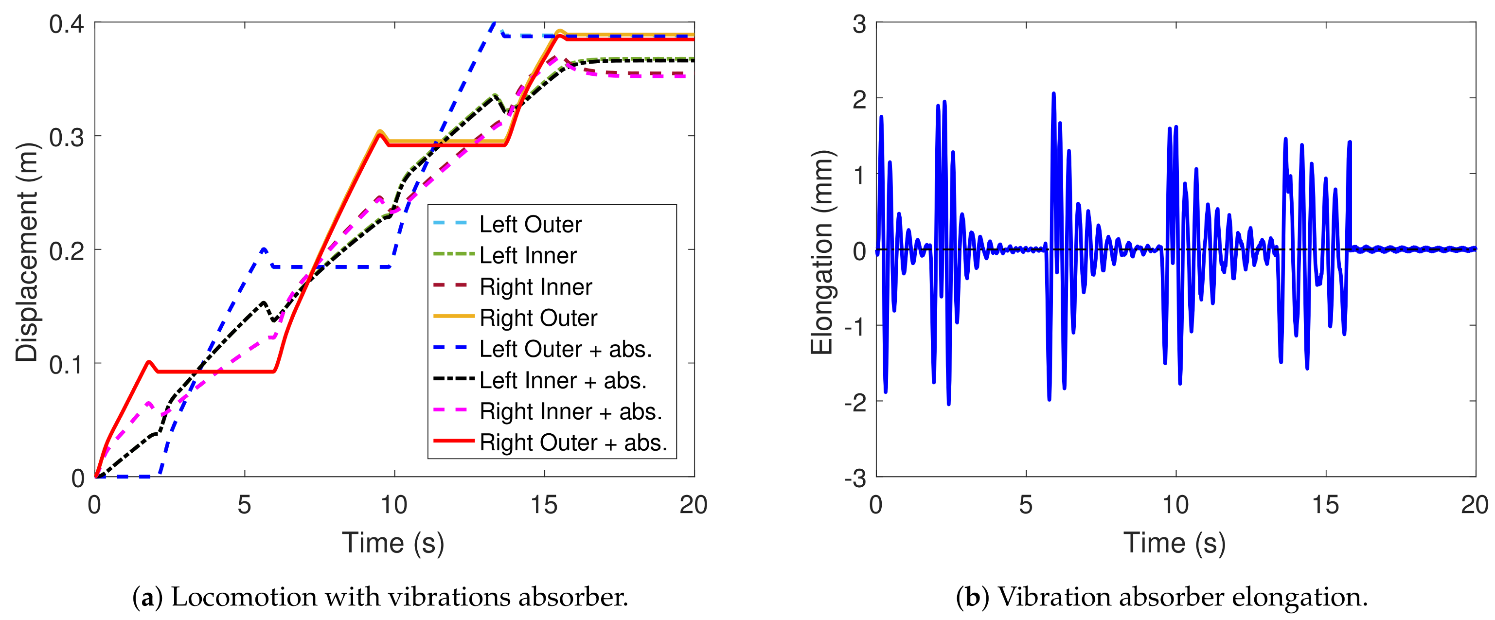
The human-like locomotion is not affected by the proposed modification, and this is visible looking at the robot foot displacements. In Figure 11a, the foot displacements obtained with the improved robot model are compared to the foot displacements of the original design. The two simulations are performed with the same input forces, i.e., the foot engine generate the same torques, and the foot displacements are almost the same in the two simulations. Hence, the dynamic absorber does not affect the locomotion, as it was required by the admissible modification constraints. The elongation of the dynamic vibration absorber spring k a , shown in Figure 11b, is important to verify the dimensions constraint. In the actual simulation, the maximum elongation is less than 3 mm, which gives good confidence in the solution feasibility without increasing the overall robot volume. The constraint regarding the center of gravity position is respected, as well: the Rollo center of gravity in the original design was at 25 cm from the floor, while it is at 25.5 cm considering the additional vibration absorber in the enhanced version.

4.3. Dynamic Vibration Absorber Design

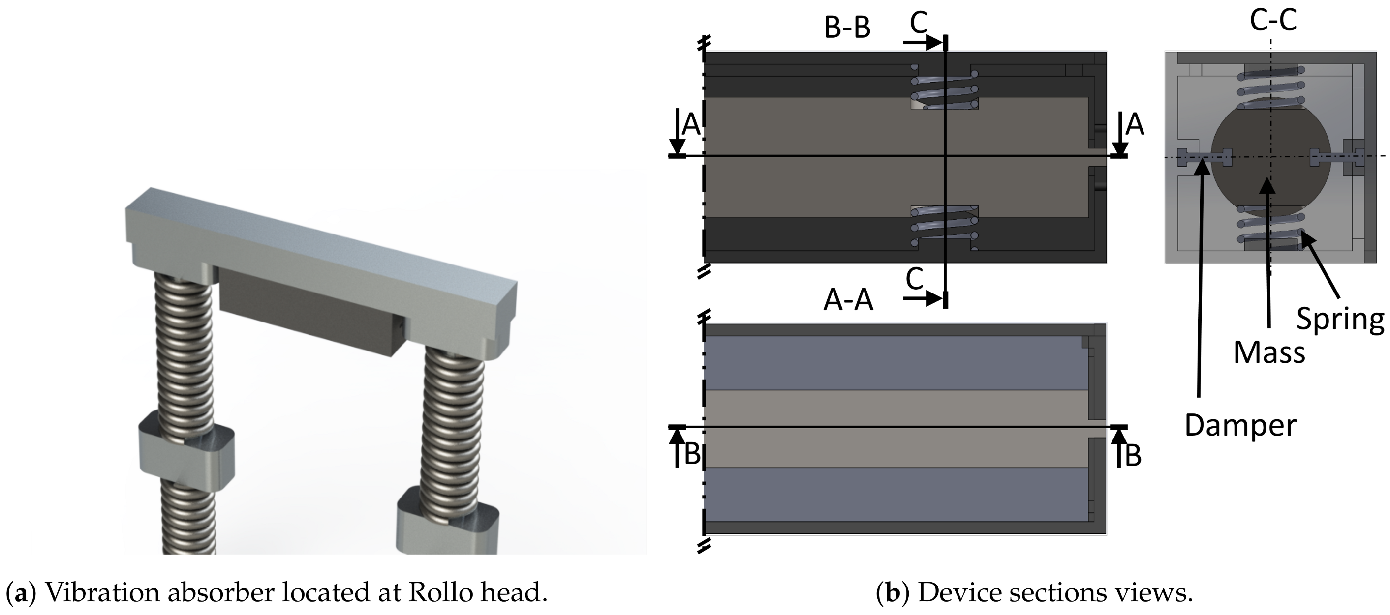
The optimal parameters defined for the dynamic vibration absorber m a , k a , and c a are considered the reference values for designing a real device to be placed on Rollo. The conceived dynamic vibration absorber is an external box fixed under the head supporting beam, as shown in Figure 12a. The device box is composed of two plastic shells on which adequate holes and extrusions are designed to accommodate the dynamic vibration damper elements. The additional mass m a = 0.3 kg is represented by a steel cylinder 12.8 cm long and with diameter 2 cm, shown in Figure 12b. Two pins at the cylinder extremities run inside two horizontal slots obtained on the plastic shell and support its vertical load. The stiffness k a = 158.2 N/m is obtained through 4 helical springs fixed on plastic extruded pins on the shells surface and adequate seats on the steel mass, as shown in Figure 12a. The steel springs’ wire diameter is 1.24 mm, the helix diameter is 8 mm, and the active spires are 3, resulting in a stiffness k s = 39.25 N/m for each spring. The viscous damping coefficient c a is obtained using rubber h-section seals, fixed on both the plastic shells and the vibrating steel mass, as shown in Figure 12b. The length of the rubber seal is adjusted to obtain the correct damping value. Finally, the proposed TMD box can be simply placed on the Rollo robot, without any invasive change to robot design.

5. Conclusions

The oscillation of the head in biped robots is a problem in humanoids research, and it is increased if the robot is flexible or has flexible legs, like the Rollo robot presented in this paper. A simplified model of Rollo was developed in the Lupos environment and shown to be helpful to predict its dynamic behaviour, both in frequency and time domains. The vibration due to the elastic modules bending is compensated by a tuned vibration absorber, which selectively increases damping at the undesired vibration frequency. The proposed solution decreases the vibration amplitude by one order of magnitude so that the head vibrations are quickly attenuated. If necessary, other tuned vibration dampers could be placed simultaneously to reduce the vibration amplitudes due to higher frequency modes. The dynamic vibration absorber device is designed to validate the feasibility of the proposed solution.
This research could be considered as a main contribution towards vibration damping research in flexible-biped locomotion. The same approach could be used on other platforms for increasing the dynamic balance performance of biped robots. Future works could be oriented to define this research problem in a general mode.

6. Patents

G.G. Muscolo, C.T. Recchiuto, “Apparato robotizzato semovente bipede”. Property of G.G. Muscolo and C.T. Recchiuto. Italian Patent N° 102015000049099-ITUB20153452A1. 07/09/2015-7/03/207.

Author Contributions

Conceptualisation, E.B. and G.G.M.; methodology, D.L., E.B., G.G.M.; software, D.L., E.B.; validation, D.L., E.B.; formal analysis, D.L., E.B.; investigation, D.L., E.B., G.G.M.; resources, D.L., E.B., C.T.R., G.G.M.; data curation, D.L., E.B.; writing—original draft preparation, D.L., G.G.M.; writing—review and editing, D.L., E.B., C.T.R., G.G.M.; visualisation, D.L., E.B., C.T.R., G.G.M.; supervision, D.L., E.B., C.T.R., G.G.M.; project administration, E.B., G.G.M.; funding acquisition, E.B., C.T.R., G.G.M. All authors have read and agreed to the published version of the manuscript.

Funding

This research received no external funding.

Conflicts of Interest

The authors declare no conflict of interest.

Abbreviations

The following abbreviations are used in this manuscript:
ZMPzero moment point
TDMtuned mass-spring-dumper
sdofsingle degree of freedom
ALSamyotrophic lateral sclerosis
FEfinite element
FEMfinite element method
FEAfinite element analysis
dofdegree of freedom
EMAexperimental modal analysis
FRFsfrequency response functions
MACXmodal assurance criterion for complex modes shapes
MLMMmaximum likelihood estimation of a modal model
mdofmulti degree of freedom
RMSroot mean square

Appendix A. Tuning of the Flexible Module
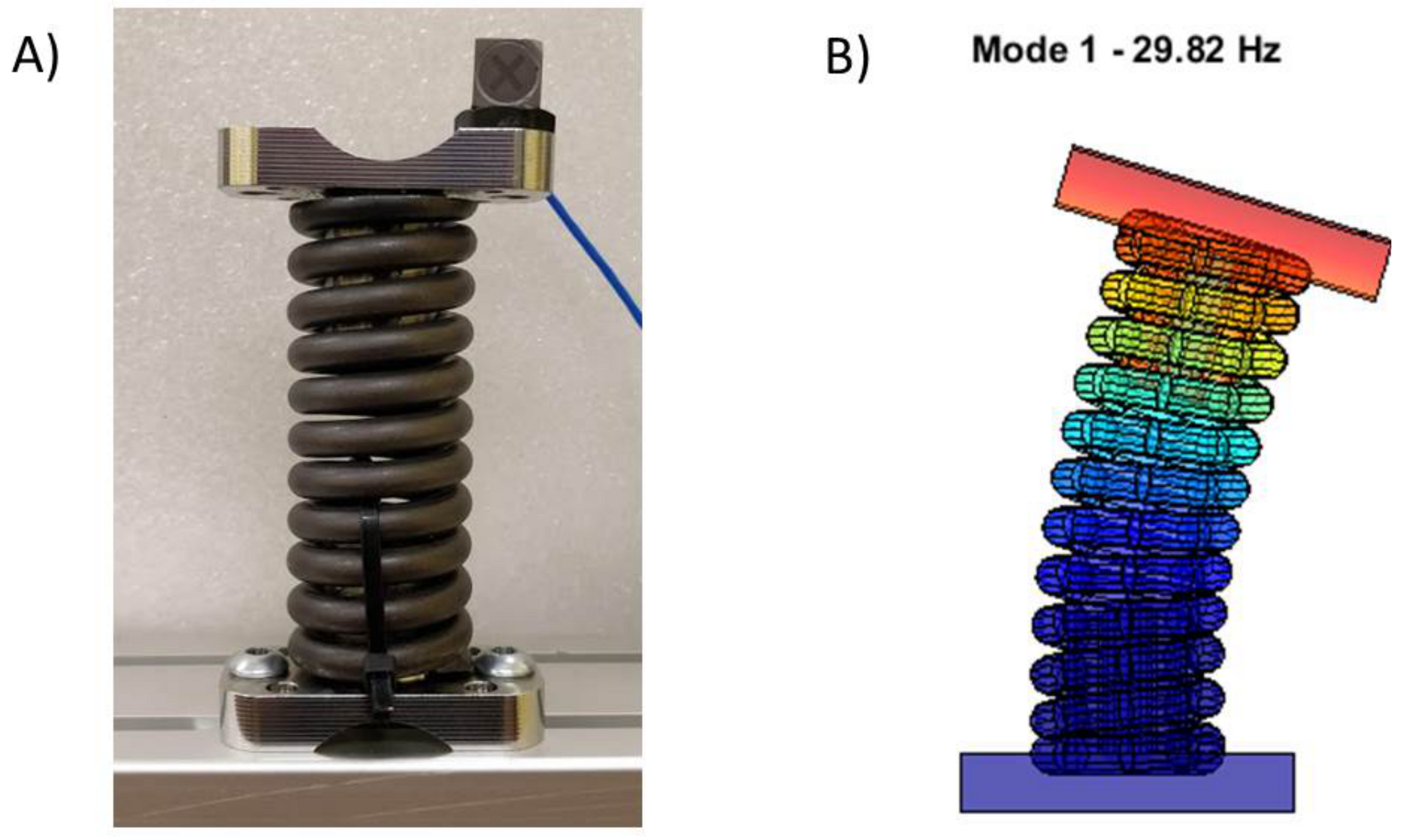
In multibody system dynamics, springs are usually modeled as lumped parameters [53,54,55]; however, in the Rollo architecture, springs are not only elastic elements but mostly structural elements, and their mass can not be neglected. Each flexible modulus is composed of a spring and two steel attachments. The springs have 13 and 15 spires, respectively for the lower and upper modules. A lumped parameter representation of Rollo elastic modules is not enough to reproduce Rollo vibrational behaviour; hence, they are modeled as real springs using the helical spring Lupos library. The library uses 1D Timoshenko beam elements to simulate the spring behaviour, using the geometrical dimensions and material properties. The helical springs are modeled using cylindrical beam elements, with the cross-section diameter equal to the spring wire diameter, wrapped on the helix defined by diameter and pitch of the spires. Each spire of the spring is discretized using eight beam elements. Springs are assembled to the entire structure using steel attachments, as shown in Figure A1A, which are the thick rectangular plate with a cylindrical hollowed extrusion. The external surface of the cylindrical extrusion fits with interference in the internal diameter of the spring helix. In the model, an attachment is represented using a thick rectangular beam, representing the attachment base and a cylindrical beam fitting with the helix spring. The correct simulation of Rollo dynamics requires to know the number of inactive spires. However, the interference fit between the inner diameter of the extremity spires and the steel attachment does not let to understand the number of active spires easily. The number of active spires depends on the amplitudes of the oscillation due to the assembly technique. Since modal analysis holds only for a linear system, which requires small oscillation amplitude, the number of active spires is tuned on the experimental dynamics of the spring alone, under small oscillation amplitude. Experimental tests are performed on a single spring, with lower and upper attachments. The lower part of the spring is fixed, as shown in Figure A1A. The spring is excited using a modal hammer, and the response is measured using a tri-axial accelerometer. Experimental natural frequencies are reported in Table A1. The number of inactive spires required to minimize the difference between experimental and numerical natural frequencies results in two spires for each extremity of the spring. The modal properties of the tuned model, listed in Table A1, agree with the experimental results. The tuned dynamic model of the elastic modulus, which first bending mode shape is shown in Figure A1B, is implemented in the Rollo structural model.
Figure A1. (A) Spring experimental setup, (B) numerical bending mode shape.
Applsci 11 02945 g0a1
Table A1. Experimental and numerical natural frequencies of the fixed–free spring.
ModeDescriptionExp. f n (Hz)Num. f n (Hz)
11st bending29.6–35.029.82–30.45
21st axial95.1693.94
31st torsional105.9897.08
42nd bending187.47–210.32185.9–216.7

Appendix B. Time Domain Simulations Theory

The equation of motion of the robot is represented by:
M x ¨ + C n p + C x ˙ + K x = f , x t = 0 = x 0 , x ˙ t = 0 = v 0
where M and K are respectively the mass and stiffness matrices, defined above. Proportional viscous damping is assumed for the distributed dissipation of the system, modeled through the damping matrix C = T T α M g + β K g T R n , n , where M g , K g and T are defined above and α = 3.31 rad / s and β = 0.0005 s / rad are respectively the mass and stiffness proportional viscous damping coefficients fitting the experimental damping ratios in Table 1 via the damping ratio definition for viscous damped systems ζ i = 1 2 α ω i + β ω i . A non-proportional viscous damping matrix C n p R n , n is also introduced to model the effect of the localized dissipation at the wheel–floor contact. f R n , 1 is the vector of the external forces acting of the system, i.e., the input to the system. x 0 R n , 1 and v 0 R n , 1 are respectively the displacement and velocity initial conditions, and x , x ˙ , x ¨ R n , 1 are respectively the displacements, velocity, and acceleration vectors.
The second order ordinary differential equation in Equation (A1) is written in first order form using the so called Duncan approach [56]:
C n p + C M M 0 x ˙ x ¨ + K 0 0 M x x ˙ = f 0 , x t = 0 = x 0 , x ˙ t = 0 = v 0
or in compact form
A y ˙ + B y = F , y t = 0 = x 0 T v 0 T T
where A , B R 2 n , 2 n , F R 2 n , 1 , and y , y ˙ R 2 n , 1 .
The human-like locomotion of the Robot is simulated imposing alternately the traction longitudinal force to Rollo’s feet, i.e., a time dependent input forces f according to the robot steps. The first order ordinary differential equation Equation (A2) is efficiently solved using the superimposition principle in modal coordinates [42,57], i.e., solving 2 n uncoupled equations in modal coordinates η and then applying direct modal transformation y = ψ η to obtain the system evolution if the physical coordinates x . However, the locomotion simulation is a non-classically damped problem, because of the localized dampers presence at the wheel floor contact. Therefore the exact modal base ψ representing the system has to be obtained solving the eigenvalue problem related to Equation (A3):
s r A + B ψ r = 0
where s r C and ψ r C 2 n , 1 are respectively the rth pole and mode-shape of the system. The system modal matrix to be used in the modal transformation is ψ = ψ 1 , , ψ 2 n . Performing the direct modal transformation, i.e., y = ψ η , and pre-multiplying Equation (A3) with ψ T , it follows:
ψ T A ψ η ˙ + ψ T B ψ η = ψ T F
The A , B -orthogonality theorem [41] guarantees the coefficients matrices in Equation (A5) to be diagonal:
ψ T A ψ = a r , ψ T B ψ = b r
where a r , b r C are the modal constants of each mode shapes, which can be related as s r = b r a r . Thus, Equation (A5) is a set of 2 n uncoupled equations as follows:
η ˙ r s r η r = F ˜ r a r , η r t = 0 = η 0 r , r = 1 , , 2 n
where F ˜ r C and η 0 r C are the rth components of respectively the force vector and the initial condition in modal domain, respectively defined as:
F ˜ = ψ T F , η 0 = 1 / a r ψ T A y 0 ;
Equation (A7) is a first order forced ordinary differential equation, whose solution is obtained as the sum of the homogeneous solution η r h t and a particular solution η r p t obtained from a convolution integral. The time evolution of each modal coordinate is analytically derived as:
η r t = η r h t + η r p t = η 0 r e s r t + 1 a r 0 t F ˜ r e s r τ t d τ , r = 1 , , 2 n
The response in physical coordinates is obtained applying direct modal transformation y = ψ η . This procedure is advantageous because avoiding the integration of the equation of motion of the system (A1) through numerical approaches reduces the computation effort required. Moreover, a model order reduction could be easy implemented in the modal domain, considering only 2 R < 2 n low frequency mode shapes of the modal base, i.e., ψ C 2 n , 2 R .

References

  1. Hosoda, Y.; Egawa, S.; Tamamoto, J.; Yamamoto, K.; Nakamura, R.; Togami, M. Basic design of human-symbiotic robot EMIEW. In Proceedings of the IEEE International Conference on Intelligent Robots and Systems, Beijing, China, 9–15 October 2006; pp. 5079–5084. [Google Scholar] [CrossRef]
  2. Raibert, M.; Blankespoor, K.; Nelson, G.; Playter, R. Bigdog, the rough-terrain quadruped robot. IFAC Proc. Vol. 2008, 41, 10822–10825. [Google Scholar] [CrossRef] [Green Version]
  3. Muscolo, G.G.; Moretti, G.; Cannata, G. SUAS: A novel soft underwater artificial skin with capacitive transducers and hyperelastic membrane. Robotica 2019, 37, 756–777. [Google Scholar] [CrossRef]
  4. De Pina Filho, A. Humanoid Robots: New Developments; IntechOpen: London, UK, 2007. [Google Scholar]
  5. Mombaur, K.; Truong, A.; Laumond, J. From human to humanoid locomotion—An inverse optimal control approach. Auton. Robot. 2010, 28, 369–383. [Google Scholar] [CrossRef]
  6. Dahiya, R.; Metta, G.; Valle, M.; Sandini, G. Tactile sensing - from humans to humanoids. IEEE Trans. Robot. 2010, 26, 1–20. [Google Scholar] [CrossRef]
  7. Alfayad, S.; Tayba, A.M.; Ouezdou, F.B.; Namoun, F. Kinematic synthesis and modeling of a three degrees-of-freedom hybrid mechanism for shoulder and hip modules of humanoid robots. J. Mech. Robot. 2016, 8. [Google Scholar] [CrossRef]
  8. Alexander, R. The gaits of bipedal and quadrupedal animals. Int. J. Robot. Res. 1984, 3, 49–59. [Google Scholar] [CrossRef]
  9. Steffan, E.; Pal, S.; Das, T. Bio-inspired locomotion of circular robots with diametrically translating legs. J. Mech. Robot. 2020, 12. [Google Scholar] [CrossRef]
  10. Alexander, R. Optima for Animals; Princeton University Press: Princeton, NJ, USA, 1996. [Google Scholar]
  11. McGeer, T. Passive dynamic walking. Int. J. Robot. Res. 1990, 9, 62–82. [Google Scholar] [CrossRef]
  12. McGeer, T. Passive Dynamic Biped Catalogue; Experimental Robotics II. Lecture Notes in Control and Information Sciences; Springer: Berlin/Heidelberg, Germany, 1993; pp. 463–490. [Google Scholar]
  13. Pratt, G. Legged robots at MIT: What’s new since Raibert? IEEE Robot. Autom. Mag. 2000, 7, 15–19. [Google Scholar] [CrossRef]
  14. Righetti, L.; Ijspeert, A. Programmable central pattern generators: An application to biped locomotion control. In Proceedings of the 2006 IEEE International Conference on Robotics and Automation, ICRA 2006, Orlando, FL, USA, 15–19 May 2006; pp. 1585–1590. [Google Scholar]
  15. Ijspeert, A. Central pattern generators for locomotion control in animals and robots: A review. Neural Netw. 2008, 21, 642–653. [Google Scholar] [CrossRef]
  16. Vukobratović, M.; Borovac, B. Zero-moment point - thirty five years of its life. Int. J. Hum. Robot. 2004, 1, 157–173. [Google Scholar] [CrossRef]
  17. Ogura, Y.; Aikawa, H.; Shimomura, K.; Kondo, H.; Morishima, A.; Lim, H.; Takanishi, A. Development of a new humanoid robot WABIAN-2. In Proceedings of the 2006 IEEE International Conference on Robotics and Automation, ICRA 2006, Orlando, FL, USA, 15–19 May 2006; pp. 76–81. [Google Scholar]
  18. Muscolo, G.G.; Recchiuto, C.T.; Molfino, R. Dynamic balance optimization in biped robots: Physical modeling, implementation and tests using an innovative formula. Robotica 2015, 33, 2083–2099. [Google Scholar] [CrossRef]
  19. Muscolo, G.G.; Caldwell, D.; Cannella, F. Calculation of the center of mass position of each link of multibody biped robots. Appl. Sci. 2017, 7, 724. [Google Scholar] [CrossRef] [Green Version]
  20. EMIEW 2-Hitachi’s Humanoid Robot, Really Cute and Clever. 2010. Available online: https://www.youtube.com/watch?v=6Jb9oJY0Fe8 (accessed on 23 March 2021).
  21. Dynamics, B. Introducing Handle. 2017. Available online: https://www.youtube.com/watch?v=-7xvqQeoA8c (accessed on 23 March 2021).
  22. Muscolo, G.G.; Recchiuto, C.T. Flexible structure and wheeled feet to simplify biped locomotion of humanoid robots. Int. J. Humanoid Robot. 2016, 14, 1650030. [Google Scholar] [CrossRef]
  23. Muscolo, G.G.; Caldwell, D.; Cannella, F. Multibody dynamics of a flexible legged robot with wheeled feet. In Proceedings of the ECCOMAS Thematic Conference on Multibody Dynamics, Prague, Czech Republic, 19–22 June 2017; pp. 19–22. [Google Scholar]
  24. De Silva, C. Vibration Damping, Control, and Design; CRC Press: Boca Raton, FL, USA, 2007. [Google Scholar]
  25. Gakkai, D. Earthquake Resistant Design for Civil Engineering Structures, Earth Structures and Foundations in Japan; Japan Society of Civil Engineers: Tokyo, Japan, 1960. [Google Scholar]
  26. Bachmann, H.; Ammann, W. Vibrations in Structures: Induced by Man and Machines; Structural Engineering Documents, International Association for Bridge and Structural Engineering; IABSE: Zürich, Switzerland, 1987. [Google Scholar]
  27. Bastow, D.; Howard, G. Car Suspension and Handling; Pentech Press: Budapest, Hungary, 1993. [Google Scholar]
  28. Fuchs, A.; Nijman, E.; Priebsch, H. Automotive NVH Technology; Springer Briefs in Applied Sciences and Technology; Springer International Publishing: Berlin/Heidelberg, Germany, 2015. [Google Scholar]
  29. Ignazio, D.; Ferri, A. Active Control of Aircraft Cabin Noise; Computational and Experimental Methods in Structures; World Scientific Publishing Company: Singapore, 2015. [Google Scholar]
  30. Lisitano, D.; Bonisoli, E.; Mottershead, J. Experimental direct spatial damping identification by the stabilised layers method. J. Sound Vib. 2018, 437, 325–339. [Google Scholar] [CrossRef]
  31. Wang, X.; Yang, B. Transient vibration control using nonlinear convergence active vibration absorber for impulse excitation. Mech. Syst. Signal Process. 2019, 117, 425–436. [Google Scholar] [CrossRef]
  32. Cuvillon, L.; Weber, X.; Gangloff, J. Modal Control for active vibration damping of cable-driven parallel robots. J. Mech. Robot. 2020, 12. [Google Scholar] [CrossRef]
  33. Johnson, C. Design of passive damping systems. J. Vib. Acoust. Trans. ASME 1995, 117, 171–176. [Google Scholar] [CrossRef]
  34. Steffen, V.; Rade, D.; Inman, D. Using passive techniques for vibration damping in mechanical systems. J. Braz. Soc. Mech. Sci. 2000, 22, 363–370. [Google Scholar] [CrossRef]
  35. Maiorino, A.; Muscolo, G.G. Biped robots with compliant joints for walking and running performance Growing. Front. Mech. Eng. 2020, 6, 11. [Google Scholar] [CrossRef]
  36. Spadaro, F.T.; Muscolo, G.G. Compliant joints influence in four-legged robots. Front. Mech. Eng. 2020, 6, 16. [Google Scholar] [CrossRef]
  37. Frahm, H. Device for Damping Vibrations of Bodies. U.S. Patent Application No. 989,958, 18 April 1911. [Google Scholar]
  38. Den Hartog, J. Mechanical Vibrations; Dover Civil and Mechanical Engineering; Dover Publications: Mineola, NY, USA, 2013. [Google Scholar]
  39. Calabrò, R.; Portaro, S.; Manuli, A.; Leo, A.; Naro, A.; Bramanti, A. Rethinking the robotic rehabilitation pathway for people with amyotrophic lateral sclerosis: A need for clinical trials. Innov. Clin. Neurosci. 2019, 16, 11. [Google Scholar]
  40. Bonisoli, E. LUPOS—LUmped Parameters Open Source FEM Code, Politecnico di Torino. Tutorial, 16 January 2021. [Google Scholar]
  41. Maia, N.; Silva, J. Theoretical and Experimental Modal Analysis; Engineering Dynamics Series; Research Studies Press: Somerset, UK, 1997. [Google Scholar]
  42. Géradin, M.; Rixen, D. Mechanical Vibrations—Theory and Application to Structural Dynamics; John Wiley & Sons: Hoboken, NJ, USA, 2015; p. 616. [Google Scholar]
  43. Genta, G. Vibration Dynamics and Control; Mechanical Engineering Series; Springer: New York, NY, USA, 2008. [Google Scholar]
  44. Peeters, B.; Van der Auweraer, H.; Guillaume, P.; Leuridan, J. The PolyMAX frequency-domain method: A new standard for modal parameter estimation? Shock Vib. 2004, 11, 395–409. [Google Scholar] [CrossRef]
  45. El-Kafafy, M.; Peeters, B.; Guillaume, P.; De Troyer, T. Constrained maximum likelihood modal parameter identification applied to structural dynamics. Mech. Syst. Signal Process. 2016, 72–73, 567–589. [Google Scholar] [CrossRef]
  46. Vacher, P.; Jacquier, B.; Bucharles, A. Extensions of the MAC criterion to complex modes. In Proceedings of the International Conference on Noise and Vibration Engineering, ISMA, Leuven, Belgium, 20–22 September 2010; pp. 2713–2726. [Google Scholar]
  47. Ghandchi Tehrani, M.; Mottershead, J.E.; Shenton, A.T.; Ram, Y.M. Robust pole placement in structures by the method of receptances. Mech. Syst. Signal Process. 2011, 25, 112–122. [Google Scholar] [CrossRef]
  48. Lisitano, D.; Jiffri, S.; Bonisoli, E.; Mottershead, J.E. Experimental feedback linearisation of a non-smooth nonlinear system by the method of receptances. Math. Mech. Solids 2018. [Google Scholar] [CrossRef] [Green Version]
  49. Jiffri, S.; Fichera, S.; Mottershead, J.E.; Da Ronch, A. Experimental nonlinear control for flutter suppression in a nonlinear aeroelastic system. J. Guid. Control. Dyn. 2017, 40, 1925–1938. [Google Scholar] [CrossRef]
  50. Dal Borgo, M.; Ghandchi Tehrani, M.; Elliott, S.J. Active nonlinear control of a stroke limited inertial actuator: Theory and experiment. J. Sound Vib. 2020, 465. [Google Scholar] [CrossRef]
  51. Camperi, S.; Ghandchi Tehrani, M.; Elliott, S.J. Local tuning and power requirements of a multi-input multi-output decentralised velocity feedback with inertial actuators. Mech. Syst. Signal Process. 2019, 117, 689–708. [Google Scholar] [CrossRef] [Green Version]
  52. Randall, S.; Halsted, D.; Taylor, D. Optimum vibration absorbers for linear damped systems. J. Mech. Des. Trans. ASME 1981, 103, 908–913. [Google Scholar] [CrossRef]
  53. Cirelli, M.; Valentini, P.; Pennestrì, E. A study of the non-linear dynamic response of spur gear using a multibody contact based model with flexible teeth. J. Sound Vib. 2019, 445, 148–167. [Google Scholar] [CrossRef]
  54. Richiedei, D.; Trevisani, A. Updating of finite element models for controlled multibody flexible systems through modal analysis. In Computational Methods in Applied Sciences; Springer: Berlin/Heidelberg, Germany, 2020; Volume 53, pp. 264–271. [Google Scholar] [CrossRef]
  55. Bosmans, J.; Blockmans, B.; Croes, J.; Vermaut, M.; Desmet, W. 1D-3D nesting: Embedding reduced order flexible multibody models. In Conference for Wind Power Drives; CWD Aachen: Aachen, Germany, 2019; pp. 523–537. [Google Scholar]
  56. Foss, K. Coordinates Which Uncouple the Equations of Motion of Damped Linear Dynamic Systems; Technical Report; Massachusetts Institute of Technology Aeroelastic and Structures Research Laboratory: Cambridge, MA, USA, 1956. [Google Scholar]
  57. Bonisoli, E.; Lisitano, D.; Conigliaro, C. Experimental-numerical comparison of contact nonlinear dynamics through multi-level linear mode shapes. In Nonlinear Structures and Systems; Springer: Berlin/Heidelberg, Germany, 2019; Volume 1, pp. 263–271. [Google Scholar] [CrossRef]
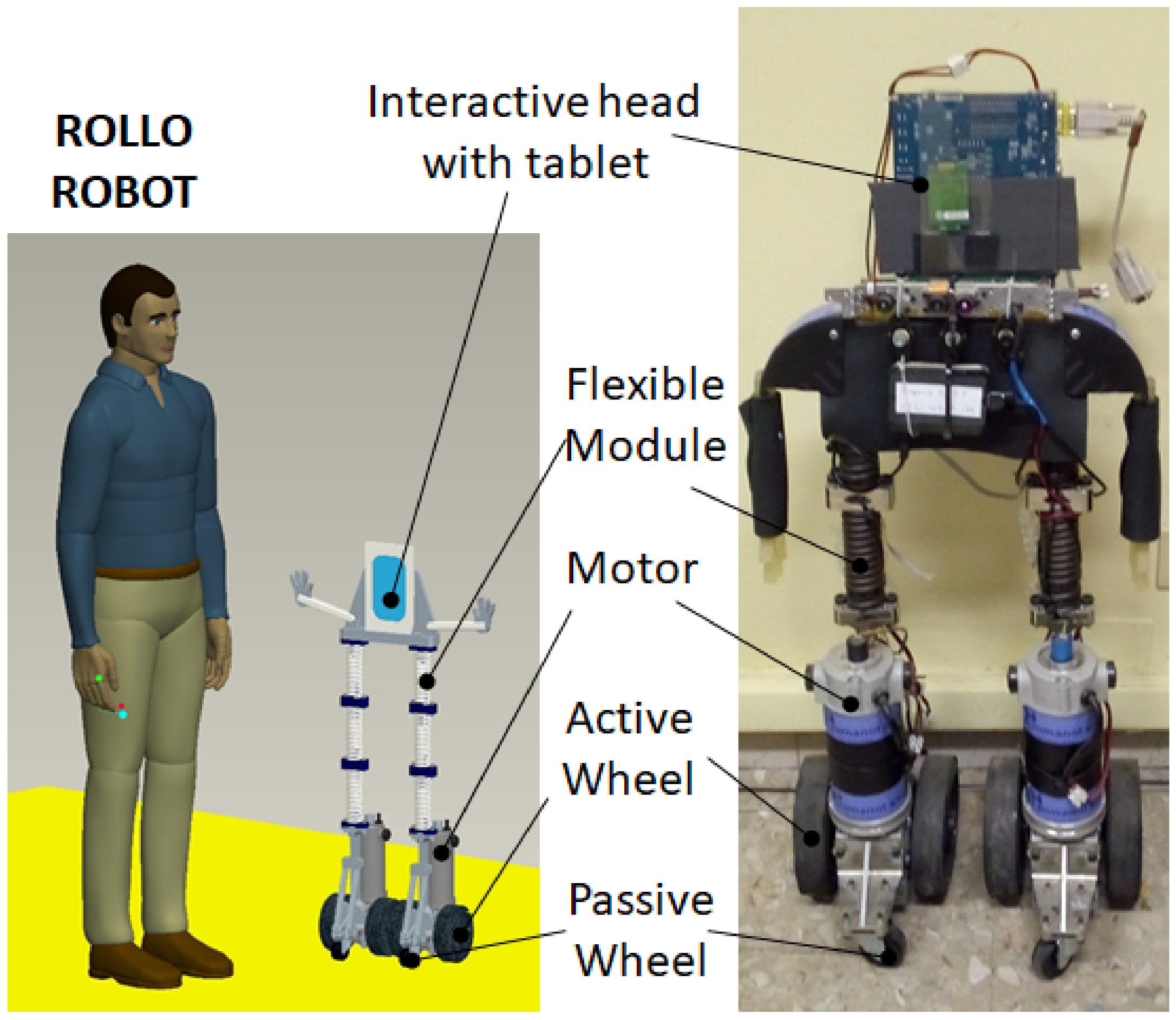
Figure 1. Flexible-wheeled biped robot Rollo.
Applsci 11 02945 g001
Figure 2. Model of Rollo in Lupos environment.
Applsci 11 02945 g002
Figure 3. Robot mode shapes: numerical (left, solid colours) and experimental (right, transparent colours).
Applsci 11 02945 g003
Figure 4. (A) Experimental setup and accelerometer locations, (B) excited nodes.
Applsci 11 02945 g004
Figure 5. MACX between experimental and numerical mode shapes.
Applsci 11 02945 g005
Figure 6. Simulation of Rollo implementing human-like locomotion.
Applsci 11 02945 g006
Figure 7. Rollo wheels displacement and applied forces during human-like locomotion.
Applsci 11 02945 g007
Figure 8. Acceleration at the supporting head beam during locomotion.
Applsci 11 02945 g008
Figure 9. Optimisation of the acceleration at the supporting head beam during locomotion.
Applsci 11 02945 g009
Figure 10. Acceleration of the supporting head beam during human-like locomotion using the dynamic adsorber.
Applsci 11 02945 g010
Figure 11. Wheels displacement and absorber elongation during human-like locomotion using the dynamic absorber.
Applsci 11 02945 g011
Figure 12. Dynamic vibration absorber design.
Applsci 11 02945 g012
Table 1. Rollo numerical natural frequencies and experimental natural frequencies and damping ratios.
ModeDescriptionNum. f n (Hz)Exp. f n (Hz)Exp. ζ (%)
11st legs bending out of phase lateral direction0.5270.49254.92
21st legs torsion in phase4.0632.7966.78
31st legs torsion out of phase4.1474.7151.51
41st legs axial out of phase6.4715.3165.94
52nd legs bending in phase7.3568.7443.91
62nd legs bending out of phase lateral direction8.0087.9642.28
71st legs axial in phase8.1757.4313.62
82nd legs bending out of phase motion direction10.0511.915.01
92nd legs bending in phase motion direction12.6417.956.38
103rd legs bending in phase lateral direction23.9928.675.60
Publisher’s Note: MDPI stays neutral with regard to jurisdictional claims in published maps and institutional affiliations.