Article

Analysis and Design of a Leading Edge with Morphing Capabilities for the Wing of a Regional Aircraft—Gapless Chord- and Camber-Increase for High-Lift Performance

1
Fraunhofer LBF, 64289 Darmstadt, Germany
2
Fraunhofer IBP, Nobelstraße 12, 70569 Stuttgart, Germany
3
Fraunhofer EMI, Ernst-Zermelo-Straße 4, 79104 Freiburg, Germany
*
Author to whom correspondence should be addressed.
Appl. Sci. 2021, 11(6), 2752; https://doi.org/10.3390/app11062752
Submission received: 30 January 2021 / Revised: 10 March 2021 / Accepted: 15 March 2021 / Published: 19 March 2021
(This article belongs to the Special Issue Smart Aircraft Morphing Technologies)

Abstract

:
In order to contribute to achieving noise and emission reduction goals, Fraunhofer and Airbus deal with the development of a morphing leading edge (MLE) as a high lift device for aircraft. Within the European research program “Clean Sky 2”, a morphing leading edge with gapless chord- and camber-increase for high-lift performance was developed. The MLE is able to morph into two different aerofoils—one for cruise and one for take-off/landing, the latter increasing lift and stall angle over the former. The shape flexibility is realised by a carbon fibre reinforced plastic (CFRP) skin optimised for bending and a sliding contact at the bottom. The material is selected in terms of type, thickness, and lay-up including ply-wise fibre orientation based on numerical simulation and material tests. The MLE is driven by an internal electromechanical actuation system. Load introduction into the skin is realised by span-wise stringers, which require specific stiffness and thermal expansion properties for this task. To avoid the penetration of a bird into the front spar of the wing in case of bird strike, a bird strike protection structure is proposed and analysed. In this paper, the designed MLE including aerodynamic properties, composite skin structure, actuation system, and bird strike behaviour is described and analysed.

1. Introduction

Currently, the aviation industry is developing quieter and more efficient aircraft to reach the environmental goals of Flightpath 2050 [1,2]. New technologies are expected to allow a 75% reduction in CO2 emissions per passenger kilometre and a 90% reduction in NOx emissions. The perceived noise emission of flying aircraft is to be reduced by 65% [3]. The investigation and development of new high-lift devices provide not only an improvement of aerodynamics, but also a positive effect on the emission of noise and pollutants. Over the last years, the volume of air traffic has increased approx. 5% per annum. This means that air traffic will considerably increase within the next 20 years. In order to sustain the CO2 and noise emissions, they have to be significantly reduced. Traditional high-lift devices, such as Krueger flaps or slats, provide an increase of the aerodynamic lift, but also an increase of the noise emission [4,5]. This increase in noise is due to the presence of a gap between the high-lift device and the main wing [6]. If a gapless high lift device can be designed, this source of noise emission vanishes, which may in turn reduce the noise footprint of the aircraft. One way forward is the development of gapless, morphing high-lift devices. Additionally, gapless, morphing high-lift devices could be an enabler for natural laminar flow (NLF) [7,8]. Therefore, for several decades, the aviation industry, as well as research institutions, have been investigating morphing high-lift devices. Some examples are briefly described below.
Communier and co-workers experimentally and numerically demonstrated that morphing leading edge concepts can potentially replace traditional leading-edge devices in terms of their aerodynamic properties [9]. However, for the design of a morphing leading edge, the aerodynamic efficiency is not solely important. The MLE designed here was intended to be placed on an unmanned aerial vehicle (UAV). For this slow-flying UAV, the polymer skin was designed in a way that it did not contribute to the load carrying capability of the wing. However, for larger aircraft operating at higher velocities, the structural aspects of the skin, and in particular the fluid-structure interaction, should not be forgotten [8].
Within the scope of the European project “Smart high lift devices for next generation wings” (SADE) between 2008 and 2012 diverse concepts for deformable leading and trailing edge were considered. For the leading edge, approaches with aeroelastic effects, selective deformable structures with frames, as well as innovative actuator concepts were investigated [10]. Within SADE, Morishima tried to design a MLE with a carbon fibre reinforced composite skin for an A320 type aircraft. However, Finite Element simulations showed that the particular stacking sequences selected in the Cranfield design were not capable of withstanding the high aerodynamic loads imposed on the MLE. Therefore, the skin material was changed to aluminium [5].
Peel and co-workers developed a small-scale morphing leading edge demonstrator featuring a carbon fibre reinforced composite (CFRP) skin with stacking sequence [+10/−10]ns. The actuation concept makes use of filament-wound rubber muscles [11].
The German Aerospace Centre (DLR) has been investigating adaptive structures for several years, where the focal point is research on a suitable skin to reach the requested deformation. Within the project “Smart Leading Edge Device” (SmartLED), DLR realised a concept for a gapless leading edge in a 1:1 scale demonstrator. Glass fibre material with varied thickness of the laminate (ply drop-off) was used in conjunction with omega stringers, and an actuation kinematic was designed [10]. Within the framework of the “Smart Fixed Wing” platform of the European research programme “Clean Sky”, DLR developed flexible morphing skins composed of glass fibre-reinforced composite and a layer of elastomer [12].
Between 2011 and 2015, several morphing structures were developed, manufactured, and tested within the European project “Smart Intelligent Aircraft Structures (SARISTU)”. These included a morphing trailing edge [13], a morphing winglet [14,15], and a morphing leading edge [16,17]. The MLE developed within this framework follows the concept of an enhanced adaptive droop nose with a glass-fibre reinforced composite skin. The demonstrators were tested in the wind tunnel as well as subjected to bird impact loading to demonstrate the aerodynamic effectiveness and safety of the design. Besides the aerodynamic and structural design, the SARISTU project team also developed shape sensing systems based on Fiber Bragg Grating sensors [18], which have also been used by Ma and Zhen [19] as well as Święch [20]. Additionally, load monitoring systems employing optical fibres and strain gauges have been developed within SARISTU [21]. These technologies help to verify that the MLE is operating within the operational window.
TU Delft has also been working on the development of a morphing leading edge within the “Green Regional Aircraft” platform of the European Project “Clean Sky”. The approach followed by TU Delft foresees a deformable aluminium skin, which is actuated by a Linak LA23 series linear actuator [22]. It was demonstrated that the system is capable of reaching the target shapes with sufficient accuracy. Vasista et al. [23] developed a glass fibre reinforced plastics (GFRP) skin MLE, which is actuated by one harmonic drive rotational actuator per kinematic rib. Whilst the system showed to work satisfactorily, the authors commented that one of the big future challenges would be to reduce the structural mass of the system. An alternative approach to classical actuation systems is the use of shape memory alloys (SMA) for actuation, as successfully demonstrated by Ameduri [24].
Fraunhofer has also investigated efficient aviation structures within the “Green Regional Aircraft” platform of the European Project “Clean Sky”. In this context, Fraunhofer LBF developed, manufactured, and tested a 1:1 scale smart morphing leading edge demonstrator. It was realised as a full-scale morphing leading edge of 3 m span for ground demonstration. The setup was also validated in a climate wind tunnel under icing conditions. Besides, the electromechanical morphing actuation system and additional technologies were integrated in the demonstrator like optical fibre Bragg grating sensors, for shape reconstruction and strain measurement as well as an ice protection system based on carbon nanotubes. Figure 1 shows the leading-edge demonstrator in the climate wind tunnel [25].
Improvement of aerodynamic properties without deterioration of acoustic properties can be achieved with adaptive and gapless high-lift devices. However, this kind of device is not established in series production aircrafts, because of the complex requirements regarding this sort of technology. They must have enough stiffness to carry the aerodynamic loads as well as the flexibility to reach the different desired aerofoils for the wing [26]. Of course, the leading edge (LE) design in these cases has to avoid a gap in the connection with the wing.
De Gaspari et al. [27] have demonstrated that the development of a morphing leading edge with relevance for the aeronautical industry is a very complex and thus challenging task covering several, sometimes rivalling, disciplines, and design objectives. Some of the main aspects to be considered during the development of a morphing leading edge are summarized below:
  • Aerodynamic performance;
  • deformation capability of the skin material;
  • structural integrity including fatigue and impact loading;
  • actuation concept;
  • low structural weight;
  • mounting concept.
Whilst there have been many efforts to address individual aspects of a morphing leading-edge design, only a few works have addressed the full picture. In these cases, the skins were either made from aluminium [5,23] or GFRP [17,27]. However, none of these broad approaches described the development process of a morphing loading edge with CFRP skin. Following a holistic design approach, Fraunhofer LBF in collaboration with Fraunhofer IBP, Fraunhofer EMI, and Airbus have developed a morphing leading edge (MLE) with gapless chord- and camber-increase for high-lift performance within the framework of Clean Sky 2. In the present paper, the proposed design of the MLE is described and analysed. Section 2 describes the method and results of the CFD analysis performed on target aerofoils for cruise and high-lift. In Section 3, the design of the composite structure including skin material and stringers are described. The actuation system employed for morphing the structure is described in Section 4. Section 5, Section 6, Section 7 and Section 8 address further relevant aspects for the proposed morphing device such as fatigue test of the skin material, the design of a gap closure device, the proposed mounting process, and bird strike analysis.

2. CFD Analysis

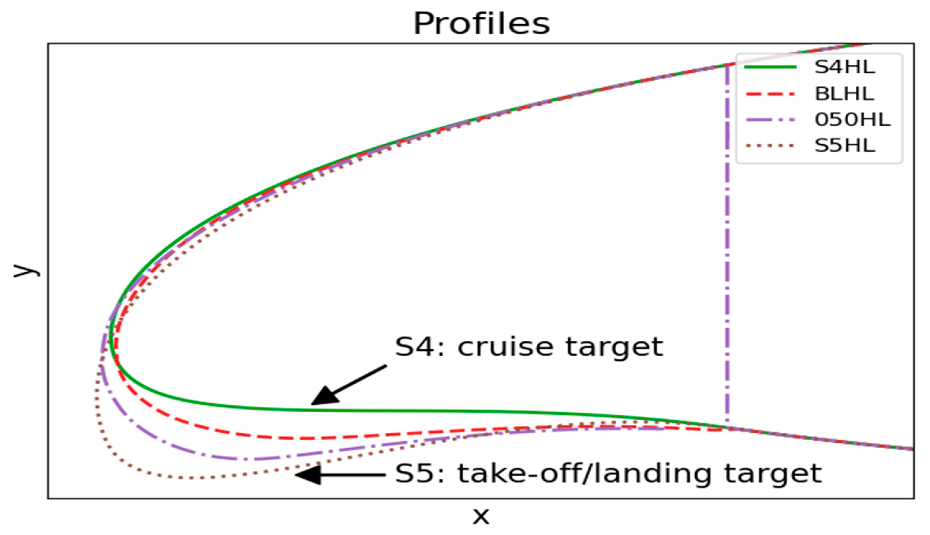
2.1. Analysed Airfoils of the Morphing Wing

Depending on the current flight condition the aerofoil of an aircraft wing has to meet different requirements. In cruise, a low drag is required together with a lift coefficient that corresponds to aircraft weight at cruise velocity. For take-off and landing, a maximum lift coefficient is required in order to reduce take-off/landing velocity contributing to shorten required runway length as well as to reduce perceived noise on the ground. Increasing the lift coefficient is possible by increasing the chord and camber of an aerofoil, but for achieving low drag at cruise, lower values of chord and camber are desired. The MLE allows us to switch between an aerofoil with high chord and camber, and another aerofoil with lower drag at cruise. The aerofoils and flight conditions considered here are for a regional turboprop aircraft with a capacity of approx. 40 passengers, 26 m span, a max. take-off weight of 20 t, and a cruise speed of 180 m/s. This kind of plane typically does not use high lift devices at the leading edge up to now.
To confirm the aerodynamic effect of the MLE, four aerofoil profiles having different LE shapes were analysed, comparison see Figure 2. Aerofoil S4 is the target aerofoil for cruise, aerofoil S5 is the one for take-off and landing with increased chord and increased camber. Additionally, it was analysed whether intermediate aerofoils, which occur due to the implemented actuation system during the morphing process, are aerodynamically feasible. A monotonic change of lift and drag is required during the shape transition. For this purpose, the two intermediate baselines, called BL and 050 between S4 and S5, have been considered. Suffix HL implies that each profile has a deployed trailing edge (TE) flap for analyses in the high-lift condition. For CFD analysis in this condition, the original single Fowler flap of the prototype wing, which the MLE development is based on, was used.

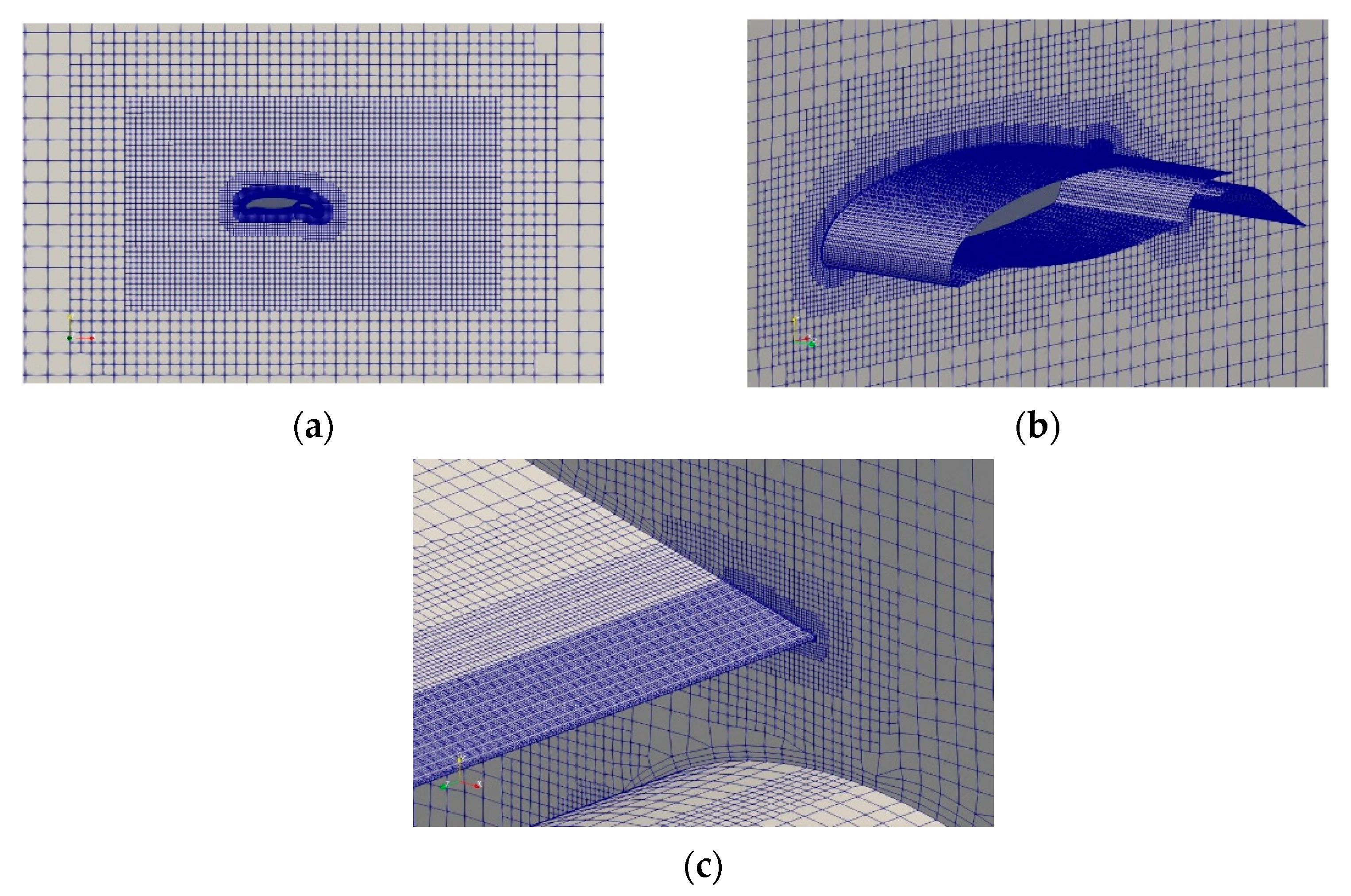
2.2. Details of CFD Analysis

Stationary Reynolds-averaged Navier-Stokes (RANS) simulation was performed using a k-ω shear stress transport (SST) turbulence model [29]. The wall functions were used to do so-called high Re-type flow simulation. In the project, the cruise condition was defined as 240 knots (134 m/s) flow velocity and the standard atmosphere at an altitude of 25,000 feet (air density ⍴ = 0.549 kg/m3). The landing condition was defined as 140 knots (72 m/s) flow velocity and the sea-level atmosphere (⍴ = 1.23 kg/m3). The Reynolds number per 1 m amounts to 1.42 × 10⁷ and 1.47 × 10⁷ for cruise and landing conditions, respectively.
The 2D profiles in Figure 2 were first extruded by 1 m along the span-wise direction. Each of them was then placed in a computational domain of 80 m × 80 m × 1 m. The periodic boundary condition is imposed on both ends in order to do 3D analysis by assuming infinite span length. In this domain, a hexahedral-dominant mesh was generated with 9-step refinement towards the aerofoil. The element size was approximately reduced from 1 m to 2 mm. The entire surface of the aerofoil was covered with 3 boundary layers. The total number of cells was about 1.7 million. The y+ on the aerofoil was confirmed to be between 30 and 300 to let the wall functions properly work. The generated 3D CFD mesh for profile S5HL is shown in various view angles in Figure 3. The analysis was carried out using the incompressible stationary flow solver simpleFoam provided by OpenFOAM.

2.3. Analysis of Lift and Drag

Lift coefficients cl calculated for the high-lift profiles are plotted as functions of the angle of attack (AoA) in Figure 4’s left hand side. In general, the cl increases with the AoA. At a certain angle, stall occurs and the cl suddenly drops. As the LE is lowered from S4HL to S5HL, the stall is delayed to higher stall angles. The maximum values of lift coefficient cl,max and stall angles of the high-lift profiles are listed in Table 1. By changing the profile from S4HL to S5HL, cl,max is increased by 14% from 2.80 to 3.06. The stall angle is also increased from 14.2 to 16.4 degrees.
The stall can also be found in the plots of the drag coefficient cd in Figure 4’s right hand side; these suddenly increase at the respective stall angles. The difference in cd among the profiles before the stall is minor. For the AoA larger than 4 degrees, cd is reduced as the LE is lowered. For the AoA between 0 and 4 degrees, cd of S5HL is slightly higher than cd of S4HL (2.4% at AoA = 2 degrees).

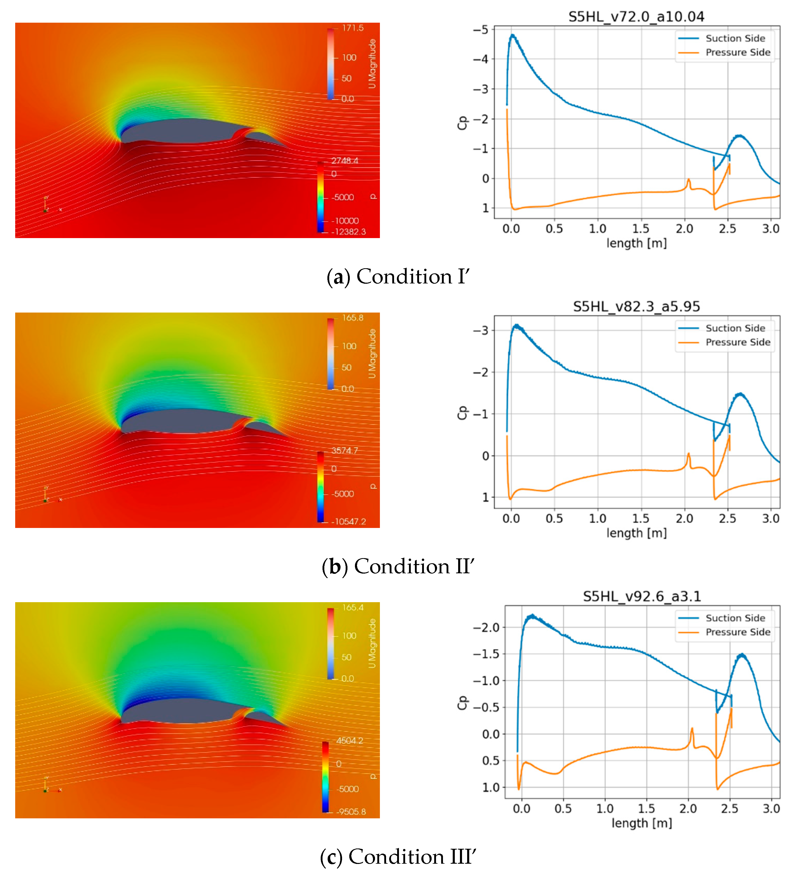
2.4. Analysis of Pressure, Flow, and cp Distributions

To estimate the largest aerodynamic load on the profiles, extreme flight conditions were first defined based on the load factor Nz: For cruise profiles with retracted trailing edge, three conditions for Nz = 2.5 (climb) and one for Nz = 1 (level flight), for high-lift profiles with extended trailing edge, three conditions for Nz = 2.0 (climb). These are listed in Table 2.
In these extreme conditions, 2D CFD analyses were carried out. The simulated pressure and flow (left hand side) and cp distribution or dimensionless pressure normalized by dynamic pressure (right hand side) around cruise profile S5 are shown in Figure 5. Those around high-lift profiles S5HL are shown in Figure 6. The maximum suction on the upper side of four profiles S4, S5, S4HL, and S5HL represented by cp and the actual pressure in kPa are listed in Table 3. These data were used for examining required strength, stiffness, and actuation forces for the morphing system being developed, see Section 4.2.
From these pressure distributions, the following conclusions were drawn. Suction on the upper side near the LE is increased along with AoA. Namely, the largest suction occurs in condition I for the cruise profiles and in condition I′ for the high-lift profiles. The suction peak is located at the leading edge where the highest velocity occurs due to the deflection of the flow direction induced by the aerofoil. At level flight or in condition IV, a large suction peak occurs just under the stagnation point on the lower side. This is especially prominent for profile S5HL having the fully lowered LE. This is again because of large acceleration of the flow turning around this point. On the other hand, the positive cp peak occurs at the stagnation point. The value of this peak, which is nearly 1, implying dynamic pressure, is independent of the AoA.

3. Design of the Skin and the Stringers

3.1. Material Selection and Design of the Skin

A crucial task in designing a morphing leading-edge system is the design of the skin including material selection and stringer layout. On the one hand, the skin needs to provide high deformability in order to be able to morph into the positions S4 (cruise) and S5 (high-lift), see Figure 2. On the other hand, the skin has to meet competing requirements regarding strength and stiffness. As shown in Section 2.4, the leading edge is the region, where the highest aerodynamic loads occur, compared to other regions of the wing. Furthermore, the contour-length of S5 is 7.7% longer than that of S4. This elongation cannot be realised by elastic straining of conventional composite materials (or metals), especially since cyclic deformation has to be endured over the service life. Thus, an alternative solution using a sliding contact is selected in order to address the length difference, see Section 6. It is positioned at the lower side of the MLE so that C2-continuity at the upper surface of the MLE is not affected. The contact position is carefully designed so that it is in the region of the favourable pressure gradient where flow separation is less likely to occur, and thus does not deteriorate the aerodynamic performance.
Morphing from S4 to S5 was therefore expected to be realised by pure bending of the skin and without any membrane strain. Under these conditions, one surface of the skin is compressed (negative strain) while the other is stretched (positive strain), and the absolute values of strain on both sides are equal so that the overall length in any direction does not change. The change of curvature of the MLE’s skin due to morphing is given by the two target shapes S4 and S5. The bending stiffness of the skin should be as low as possible to limit the forces needed for actuation and maintain a low overall weight of the system. At the same time, however, its bending stiffness must be sufficient to limit the deviation from the target shapes under the relevant aerodynamic pressure distributions computed by 2D-CFD, see Section 2.4. While this is largely achieved by means of span-wise stringers, the areas between the stringers still require a certain bending stiffness so as not to bulge in- or outward under the pressure distribution. In a first step towards material selection, a simplified finite element model of the skin consisting of shell elements and assuming isotropic material was therefore used to identify a suitable distribution of the bending stiffness along the contour. The limit for acceptable displacement of the skin perpendicular to its original surface due to aerodynamic loads was set to 1 mm. The thickness in the different regions of the skin was adjusted to meet this requirement and to approximate the target shapes as closely as possible. After the distribution of the bending stiffness along the contour had thus been determined, generic composite laminates (different ply-materials and lay-ups) were analysed by means of Classical Laminate Theory (CLT) and Puck’s failure criterion [30] to determine their respective bending stiffness and bending limit, i.e., the allowable curvature change with respect to avoiding failure. Material data (elastic properties and uniaxial strengths) for typical glass- and carbon-fibre reinforced plies (unidirectional and woven; the database gave values for specific combinations of fibres, resins, and fibre-volume-fractions) were taken from the database of a commercial CLT-software (ESACOMP). Different laminates (all laminates symmetric and balanced, fibre orientations between +/−5° and quasi-isotropic) and with different thicknesses (achieved by repetition of the basic symmetric and balanced laminates) were defined for each ply material and thus analysed. The failure criterion considers the stresses occurring in each ply of the laminate using a failure envelope defined by interpolation of the uniaxial strength values. It yields the inverse reserve factor (IRF), which assumes values equal to or greater than zero. If the IRF reaches or exceeds 1, failure of the ply is assumed. The investigations described above show that laminates made of unidirectional plies reinforced by high-strength or intermediate-modulus carbon fibres provide the necessary combination of properties. However, since the “typical” materials mentioned in the database usually do not directly correspond to commercially available materials, a material type with similar properties then had to be identified that can actually be obtained from suppliers. This led to the selection of IM/8552 carbon fibre [28] for the design of the MLE. This is a “prepreg” material, i.e., the fibres of the semi-finished product stacked to make the laminate are already impregnated (pre-impregnated) by a specific amount of resin. Apart from being a unidirectional intermediate-modulus carbon fibre material which is certified for aviation use, its material properties were readily available in the literature. All these aspects were relevant with respect to its selection. By applying the CLT and Puck’s failure criterion as described above and using the available material properties, it could easily be verified that the achievable combinations of bending stiffnesses and strengths of laminates made of the selected material are suitable for the present application.
Tailoring the stiffness of the MLE skin along the contour was achieved by suitable composite laminate lay-ups, varying the skin thickness by ply drop-offs in the laminate. These were determined in another iterative process based on finite element analysis (FEA) of the structure. Models consisted of linear shell elements (ABAQUS element type S4R, i.e., with reduced integration) with displacement boundary conditions imposed at the top edges of the stringers. The upper edge (approximately parallel to the span-wise direction) of the skin-contour, where it would be fastened to the wing’s front spar, was fixed in all directions (translational and rotational), and the aerodynamic pressure distribution for the respective flight condition (cruise or high-lift) was applied to the outer surface of the skin. The solutions were obtained using an implicit solver and considering geometric non-linearity. This way, the reaction forces occurring at the locations of the displacement boundary conditions are equivalent to the forces applied by an actuation system holding the skin in the required shape under the respective aerodynamic pressure load. Lay-ups were manually modified, and the resulting stresses due to morphing and aerodynamic pressure loads were analysed by the FEM. Subsequently, the IRF according to Puck’s failure criterion as well as the deviation from the target shapes were determined from the FE-solution. Based on these, further modifications of the lay-ups were made, and the process repeated until a suitable solution had been found. A simplified flow-chart of the process for defining the skin laminate is shown in Figure 7.
Tailoring is essential, because the bending strain occurring in the composite plies on the inside and outside surfaces of the laminate is proportional to the laminate thickness as well as the local change of curvature between S4 and S5. Assuming that the target shapes are approximated as intended, increasing the stiffness by adding plies thus also increases the ply stresses, which may then lead to failure. The iterative process described above considers the IRF (strength related; becomes more critical as thickness increases because surface strains increase) as well as the approximation of the target shapes (stiffness related; becomes less critical as thickness increases because aerodynamic loads cause less deviation from the target shapes) so that both aspects are addressed adequately. The objective of stiffness tailoring therefore was to identify the laminate providing just enough bending stiffness to withstand deformation under the aerodynamic loads while being as thin and compliant as possible to reduce actuation forces, weight, and surface-strains. Moreover, fibres should be oriented mainly in the direction of the bending strains to provide the required strength. Since span-wise bending stiffness is provided by the stringers (see Section 3.2), this led to a skin laminate with fibres mostly oriented along the contour, i.e., approximately parallel to the flight-direction. Of course, fibre orientation varies slightly between the plies to prevent splitting of the laminate. The skin of the MLE was divided into seven regions depending on the necessary stiffness and deformation capabilities. Apart from providing span-wise bending stiffness, the stringers are also used as attachment points for the actuation system [28].

3.2. Selection and Design of the Stringers

The aerodynamic surface of the MLE is provided by the above-mentioned skin of CFRP. Its laminate was designed with comparatively low bending stiffness in the circumferential direction, i.e., along the cross-section contour, to allow the change of shape required for the morphing function. In the span-wise direction, however, considerable bending stiffness is required to limit the deformation of the contour due to the aerodynamic loads. Otherwise, the target shapes would not be met and the aerodynamic performance of the MLE would not be acceptable. Therefore, the skin was stiffened by additional span-wise stringers. Depending on how the stringers are joined to the skin, they could lead to a local stiffening of the skin and thus to uneven deformation of the MLE, which would also reduce the aerodynamic performance.
Figure 8 schematically shows the leading-edge contours in the cruise and high-lift configurations (Figure 8 left) as well as the implied change of curvature and positioning of the stringers along the cross-sections’ contour (Figure 8 right). The stringer locations were defined where the change in curvature is minimal, limiting the effect of any local stiffening they may cause.
As shown in Figure 9, the stringers are formed by the inner part of the skin-laminate itself. While this is more complicated with respect to manufacturing than adhesive bonding of separate stringers, it avoids much of the local stiffening that would be caused by the bonding flanges.
However, the skin’s laminate mostly contains fibres oriented approximately in the circumferential direction. To provide sufficient span-wise bending stiffness, the stringers therefore require further reinforcement. In principle, this could readily be achieved by adding CFRP-plies with fibres oriented along the stringers. However, the span-wise coefficients of thermal expansion (CTE) of skin and stringers would then be very different. In the temperature range considered for the MLE (i.e., down to −45 °C), this would lead to unacceptable transverse (i.e., span-wise) residual stresses in the skin.
This is demonstrated by finite element analyses of the skin and CFRP-stringers in conjunction with applying Puck’s failure criterion (see Section 3.1). The skin consists of a symmetric and balanced laminate with fibres oriented mostly in the +5° and −5° direction (relative to the flight direction). Its span-wise CTE is ca. 18 × 10−6 1/K. The reinforced CRFP-stringers assumed initially possessed the following lay-up: [−85°, 85°, −45°, 45°, 5°, −5°, −5°, 5°]S (expressed in the same coordinate system as the skin laminate, i.e., 90° corresponds to the span-wise direction, which is longitudinal to the stringers and perpendicular to the flight direction). The corresponding CTE in the span-wise direction is only 1.15 × 10⁻⁶ 1/K. As the temperature is reduced, the skin itself would contract in the span-wise direction much more than the stringers. Since it is connected to the stringers and its contraction would thus largely be prevented, residual stresses would occur in the span-wise direction, i.e., roughly perpendicular to its fibres. Evaluation of the above mentioned IRF shows that these residual stresses would be critical with respect to causing ply-failure, especially when additional stresses due to morphing also occur.
The obvious solution to this problem was to form the stringers from the skin laminate, as mentioned above, but to reinforce them not by additional CFRP-layers, but using a material with a span-wise CTE matching that of the skin as closely as possible. Conveniently, the span-wise CTE of the skin laminate is very close to that of certain steels (e.g., X10CrNi18-8). Reinforcing the stringers by steel parts therefore reduced thermal residual stresses to acceptable levels. This is shown in Figure 10 for a preliminary version of the MLE that has since been superseded by later iterations of the design (the number of stringers was changed in this process). The current design of the stringers and the reinforcing steel-profiles is shown in Figure 11. Since the material (steel) and therefore the span-wise CTE of the current stiffeners are unchanged, there is no relevant effect on the thermal residual stresses by this.

4. Actuation System

Several options exist for actuating the MLE system. Besides classical actuators like pneumatic, hydraulic, and electromechanical systems, which are well established for aircraft applications, several novel actuation concepts for morphing systems are discussed in the literature like shape memory alloys [31] and piezoceramic actuators [32]. For the MLE system presented in this paper, an electromechanical actuation system has been selected because their reliability for aircraft applications can be quantified based on experience [33], and they are consistent with a more electric aircraft approach, which is expected to play a major role in future aircraft design [34].
For deploying the morphing leading edge, the stringers 2, 3, 4, and 5 are positioned by the drive mechanism shown in Figure 12.
The drive mechanism is driven by a linear electromechanical actuator. Its orientation in spanwise direction allows to design an actuation system that leaves approx. 50% of the cross section as free space for cables, tubes, and other systems to be placed in the leading edge of the wing. A bell crank deflects the linear movement of this actuator into the desired direction of movement for stringer 3, which is an oblique movement pointing downwards and to the front. Stringers 2, 3, and 4 are connected to a crank by links. Stringer 5 is connected to the support structure by a link. The geometry of these links and the crank together with the stiffness properties of the skin define the relative position of the stringers, resulting in an aerodynamically feasible aerofoil for any actuator position.

4.1. Definition of an Intermediate Baseline Shape

Whenever a morphing system is designed, the baseline shape needs to be defined, i.e., the manufacturing geometry, which is stress free as long as no loads are applied.
An option for the baseline shape is using one of the target shapes, either the aerofoil for cruise (S4) or for take-off/landing (S5), see Figure 13.
However, deformation from S4 to S5 or vice versa leads to large strains in the skin. In the context of the work presented here, the material’s stress exposure is quantified using the multiaxial stress failure criterion according to Puck [30]. According to this criterion, an inverse reserve factor (IRF) is computed. An IRF of 1 or higher would indicate static failure of the composite structure. For cyclic loading, an IRF below 0.5 is acceptable. For deformation from S4 to S5, an IRF of fE1 = 0.752 (inter-fibre fracture with weakening) was computed by finite element (FE) analysis, which is critically high.
In order to reduce material strain and required actuation forces, an “intermediate baseline” between the geometries S4 and S5 was derived, see Figure 13. From this “intermediate baseline” the MLE can be moved up into aerofoil S4 for cruise or down to aerofoil S5 for take-off and landing. This intermediate baseline needs to be compatible with the movement of the kinematic system. Hence, the intermediate baseline was derived from a simulated intermediate shape of the skin resulting from an intermediate position of the drive mechanism.
Using the intermediate baseline, the material stress exposure in terms of IRF is reduced by 38% to a value of fE1 = 0.4633, see Figure 14.
The model parameters for calculation of the IRF are s = m = 0.5, p c , p t = 0.35 and p c = p t , p c , p t , p c and p t s and m are the weakening parameters expressing reduction of inter fibre fracture (IFF) strength due to longitudinal stress. The material strength parameters used can be found in [35].

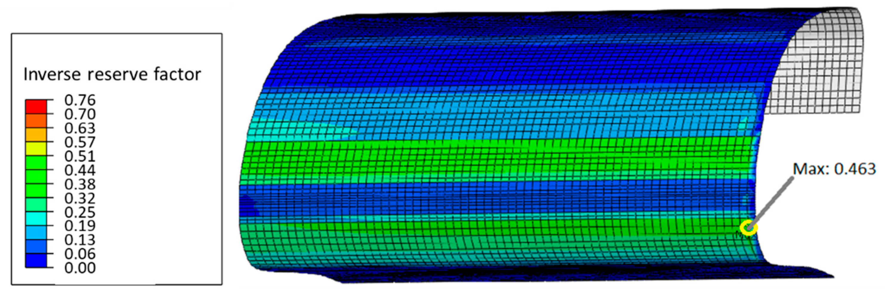
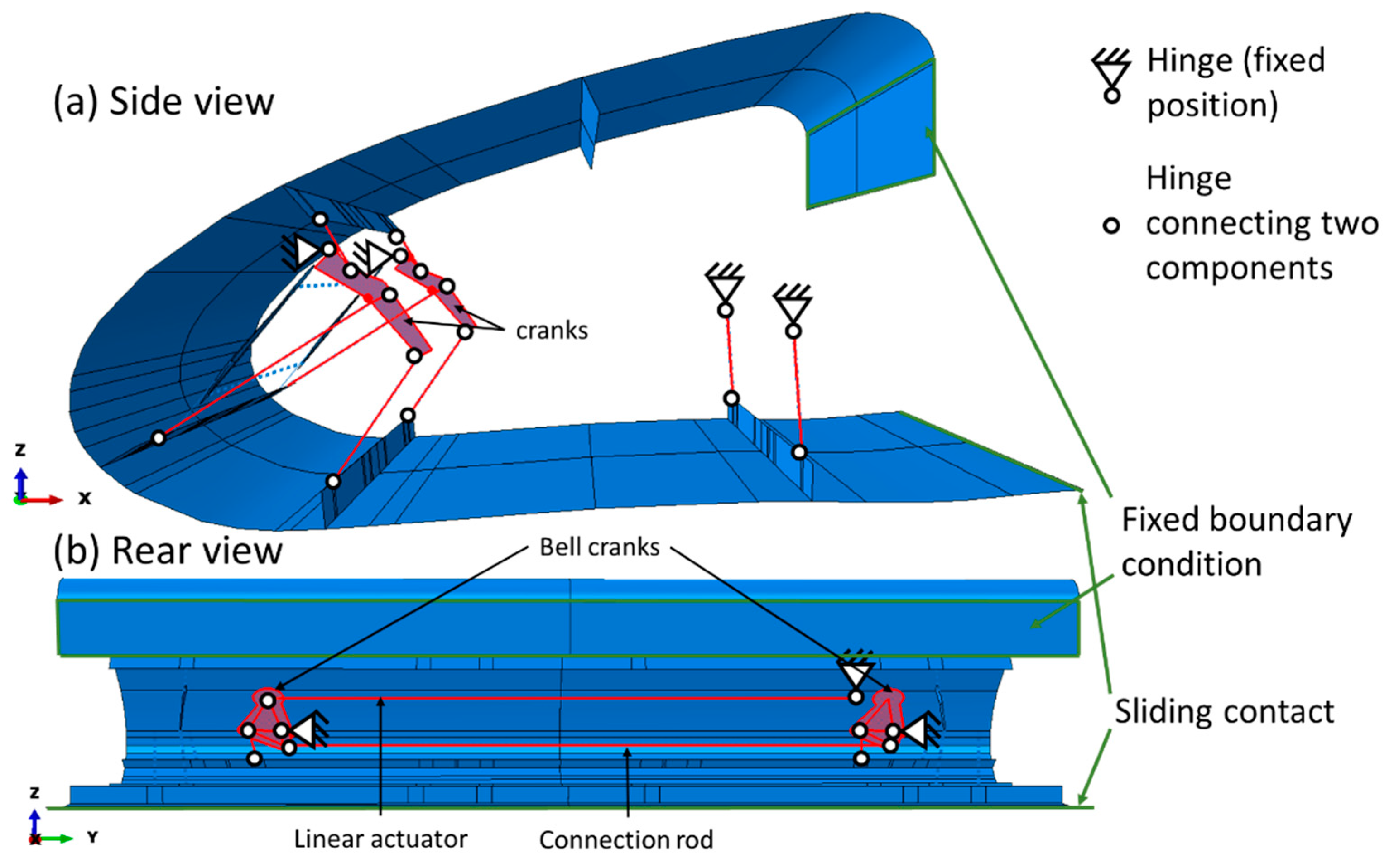
4.2. Finite Element Modeling of the Actuation System

The mechanical behaviour of the morphing leading edge system was analysed using an FE model. It includes the flexible composite structure of the skin as well as all moving parts of the kinematic system, which were modelled using kinematic constraints. It also includes the sliding contact which closes the gap at the bottom of the MLE (see Section 6). The FE model is depicted in Figure 15. It represents a MLE section of 1.3 m span.
In Figure 15a, all components of the drive mechanism are highlighted in red, which move in the x-z-plane. In Figure 15b, those components of the drive mechanism are highlighted in red, which move in the plane of the bell crank and the linear actuator. The hinges with a fixed position are supposed to be connected to the support structure. All parts of the drive mechanism are modeled as rigid parts, whereas skin and stringers are deformable with the local material properties and ply stack sequence assigned. The actuator is represented by a “translator” feature, changing its length in order to move the MLE into the desired position. This movement drives the bell crank on the left hand side of Figure 15b. A connection rod between the two bell cranks makes them move synchronously. The sliding contact at the rear bottom end of the leading edge was modeled using frictionless perpendicular behaviour. Abaqus was used as FE software for this model. Skin and stringers were discretised using quadratic quadrilateral shell elements (S8). The bending stiffness of the shell elements representing the stringers are set equal to the bending stiffness of the stringer profiles described in Section 3.2. This allows us to model the behaviour of the stringers without modeling details of their geometry. Stringers and skin are modelled as one part in the FE model. This part has been meshed with an average element size of 10 mm × 10 mm. In total, the mesh contains 22,976 Elements and 66,320 nodes. A static general procedure was used with an implicit solver, considering geometric nonlinearity.
In this FE model, the aerodynamic pressure loads for different flight conditions, which have been computed via CFD analyses (see Section 2.4), are applied to the skin surface. In Table 4, these different load conditions are listed.
  • The initial condition “0” corresponds to the unloaded MLE in the stress-free manufacturing shape, which is depicted in Figure 15.
  • Step no. 1 corresponds to the installation of the MLE to the wing. While installing the MLE, the sliding surface for the gap closure is prestressed by pushing it up against the bottom wing contour (see Section 6). For all subsequent steps, the rear bottom edge of the MLE slides on this contour. The prestressing of this sliding contact is maintained for all subsequent steps.
  • Steps no. 2 and 3 correspond to a test of the MLE on the ground without pressure loads. In step no. 2, the MLE is deformed into cruise aerofoil S4 without pressure loads.
  • In step no. 3, the MLE is deformed into the position for take-off and landing S5, still without pressure loads.
  • In step no. 4, pressure loads are applied assuming that now the plane takes off with MLE remaining in position S5 (Case S5 I in Table 3). As shown in the results of CFD analyses (Section 2.4), the highest pressure loads at the MLE occur for the flight conditions with retracted flap. This may partly be due to the fact that a higher AoA is allowed with retracted flaps. In Section 2.4, it is also shown that the highest pressure loads at the MLE occur at the highest allowed AoA. Hence, the flight condition with the highest AoA, the highest true air speed at that AoA and with retracted flaps is used as the most critical case in position S5.
  • In step no. 5, the MLE is morphed to position S4, whereas the air speed and the AoA remain constant (Case S4 I in Table 3). The results shown in Table 3 show that the pressure load on the MLE is even higher for S4 than for S5 in that flight condition. Even though it is not intended to use aerofoil S4 at high AoA, this flight condition is included into the load cycle, because it is the most critical one. Not dimensioning for it would mean adding constraints to the acceptable flight envelope depending on the MLE position.
  • Case S5 IV (aerofoil S5 with low AoA and high true air speed) in Table 3 is not considered as a critical load case. The computed suction peak value is the highest one, but it occurs at the bottom, whereas the highest suction for all other cases occurs on the upper surface of the MLE. Suction at the bottom for aerofoil S5 reduces forces on the actuation system because the aerodynamic pressure loads act in the same direction as the deformation enforced by the actuation system.
  • In step no. 6, aerofoil S4 is maintained, but the pressure loads are modified in order to correspond to cruise condition with reduced AoA and increased air speed.
  • A load cycle corresponding to one flight consists of steps no. 1 to 6 and then repeating the load conditions 5, 4, and 3 in reversed order.
For each of the last three steps, a pressure distribution was derived by CFD analyses presented in Section 2.4. In between the load cases, pressure loads have been interpolated linearly over time. Between each load case, the linear actuator moves with constant piston velocity from one position to the next one. Hence, its stroke has also been interpolated linearly over time.
The approximation of the target shapes is achieved with the proposed actuation system as computed with the FE model shown in Figure 16. While the actuation system positions the stringers exactly at the desired positions, the desired curvature of the aerofoil contour in between the stringers can only be met approximately by tailoring the local stiffness properties of the skin. The effect of the remaining deviation on aerodynamic performance is assessed using 2D CFD analysis. The results are depicted in Figure 17.
For aerofoil S5 in high lift configuration, the lift coefficient of the achieved approximation is 0.2–0.8% higher than the lift coefficient of the target aerofoil, whereas the difference in drag is in the range between −1% and +0.4%. For aerofoil S4, the comparison is made for the clean wing configuration (flaps retracted), because it is intended for flight in cruise condition. Here, larger relative deviations occur. For angles of attack between 0° and 6°, which is typically the case for cruise condition, the drag coefficient is up to 1.3% lower than the drag coefficient of the target aerofoil, whereas the deviation in lift is in between −0.3% and +1.1% in this interval. At other angles of attack, the relative deviation is higher, but regarding typical flight cycles, these conditions are of minor relevance.
The main purpose of the described FE model is the computation of the loads acting on the components of the actuation system. The loads have been computed for all hinges shown in Figure 15. As an example, for the computed loads, the required actuation forces for the different load conditions are depicted in Figure 18.
In this figure, it is shown that the highest actuation force (5.8 kN) is required in step 4 (S5 with pressure loads), even though the major part of the actuation force is due to the stiffness of the MLE (5.2 kN in step 3: S5 without pressure loads) and not to the pressure loads. The required power of the actuator depends linearly on the desired actuation speed. Hence, the choice of the velocity requirement has a major impact on the weight of the actuator. The transition between high lift and clean wing configuration is typically a slow movement that may take several seconds. The actuation stroke for morphing from aerofoil S5 to S4 is 110 mm. Assuming an actuation speed of 22 mm/s (corresponding to a deployment time of 5 s) and an actuator efficiency of 90% the required power of the electromechanical actuator is 142 W (without power reserve) for the MLE section of 1.3 m. The load cycles of all kinematic components have been computed by this FE model, and the components have been dimensioned accordingly.

5. Fatigue Tests

The material selected for the MLE must withstand the bending stresses and deformations during operation. A 4-point bending test was chosen to validate the material, since the skin of the MLE is mainly subjected to bending. The 4-point bending test was preferred over the 3-point bending test because a greater portion of the specimen is subjected to the maximum bending stresses this way. The most severe IRF according to Puck’s failure criterion [30] occurring in the MLE was determined via a FE model similar to the one described in Section 4. The displacement of the upper supports necessary to reproduce this IRF in the fatigue test was then determined via FEA of the specimens including test setup. The number of load cycles was set to 102,000, corresponding to approx. 56,000 flights.
The bending amplitude used in the 4-point bending tests corresponds to deformation from S4 to S5. However, due to the test setup, a pulsating load was realised, which is conservative in comparison to the alternating loads in the MLE. The IRF reached in these bending tests are 70% higher than the ones expected for deformation from the intermediate baseline shape into either S4 or S5 so that a sufficient safety margin is provided.
Specimens were manufactured from plates measuring 50 cm × 50 cm, which were laminated by hand lay-up using HexPly® IM7/8552 prepreg material by Hexcel®, see Figure 19.
After hand lay-up, the plates were cured in a hot press reaching a nominal thickness of about 1 mm. The coupon specimens were then cut from the plates using an abrasive water-jet cutter. The dimensions of the specimens are shown in Figure 20.
To perform the 4-point-bending fatigue tests with constant amplitudes, two different setups were used. The test setups differ in the distance between the lower supports, see Figure 21 and Figure 22 to realise two different load cases, which generate slightly different IRFs in the specimen.
All tests were generally performed with 1 Hz test frequency.
The aim of the studies was to demonstrate that the samples survive the respective bending load at least 102,000 times.
For test scenario 1, six specimens were tested up to the load cycle limit. The maximum downward displacement of the upper supports was 54 mm. In Figure 23, the test set up is shown at maximum displacement.
For test scenario 2, another six specimens were tested up to the load cycle limit. The maximum downward displacement of the upper supports was 52 mm (and thus 2 mm less than in scenario 1 because the distance between the supports is also different, see Figure 20 and Figure 21).
In summary, a service life of 102,000 cycles was demonstrated for both scenarios.

6. Gap Closure

The three most prominent configurations of the MLE are shown in Figure 24. After assembly of the skin and actuation system and mounting on the front spar of the wing, the MLE is in the intermediate baseline shape shown in grey. For cruise flight, the skin is tilted upwards by the actuation system to assume the contour shown in blue (S4). For take-off and landing, the skin is tilted downward into the high-lift configuration shown in orange (S5).
The deformation from the cruise- to the high-lift configuration not only increases the wing profile’s camber, but also its chord-length. Thus, and as mentioned in Section 3.1, the contour of the high-lift configuration is significantly longer than that of the cruise configuration. To avoid excessive membrane strains in the skin, the lower edge of the leading-edge skin is allowed to move forward and aft. The formation of a gap between it and the front spar, however, needs to be avoided to prevent the ingress of dirt and foreign objects, and also because the airflow interacting with it could cause significant noise emission. Therefore, the CFRP-skin is extended aft to overlap the lower surface of the front spar (and the parts of the wing-skin attached to it in this region). The laminate lay-up and shape of the extension are shape- and stiffness-tailored so that installation of the skin on the front spar results in a bending deformation and thus a tensioning of the overlapping part against the contact surface. To reduce wear, a thin profile running in the span-wise direction and made of an appropriate low friction material is attached to the overlapping part of the skin. When the MLE transitions from one shape to another, this slides along the lower surface of the front spar.
At this point, the exact amount of pre-tension necessary to avoid the loss of contact between the skin-extension and the front spar in all situations, e.g., also in the presence of local turbulence, has not yet been analysed in detail. For the cruise and high-lift conditions investigated so far, Figure 25 shows the contact force per metre span at the sliding contact for the load cases given in Table 4 computed with the FE model described in Section 4.2.
This figure shows that the aerodynamic pressure distribution does not cause opening of the contact. As shown in Table 4, the load cases 4, 5, and 6 are with different pressure fields, whereas the load cases 1, 2, and 3 represent cases without aerodynamic loads. The pre-tension reached with the current design is therefore sufficient. Whether this holds true for all possible flight conditions—e.g., also for negative angles of attack, which might cause suction on the wing’s lower surface—needs to be investigated in the future.
The local bending deformation necessary to achieve the pretension does not cause undue stresses in the material, as shown in Figure 26 and Figure 27.

7. Mountability Concept

7.1. System Boundaries

For the development of a mounting concept of the morphing leading edge, certain system boundaries need to be taken into account. One important requirement is the consideration of the cable routes which are attached to the front spar. Certain repositioning of the cable routes can be considered, but in general, the best accessible areas for a joint between MLE assembly and the front spar are in the top and bottom regions of the front spar. Furthermore, the inaccessible areas for mounting the MLE need to be taken into account, see Figure 28. The backside of the front spar is not accessible due to the tank positioned in this area. The sides of the MLE are not accessible due to the neighbouring systems. As a conclusion, the assembly between skin structure and actuation system, which requires accessibility from the sides, are best realised in a preassembly stage before mounting to the front spar. The preassembled system can then be attached as a single item.

7.2. Mounting Concept

After the review of the system boundaries, it is clear that the MLE is best realized as a preassembly, which is then attached to the front spar in one piece. The areas most easily accessible are at the top and bottom of the front spar. Therefore, the interfaces between MLE and front spar are best positioned there, see Figure 29. Apart from accessibility, the proposed design with its two-point support offers advantages, such as reduction of force and moment reaction in the joint compared to a single-point support, as well as sufficient space for cable routes between the two joints.
In order to attach the MLE, joining elements attached to the front spar at the top and bottom are necessary, see Figure 30. These are best positioned in those areas, where ribs on the backside support the front spar and therefore sufficient stiffness for load introduction into the front spar is provided. Structural analyses based on estimated loads show that eight M8 bolts are sufficient to transmit the loads safely.
After full preassembly, the complete MLE can be positioned on the front spar. A cut-out area in the skin on the top and bottom side allows access to the interfaces, see Figure 31. Once they are tightened, the bolts sit below the level of the skin surface. This prevents interference with the sliding movement of the skin extension (see Section 6) on the bottom surface. The cut-out area can then be covered by a lid construction.

8. Bird Strike

Keeping an eye on potential future certification of a morphing leading edge concept, one aspect to consider is the proof of bird strike resistance [36]. In particular, it must be shown that the bird does not damage the front spar of the wing and the fuel tank, as this might result in catastrophic failure of the fuel system and subsequent loss of the aircraft [37,38,39]. For this work, the proof of the bird strike resistance of the morphing leading edge was demonstrated by means of simulation. For this purpose, simulations of a bird (mass 2 kg) impacting the MLE at a velocity of 180 m/s were conducted using the explicit finite element software LS-DYNA. A summary of the simulation approach and results is given below. For further details, the reader is referred to [40].
Following the industry standard, the bird was represented by a cylinder with two semi-spherical caps and modelled using smooth particle hydrodynamics. The bird model had previously been validated against experimental data [41]. The composite skin was modelled following the established approach from [42], considering strength-based failure criteria and non-linear shear. The internal architecture of the MLE (actuators, etc.) was simplified. The simulation results clearly indicate that the relatively thin composite skin is not capable of stopping the bird from penetrating into the wing. For some impact locations, the internal architecture is capable of stopping the bird before impacting the front spar. However, for the majority of cases, the bird was sliced by the internal architecture, and large portions of the bird subsequently impacted the front spar. Therefore, a bird strike protection concept had to be sought. Following recommendations from the literature [27,42], a bird splitter/deflector concept was integrated into the FE model consisting of thin aluminium plates. The simulation results indicated that a thickness of 2.5 mm was sufficient to prevent the bird from impacting the front spar. Figure 32 shows a typical simulation result for the case including a bird strike protection shield. For illustrative purposes, the skin has been hidden in order to increase the visibility of the interaction of the bird with the internal structure.

9. Conclusions

The morphing leading edge is an appropriate solution for increasing maximum lift and stall angle of an aircraft. In contrast to classical high lift devices like Krueger flaps, the MLE avoids adding sources of turbulence on the upper wing surface. Additionally, it avoids gaps, which are typically sources of noise radiation.
Because of high aerodynamic pressure loads on the leading edge, a structure is required, which is both stiff and deformable. These conflicting requirements are addressed by a CFRP composite structure with a ply stacking sequence optimised for bending, local stiffness variation by tailoring of the composite (Section 3), and a pre-stressed sliding contact (Section 6) at the bottom of the wing. Additionally, using an intermediate baseline shape as initial geometry reduces the required strainability of the material. Cyclic material tests and numerical analysis show that the proposed skin structure is able to withstand the occurring strains for a full service life of an aircraft.
The proposed stringer design and positioning combine a high stringer stiffness in the spanwise direction with a minimised impact on deformation of the skin in the peripheral direction. Furthermore, the material composition of the stringers reduces thermal stresses, as explained in Section 3.2.
The designed actuation system for the MLE fits completely inside the leading-edge, leaving space for other systems and components like cables und tubes, which are typically located in that region of a wing. The required actuation forces allow for an electromechanical actuation of the MLE system. Together with the proposed mounting concept, which does not require any ingress from difficult to access areas behind or at the sides of the leading edge, the MLE system is designed for minimizing the impact on the aircraft design in order to allow integration in future versions of existing aircraft types.
As bird strike is an important issue for the leading edges of any aircraft wing, a protection solution against bird strike has been developed. Numerical simulations show its ability to stop birds from hitting the front spar of the wing.
Beyond the design progress presented in this paper, further work on design and qualification of the MLE system needs to be done, before such a system can be used in commercial flight operations. This includes lightweight optimization of the system, exhaustive analysis of functional and structural safety aspects, prototype testing, and certification. Furthermore, a feasible ice-protection system has to be integrated into the skin structure. A possible solution for such a system in a morphing CFRP structure is described in [6]. Further improvement of aerodynamic performance for morphing systems may be achieved using an integrated aerodynamic optimisation approach, which considers material limitations like the one reported in [43] together with structural optimisation algorithms, e.g., [44].

Author Contributions

Following the individual contribution of the authors is provided: Conceptualization, C.C.A., V.L., and D.L. Methodology, V.L., D.L., and J.-D.W. Formal analysis, S.A. and M.M. Investigation, C.C.A. and V.L. Writing—original draft preparation, C.C.A. V.L., D.L., S.A., M.M., J.-D.W., and J.D. Writing—review and editing, C.C.A., V.L., D.L., and M.M. Visualization, C.C.A. and V.L. Supervision, C.C.A. Project administration, C.C.A. and M.M. All authors have read and agreed to the published version of the manuscript.

Funding

This research was funded by the EC in the frame of JTI Clean Sky 2, grant number CS2-AlR-GAM-2016-2017 and CS2-AlR-GAM-2018-2019.

Institutional Review Board Statement

Not applicable.

Informed Consent Statement

Not applicable.

Data Availability Statement

Restrictions apply to the availability of these data. Data was partly obtained from Airbus Defence & Space and are available from the authors with the permission of Airbus Defence & Space.

Acknowledgments

The task performed by Fraunhofer was supported by the EC in the frame of JTI Clean Sky 2, which is gratefully acknowledged. We would also like to thank Airbus Defence & Space for the good cooperation within this project.

Conflicts of Interest

The authors declare no conflict of interest.

References

  1. Karakalas, A.A.; Lagoudas, D.C. Preliminary Design and Preliminary Design and Numerical Investigation of SMA Torsion Tubes for the Actuation of Articulated Adaptive Panels. ARC 2021. [Google Scholar] [CrossRef]
  2. Machairas, T.; Solomou, A.; Saravanos, D. A morphing chevron actuated by shape memory alloy wires for noise reduction. In Proceedings of the Greener Aviation: Clean Sky Breakthroughs and Worldwide Status, Brussels, Belgium, 12–14 March 2014. [Google Scholar]
  3. ACARE Advisory Council for Aviation Research and Innovation in Europa. FlightPath2050 Goals. Available online: https://www.acare4europe.org/sria/flightpath-2050-goals/protecting-environment-and-energy-supply-0 (accessed on 20 January 2021).
  4. Sinapius, M.; Monner, H.P.; Kintscher, M.; Riemenschneider, J. DLR’s Morphing Wing Activities within the European Network. In Mechanics for the World, Procedia IUTAM 10 (2014), Proceedings of the 23rd International Congress of Theoretical and Applied Mechanics, Beijing, China, 9–24 August 2012; ICTAM2012, S. 416–426; Elsevier: Amsterdam, The Netherlands, 2014. [Google Scholar] [CrossRef] [Green Version]
  5. Morishima, R. Analysis of Composite Wing Structures with A Morphing Leading Edge. Ph.D. Thesis, Cranfield University, Bedford, UK, 2011. Available online: http://dspace.lib.cranfield.ac.uk/handle/1826/6797 (accessed on 16 March 2021).
  6. Monner, H.P.; Kintscher, M.; Lorkowski, T.; Storm, S. Design of a Smart Droop Nose as Leading Edge High-Lift System for Transportation Aircrafts. In Proceedings of the 50th AIAA/ASME/ASCE/AHS/ASC Structures, Structural Dynamics, and Materials Conference, Palm Springs, CA, USA, 4–7 May 2009. Article ID AIAA 2009-2128. [Google Scholar] [CrossRef]
  7. Colletti, C.R.; Ansell, P.J. Design of an Airfoil Morphing Leading Edge for High-Lift Applications using a Genetic Algorithm. In Proceedings of the AIAA SciTech 2021 Forum, Nashville, TN, USA, 1–15 & 19–21 January 2021. [Google Scholar] [CrossRef]
  8. Ameduri, S. Morphing of the Leading Edge. In Morphing Wing Technologies; Butterworth-Heimann: Oxford, UK, 2018; pp. 491–515. [Google Scholar] [CrossRef]
  9. Communier, D.; Le Besnerais, F.; Botez, R.M.; Wong, T. Design, Manufacturing and testing of a New Concept for a Morphing Leading Edge using a Subsonic Blow Down Wind Tunnel. Biomimetics 2019, 4, 76. [Google Scholar] [CrossRef] [PubMed] [Green Version]
  10. Kintscher, M.; Monner, H.P.; Heintze, O. Experimental Testing of a Smart Leading Edge High Lift Device For Commerical Transportation Aircrafts. In Proceedings of the 27th International Congress on the Aeronautical Sciences, Nice, France, 19–24 September 2010; ISBN 978-0-9565333-0-2. [Google Scholar]
  11. Peel, L.D.; Meija, J.; Narvaez, B.; Thompson, K.; Lingala, M. Development of a Simple Morphing Wing using Elastomeric Composite Skins and Actuators. In Proceedings of the SMASIS08—ASME Conference on Smart Materials, Adaptive Structures and Intelligent Systems, Ellicott City, MD, USA, 28–30 October 2008. [Google Scholar] [CrossRef]
  12. Geier, S.; Kintscher, M.; Mahrholz, T.; Wierach, P.; Monner, H.-P.; Wiedemann, M. Characterization of multi-functoinal skin-material for morphing leading-edge applications. In Active and Passive Smart Structures and Integrated Systems 2013; Active and Passive Smart Structures and Integrated Systems; International Society for Optics and Photonics: Washington, DC, USA, 2013; p. 868818. [Google Scholar] [CrossRef]
  13. Essa, Y.; Martin de la Escalera Cutillas, F.; Dimino, I.; Ciminello, M.; Concilio, A. Manufacturing and testing of Smart Morphing SARISTU Trailing Edge. In Smart Intelligent Aircraft Structures (SARISTU), Proceedings of the Final Project Conference, Moscow, Russia, 19–21 May 2015; Wölcken, P., Papadopoulos, M., Eds.; Springer International Publishing: Berlin/Heidelberg, Germany, 2015; pp. 199–215. [Google Scholar] [CrossRef]
  14. Wildscheck, A.; Storm, S.; Herring, M.; Drezga, D.; Korian, V.; Roock, O. Design, Optimization, testing, verification, and Validation of the Wingtip Active Trailing Edge. In Smart Intelligent Aircraft Structures (SARISTU), Proceedings of the Final Project Conference, Moscow, Russia, 19–21 May 2015; Wölcken, P., Papadopoulos, M., Eds.; Springer International Publishing: Berlin/Heidelberg, Germany, 2015; pp. 219–255. [Google Scholar] [CrossRef]
  15. Drezga, D.; Korian, V.; Roock, O.; Lopez, B.; Fiedler, A.; Storm, S.; Snop, V. Winglet Design, Manufacturing, and Testing. In Smart Intelligent Aircraft Structures (SARISTU), Proceedings of the Final Project Conference, Moscow, Russia, 19–21 May 2015; Wölcken, P., Papadopoulos, M., Eds.; Springer International Publishing: Berlin/Heidelberg, Germany, 2015; pp. 257–273. [Google Scholar] [CrossRef]
  16. Heintze, O.; Steeger, S.; Falken, A.; Heckmann, J. Enhanced Adaptive Droops Nose—from Computer Model to Multi-functional Integrated Part. In Smart Intelligent Aircraft Structures (SARISTU), Proceedings of the Final Project Conference, Moscow, Russia, 19–21 May 2015; Wölcken, P., Papadopoulos, M., Eds.; Springer International Publishing: Berlin/Heidelberg, Germany, 2015; pp. 97–111. [Google Scholar] [CrossRef]
  17. Kintscher, M.; Kirn, J.; Storm, S.; Peter, F. Assessment of the SARISTU Enhanced Adaptive Droop Nose. In Smart Intelligent Aircraft Structures (SARISTU), Proceedings of the Final Project Conference, Moscow, Russia, 19–21 May 2015; Wölcken, P., Papadopoulos, M., Eds.; Springer International Publishing: Berlin/Heidelberg, Germany, 2015; pp. 113–140. [Google Scholar] [CrossRef] [Green Version]
  18. Evenblij, R.; Kong, F.; Koimtzuglou, C.; Ciminello, M.; Dimino, I.; Concilio, A. A Shape Sensing for Morphing Structures Using Fiber Bragg Grating Technology. In Smart Intelligent Aircraft Structures (SARISTU), Proceedings of the Final Project Conference; Wölcken, P., Papadopoulos, M., Eds.; Springer International Publishing: Berlin/Heidelberg, Germany, 2015; pp. 471–491. [Google Scholar] [CrossRef]
  19. Ma, Z.; Chen, X. Fiber Bragg Grating Sensors for Aircraft Wing Measurement: Recent Applications and Technical Analysis. Sensors 2018, 19, 55. [Google Scholar] [CrossRef] [PubMed] [Green Version]
  20. Święch, Ł. Calibration of a Load Measurement System for an Unmanned Aircraft Composite Wing Based on Fibre Bragg Gratings and Electrical Strain Gauges. Aerospace 2020, 7, 27. [Google Scholar] [CrossRef] [Green Version]
  21. Airoldi, A.; Sala, G.; Evenblij, R.; Koimtzoglou, C.; Loutas, T.; Carossa, G.M.; Mastromauro, P.; Kanakis, T. Load Monitoring by Means of Optical Fibres and Strain Gages. In Smart Intelligent Aircraft Structures (SARISTU), Proceedings of the Final Project Conference, Moscow, Russia, 19–21 May 2015; Wölcken, P., Papadopoulos, M., Eds.; Springer International Publishing: Berlin/Heidelberg, Germany, 2015; pp. 433–469. [Google Scholar] [CrossRef]
  22. Sodja, J.; Martinez, M.J.; Simpson, J.C.; De Breuker, R. Experimental evaluation of a morphing leading edge concept. J. Intell. Mater. Syst. Struct. 2019, 30, 2953–2969. [Google Scholar] [CrossRef] [Green Version]
  23. Vasista, S.; Riemenschneider, J.; Keimer, R.; Monner, H.P.; Nolte, F.; Horst, P. Morphing Wing Droop Nose with Large Deformation: Ground Tests and Lessons Learned. Aerospace 2019, 6, 111. [Google Scholar] [CrossRef] [Green Version]
  24. Ameduri, S. A SMA based Morphing Leading edge Architecture. Adv. Mater. Res. 2014, 1016, 383–388. [Google Scholar] [CrossRef]
  25. Contell Asins, C.; Landersheim, V.; Schwarzhaupt, O. Development, manufacturing and testing of a 1:1 smart morphing leading edge demonstrator. In Proceedings of the Greener Aviation 2016, Brussels, Belgium, 11–13 October 2016. paper ID 137. [Google Scholar]
  26. Thuwis, G.A.A.; Abdalla, M.; Gürdal, Z. Optimization of a variable-stiffness skin for morphing high-lift devices. Smart Mater. Struct. 2010, 19, 124010. [Google Scholar] [CrossRef]
  27. De Gaspari, A.; Cavalieri, A.; Ricci, S. Advanced Design of a Full-Scale Active Morphing Droop Nose. Int. J. Aerosp. Eng. 2020. [Google Scholar] [CrossRef]
  28. Contell Asins, C.; Landersheim, V.; Wacker, J.-D.; Adachi, S.; Arnold-Keifer, S.; May, M. Design of a Morphing Leading Edge for Use as a High Lift Device for A Regional Aircraft. IOP Conf. Ser. Mater. Sci. Eng. 2021, 1024, 012033. [Google Scholar] [CrossRef]
  29. Menter, F.R. Two-equation eddy-viscosity turbulence models for engineering applications. AIAA J. 1994, 32, 1598–1605. [Google Scholar] [CrossRef] [Green Version]
  30. Puck, A. Festigkeitsanalyse von Faser-Matrix-Laminaten—Modelle für die Praxis; Carl Hanser Verlag: München, Germany; Wien, Austria, 1996. [Google Scholar]
  31. Barbarino, S.; Saavedra Flores, E.I.; Ajaj, R.M.; Dayyani, I.; Friswell, M.I. A review on shape memory alloys with applications to morphing aircraft. Smart Mater. Struct. 2014, 23, 063001. [Google Scholar] [CrossRef]
  32. Henry, A.C.; Molinari, G.; Rivas-Padilla, J.R.; Arrieta, A.F. Smart Morphing Wing: Optimization of Distributed Piezoelectric Actuation. AIAA J. 2019, 56. [Google Scholar] [CrossRef]
  33. Mazzoleni, M.; Maccarana, Y.; Previdi, F.; Pispola, G.; Nardi, M.; Perni, F.; Toro, S. Development of a reliable electro-mechanical actuator for primary control surfaces in small aircrafts. In Proceedings of the 2017 IEEE International Conference on Advanced Intelligent Mechatronics (AIM), Munich, Germany, 3–7 July 2017. [Google Scholar] [CrossRef]
  34. Wheeler, P.; Bozhko, S. The More Electric Aircraft: Technology and challenges. IEEE Electrif. Mag. 2014, 2, 6–12. [Google Scholar] [CrossRef]
  35. Marlett, K. Hexcel 8552 IM7 Unidirectional Prepreg 190 gsm & 35%RC Qualification Material Data Report. NCAMP Test Report Number: CAM RP-2009-015 Rev A, 22 April 2011. Available online: https://www.niar.wichita.edu/coe/ncamp_documents/Hexcel%208552/CAM-RP-2009-015%20Rev%20A%20April%2022%202011%20Hexcel%208552%20IM7%20Uni%20Data%20Report.pdf (accessed on 16 March 2021).
  36. European Union Aviation Safety Agency (EASA). Certification Specification and Acceptable Means of Compliance for Large Aeroplanes CS-25, Amendment 25; European Union Aviation Safety Agency (EASA): Cologne, Germany, 2020. [Google Scholar]
  37. Heimbs, S.; Nogueira, A.; Hombergsmeier, E.; May, M.; Wolfrum, J. Failure behavior of composite T-joints with novel metallic arrow-pin reinforcements. Compos. Struct. 2014, 110, 16–28. [Google Scholar] [CrossRef]
  38. May, M.; Ganzenmüller, G.C.; Wolfrum, J.; Heimbs, S. Analysis of composite T-joint designs for enhanced resistance to hydrodynamic ram. Compos. Struct. 2015, 125, 188–194. [Google Scholar] [CrossRef]
  39. May, M.; Arnold-Keifer, S.; Landersheim, V.; Laveuve, D.; Contell Asins, C.; Imbert, M. Bird Strike Resistance of a CFRP Morphing Leading Edge. Compos Part C 2021. [Google Scholar] [CrossRef]
  40. May, M.; Haase, T.; Leost, Y.; Wegmann, M.; Blacha, M. Bird strike analyses of RACER fast rotorcraft. In Proceedings of the AIAA 2019 SciTech Forum, San Diego, CA, USA, 7–11 January 2019. [Google Scholar] [CrossRef]
  41. May, M.; Arnold-Keifer, S.; Haase, T. Damage resistance of composite structures with unsymmetrical stacking sequence subjected to high velocity bird impact. Compos. Part. C 2020, 1. [Google Scholar] [CrossRef]
  42. Chary, C. Development and Validation of a Bird Strike Protection System for an Enhanced Adaptive Droop Nose. In Smart Intelligent Aircraft Structures (SARISTU), Proceedings of the Final Project Conference; Wölcken, P., Papadopoulos, M., Eds.; Springer International Publishing: Berlin/Heidelberg, Germany, 2015; pp. 71–83. [Google Scholar] [CrossRef]
  43. Magrini, A.; Benini, E.; Ponza, R.; Wang, C.; Khodaparast, H.H.; Friswell, M.I.; Landersheim, V.; Laveuve, D.; Contell Asins, C. Comparison of Constrained Parameterisation Strategies for Aerodynamic Optimisation of Morphing Leading Edge Airfoil. Aerospace 2019, 6, 31. [Google Scholar] [CrossRef] [Green Version]
  44. Wang, C.; Khodaparast, H.H.; Friswell, M.I.; Magrini, A.; Ponza, R.; Benini, E.; Landersheim, V.; Laveuve, D.; Contell Asins, C. Conceptual-level Evaluation of a Variable Stiffness Skin for a Morphing Wing Leading Edge. J. Aerosp. Eng. 2019, 233, 5703–5716. [Google Scholar] [CrossRef] [Green Version]
Figure 1. Fraunhofer morphing leading edge demonstrator in the climate wind tunnel.
Applsci 11 02752 g001
Figure 2. LE (leading edge) comparison of profiles S4HL, BLHL, 050HL, and S5HL [28].
Applsci 11 02752 g002
Figure 3. 3D mesh generated around profile S5HL. (a) CFD mesh including far field. (b) Detail view of CFD mesh around the wing. (c) Channel between the wing main part and the flap.
Applsci 11 02752 g003
Figure 4. Calculated lift (a) and drag (b) coefficients for high-lift profiles.
Applsci 11 02752 g004
Figure 5. Pressure and flow (left) and cp distribution (right) for cruise profile S5 in four extreme conditions.
Applsci 11 02752 g005
Figure 6. Pressure and flow (left) and cp distribution (right) for high-lift profile S5HL in three extreme conditions.
Applsci 11 02752 g006
Figure 7. Simplified flow-chart of the process resulting in definition of the skin laminate.
Applsci 11 02752 g007
Figure 8. Curvature analysis for placement of stringers (schematic); (a) abscissa: Location along the MLE-contour; blue: Curvature along contour S4, red: Curvature along contour S5, grey: Difference between S4 and S5 curvatures, grey squares: Selected locations for stringers 2 to 5 (region of stringer 1 does not change curvature very much anyhow); (b) Blue curve is S4, red curve is S5 (not to scale).
Applsci 11 02752 g008
Figure 9. Stringers formed from the inner part of the skin; the final decision on specific fillet material has not been made yet.
Applsci 11 02752 g009
Figure 10. Inverse reserve factors due to thermal residual stresses in the undeformed skin for cooling to −45 °C; (a) ABAQUS-model (linear shell elements) of the CRFP-only stringers largely shows inverse reserve factor (IRF)-values (even without morphing) of ca. 0.35 (green) and above; (b) ANSYS-model (linear shell elements—here displayed with their specified thickness) shows IRF-values mostly around 0.1 and below (also without morphing); upper right corner: Design principle of the stringer-reinforcement assumed for the ANSYS-model (this has since been superseded by the design shown in Figure 11).
Applsci 11 02752 g010
Figure 11. Steel profiles for additional stiffening of the stringers; stringers 1, 2, 4, and 5 are reinforced by a pair of C-section profiles, each, while higher loads at stringer 3 require box-section profiles; cylindrical parts are fittings for the kinematic system; stringer 1 is not connected to the kinematic system and therefore does not possess fittings; the CFRP-portion of each stringers (not shown here) is sandwiched between the two profiles.
Applsci 11 02752 g011
Figure 12. Kinematic system design of the morphing leading edge [28].
Applsci 11 02752 g012
Figure 13. Derived intermediate baseline together with target shapes S4 and S5.
Applsci 11 02752 g013
Figure 14. Distribution of inverse reserve factor in the skin of the morphing leading edge.
Applsci 11 02752 g014
Figure 15. FE (finite element) model of the morphing leading edge (MLE) system shown from two different perspectives: (a) side view, (b) rear view.
Applsci 11 02752 g015
Figure 16. Achieved approximation of target shapes computed by FE model for load cases 4 and 5.
Applsci 11 02752 g016
Figure 17. Effect of deviation between target aerofoil and achieved approximation on lift (a) and drag (b) coefficients.
Applsci 11 02752 g017
Figure 18. Actuation forces computed using the described FE model.
Applsci 11 02752 g018
Figure 19. Hand lay-up of the laminate; after curing in a hot-press, specimens are cut from the plate by abrasive water-jet.
Applsci 11 02752 g019
Figure 20. Specimen for four point bending tests (all dimensions in mm).
Applsci 11 02752 g020
Figure 21. Four point bending setup for test scenario 1 (all dimensions in mm).
Applsci 11 02752 g021
Figure 22. Four point bending setup for test scenario 2 (all dimensions in mm).
Applsci 11 02752 g022
Figure 23. Specimen in four point bending test setup with maximum displacement of the upper supports [28].
Applsci 11 02752 g023
Figure 24. Schematic view of cruise-configuration (S4, blue), intermediate baseline shape (grey), and high-lift configuration (S5, orange) of the MLE; CFRP-stringers are each stiffened by a pair of steel profiles with box- or C-shaped cross-sections, respectively—the figure shows their cross-section including the fittings for the kinematic system (see Figure 11 for more detail); the rearward extension of the MLE’s skin slides along the lower surface of the front spar.
Applsci 11 02752 g024
Figure 25. Contact force per meter span at the sliding contact for the load cases given in Table 4 computed with the FE model described in Section 4.2.
Applsci 11 02752 g025
Figure 26. Inverse reserve factors in the skin-extension according to Puck’s failure criterion in cruise-configuration (S4); IRFs are very low.
Applsci 11 02752 g026
Figure 27. Inverse reserve factors in the skin-extension according to Puck’s failure criterion in high-lift configuration (S5); IRFs are higher than in cruise-configuration but still acceptable.
Applsci 11 02752 g027
Figure 28. Space inaccessible for assembly.
Applsci 11 02752 g028
Figure 29. Positioning of interfaces between MLE and front spar.
Applsci 11 02752 g029
Figure 30. Joining elements for MLE attached to the front spar (left) and supporting stiffening elements on opposite side (right).
Applsci 11 02752 g030
Figure 31. Bolted joint between MLE and front spar (left), cut-out areas at top and bottom of skin element (right) [28].
Applsci 11 02752 g031
Figure 32. Bird strike simulation. Left: Impact configuration; right: Interaction of bird with internal structure.
Applsci 11 02752 g032
Table 1. List of maximum lift coefficients and stall angles.
ProfilesBLHLS4HL050HLS5HL
Max Lift Coeff. 2.802.692.913.06
Stall Angle/°14.213.215.016.4
Table 2. List of defined extreme conditions both for cruise and high-lift profiles.
ConditionsFor Cruise ProfilesFor High-Lift Profiles
IIIIIIIVI′II′III′
Air Speed/(m/s)130.6153.7192.1184.472.082.392.6
Angle of Attack/°14.49.75.21.010.06.03.1
Table 3. List of suction peak values in extreme conditions.
ProfileConditionMax Pressure Coefficient cpMax Suction (kPa)
S4I−4.53−21.2
II−2.51−16.3
III−1.21−12.3
IV−0.82−7.7
S5I−3.57−16.7
II−2.22−14.4
III−1.25−12.7
IV−2.62−24.5
S4HLI′−6.48−20.7
II′−3.79−15.8
III′−2.45−12.9
S5HLI′−4.82−15.4
II′−3.14−13.1
III′−2.24−11.8
Table 4. Load conditions (steps) analysed in FE model.
No.0123456
GeometryManu.BLS4S5S5S4S4
Angle of Attack/°000014.4114.411
True Air speed/(m/s)0000130.6130.6184.4
Publisher’s Note: MDPI stays neutral with regard to jurisdictional claims in published maps and institutional affiliations.

