Article

A Time-Shifting Algorithm for Alleviating Convergence Difficulties at Interior Acoustic Resonance Frequencies

Department of Systems Engineering and Naval Architecture, National Taiwan Ocean University, Keelung 20224, Taiwan
Appl. Sci. 2021, 11(6), 2701; https://doi.org/10.3390/app11062701
Submission received: 24 February 2021 / Revised: 14 March 2021 / Accepted: 15 March 2021 / Published: 17 March 2021
(This article belongs to the Section Acoustics and Vibrations)

Abstract

:
This paper proposes a time-shifting boundary element method in the time domain to calculate the radiating pressures of an arbitrary object pulsating at eigenfrequencies of the interior (i.e., interior resonance frequencies). In this paper, the frequency shifting is time-step-dependent and could be viewed as an iterative, or relaxation, technique for the solution of the problem. The proposed method avoids numerical problems due to the internal resonance frequency by initializing the iteration with each scaled frequency. The scaled frequency is approximately equal to the true frequency at the last iterating time step. A sphere pulsating at the eigenfrequency in an infinite acoustic domain was calculated first; the result was compared with the analytical solution, and they were in good agreement. Moreover, two arbitrary-shaped radiators were taken as study cases to predict the radiating pressures at the interior resonance frequencies, and robustly convergent results were obtained. Finally, the accuracy of the proposed method was tested using a problem with a known solution. A point source was placed inside the object to compute the surface velocities; the computed surface pressures were identical to the pressures computed using the point source.

1. Introduction

The radiating waves used for some specific purposes, such as remote sensing and military defense, are a topic worthy of research. The boundary element method (BEM) is widely used for solving problems involving radiating waves; however, incorrect results due to internal resonance frequencies constitute a problem to be solved. Therefore, this study aims to develop a BEM in the time domain to compute the radiating waves of an arbitrary pulsating object. The results show that the numerical instability at the internal resonance frequency is improved by shifting the inception of the first time step.
Non-unique solutions appear at the internal resonance frequencies for the BEM. The well-known combined Helmholtz integral equation formulation (CHIEF) introduced by Schenck [1] has been widely applied to overcome non-unique solutions at eigenfrequencies in the frequency domain. The CHIEF method collocates the Helmholtz integral equation at a few interior points inside the pulsating object. Then, the constraint equations are formed with the existing surface Helmholtz equation. Burton and Miller [2] solved the non-uniqueness problem at interior resonance frequencies by deriving a second integral equation (i.e., the hypersingular BIE) and combining it with the original boundary integral equation. However, the formulation presents serious computational drawbacks due to the presence of hypersingular integrals. According to the convolution quadrature rules, Lubich [3,4] proposed a numerical method to solve the integral equations. His method is suitable for the approximation of convolution integrals for which the kernel is singular or has components at different time scales. The boundary integral equation for an absorption–diffusion problem was calculated, and the numerical solution was re-interpreted as that of semi-discretization in the time of the original problem. Ebenezer and Stepanishen [5] solved transient radiation by the wave-vector-time domain and Kirchhoff integral equation methods. The wave-vector-time domain method is only suitable for simple objects. When using the Kirchhoff integral equation method, the error increases with forward marching time. Hwang and Chang [6] distributed the interior surface source to solve the singularity and non-unique solutions of the conventional boundary integral equation. The interior source surface is selected through an error estimate of the numerical integration. In Liu and Rizzo [7], a general form of the hypersingular BIE was developed for 3-D acoustic wave problems, containing at most weakly singular integrals. The weakly singular form of the hypersingular BIE for exterior acoustics problems is highly efficient and competitive. The convolution quadrature method shown in Lubich [8] takes into account the time dependency in spatial discretizations for linear time-invariant non-homogeneous evolution equations and is more efficient than the Galerkin or collocation time approximations. Hwang [9] regularized the hypersingular integral in the Helmholtz integral equation. The computations were carried out by the standard Gaussian quadrature procedure without any special quadrature scheme or excessive quadrature points near singular points. Liu and Chen [10] showed that the smoothness requirement is a serious issue associated with the hypersingular BIE and proposed an improved weakly singular form of the hypersingular BIE. This new form involves only tangential derivatives of the density function, and its discretization is thus easier to perform. Qian et al. [11] derived the non-hypersingular boundary integral equation for problems involved in the composite Helmholtz integral equation at the interior resonance frequency. The Burton–Miller-type integral equation was derived by Chappell et al. [12] to stabilize numerical computing at the interior resonance frequency. Kao and Kehr [13] proposed a robust iterating BEM in the time domain to solve scattered waves for an arbitrary object without considering the interior resonance frequency. Hackbusch et al. [14] employed the convolution quadrature method for discretization in time and the Galerkin boundary element method for space discretization. An a priori cut-off strategy was presented to efficiently reduce errors in numerical integration due to discretization. Michael et al. [15] included a controlling factor in the boundary integral equation for the time-domain BEM to stabilize numerical computing at the interior resonance frequency. Jang and Ih [16] suppressed low-order fictitious internal modes, which cause non-unique solutions within the effective frequency range of boundary element calculations, by the newly formulated time-domain CHIEF method. The fast multipole method, FMM-BEM, as developed by Qian et al. [17], has verified that the drawback of fully populated system matrices in BEM could be improved. Christophe and Alexandre [18] regularized the hypersingular Helmholtz integral (Burton and Miller formulation) according to the identities from the associated Laplace equation. In the scheme, weakly singular integrals are computed. The time-domain equivalent source method (TESM) was developed by Zhang et al. [19] to solve radiating waves. The TESM was formulated as a time averaging scheme to reduce instability due to errors amplified exponentially with time. Kao [20] defined a weighing factor for the time-domain BEM for a complex object, including sharp edges and indented surfaces. Kao [21] proposed a step approach method in the time domain to calculate the radiated waves from an arbitrary obstacle pulsating with multiple frequencies. However, the algorithm suffers from non-uniqueness difficulties at the interior resonance frequency, and these problems were not discussed. Bi et al. [22] built the eigenvalue system by reformulating the inverse time domain boundary element method into an iterative format. The proper ratio of truncated singular values was selected to ensure numerical stability. The referred works in the literature were all applied to the problem of radiating waves. Schenck [1], Burton and Miller [2], Hwang and Chang [6], Qian et al. [11], Chappell et al. [12], Michael et al. [15], and Ih [16] focused on overcoming non-unique solutions at the interior resonance frequency. Lubich [3,4], In Liu and Rizzo [7], Hwang [9], Liu and Chen [10], Hackbusch et al. [14], and Christophe and Alexandre [18] regularized the hypersingular integral in the Helmholtz integral equation. Ebenezer and Stepanishen [5] and Zhang et al. [19] provided new methods to reduce the error increasing with forward marching time.
In comparison to the published literature, the following improvements and innovations are made in the present method. During the approaching process, there is no error accumulation, and the numerical scheme is stabilized at the interior resonance frequency without applying any controlling factor. Because Green’s functions are combined as the retarded terms, the boundary integration can be treated easily without applying equivalent sources, a time-averaging scheme, or convolution quadrature. The iteration based on the derived formulations is robustly convergent, and it is unnecessary to filter any troublesome waves at each time step in the time domain. The radiator can be arbitrarily shaped, and the pulsating velocity on the object surface can be formed by arbitrary frequencies. Robust results are obtained by the proposed BEM.

2. An Iterating Boundary Element Method with a Relaxation Technique

2.1. Theoretical Formulations

In this paper, the vibration is taken to be sinusoidal and only at a few frequencies. Frequencies at which other methods fail (i.e., the eigenfrequencies of the interior problem) are of primary interest here. According to Kao and Kehr [13], the boundary integral equation can be derived as the following discrete forms in the time domain.
C ( H )   P r ( H , t ) =   A part ( t ) + B part ( t )
A part =   m = 1 M {   [ P r ( Q , t r / c )   ( 1 r 2 ) P r ( Q , t r / c ) t 1 c r ]   ( r . n ) } m   Δ S m 4 π
B part = Re { m = 1 M [ J = 1 i ω J ρ V J ( Q ) e i ω J ( t r c ) ]   1 r Δ S m 4 π   } = Re { m = 1 M [ J = 1 i ω J ρ V ^ J ( Q ) e i ω J t ]   1 r Δ S m 4 π   }
Here, C(H) is the solid angle for the field point, H is the field point, Q is the source point, Pr is the radiating acoustic pressure, S is the body surface with outward normal vector n, r is the distance between the field point and source point, ρ is the mean density of the fluid, VJ is the pulsating amplitude of the normal velocity, V ^ J is the complex pulsating amplitude of the normal velocity, ωJ is the angular frequency of VJ, and c is the speed of sound. The object is divided into M-many elements.
Equations (1)–(3) can work for geometries both in free space and in half space. When the half-space problem is considered, a symmetrical geometry is built to present the infinite plane of symmetry (Figure 1). As shown in Figure 1, an arbitrary object that is symmetric in the XY plane can be considered as a half-space problem. As the infinite plane of the half space is assumed to be rigid, the symmetrical geometry has positive pulsating amplitudes and radiating pressures with respect to the actual geometry (i.e., positive image). On the contrary, negative pulsating amplitudes and radiating pressures with respect to the actual geometry (i.e., negative image) are specified on the symmetrical geometry for the soft infinite plane.

2.2. The Relaxation Technique

In Kao and Kehr [13], Equations (1)–(3) are applied in solving the radiating waves. The right-hand side of Equation (1) is calculated by Equations (2) and (3). The calculated value is then used to update the left-hand side of Equation (1). However, the algorithm is expected to have numerical instability for the eigenfrequency of the interior problem (i.e., interior resonance frequency). Numerical instability also appears for the frequency-domain BEM at eigenfrequencies corresponding to an internal problem. The pulsating frequency, ωJ, appears in Equation (3), B part . In order to overcome these problems at the interior resonance frequency, B part should be reformulated in this paper.
The main concept of the proposed boundary element method is shifting the frequency by shifting the field time in every time step, in order to avoid numerical divergence due to the eigenfrequency of the interior problem. The idea process can be illustrated by Figure 2, which shows that the radiating pressure for the nth time step at time tn is Pr(tn). The time interval of each step is Δt. In this paper, each time interval is treated as a time element. For the nth time step, the time-shifted point is at time (tn + F Δt).
t n = t n + F Δ t ,   ( 0 < F < 1 )
The value of F is between 1 and 0 (i.e., 0 < F < 1). In this paper, the value of F is recommended to be a multiple of 0.35 (i.e., 0.35 or 0.7) for quick convergence. The recommended F value (0.35) was obtained by the numerical tests carried out in Section 3.1. According to the numerical test, a larger pulsating frequency needs a larger F (i.e., F = 0.7) to effectively stabilize the iterating process.
In every time step, Pr(tn) is approximated by Pr(tn + F∙Δt). In other words, the radiating pressure of the nth time step at time tn, Pr(tn), is calculated by the time-shifted point of the nth time element:
P r ( t n ) P r ( t n + F   Δ t ) , ( 0 < F < 1 ) .
The concept illustrated above was applied to the equations (Equations (1)–(3)) derived by Kao and Kehr [13], and the boundary integral equation was then discretized as Equation (6).
C ( H m )   P r ( H m , t n ) L = 1 M [ A p a r t ( t n + F   Δ t ) + B p a r t ( t n + F   Δ t ) ]   = L = 1 M [ A p a r t ( t n ) + B p a r t ( t n ) ]
The time period includes N-many time steps (n = 1~N). C(Hm) is the solid angle of the mth field point. Because the field point is located on the smooth element of the radiator in this paper, C(Hm) has the value 0.5. The time of the field point at the nth time step (tn) is presented as follows:
t n = 2 π ω J   ( n 1 ) ( N 1 ) = Δ t ( n 1 ) , ( n = 1 , 2 , , N ) .
If a larger N is selected, the iterations can continue for longer.
Because the present method is a time-domain scheme, B part in Equation (6) can be reorganized as follows:
B part ( t n + F   Δ   t ) = B part ( t n ) = m = 1 M { [ J = 1 A J ( Q ) sin ( ω J t n ω J r c ) ] 1 r   } m Δ S m 4 π = m = 1 M { [ J = 1 A J ( Q ) sin ( ω J t n ω J r c ) ] 1 r   } m Δ S m 4 π
A J ( Q ) = ω J ρ V J ( Q )
ω J = ω J t n t n = ω J ( t n + F   Δ t ) t n
where n is the time step index. Equation (10) can be reformulated as
ω J = ω J t n t n = ω J ( t n + F Δ t ) t = ω J ( 1 + F n 1 )
Equation (11) helps make clear that the frequency shifting is time-step-dependent and could be viewed as an iterative, or relaxation, technique for the solution of the problem. The method introduced in this paper avoids numerical problems due to the internal resonance frequency by initializing the iteration with each frequency scaled to ω J ( 1 + F n 1 ) . By rescaling the frequency at successive time steps, at the end of the iterating process (i.e., the last time step) the shifted frequency is
ω J = ω J ( 1 + F N 1 ) ω J
In other words, the solution frequencies are approximately equal to the true frequencies. Clearly, by taking enough time steps, N is large enough to make ω J as close as necessary to ω J , and the solution is valid.
This method works because the calculated solution coefficients change by a small amount between time steps, so that a small change in the frequency does not disturb the solution and allows for smooth convergence to the correct answer; when ω J ω J , there is only a small number of time steps required, so instability in the solution does not grow before the end of the time steps.
AJ(Q) does not change the numerical value used in the computation and will not cause numerical instability at the eigenfrequency of the interior. The term Apart in Equation (6) can also be reformulated:
A part ( t n + F   Δ t ) = A part ( t n ) = m = 1 M { [ P r ( Q , t n r / c )   ( 1 r 2 ) P r ( Q , t n r / c ) t   1 c r ] ( r . n ) } m Δ S m 4 π .
The interpolated term ( P r ( Q , t r / c ) ) and the differential term ( P r ( Q , t r / c ) t ) in Equation (13) can be evaluated by the linear finite difference method (FDM) in Burden and Faires [23]. The reason the linear FDM is used is because linear FDM is common and easy for interpolation.
Substituting Equations (8) and (13) into Equation (6) gives Equation (14).
C ( H m )   P r ( H m , t n )   = m = 1 M { [ P r ( Q , t n + F Δ t r / c )   ( 1 r 2 ) P r ( Q , t n + F Δ t r / c ) t   1 c r ]   ( r . n ) } m Δ S m 4 π + m = 1 M { [ J = 1 A J ( Q )   sin ( ω J t n ω J r c ) ]   1 r   } m Δ S m 4 π
Equation (14) verifies that the pulsating frequency, ω J , is shifted to ω J for the radiating pressure at the nth time step (time tn), P r ( H m , t n ) . It is not necessary to determine the pressures at the shifted time instants.
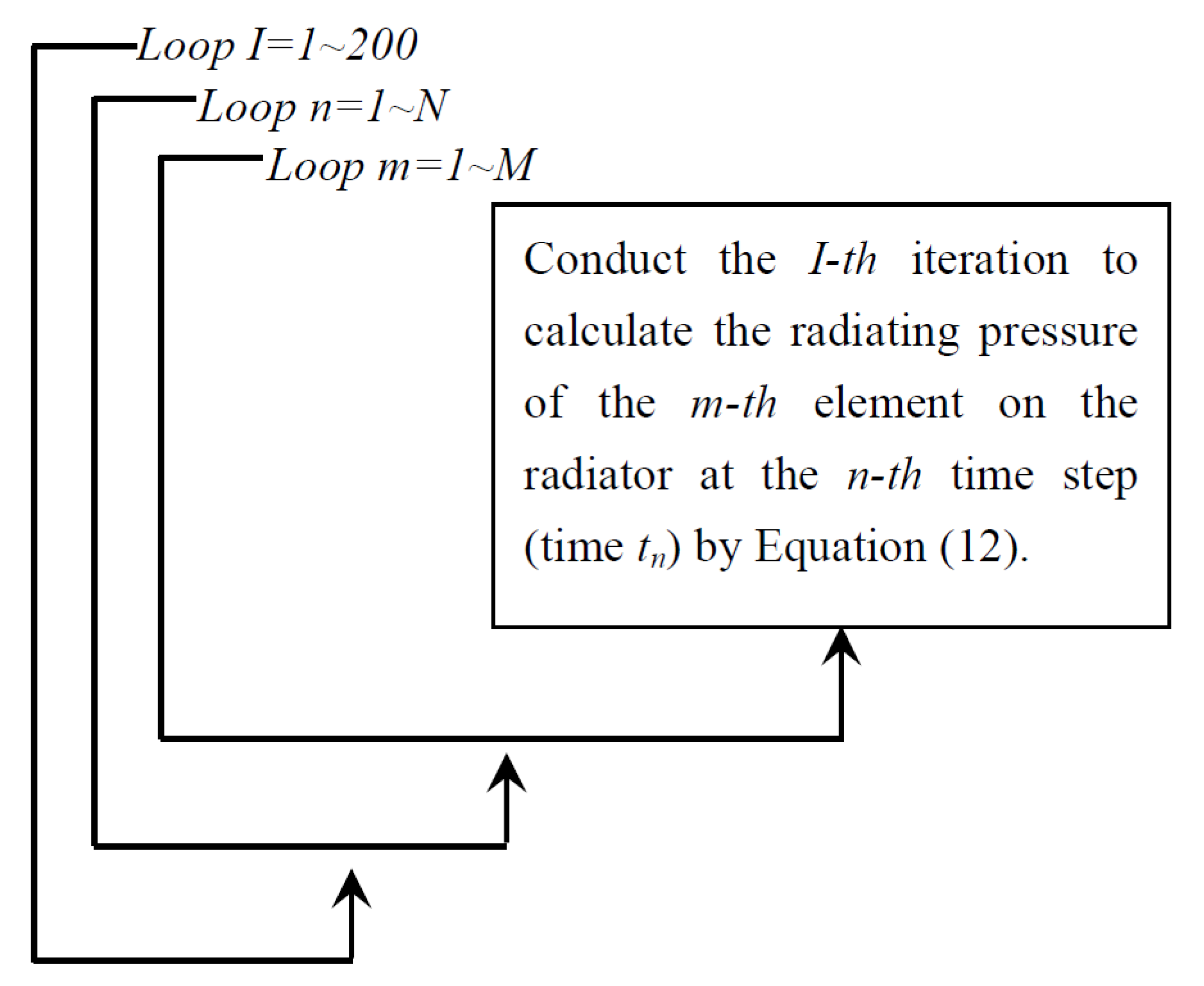
The radiating pressure of the field point is calculated by using Equation (14), and the iterating process is controlled by three outer loops, as illustrated in Figure 3. In the outermost loop, I refers to the Ith iteration. In the middle loop, n refers to different time steps. In the innermost loop, m refers to different elements on the pulsating object. Each iteration is performed from the first time step to the last time step (i.e., n = 1~N). At every time step, the radiating pressures of all elements (i.e., m = 1~M) are calculated. As the iterating process goes from the first time step to the Nth time step, the radiating pressure in one period of time (1/frequency) is calculated. The outer I loop is applied to repeat the iteration from the first time step to the Nth time step (i.e., one period). The calculated results of the previous I loop are used as the initial values for the current I loop. The outer loop continues until the entire calculation converges. In this paper, N is defined as the total time steps within one period (1/frequency); thus, the outer I loop is necessary. If N is defined as the total number of time steps within several periods, the outer I loop can be removed by using a large value of N.
The iterating scheme illustrated in Figure 3 calculates the radiating pressure of the mth element on the radiator at the nth time step (time tn) by Equation (14) for several iterations. In the iterating process, the right-hand side of Equation (14) is calculated first. Then, the calculated value is used to update the value for the left-hand side of Equation (14). The values of initial radiating pressures are unknown and can be set arbitrarily. According to Kao and Kehr [13], the iterating results can robustly converge to correct values by setting zero initial values. Thus, the initial radiating pressure in this paper was also specified to be zero.
The pulsating frequency, ω J , is included in the sine function of B part . As ω J is equal to the eigenfrequency of the interior, B part results in numerical instability. However, in this paper, B part was reformulated in Equation (8). Consequently, the numerical instability due to the eigenfrequency of the interior problem could be improved.
B part (Equation (8)) can be considered as the boundary condition. The pulsating velocity specified on the surface is included in B part . As the transient problem is solved, more harmonics can be summed to describe the pulsating velocity specified on the surface. The proposed method will work for the transient problem with an arbitrary object.

3. Numerical Results

3.1. A Sphere Pulsating at Internal Resonance Frequencies

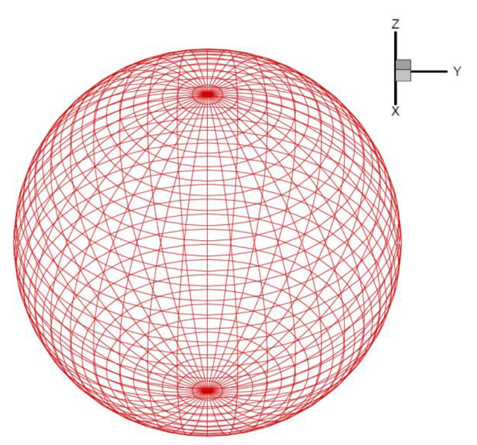
Figure 4 shows a pulsating sphere with a radius (R) of 1 m in an infinite air domain. The mean density of the air is 1.21 kg/m3, and the speed of sound is 343 m/s.

Internal Eigenfrequency Problem

The computing conditions are listed in Table 1, where K is the wave number. The pulsating frequencies are at eigenfrequency and high frequencies, i.e., KR = π~5. The normal velocity amplitude is assumed to be 1. It is noted that when KR is equal to π, the frequency 171.5 Hz is the first internal eigenfrequency. The number of elements is dependent on the factor l / λ . l is the maximum side length of the elements, and λ is the wavelength. The recommended value of l / λ is 0.065~0.069 according to the numerical tests carried out in this section. Moreover, the selection of the total number of time steps (N) can refer to the ratio of Δ t and the wave period. In this paper, this ratio ( Δ t / wave period) is 0.11~0.14, and robust convergence can be attained.
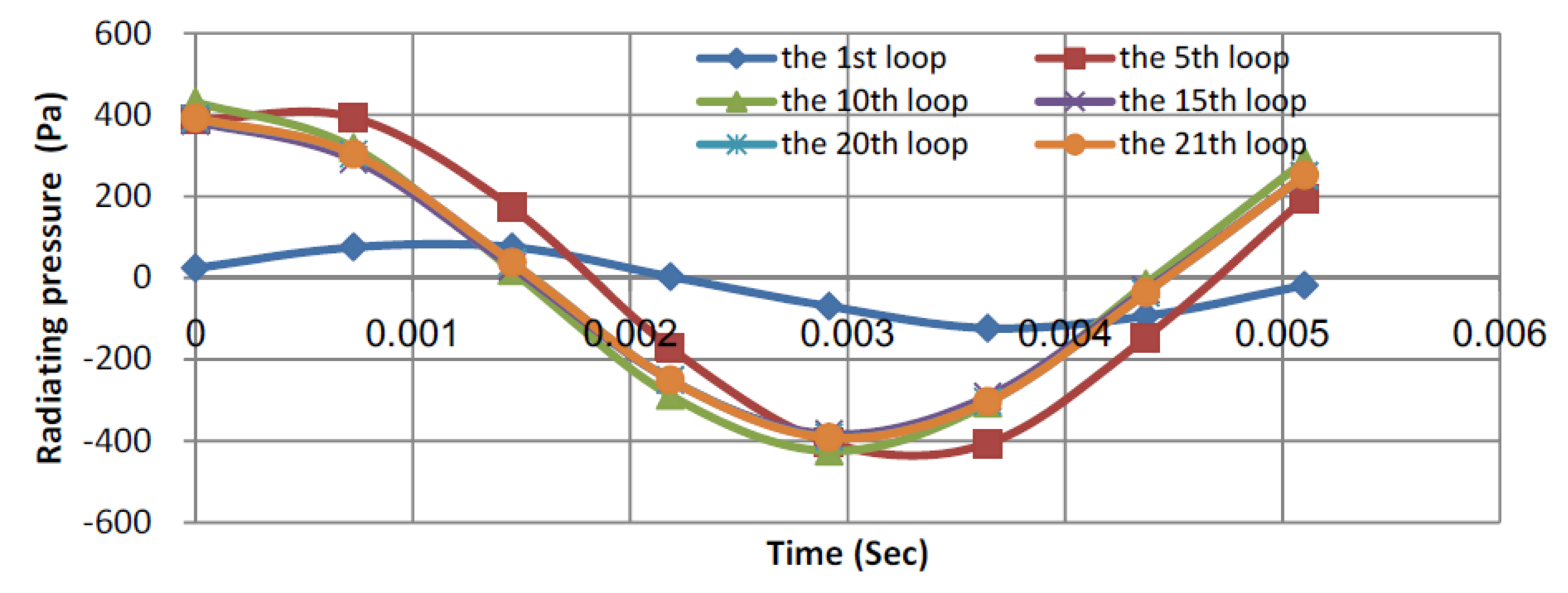
Figure 5a indicates that the iterating process is divergent at the first internal eigenfrequency without shifting the time step (F = 0 in Equation (4)). In Figure 5, the label on the X axis represents the Ith iteration carried out. On the Y axis, the label indicates the maximum absolute difference between two successive loops. P(tn)m,I is the radiating pressure of the mth element at the nth time step during the Ith iteration. Figure 5b shows that the present method with shifting of the time step (F = 0.35 in Equation (4)) can stabilize the numerical schemes at the first internal eigenfrequency and attain convergent results. The time-shifting factor—the F value in Equation (4)—for the first internal eigenfrequency is suggested to be 0.35 in Figure 5b. Figure 6 elaborates more on the convergence plot shown in Figure 5b. Figure 6 shows the iterating process of one element at different time steps for different iterating loops. Figure 6 indicates that a convergent result is attained after about 20 iterations. It was found that the results calculated by the 20th and 21st iterating loops were almost the same. In other words, the radiating pressures at different time steps were almost consistent for the 20th and 21st iterating loops, and convergence was achieved. Table 2 gives a comparison between the analytical and numerical solutions. The difference between the amplitudes of numerical and exact solutions defines the error value. The radiating pressure calculated by the present method with shifting time (F = 0.35) is 392 Pa, and the analytical solution is 395.48 Pa. The error is therefore below 1%.
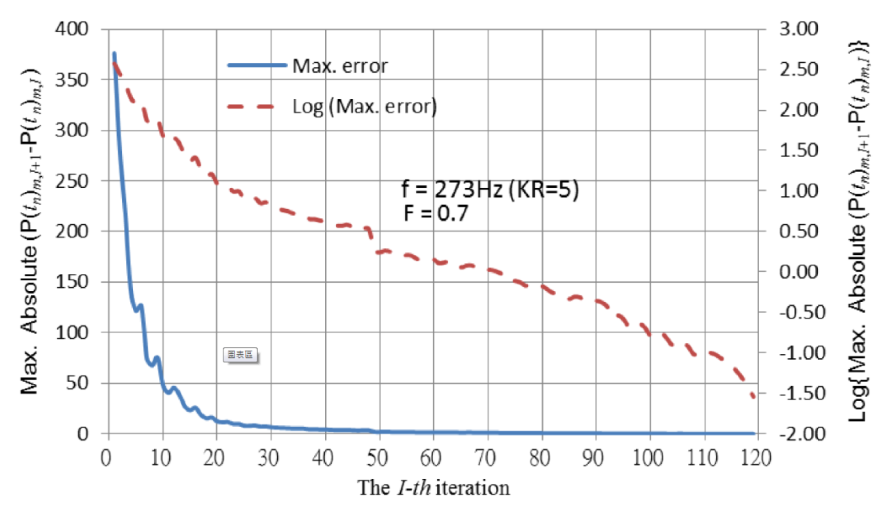
Figure 7 plots the convergence history for 218.4 Hz (KR = 4). In Figure 7, the time shift was also applied (F = 0.35), and the convergence was robust. The error between the numerical and analytical solutions at 218.4 Hz (KR = 4) is 1.29%, as shown in Table 2. In Figure 8, another time-shifting factor (F = 0.7) was tested, and the pulsating frequency was increased to 273 Hz (KR = 5), suggesting that the iterating process is stable and convergent. The difference between the numerical and analytical solutions is 1.54%, as listed in Table 2.
This computing sample illustrates that the present boundary element method can effectively improve numerical instability due to the internal eigenfrequency and robustly calculate the radiating wave at high frequency. The 0.35~0.7 range for the time-shifting factor (F) is recommended. The suggested ratio of maximum element side and wave length is under 0.069, showing that the numerical solution compares well with the analytical case; thus, the present method is both stable and reliable. In this paper, the midpoint rule was used to replace the surface integral. When the quadrangular elements were replaced by triangular elements, the error rate increased up to 0.63%, suggesting that quadrangular elements are more suitable for the present scheme.

3.2. An Arbitrary Radiator in the Half-Space Domain

As shown in Figure 1, an arbitrary object that is symmetric in the XY plane was treated as the studied case. Figure 1 can be considered as the half-space problem, and the infinite plane was assumed to be rigid (i.e., positive image) in this paper. The pulsating amplitudes and radiating pressures on the symmetrical part are positive with respect to the actual part. The actual part is composed of a cube (Faces 1~4) and a pyramid (Face 5). The side length of the cube is 1 m. The arbitrary geometry includes sharp edges, an apex, and an enormous variation in curvature. The center is at (0, 0, 0). The mean density of the air is 1.21 kg/m3, and the speed of sound is 343 m/s. The number of elements on the object is 1960.

3.2.1. Internal Eigenfrequency Problem

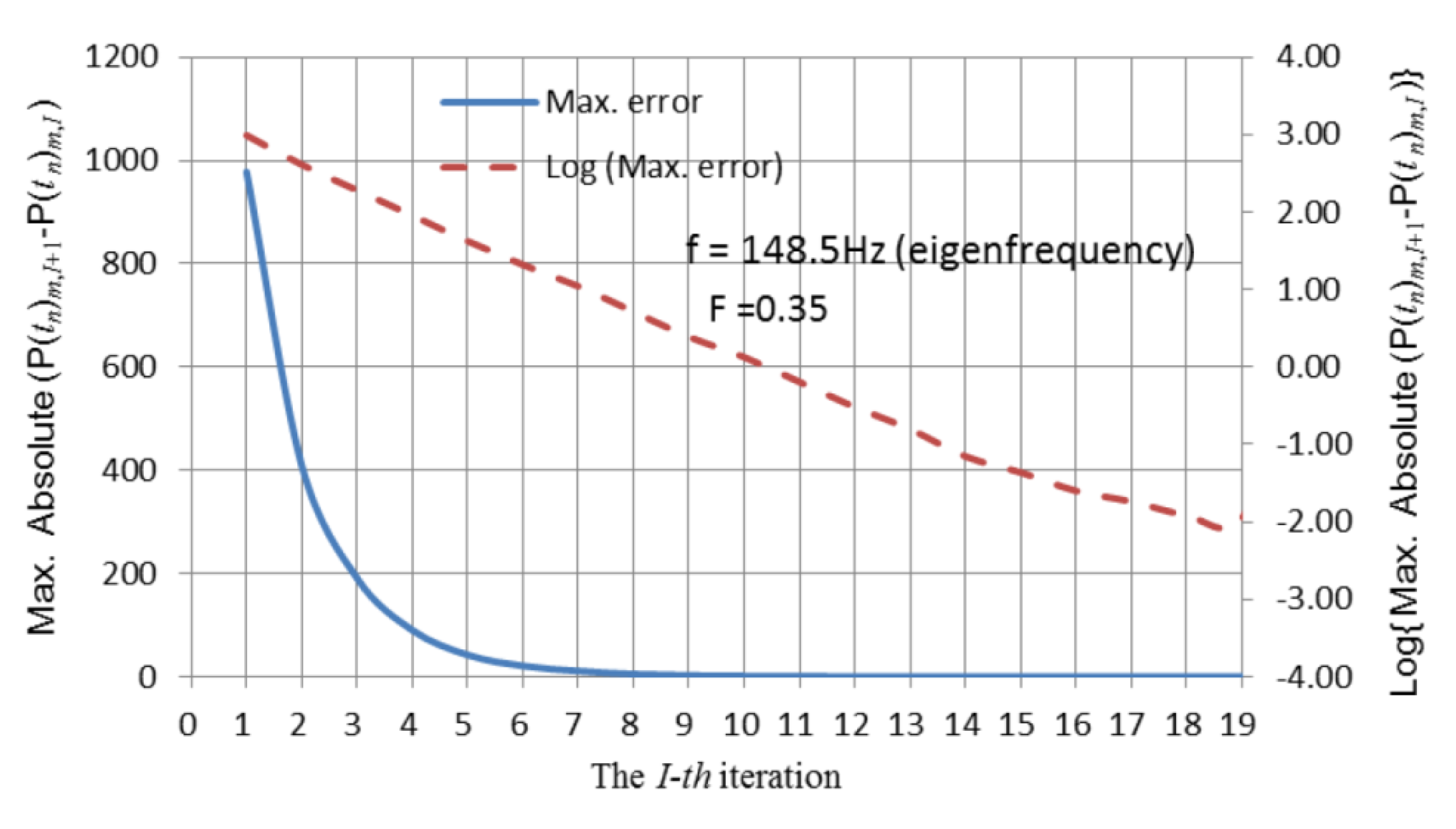
The arbitrary symmetric object shown in Figure 1 pulsating at the second internal resonance frequency (148.5 Hz) in an infinite air domain was also calculated using the present method with F = 0.35. The normal velocity amplitude was assumed to be 1. The convergence history illustrated in Figure 9 is robust.
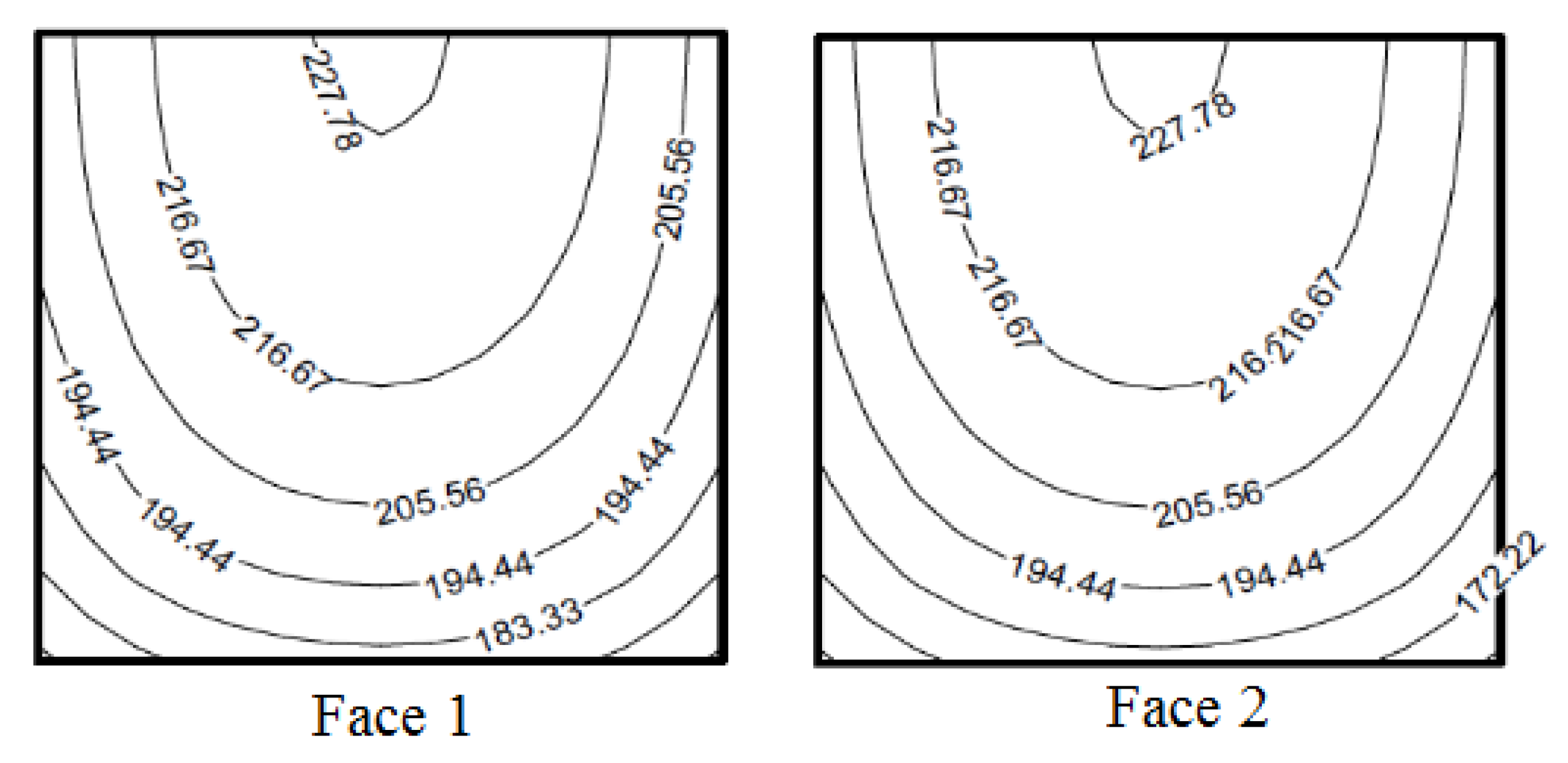
The amplitudes of the radiating pressures are shown in Figure 10. The amplitudes in Figure 10a,b are almost the same because the geometry of this radiator is bilaterally symmetrical. As the elements are closer to the XY plane, the radiating amplitudes are stronger due to the positive symmetry. Face 5 is a symmetrical cone; thus, the amplitude distribution on Face 5 plotted in Figure 10c is also symmetrical, and the center of the symmetry is the center of Face 5.

3.2.2. Multifrequency Problem

The object pulsates at multiple frequencies, and the multiple frequencies are not integer multiples, as listed in Table 3. The selected frequencies are far from the internal eigenfrequencies; thus, a time-shifting factor is unnecessary (F = 0 in Equation (4)) in this case.
The convergence history in Figure 11 shows that the convergence is robust. The amplitudes of the radiating pressure in the first harmonic on Faces 1 and 2 plotted in Figure 12 are reasonably identical. As the elements are closer to the XY plane, the radiating amplitudes are stronger due to the positive symmetry.

3.3. A Complex Object with an Indented Surface

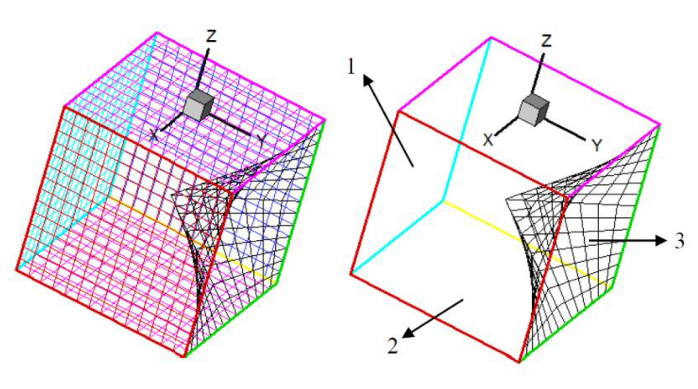
A cube immersed in an infinite domain, as shown in Figure 13, was considered. The cube has a complex shape with sharp edges and an indented surface. The length of the side of the cube is 5 m. A point source was placed inside the body at (0 m, 0 m, −2.5 m). The number of elements on the object is 980.

3.3.1. Internal Eigenfrequency Problem

The first internal resonance frequency of the irregular cubic indicated in Figure 13 is 31.3 Hz. It was assumed that this irregular cubic pulsates in an infinite air domain at 31.3 Hz, and the normal velocity amplitude is 1. The mean density of the air is 1.21 kg/m3, and the speed of sound is 343 m/s.
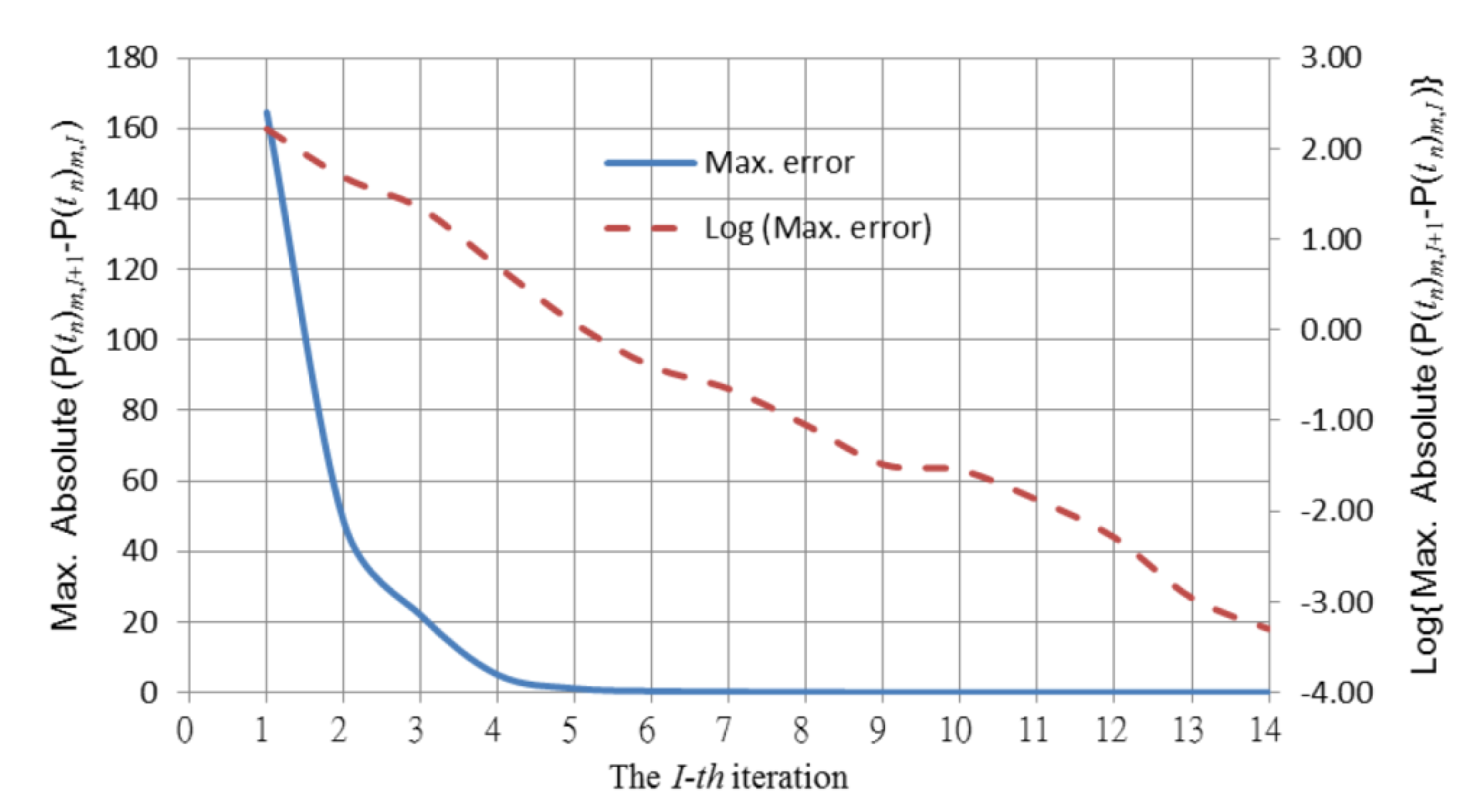
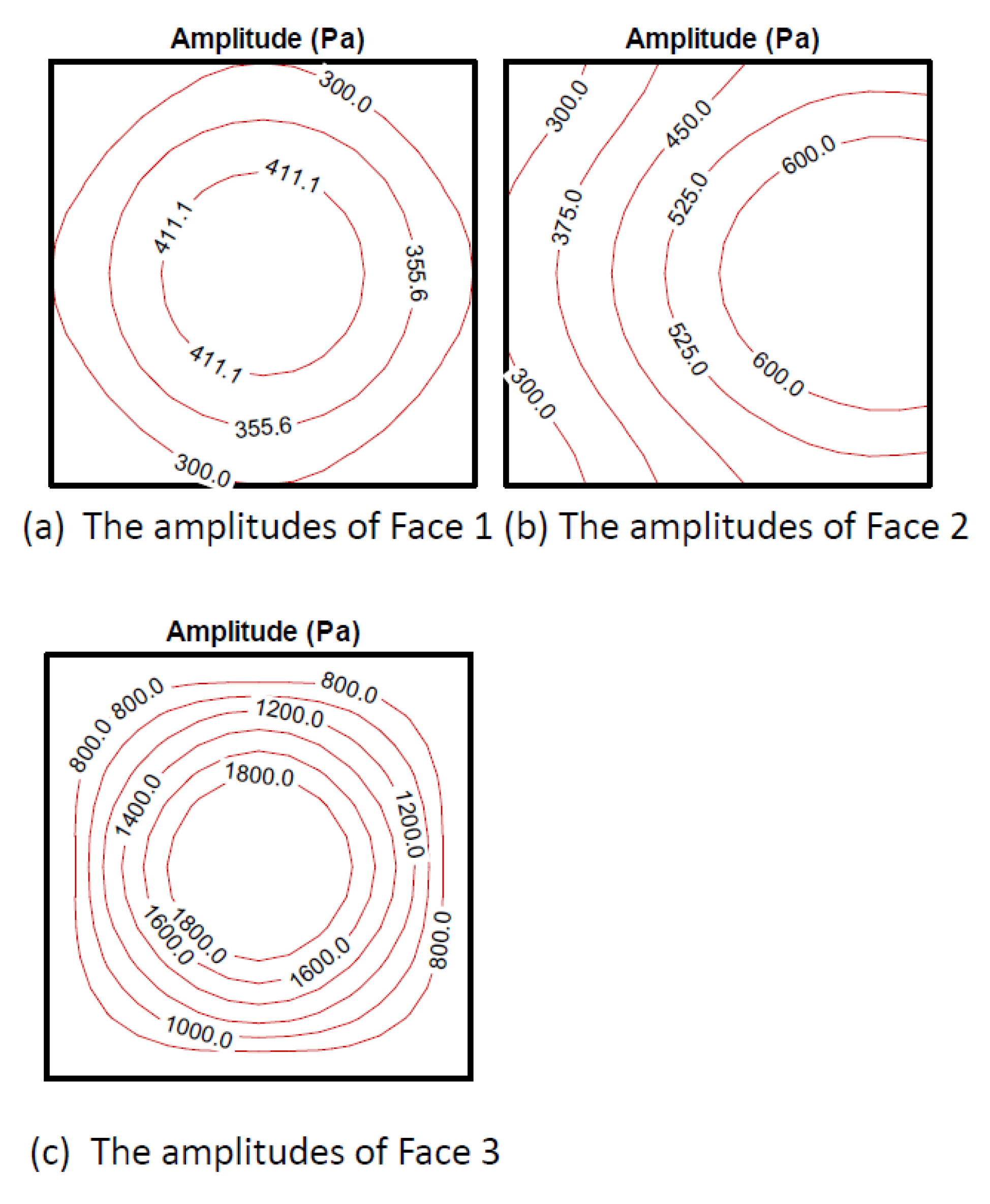
The iterating history obtained by the present method with F = 0.35 in Equation (4) is robustly convergent, as shown in Figure 14. Figure 15 illustrates the amplitudes of the radiating pressure. The symmetrical center of this irregular cubic is the center point of Face 3. Therefore, the amplitudes on Faces 1 and 3 shown in Figure 15a,c are distributed like concentric circles.

3.3.2. A Problem with Known Solutions

It was assumed that the object is immersed in an infinite water domain. The mean density of the water is 1000 kg/m3, and the speed of sound is 1500 m/s. The wave propagated from the point source was assumed to be spherical:
φ ( t ) = Re [ e i k r p r p   e i   ( 2   π   f )   t ] = Re [ e i ω ( t r p c ) r p ] = Re ( e i ω t s r p ) ( m 2 / s ) ,
where r p is the distance between the point source and any point on the object surface, f is the frequency (f = 50 Hz), and φ is the velocity potential of the wave.
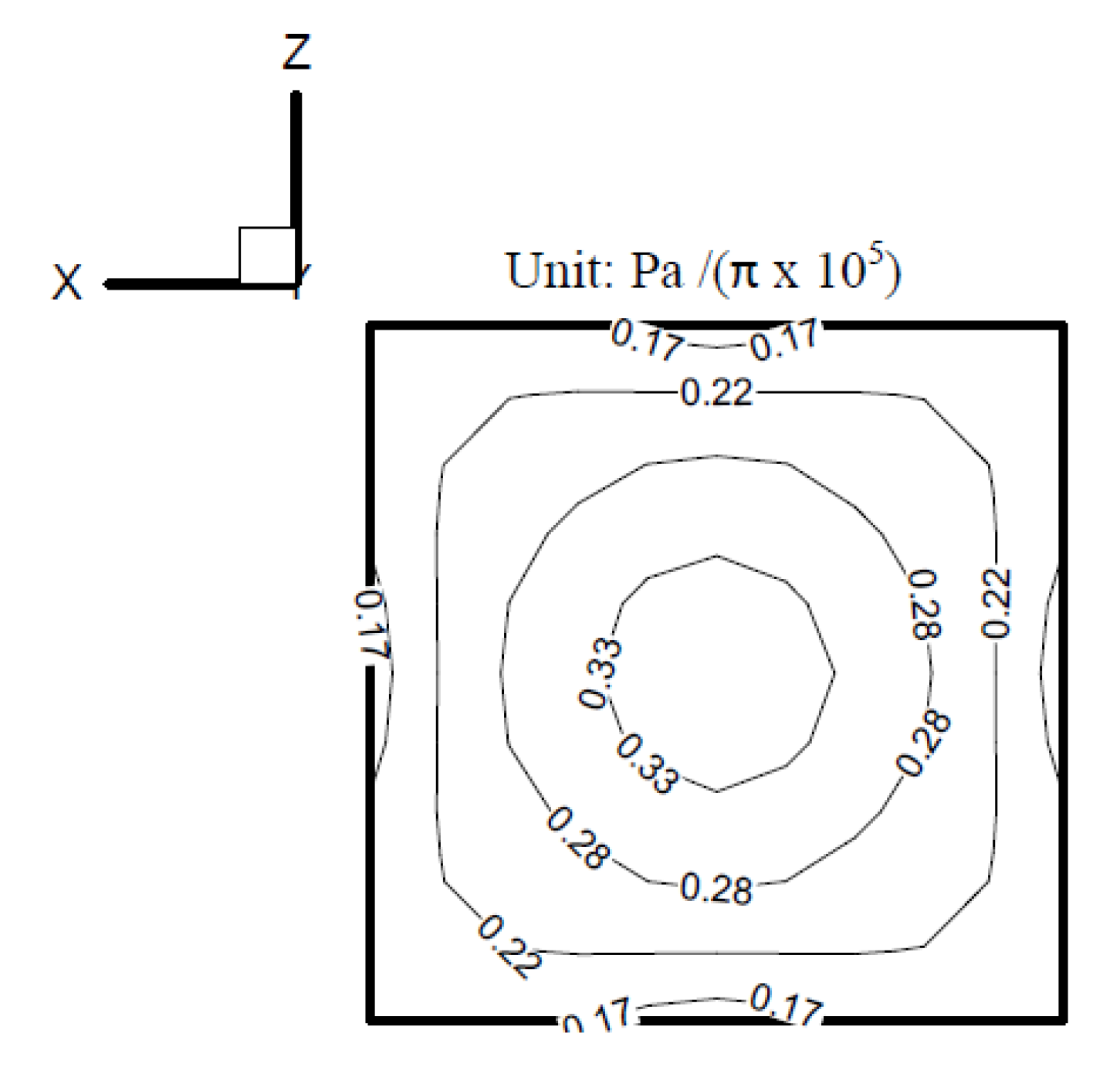
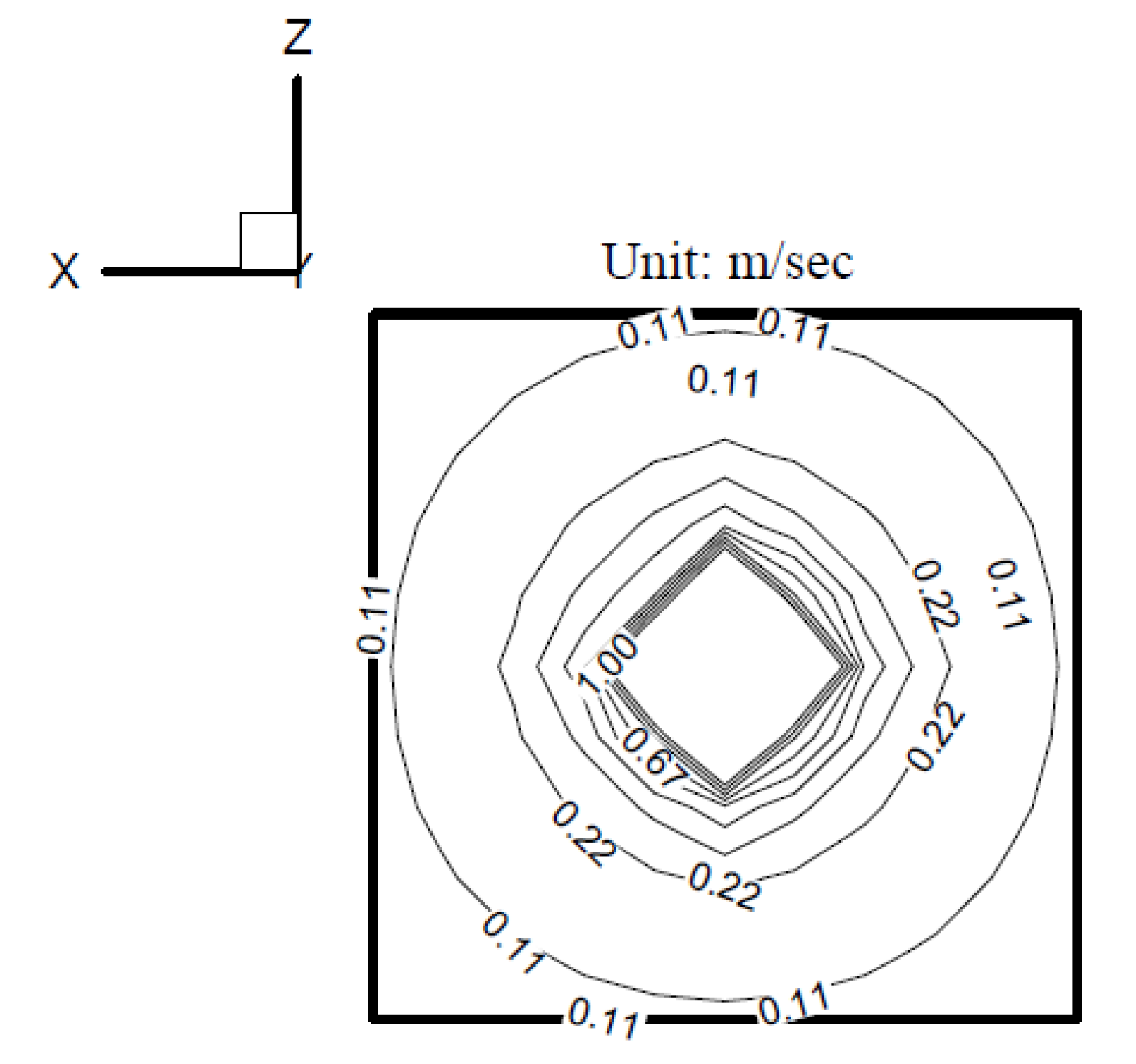
According to the BEM in Wu [24], the amplitude of the radiating pressure at 50 Hz, computed by using the point source on the indented surface, is shown in Figure 16. The amplitude of the surface velocity at 50 Hz on the indented surface, computed by the point source, is shown in Figure 17.
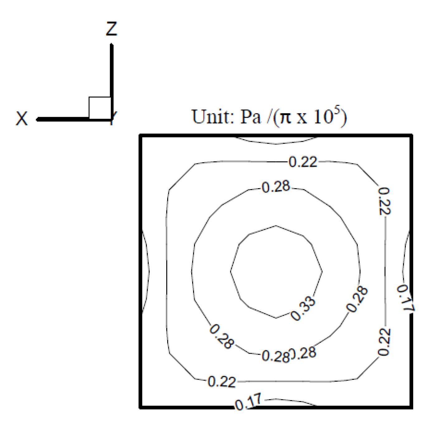
The radiating pressure on the indented surface at 50 Hz was also obtained by the present method using the boundary condition computed by the point source, as shown in Figure 13 and plotted in Figure 18. Here, the time shift is unnecessary (F = 0 in Equation (4)) because the frequency is far from the internal eigenfrequency. A comparison of Figure 16 and Figure 18 indicates that the result computed by the point source is almost the same as that by the present iterating scheme.

4. Conclusions

In this paper, an iterating boundary element method with a relaxation technique was derived in the time domain to solve the radiating waves from an arbitrary object pulsating at the interior resonance frequency.
The radiating pressures from a sphere pulsating with the first interior eigenfrequency and high frequencies were calculated by the present method, and when they were compared with the analytical solutions, they were shown to be in good agreement. A complex-shaped radiator in the half-space domain and an indented radiator in free space were also tested for the internal eigenfrequency problem and the multifrequency problem. The iteration results were robustly convergent for both problems.
Moreover, a point source with known solutions was placed inside the complex-shaped radiator to compute the surface velocities. The computed surface velocities on the indented surface were then used to solve the radiating pressures on the surface via the present method. The predicted radiating pressures exhibited good consistency with the known solutions.

Funding

This research received no external funding.

Institutional Review Board Statement

Not applicable.

Informed Consent Statement

Not applicable.

Data Availability Statement

The data presented in this study are available from the corresponding author, Jui Hsiang Kao, upon reasonable request.

Conflicts of Interest

The author declares no conflict of interest.

References

  1. Schenck, H.A. Improved integral formulation for acoustic radiation problem. J. Acoust. Soc. Am. 1968, 44, 41–58. [Google Scholar] [CrossRef]
  2. Burton, A.J.; Miller, G.F. The application of integral equation methods to the numerical solution of some exterior boundary–value problems. Proc. R. Soc. Lond. 1971, 323, 201–220. [Google Scholar]
  3. Lubich, C. Convolution quadrature and discretized operational calculus. I. Numer. Algorithms 1988, 52, 129–145. [Google Scholar] [CrossRef]
  4. Lubich, C. Convolution quadrature and discretized operational calculus. II. Numer. Algorithms 1988, 52, 413–425. [Google Scholar] [CrossRef]
  5. Ebenezer, D.D.; Stepanishen, P.R. Wave-vector-time domain and Kirchhoff integral equation methods to determine the transient acoustic radiation loading on circular cylinders. J. Acoust. Soc. Am. 1991, 89, 2532–2544. [Google Scholar] [CrossRef]
  6. Hwang, J.Y.; Chang, S.C. A retracted boundary integral equation for exterior acoustic problem with unique solution for all wave numbers. J. Acoust. Soc. Am. 1991, 92, 1167–1180. [Google Scholar] [CrossRef]
  7. Liu, Y.J.; Rizzo, F.J. A weakly singular form of the hypersingular boundary integral-equation applied to 3-d acoustic-wave problems. Comput. Methods Appl. Mech. Eng. 1992, 96, 271–287. [Google Scholar] [CrossRef]
  8. Lubich, C. On the multistep time discretization of linear initial-boundary value problems and their boundary integral Equations. Numer. Algorithms 1994, 67, 365–389. [Google Scholar] [CrossRef]
  9. Hwang, W.S. Hypersingular boundary integral equations for exterior acoustic problems. J. Acoust. Soc. Am. 1997, 101, 3336–3342. [Google Scholar] [CrossRef]
  10. Liu, Y.J.; Chen, S.H. A new form of the hypersingular boundary integral equation for 3-d acoustics and its implementation with c-0 boundary elements. Comput. Methods Appl. Mech. Eng. 1999, 173, 375–386. [Google Scholar] [CrossRef]
  11. Qian, Z.Y.; Han, Z.D.; Ufimtsev, P.; Atluri, S.N. Non-hyper-singular boundary integral Equations for acoustic problems, implemented by the collocation-based boundary element method. CMES-Comput. Model. Eng. Sci. 2004, 6, 133–144. [Google Scholar]
  12. Chappell, D.J.; Harris, P.J.; Henwood, D.; Chakrabarti, R. A stable boundary element method for modeling transient acoustic radiation. J. Acoust. Soc. Am. 2006, 120, 74–80. [Google Scholar] [CrossRef] [Green Version]
  13. Kao, J.H.; Kehr, Y.Z. A time-domain iteration method for acoustic scattering problems. J. Ship Res. 2006, 50, 334–343. [Google Scholar] [CrossRef]
  14. Hackbusch, W.; Kress, W.; Sauter, S.A. Sparse convolution quadrature for time domain boundary integral formulations of the wave Equation. IMA J. Numer. Anal. 2009, 29, 158–179. [Google Scholar] [CrossRef] [Green Version]
  15. Michael, S.; Martin, O.; Michael, M. Improving stability of the transient boundary element methodusing the CHIEF-Method. In Proceedings of the Congress in Sound and Vibration, Ljubljana, Slovenia, 15–18 September 2010. [Google Scholar]
  16. Jang, H.W.; Ih, J.G. Stabilization of time domain acoustic boundary element method for the exterior problem avoiding the nonuniqueness. J. Acoust. Soc. Am. 2013, 133, 1237–1244. [Google Scholar] [CrossRef] [PubMed] [Green Version]
  17. Qian, Z.Y.; Han, Z.D.; Atluri, S.N. A fast regularized boundary integral method for practical acoustic problems. CMES-Comput. Model. Eng. Sci. 2013, 91, 463–484. [Google Scholar]
  18. Christophe, L.; Alexandre, G. Solving the hypersingular boundary integral equation for the Burton and Miller formulation. J. Acoust. Soc. Am. 2015, 138, 3332–3340. [Google Scholar]
  19. Zhang, X.Z.; Bi, C.X.; Zhang, Y.B.; Xu, L. Sound source identification and sound radiation modeling in a moving medium using the time-domain equivalent source method. J. Acoust. Soc. Am. 2015, 137, 2678–2686. [Google Scholar] [CrossRef]
  20. Kao, J.H. A Weighting-Iteration Method in The Time Domain For Solving The Scattering Problem of a Complex-Shaped. Eng. Anal. Bound. Elem. 2016, 62, 7–12. [Google Scholar] [CrossRef]
  21. Kao, J.H. Applying a Step Approach Method in Solving The Multi-Frequency Radiation From a Complex Obstacle. CMES-Comput. Model. Eng. Sci. 2016, 112, 59–73. [Google Scholar]
  22. Bi, C.X.; Zhang, Y.; Zhang, X.Z.; Zhang, Y.B. Stability analysis of inverse time domain boundary element method for near-field acoustic holography. J. Acoust. Soc. Am. 2018, 143, 1308. [Google Scholar] [CrossRef] [PubMed]
  23. Burden, R.L.; Faires, J.D. Numerical Analysis; ITP Press: Boston, MA, USA, 1993. [Google Scholar]
  24. Wu, T.W. Boundary Element Acoustics; WIT Press: Southampton, UK; Boston, MA, USA, 2000. [Google Scholar]
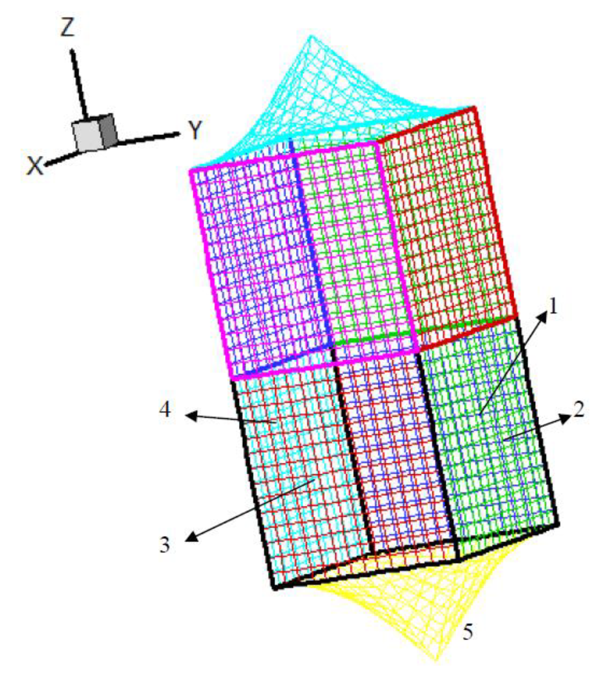
Figure 1. An arbitrary radiator in the half-space domain (Label 1–4: the square faces of the cubic, Label 5: the pyramid face).
Applsci 11 02701 g001
Figure 2. The illustration of the boundary element method with a relaxation technique.
Applsci 11 02701 g002
Figure 3. The iterating process for computing the radiating pressure.
Applsci 11 02701 g003
Figure 4. Sphere in an infinite air domain.
Applsci 11 02701 g004
Figure 5. Convergence history of the sphere pulsating at the eigenfrequency (KR = π).
Applsci 11 02701 g005
Figure 6. The iterative results of one element for different iterating loops.
Applsci 11 02701 g006
Figure 7. Convergence history of the sphere pulsating at the frequency KR = 4 (F = 0.35 in Equation (4)).
Applsci 11 02701 g007
Figure 8. Convergence history of the sphere pulsating at the frequency KR = 5 (F = 0.7 in Equation (4)).
Applsci 11 02701 g008
Figure 9. Convergence history of the arbitrary symmetric object pulsating at the internal resonance frequency of 148.5 Hz (F = 0.35 in Equation (4)).
Applsci 11 02701 g009
Figure 10. The radiating pressure on the arbitrary radiator at the second internal resonance frequency of 148.5 Hz (F = 0.35 in Equation (9)).
Applsci 11 02701 g010
Figure 11. Convergence histories of the arbitrary radiator for the arbitrary-frequency case.
Applsci 11 02701 g011
Figure 12. The first-harmonic radiating pressure on Faces 1 and 2 of the arbitrary radiator for the arbitrary-frequency case.
Applsci 11 02701 g012
Figure 13. A complex object immersed in an infinite domain (Label 1–2: the square surfaces of the cubic, Label 3: the indented surface).
Applsci 11 02701 g013
Figure 14. Convergence history of the irregular cubic pulsating at the internal resonance frequency of 31.3 Hz (F = 0.35 in Equation (4)).
Applsci 11 02701 g014
Figure 15. The radiating pressure on the irregular cubic at the first internal resonance frequency of 31.3 Hz (F = 0.35 in Equation (4)).
Applsci 11 02701 g015
Figure 16. The radiating pressure at 50 Hz computed by the point source on the indented surface.
Applsci 11 02701 g016
Figure 17. The amplitude of the surface velocity at 50 Hz on the indented surface computed by the point source.
Applsci 11 02701 g017
Figure 18. The radiating pressure at 50 Hz on the indented surface computed by the present method.
Applsci 11 02701 g018
Table 1. The selected frequencies and computing conditions for the pulsating sphere.
KRFrequency (Hz)Total Time Steps per Period (N)No. of Elements l / λ Δ t / Wave   Period
π171.587320.0650.14
4218.41011480.0670.11
5273.01016520.0690.11
l : the max. side length of the element; λ : the wavelength; KR: the production of the wave number and the sphere diameter.
Table 2. A comparison between the analytical and numerical results.
KRπ45
Frequency (Hz)171.5218.4273
Max. element size/wavelength0.06540.06670.0695
Exact solution (Pa)395.48402.6382406.97
Numerical solution (Pa)392397.5400.8
Error (%)0.89%1.29%1.54%
Exact phase angle of the pressure (deg)727679
Numerical phase angle of the pressure (deg)−857775
Table 3. Pulsating frequencies and amplitudes for the multifrequency case.
Normal Velocity Amplitude
(Vj, j = 1~2)
Corresponding Angular Frequency (ωj, j = 1~2)
V1 = 1ω1 = 2π × 20
V2 = 1ω2 = 2π × (20 × 1.5)
Publisher’s Note: MDPI stays neutral with regard to jurisdictional claims in published maps and institutional affiliations.