Article

Terahertz Spiral Spatial Filtering Imaging

1
Aerospace Information Research Institute, Chinese Academy of Sciences, Beijing 100094, China
2
Key Laboratory of Electromagnetic Radiation and Sensing Technology, Chinese Academy of Sciences, Beijing 100190, China
3
School of Electronic, Electrical and Communication Engineering, University of the Chinese Academy of Sciences, Beijing 100049, China
*
Author to whom correspondence should be addressed.
Appl. Sci. 2021, 11(6), 2526; https://doi.org/10.3390/app11062526
Submission received: 23 February 2021 / Revised: 7 March 2021 / Accepted: 9 March 2021 / Published: 11 March 2021
(This article belongs to the Special Issue Terahertz Optics, Beam Shaping and Imaging)

Abstract

:

Featured Application

This work presents great opportunities for the enhancement of THz image contrast.

Abstract

In this paper, we propose a terahertz (THz) spiral spatial filtering (SSF) imaging method that can enable image contrast enhancement. The related theory includes three main steps: (1) the THz image of the target is Fourier transformed to the spatial spectrum distribution; (2) the spatial spectrum is modulated by a spiral phase at the Fourier plane; (3) the filtered spatial spectrum is inverse Fourier transformed to the desired THz image. Meanwhile, analytic expression of the final THz image is derived. Due to the unique nature of the spiral phase, THz image contrast enhancement can be achieved and verified by various simulated target images with different contrasts. In our designed THz SSF imaging system, Fourier transform is carried out by the lens, and the spiral phase is acquired by the spiral phase plate (SPP). Proof-of-principle experiments with three different types of targets (carved metal letters, a high-density polyethylene (HDPE) piece with a scratch, and a leaf) were carried out, and the effectiveness of contrast enhancement and edge extraction on the THz reconstruction images was validated.

1. Introduction

For low-contrast amplitude and phase objects, traditional THz imaging methods cannot obtain terahertz (THz) images with ideal image contrast, which makes the subsequent edge-detection and feature-recognition stages of image processing difficult [1,2,3,4,5]. Therefore, developing a new THz imaging method for low-contrast objects is of great importance. As one of the last mastered frequency ranges of the electromagnetic spectrum, the THz band provides great potential for modern imaging methods which have been widely applied in other spectral regions [6,7,8,9,10,11,12,13,14,15]. Notably, THz imaging techniques can be applied in various fields, such as security screening [16,17], non-destructive testing [18,19,20], biological detection [1,21], and data-rata communications [22,23]. The implementation of such imaging techniques is influenced by various source types with fundamental generation differences [24]. In addition, spatial filtering imaging is an effective method for optimizing image quality, which is implemented by inserting a spatial filter in the Fournier plane. Various optical approaches of spatial filtering imaging have been developed to improve image resolution, image contrast, and achieve edge enhancement [25,26,27,28,29]. Spiral spatial filtering (SSF) imaging, as an optical implementation of the edge-enhancing transformation, offers a vital, convenient tool for edge detection in image processing. Due to the odd symmetry of the spiral phase, it is a prospective approach to enhance image contrast, not only in amplitude objects but also in phase objects [30]. Inspired by the SSF imaging demonstrated in the visible and infrared range of the electromagnetic spectrum, this technique can be extended to the THz band and is expected to present great opportunities for the enhancement of THz image contrast.
SSF imaging originated from radial Hilbert transforms, which was demonstrated by Davis et al. in 2000 [31]. Subsequently, the theories and experiments related to SSF imaging developed further. In 2005, Fürhapter et al. applied SSF imaging to light microscopy [32] and demonstrated that the spiral phase can improve the imaging contrast, with the experiments revealing good image quality. In 2006, Guo et al. proposed a radial Hilbert transformation with Laguerre–Gaussian spatial filters (LGSF) [33] and demonstrated that the LGSF possesses various advantages in comparison with the conventional spiral phase. In 2018, Qiu et al. proposed an imaging method in nonlinear optics using a nonlinear spatial filter, where the phase objects—using invisible illumination—can be converted into visible high-contrast images [30]. An early attempt at enhancing THz image contrast was made in 2001 by Fitzgerald et al. [34]. They proposed THz dark-field imaging based on the THz time-domain spectrometer (TDS) to enhance image contrast. The THz power was low in this system and the dark-field imaging resulted in the loss of most of the energy, which yielded a low signal to noise ratio (SNR) of the THz images. To improve the image contrast, Linas et al. proposed the Bessel zone plate design based on silicon multi-phase diffractive optics, which was demonstrated in continuous wave mode at 0.6 THz [35]. Despite significant experimental and theoretical progress in this area, SSF imaging at the THz band is still not satisfactory.
Here, we propose a THz SSF imaging technique that enables contrast enhancement of the target with low image contrast. THz SSF imaging inherits both the advantages of THz imaging and SSF imaging simultaneously, which is an effective way to enable THz high-contrast imaging. In our work, the SSF imaging principle at the THz frequency is analyzed. Based on such analysis, simulations and experiments were later carried out. From the simulated imaging results, it is noted that the proposed image technique can effectively enhance the image contrast of the target. In the experiments, we built a THz SSF imaging system based on a THz quantum cascade laser (THz-QCL) 4f imaging system. As it is a light source, the THz-QCL emits a power of 0.3 mW at 3.7 THz. In this 4f imaging system, a spiral phase plate (SPP) designed from high-density polyethylene (HDPE) at 3.7 THz is placed in the Fourier plane to obtain the spiral phase information. Carved metal letters, a HDPE piece with a scratch, and a leaf were tested in the imaging system. Edge extraction and contrast enhancement were demonstrated perfectly, which is in good agreement with the theory and simulation results. We believe that this THz imaging technique could pave the way for edge detection and contrast enhancement in THz imaging.

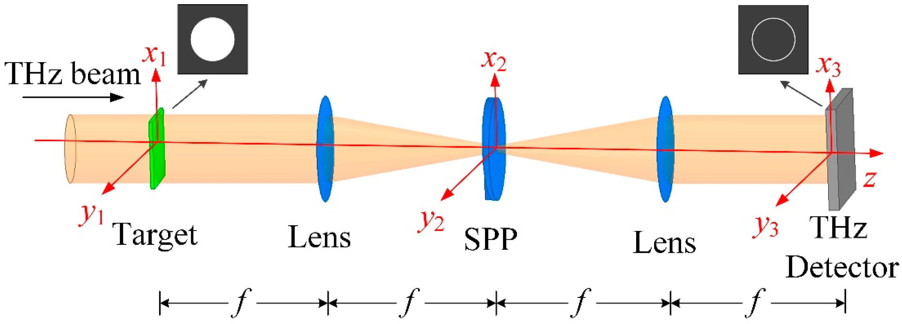
2. Theory of SSF Imaging
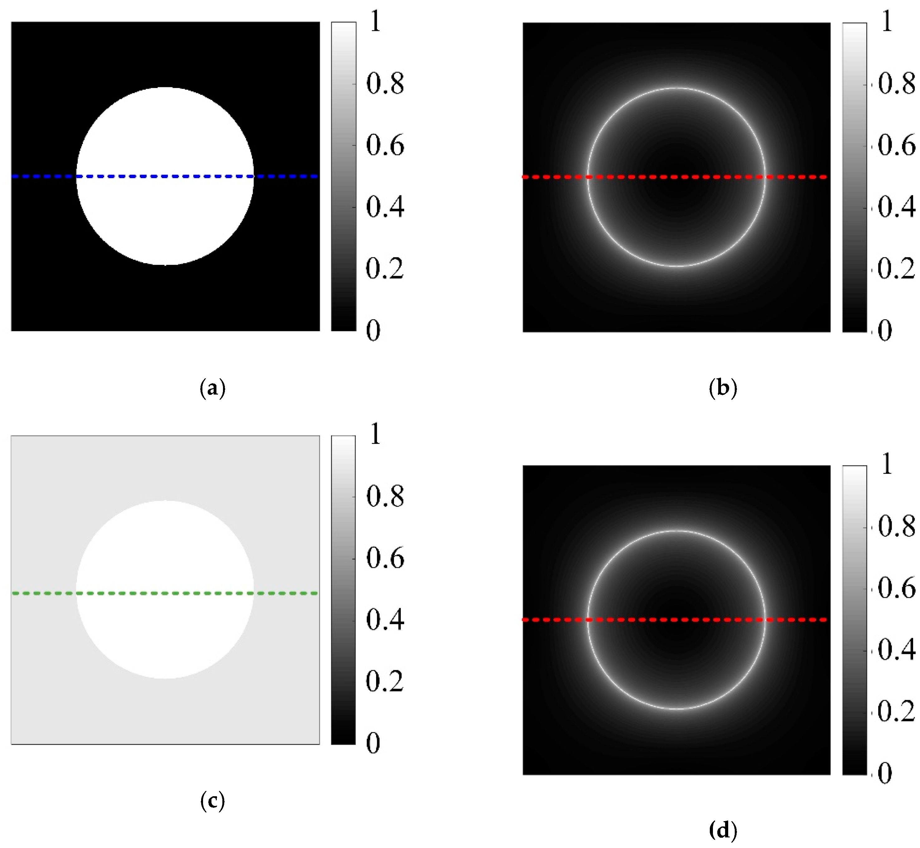
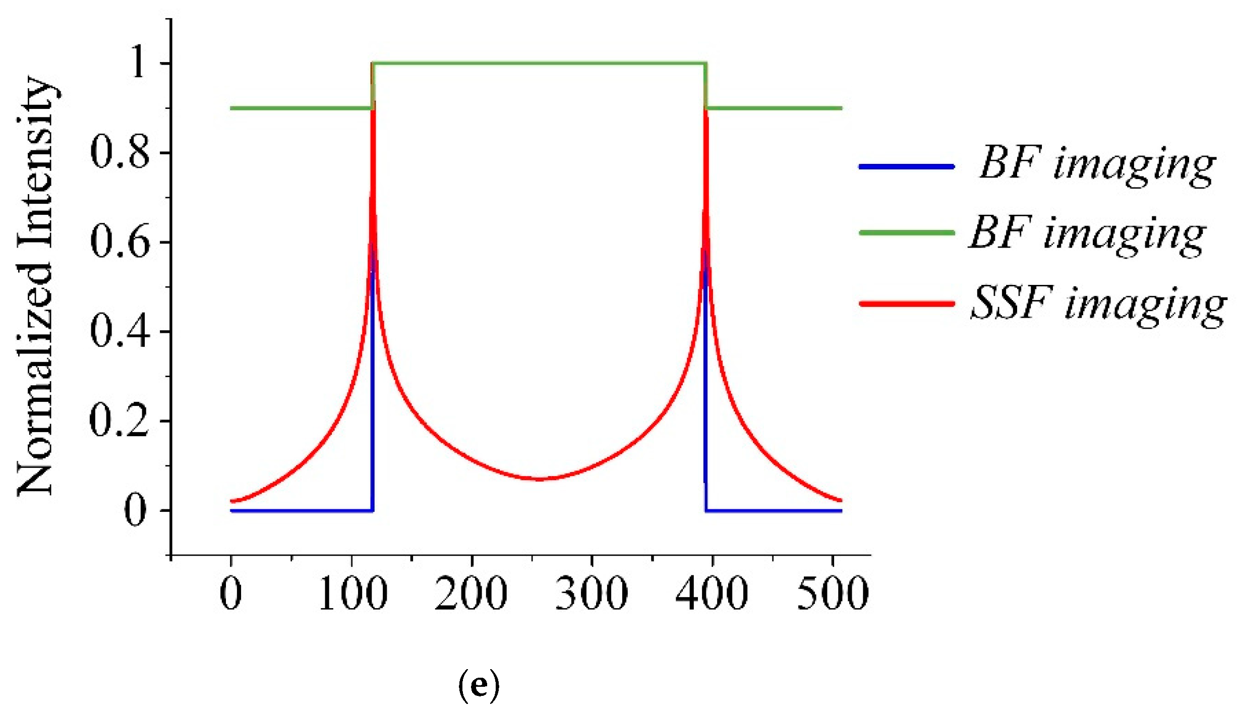
Figure 1 illustrates the schematic of a THz SSF imaging system, which is based on a 4f imaging system consisting of two convex lenses with the same focal length f. The target is located at the front focal plane of the first lens, and the detector is located at the back focal plane of the second lens. As the SPPs have the advantages of high purity and high conversion efficiency compared to the computational holograms (CHGs) and the metamaterials, a SPP is chosen and placed at the Fourier plane for generating the spiral phase.
Assume that a target O(x1, y1) is illuminated by a collimated THz beam, where (x1, y1) denotes the Cartesian coordinate of the target plane. After passing through the target, the THz electric field located at the back surface of the target can be expressed as E1(x1, y1), which can also be called the THz image of the target.
The lenses in the 4f imaging system play the role of Fourier transform, and the SPP acts as a filter that changes the spatial distribution of THz beam at the Fourier plane. In the Fourier plane, the THz electric field E2 (x2, y2) can be written as
E 2 ( x 2 , y 2 ) = F { E 1 ( x 1 , y 1 ) } H ( ρ )
where the symbol F { } represents the Fourier transform, and (x2, y2) denotes the Cartesian coordinate of the Fourier plane. H(ρ) is the modulation function of the SPP, and it can be expressed as
H ( ρ ) = circ ( ρ R ) e j θ
where ρ is the polar radius in the Fourier plane, circ(ρR) is the circular function describing an SPP with a radius of R, and θ is the azimuth in the Fourier plane.
The THz electric field can be obtained at the THz detector, which reads
E 3 ( x 3 , y 3 ) = F { E 2 ( x 2 , y 2 ) } = E 1 ( x 3 , y 3 ) | x 3 = x 1 , y 3 = y 1 F { H ( ρ ) }      
where E 1 ( x 3 , y 3 ) | x 3 = x 1 , y 3 = y 1 reverses the THz image E1 (x1, y1), and F { H ( ρ ) } represents the point spread function (PSF) of the SPP, which can be expressed as [36]
h ( r ) = F { H ( ρ ) } = π R 2 r [ J 0 ( k R r f ) H 1 ( k R r f ) J 1 ( k R r f ) H 0 ( k R r f ) ] e j φ
where k is the wave vector, f is the focal length of the lens, Jm() is m th-order Bessel function of the first kind, and Hm() is m th-order Struve function. (x3, y3) denotes the Cartesian coordinate of the THz detection plane, r is the polar radius, φ is the azimuth.
Equation (3) suggests that the final THz image E3(x3, y3) received by the THz detector is the convolution of the THz image E1(x1, y1) and the PSF of the SPP. Since the PSF of the SPP decays quickly with the radius r, the effective convolution is restricted to nearby surrounding area of each image point. According to the convolution theorem, if the nearby surrounding area of the image point is a uniform area, convolution with exp() will make the image point 0. Therefore, the uniform background can be filtered out after the convolution. Instead, the edges between different intensities or phases will be highlighted, and the intensity distribution is proportional to the intensity gradient of the original THz image of the target. That is, the image contrast can be enhanced as the image background is suppressed and the edges stand out through the convolution.

3. Simulations

To validate the effectiveness of the proposed THz SSF imaging system, we first imaged the simulated circular objects with different image contrasts, as shown in Figure 2. The corresponding Fourier spectra were calculated by performing the Fourier transform, then, these were multiplied by the modulation function of the SPP, and the inverse Fourier transform of the product is the desired THz SSF imaging result. Two circles with the same radius, same transmittance of 100% and different background transmittances (0 and 90%) were simulated and are shown in Figure 2a,c, respectively. Define C = (ImaxImin)/(Imax + Imin) as the image contrast, where Imax and Imin are the maximum and minimum of the image. Thus, the image contrasts of the two simulated circular targets are 100 and 5.26%, respectively. Figure 2b,d shows the THz SSF images of the two simulated circular targets. It is clearly shown that the energy concentrates at the edges and the energy levels inside the circles are suppressed. Both image contrasts of Figure 2b,d can be calculated as 100%. To compare the simulation results quantitatively, we marked the intensity distributions at same position in Figure 2 with the blue, green and red dashed lines. The corresponding normalized intensity distributions are shown in Figure 2e. Notably, the normalized intensity distributions for two circular objects are consistent, indicating that the resultant image contrasts after THz SSF imaging are consistent for the same targets with different image contrasts. Therefore, high-contrast targets can be used in experiments to verify the THz SSF imaging system. Meanwhile, the peaks of the THz SSF edge-enhanced images are located precisely on the edges of the circular objects, illustrating that the THz SSF imaging system has potential advantages in terms of edge detection.
Next, as shown in Figure 3, the effectiveness of the proposed THz SSF imaging system is further confirmed using the simulated letters object of “THz” with a transmittance of 100%, various backgrounds, and more edges than the circular objects (see Figure 3a,c,e). In order to simulate different image contrasts, the transmittances of backgrounds in Figure 3a,c,e are set as 30, 60, and 90%, respectively. Thus, the corresponding image contrasts are calculated as 53.85 (Figure 3a), 25 (Figure 3c), and 5.26% (Figure 3e), respectively. Figure 3b,d,f shows the simulated THz SSF imaging results corresponding to Figure 3a,c,e, respectively. Notably, the simulated imaging results exhibit a significant contrast enhancement (increasing to 100%), and the edges can be extracted perfectly.

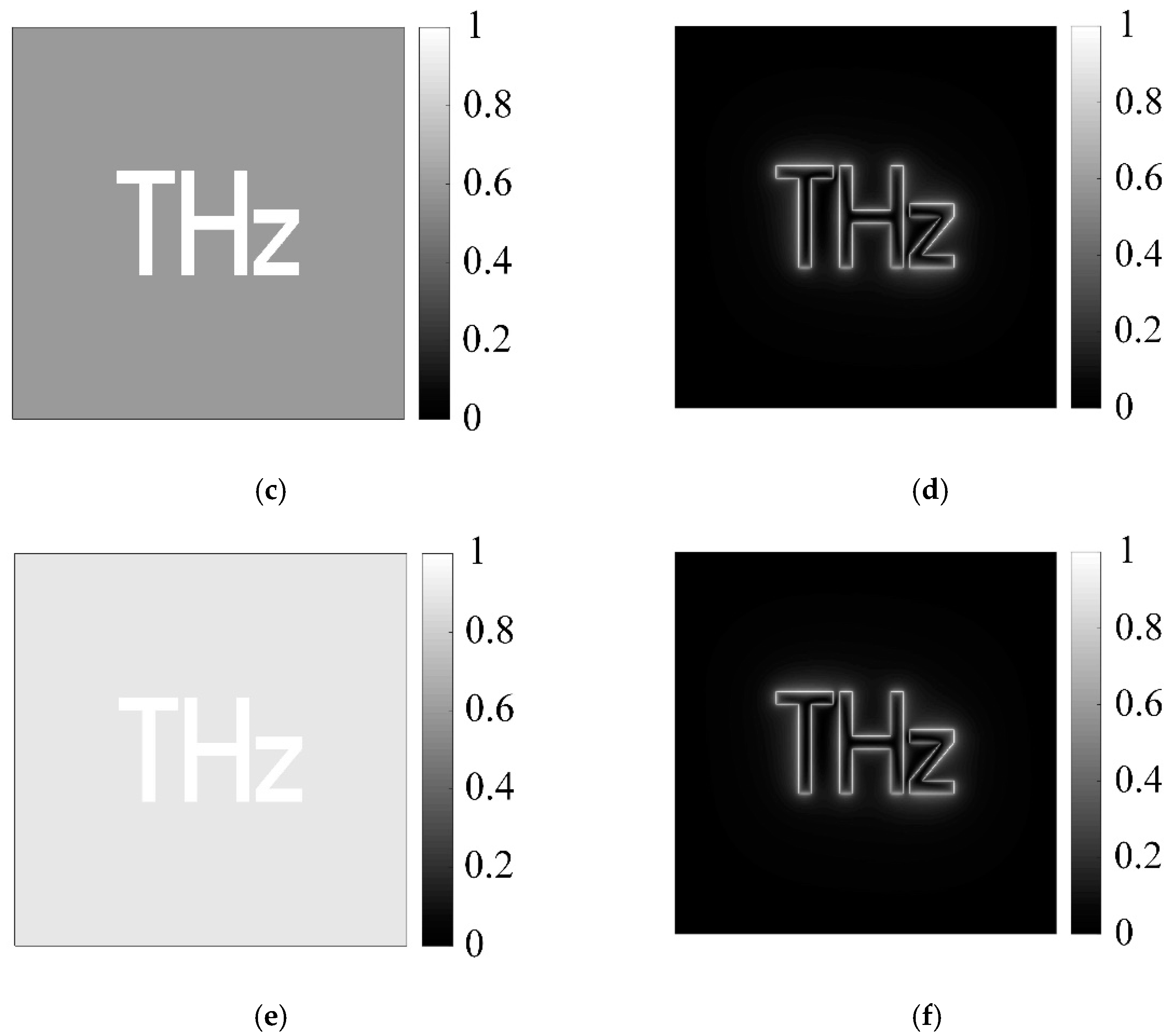
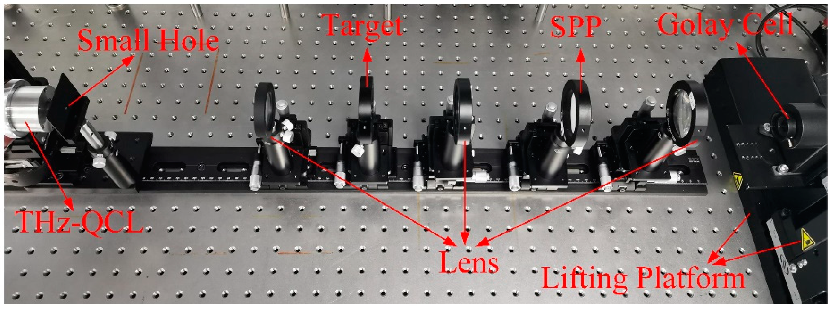
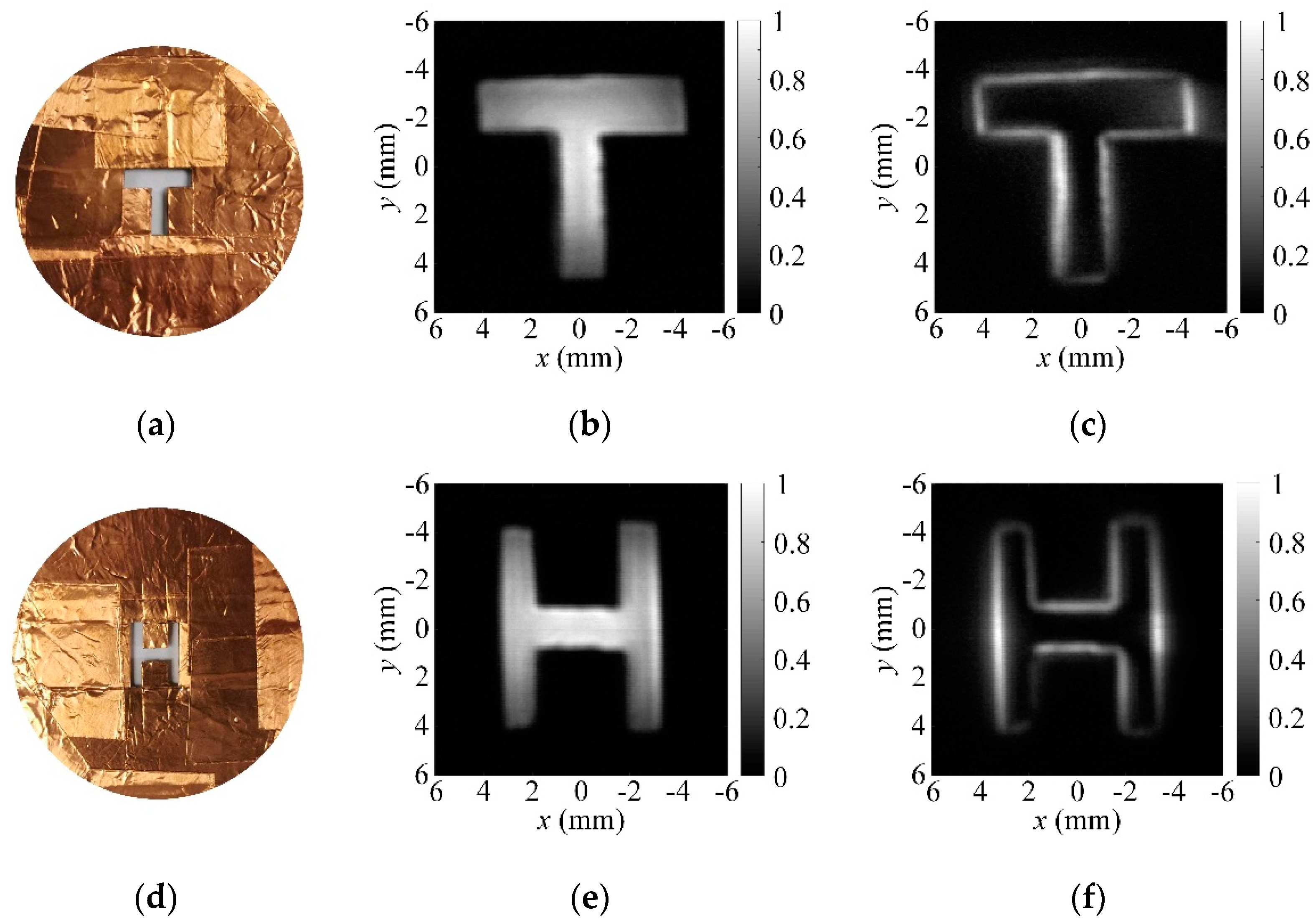
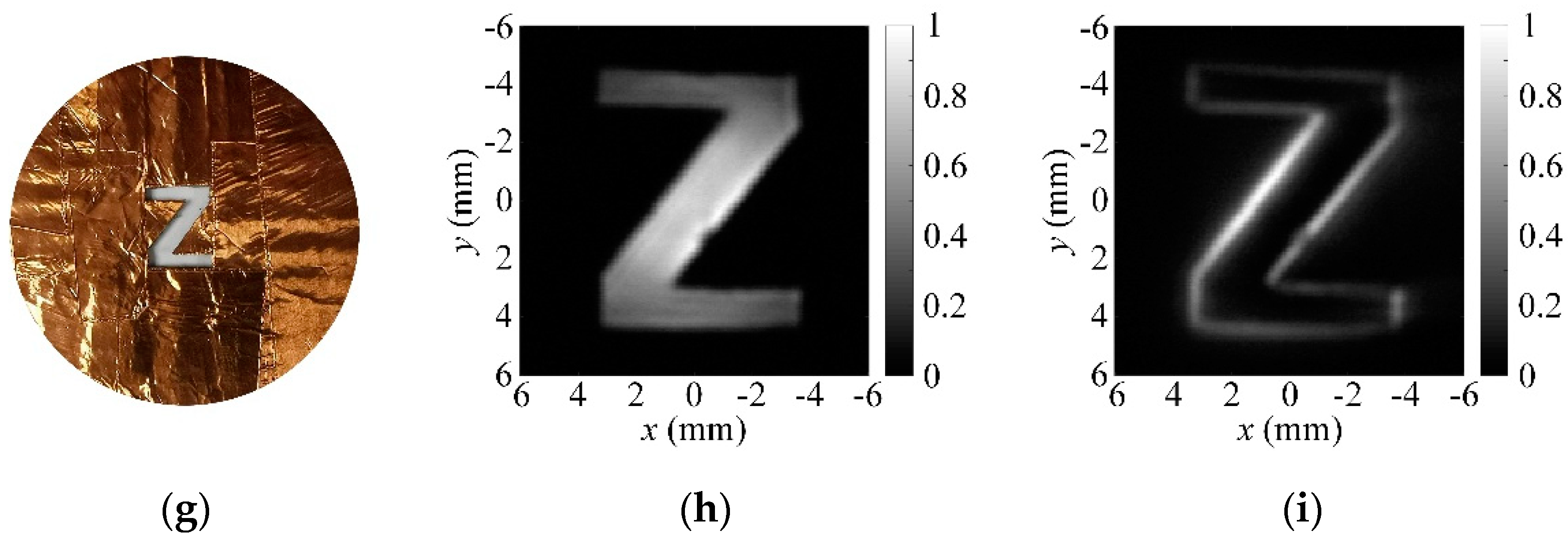
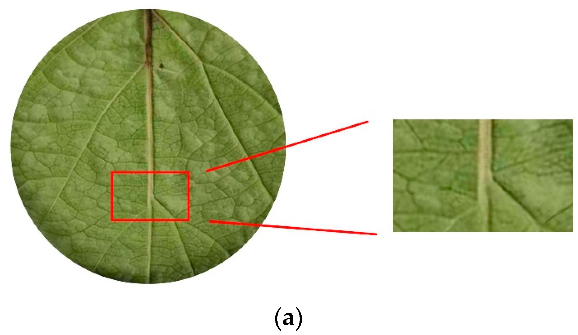
4. Experimental Results

To realize THz spiral spatial filtering imaging, we adopted a compact THz-QCL as the light source, and constructed a QCL-based setup with a 4f imaging scheme, as illustrated in Figure 4. The tested objects were illuminated by the QCL prototype, which was designed by the Institute of Semiconductors, Chinese Academy of Sciences, emitting 0.3 mW at 3.7 THz. A Golay cell with higher sensitivity and SNR was selected as the detector in the proposed THz SSF imaging system. The diameter of the entrance cone of the Golay cell was 11 mm, which is too large to act as a receiving aperture. A diaphragm was installed at the entrance cone of the Golay cell, which restricts the diameter of the receiving aperture of the Golay cell. In the experiments, the diaphragm was adjusted to the smallest aperture of 0.5 mm. The received THz signal was converted to the voltage signal in the Golay cell, and the voltage signal was digitized and recorded by a Stanford Research Systems Model SR830 DSP lock-in amplifier. To obtain THz images with a large imaging range, the Golay cell was mounted on a lifting platform, which was controlled by a scanning controller. The lifting platform can move 100 mm both in the x direction and y direction. As the optimum modulation frequency of the Golay cell is 15 ± 5 Hz, we input the modulation current of 10 Hz to the THz-QCL. In the experimental setup, an SPP designed from HDPE at 3.7 THz was placed in the Fourier plane and the focal length of the two ploymethylpentene (TPX) lenses in the 4f imaging system was 100 mm. The transmitted THz beam from the THz-QCL was reshaped by a small hole with 2 mm diameter, and the irregular THz beam was converted to a quasi-elliptical Gaussian beam. Then, the THz Gaussian beam was collimated by a TPX lens with a 200 mm focal length. After passing through the tested objects, the target information was modulated on the THz Gaussian beam. Finally, the beam enters the 4f imaging system and is detected by the Golay cell.
As typical high-contrast targets, the metal objects were selected to verify the THz SSF imaging. The cardboard wrapped in copper foil was used to make the targets. The letters “T”, “H” and “Z” were handmade using cardboard wrapped in copper foil. The letters have been cut off and can completely penetrate the THz wave, and other areas completely block the THz wave. The letters objects are shown in Figure 5a,d,g. In the experiments, to compare with the THz SSF images, the THz bright-field (BF) images are acquired by the THz SSF imaging system without the SPP. Figure 5b,e,h show the normalized THz BF images of the letters objects, indicating that the energies are concentrated inside the letters, and there are nearly no energies in other areas. The intensity distributions in the letters are nonuniform, which is caused by the quasi-elliptic Gaussian distribution of the THz beam. From the corresponding normalized THz SSF images shown in Figure 5c,f,i, the edges of the letters objects have been extracted perfectly. Meanwhile, it is clearly that the energies at the edges of ‘T’, ‘H’ and ‘Z’ are enhanced and the energies in the other region are suppressed. There might be two reasons to cause the uneven intensity distributions on the edges. First, the intensity distributions in the letters are not uniform. Second, there are certain phase errors due to the slight surface errors of the THz SPP. Although the intensities of the edges in experiments are not the same as the uniform edges in simulations, the experimental results are in general consistent with that in simulations, which validates the effectiveness of the SSF imaging in the THz frequency.
Further, we studied the capability of enhancing the imaging contrast of the tested object with low intensity and phase jumps of the THz SSF imaging system. As shown in Figure 6a, there is a hardly visible scratch on the HDPE piece, which was used as the testing object with low imaging contrast. The width of the scratch is about 0.6 mm, which is close to the size of the receiving aperture of the Golay cell. Therefore, the edges of the scratch were not extracted in the THz BF image (see Figure 6b). Notably, in comparison, it the much darker background in the THz SSF image is highlighted, as shown in Figure 6c. For a quantitative comparison, the intensity curves of the blue and red dashed lines at x = 0 mm and x = −2.5 mm are plotted in Figure 6d,e, respectively. For the THz BF images, the edge contrasts are calculated as only 45.59 (edge 1) and 45.52% (edge 2) for Figure 6d, and 26.02 (edge 3) and 31.16% (edge 4) for Figure 6e, respectively. The edge contrasts can be enhanced significantly after SSF imaging; they increase to 94.83 (edge 1) and 85.00% (edge2) for Figure 6d, and 85.20 (edge 3) and 62.15% (edge 4) for Figure 6e, respectively. Since the incident THz beam is a quasi-elliptic Gaussian beam, the beam is not zero after passing through the THz SSF imaging system, resulting in the background in the THz SSF image. Thus, the edge contrast is greatly enhanced after THz SSF imaging, but there are still weak background effect in the THz SSF images, leading to the edge contrast not being close to 100%, especially for edge 4 in Figure 6c.
Considering that imaging contrast enhancement for natural targets is more meaningful and challenging, we imaged a leaf using the proposed THz SSF imaging system (see Figure 7a). As different parts of the leaf have different the THz transmittances, a complex THz BF image was formed under the irradiation of the THz wave. From the THz BF image of the leaf shown in Figure 7b, the main veins and major lateral veins of the leaf are clearly visible. Meanwhile, some small lateral veins are blurred and some are even submerged by noise. The main vein and lateral veins are black in the THz BF image, indicating that these regions are nearly not transparent to the THz wave. For the regions partly transparent to the THz wave, the maximum transmittance is less than 35% due to the low SNR in the image. After THz SSF imaging, the resultant image is displayed in Figure 7c. The background of the THz BF image is clearly suppressed. The edges of main vein are acquired and most of the lateral veins are highlighted in the image. The edge contrasts of the specific the lateral veins are enhanced for the red marked areas 1, 2, and 3 in Figure 7c, which are blurred in Figure 7b.

5. Conclusions

In summary, we have proposed and implemented a THz SSF imaging system, which could be an effective way to achieve high contrast imaging at the THz frequency. For this purpose, we built a QCL-based 4f imaging system, and an SPP acting as a filter was placed at the Fourier plane. Firstly, the principle of the imaging method was analyzed, and the analytic expression of the high-contrast THz image was derived. Then, we imaged the targets with different image contrasts in the simulations and experiments. The edges of the targets can be extracted because of the enhanced imaging contrasts. This technique can allow us to directly access the outline profiles of objects under low image contrast conditions. As demonstrated, edge contrast enhancement was clearly observed in all the imaging experiments. Considering that there are no mature imaging methods to improve the contrast of the THz image at present, our technique could be a supplementary method to THz imaging.

Author Contributions

The research was performed by the authors as follows: Conceptualization, H.L.; methodology, H.L. and S.W.; software, H.L. and M.Z.; validation, H.L. and C.L.; formal analysis, H.L. and M.Z.; investigation, H.L. and G.F.; resources, X.L. and G.F.; data curation, H.L. and S.W.; writing—original draft preparation, H.L.; writing—review and editing, S.W.; visualization, H.L.; supervision, X.L. and G.F.; project administration, S.W. and C.L.; funding acquisition, G.F. All authors have read and agreed to the published version of the manuscript.

Funding

This work was supported by the National Key Research and Development Program of China under Grant (2018YFB2202500, 2018YFF01013004), the National Natural Science Foundation of China (61971397, 61501424, 61671432, 61731020 and 61988102), and the Beijing Municipal Natural Science Foundation under Grant 4172066.

Institutional Review Board Statement

Not applicable.

Informed Consent Statement

Not applicable.

Conflicts of Interest

The authors declare no conflict of interest.

References

  1. Nakajima, S.; Hoshina, H.; Yamashita, M.; Otani, C.; Miyoshi, N. Terahertz imaging diagnostics of cancer tissues with a chemometrics technique. Appl. Phys. Lett. 2007, 90, 2549. [Google Scholar] [CrossRef]
  2. Wang, X.; Cui, Y.; Sun, W.; Ye, J.S.; Yan, Z. Terahertz real-time imaging with balanced electro-optic detection. Opt. Commun. 2010, 283, 4626–4632. [Google Scholar] [CrossRef]
  3. Rong, L.; Latychevskaia, T.; Chen, C.; Wang, D.; Yu, Z.; Zhou, X.; Li, Z.; Huang, H.; Wang, Y.; Zhou, Z. Terahertz in-line digital holography of human hepatocellular carcinoma tissue. Sci. Rep. 2015, 5, 8445. [Google Scholar] [CrossRef] [Green Version]
  4. Locatelli, M.; Ravaro, M.; Bartalini, S.; Consolino, L.; Vitiello, M.S.; Cicchi, R.; Pavone, F.; Natale, P.D. Real-time terahertz digital holography with a quantum cascade laser. Sci. Rep. 2015, 5, 13566. [Google Scholar] [CrossRef] [PubMed] [Green Version]
  5. Humphreys, M.; Grant, J.P.; Escorcia-Carranza, I.; Accarino, C.; Kenney, M.; Shah, Y.D.; Rew, K.G.; Cumming, D.R. Video-rate terahertz digital holographic imaging system. Opt. Express 2018, 26, 25808–25813. [Google Scholar] [CrossRef] [PubMed]
  6. Ahi, K. Mathematical Modeling of THz Point Spread Function and Simulation of THz Imaging Systems. IEEE Trans. Terahertz Sci. Technol. 2017, 7, 747–754. [Google Scholar] [CrossRef]
  7. Service, R.F. New chip-based lasers promise practical terahertz imaging. Science 2020, 370, 647. [Google Scholar] [CrossRef] [PubMed]
  8. Wan, M.; Yuan, H.; Healy, J.J.; Sheridan, J.T. Terahertz confocal imaging: Polarization and sectioning characteristics. Opt. Lasers Eng. 2020, 134, 106182. [Google Scholar] [CrossRef]
  9. Yahyaei, B.; Panahi, O.; Moradiannejad, F.; Ghiasabadi, A.M. Ultra sub-wavelength resolution terahertz near-field imaging: Modelling via the FDTD method in a multi-pixel sampling approach. Lasers Phys. 2020, 30, 5. [Google Scholar] [CrossRef]
  10. Hu, B.B.; Nuss, M.C. Imaging with terahertz waves. Opt. Lett. 1995, 20, 1716–1718. [Google Scholar] [CrossRef]
  11. Darmo, J.; Tamosiunas, V.; Fasching, G.; Krll, J.; Debbage, P. Imaging with a Terahertz quantum cascade laser. Opt. Express 2004, 12, 1879–1884. [Google Scholar] [CrossRef] [PubMed]
  12. Danylov, A.A.; Goyette, T.M.; Waldman, J.; Coulombe, M.J.; Nixon, W.E. Terahertz inverse synthetic aperture radar (ISAR) imaging with a quantum cascade laser transmitter. Opt. Express 2010, 18, 16264–16272. [Google Scholar] [CrossRef]
  13. Stantchev, R.I.; Phillips, D.B.; Hobson, P.; Hornett, S.M.; Hendry, E. Compressed sensing with near-field THz radiation. Optica 2017, 4, 989–992. [Google Scholar] [CrossRef] [Green Version]
  14. Mittleman, D.M. Twenty years of terahertz imaging. Opt. Express 2018, 26, 9417–9431. [Google Scholar] [CrossRef]
  15. Li, Z.; Zou, R.; Kong, W.; Wang, X.; Deng, Q.; Yan, Q.; Qin, Y.; Wu, W.; Zhou, X. Terahertz synthetic aperture in-line holography with intensity correction and sparsity autofocusing reconstruction. Photonics Res. 2019, 7, 1391–1399. [Google Scholar] [CrossRef]
  16. Grossman, E.; Dietlein, C.; Ala-Laurinaho, J.; Leivo, M.; Gronberg, L.; Gronholm, M.; Lappalainen, P.; Rautiainen, A.; Tamminen, A.; Luukanen, A. Passive terahertz camera for standoff security screening. Appl. Opt. 2010, 49, 106–120. [Google Scholar] [CrossRef] [PubMed]
  17. Appleby, R.; Anderton, R.N. Millimeter-Wave and Submillimeter-Wave Imaging for Security and Surveillance. Proc. IEEE 2007, 95, 1683–1690. [Google Scholar] [CrossRef]
  18. Yakovlev, E.V.; Zaytsev, K.I.; Dolganova, I.N.; Yurchenko, S.O. Non-Destructive Evaluation of Polymer Composite Materials at the Manufacturing Stage Using Terahertz Pulsed Spectroscopy. IEEE. Trans. Terahertz Sci. Technol. 2015, 5, 810–816. [Google Scholar] [CrossRef]
  19. Zhang, Z.W.; Wang, K.J.; Lei, Y.; Zhang, Z.Y.; Zhao, Y.M.; Li, C.Y.; Gu, A.; Shi, N.C.; Zhao, K.; Zhan, H.L.; et al. Non-destructive detection of pigments in oil painting by using terahertz tomography. Sci. China Phys. Mech. 2015, 58, 1–2. [Google Scholar] [CrossRef]
  20. Zhang, L.L.; Karpowicz, N.; Zhang, C.L.; Zhao, Y.J.; Zhang, X.C. Real-time nondestructive imaging with THz waves. Opt. Commun. 2008, 281, 1473–1475. [Google Scholar] [CrossRef]
  21. Bowman, T.C.; Elshenawee, M.; Campbell, L.K. Terahertz imaging of excised breast tumor tissue on paraffin sections. IEEE. Trans. Antennas Propag. 2015, 63, 2088–2097. [Google Scholar] [CrossRef]
  22. Bashir, S.; Alsharif, M.H.; Khan, I.; Albreem, M.A.; Sali, A.; Ali, B.M.; Noh, W. MIMO-Terahertz in 6G Nano-Communications: Channel Modeling and Analysis. CMC-Comput. Mater. Contin. 2020, 66, 263–274. [Google Scholar] [CrossRef]
  23. Singh., P.; Kim, B.W.; Jung, S.Y. Compressed Detection for Pulse-Based Communications in the Terahertz Band. Wirel. Commun. Mob. Comput. 2018, 2018, 2408496. [Google Scholar] [CrossRef] [Green Version]
  24. Karpowicz, N.; Zhong, H.; Xu, J.; Lin, K.I.; Hwang, J.S.; Zhang, X.C. Comparison between pulsed terahertz time-domain imaging and continuous wave terahertz imaging. Semicond. Sci. Technol. 2002, 20, S293–S299. [Google Scholar] [CrossRef]
  25. Watkins, L.S. Inspection of integrated circuit photomasks with intensity spatial filters. Proc. IEEE 1969, 57, 1634–1639. [Google Scholar] [CrossRef]
  26. Pinnell, J.; Klug, A.; Forbes, A. Spatial filtering of structured light. Am. J. Phys. 2020, 88, 1123–1131. [Google Scholar] [CrossRef]
  27. Kumbham, M.; Mouras, R.; Mani, A.; Daly, S.; O’Dwyer, K.; Toma, A.; Bianchini, P.; Diaspro, A.; Liu, N.; Tofail, S.A.; et al. Spatial-domain filter enhanced subtraction microscopy and application to mid-IR imaging. Opt. Express 2017, 25, 13145–13152. [Google Scholar] [CrossRef] [PubMed] [Green Version]
  28. Martinez-Carranza, J.; Kozacki, T. Quantitative phase imaging with increased spatial coherence based on Fourier filtering. Opt. Lett. 2018, 43, 5435–5438. [Google Scholar] [CrossRef] [PubMed]
  29. Zhu, X.L.; Yao, H.N.; Yu, J.Y.; Gbur, G.; Wang, F.; Chen, Y.H.; Cai, Y.J. Inverse design of a spatial filter in edge enhanced imaging. Opt. Lett. 2020, 45, 2542–2545. [Google Scholar] [CrossRef] [PubMed]
  30. Qiu, X.; Li, F.; Zhang, W.; Zhu, Z.; Chen, L. Spiral phase contrast imaging in nonlinear optics: Seeing phase objects using invisible illumination. Optica 2018, 5, 208–212. [Google Scholar] [CrossRef]
  31. Davis, J.A.; Mcnamara, D.E.; Cottrell, D.M.; Campos, J. Image processing with the radial Hilbert transform: Theory and experiments. Opt. Lett. 2000, 25, 99–101. [Google Scholar] [CrossRef] [PubMed]
  32. Fürhapter, S.; Jesacher, A.; Bernet, S.; Ritsch-Marte, M. Spiral phase contrast imaging in microscopy. Opt. Express 2005, 13, 689–694. [Google Scholar] [CrossRef] [PubMed] [Green Version]
  33. Guo, C.; Han, Y.; Xu., J.; Ding., J. Radial Hilbert transform with Laguerre-Gaussian spatial filters. Opt. Lett. 2006, 31, 1394–1396. [Google Scholar] [CrossRef] [PubMed]
  34. Löffler, T.; Bauer, T.; Siebert, K.J.; Roskos, H.G.; Fitzgerald, A.; Czasch, S. Terahertz dark-field imaging of biomedical tissue. Opt. Express 2001, 9, 616–621. [Google Scholar] [CrossRef] [Green Version]
  35. Minkevi, L.; Jokubauskis, D.; Kasalynas, I.; Orlov, S.; Urbas, A.; Valusis, G. Bessel terahertz imaging with enhanced contrast realized by silicon multi-phase diffractive optics. Opt. Express 2019, 27, 36358–36367. [Google Scholar] [CrossRef] [PubMed]
  36. Jaroszewicz, Z.; Koodziejczyk, A. Zone plates performing generalized Hankel transforms and their metrological applications. Opt. Commun. 1993, 102, 391–396. [Google Scholar] [CrossRef]
Figure 1. Schematic of the terahertz (THz) spiral spatial filtering (SSF) imaging system. A collimated THz beam illustrates the target, then it enters into the 4f imaging system. After passing through the spiral phase plate (SPP) in the Fourier plane, the filtered THz beam is received by the THz detector finally.
Applsci 11 02526 g001
Figure 2. THz spiral spatial filtering imaging results of the simulated circular objects. (a,c) The circular objects with different image contrasts of 100 and 5.26%. (b,d) The corresponding edge detection results of the outline profiles. (e) The intensity distributions through the object/edge-enhanced images (blue, green, and red dashed lines).
Applsci 11 02526 g002aApplsci 11 02526 g002b
Figure 3. THz spiral spatial filtering imaging results of the simulated letters object of “THz”. (a,c,e) The letter objects with different image contrasts of 53.85, 25 and 5.26%. (b,d,f) The corresponding edge detection results of the outline profiles.
Applsci 11 02526 g003aApplsci 11 02526 g003b
Figure 4. Experimental setup of the THz SSF imaging.
Applsci 11 02526 g004
Figure 5. Experimental results for the letters objects. (a,d,g) The optical images of “T”, “H” and “Z”. (b,e,h) The THz bright-field (BF) imaging results. (c,f,i) The THz SSF imaging results.
Applsci 11 02526 g005aApplsci 11 02526 g005b
Figure 6. Experimental results for the tested object with low imaging contrast. (a) The hardly visible scratch on the HDPE piece. (b) The THz BF imaging result. (c) The THz SSF imaging result. (d,e) The intensity curves corresponding to the blue and red dashed lines in (b,c), respectively.
Applsci 11 02526 g006aApplsci 11 02526 g006b
Figure 7. Experimental result for a leaf. (a) The optical image of the leaf. (b) The THz BF imaging result. (c) The THz SSF imaging result.
Applsci 11 02526 g007aApplsci 11 02526 g007b
Publisher’s Note: MDPI stays neutral with regard to jurisdictional claims in published maps and institutional affiliations.

