
A Rule-Based System to Promote Design for Manufacturing and Assembly in the Development of Welded Structure: Method and Tool Proposition


Abstract
1. Introduction
- How welding knowledge can be translated into explicit knowledge to assist product designers during the development of 3D models of welded structures/products?
- What is the set of information available from the investigation of the 3D CAD model (i.e., type of feature to recognize, parameter to query) necessary to develop a CAD-integrated DFW system and tool?
2. Materials and Methods
2.1. KB System
2.1.1. Knowledge Acquisition Phase
2.1.2. Knowledge Processing Phase
2.1.3. Knowledge Representation Phase
2.2. CAD Feature Recognition Method
3. Case Studies and Results
3.1. Case Study 1: Jack Adapter of Heavy-Duty Prop
- W001: half sleeve with base plate and top cross plate;
- W002: web plate with base plate and top cross plate;
- W003: web plate with half sleeve;
- W004: web plate with center tube.
3.2. Case Study 2: Lateral Frame
- W001: HE 180 A with plate 1;
- W002: HE 180 A with plate 2;
- W003: HE 180 A with plate 3;
- W004: HE180 A vs. crane eye part 1.
4. Discussion
5. Conclusions
Author Contributions
Funding
Institutional Review Board Statement
Informed Consent Statement
Acknowledgments
Conflicts of Interest
Appendix A
| Rule # | Rule Type | Manufacturing Technology | Material | CAD Features and Algorithms | Guideline | Reference | ||||||
| Class | Type I | Type II | Class | Type | CAD Features | PMI | Parameters | Rule | ||||
| W001 | Warning | Welding | Resistance welding | Spot welding | All materials | N.A. | - Weld point - Plate thickness | N.A. | T1 = plate 1 thickness T2 = plate 2 thickness | T1/T2 ≤ 3 | Keep the ratio between the thickness of the plates less or equal than 3 in spot welding | [43] |
| W002 | Warning | Welding | Resistance welding | Spot welding | All materials | N.A. | - Weld point - Surface angle | N.A. | α = surface angle | α = 0° | Guarantee flat surface in spot welding points | [43] |
| W003 | Warning | Welding | Resistance welding | Spot welding | All materials | N.A. | - Weld point - Distance between welding spot and part edges | N.A. | D = distance between welding spot and part edges d = electrode diameter | D/d ≥ 2 | Guarantee a distance (D) between welding spot and the part edge higher or equal than twice the diameter (d) of the electrode in spot welding | [43] |
| W004 | Warning | Welding | Resistance welding | Spot welding | All materials | N.A. | - Weld point - Distance between welding point and holes | N.A. | D = distance between welding spot and holes d = electrode diameter | D/d ≥ 2 | Maintain a distance (D) between welding spot and a hole in the part higher or equal than twice the diameter (d) of the electrode in spot welding | [43] |
| W005 | Warning | Welding | Resistance welding | Spot welding | All materials | N.A. | - Weld point - Distance between welding point and folds | N.A. | D = distance between welding spot and folds r = fold angle d = electrode diameter | D ≥ r + d | Guarantee a distance (D) between welding spot and folds higher or equal than the sum of fold angle (r) and diameter (d) of the electrode in spot welding | [43] |
| W006 | Warning | Welding | Resistance welding | Spot welding | All materials | N.A. | - Weld point - Parts overlap | N.A. | D = Overlap diameter | D ≥ 8 mm | Guarantee an overlap diameter (D) between two welded plates higher or equal than 8 mm in spot welding | [44] |
| W007 | Warning | Welding | Resistance welding | Spot welding | All materials | N.A. | - Weld point - Distance between welding points - Plate thickness | N.A. | P = welding spots distance t = plate thickness | P/t ≥ 10 | Guarantee a distance between two welding spots higher or equal than 10 plate thickness in spot welding | [44] |
| W008 | Warning | Welding | Resistance welding | Spot welding | All materials | N.A. | - Weld point - Welding workspace - Electrode dimensions | N.A. | Lw = length of workspace Ww = width of workspace Hw = height of workspace Le = length of electrode We = width of electrode He = height of electrode | Lw > Le Ww > We Hw > He | Guarantee access and handling of the electrode in spot welding | [44] |
| W009 | Information | Welding | N.A. | N.A. | All materials | N.A. | - Weld bead - Weld groove - Plate thickness | N.A. | W = weld groove configuration Wt = welding type t = plate thickness | W = f(Wf, t) | Choose the correct configuration of the groove for butt joint in function of part thickness (t) and welding type | [45] |
| W010 | Information | Welding | N.A. | N.A. | All materials | N.A. | - Weld bead - Weld bead dimensions | - Weld bead height dimensional tolerance | H = weld bead height δH = welding height dimensional tolerance | δH ≥ 1 mm | Avoid a dimensional tolerance (δH) on welding height greater than 1 mm if not necessary | [45] |
| W011 | Information | Welding | Arc welding | N.A. | All materials | N.A. | - Weld bead - Rounds or planar faces on weld bead | N.A. | N.A. | N.A. | Avoid rounds or planar faces on weld bead in arc welding | [45] |
| W012 | Information | Welding | N.A. | N.A. | All materials | N.A. | - Weld bead - Tee joint - Corner joint | - Geometric perpendicular dimensional tolerance | δp = geometric perpendicular dimensional tolerance | N.A. | Use self-positioning or removable fastening elements in Tee joint and Corner joint in case of geometric requirements of perpendicular | [45] |
| W013 | Warning | Welding | N.A. | N.A. | All materials | N.A. | - Weld bead - Threaded hole - Welded part | N.A. | Mx = Threaded hole diameter | Mx ≠ M3, M4 | Avoid M3 and M4 threaded hole in welded parts | Company practice |
| W014 | Critical | Welding | N.A. | N.A. | All materials | N.A. | - Weld bead - Hole diameter -Weld bead dimensions - Distance between hole and weld bead | N.A. | d = hole diameter W = weld bead width D = distance between hole and weld bead | D = f(d, W) | Guarantee the correct distance between hole and weld bead to guarantee the correct screw positioning | Company practice |
| W015 | Information | Welding | N.A. | N.A. | All materials | N.A. | - Weld bead - C shape profile - U shape profiles - Cylindrical bars -Welding position | N.A. | N.A. | N.A. | Avoid that the welding between a light shape (C shape profile or U shape profiles) and a cylindrical bar (round or tubular) takes place only on one side of the light shape | Company practice |
| W016 | Critical | Welding | Arc welding | N.A. | All materials | N.A. | - Weld bead - Welding work angle - Welding workspace | N.A. | α = welding work angle Lw = length of workspace Ww = width of workspace | α ≥ 70° Lw, Ww ≥ 250 mm | Guarantee the minimum workspace for the operator | [28] |
| W017 | Critical | Welding | N.A. | N.A. | All materials | N.A. | - Weld bead - Weld bead dimensions - Distance between weld beads | N.A. | W = weld bead width D = distance between weld beads | D > 2 W | Avoid overlapping and/or proximity of two weld beads | [28] |
| W018 | Warning | Welding | Arc welding | N.A. | All materials | N.A. | - Weld bead - Plates thickness | N.A. | t1 = plate 1 thickness t1 = plate 1 thickness | t1/t2 < 0,25 or t1–t2 < 3 mm, with t1 > t2 | Avoid welding plate with significantly different thicknesses | [28] |
| W019 | Information | All type of assemblies | N.A. | N.A. | All materials | N.A. | - Assembly dimensions | N.A. | L = assembly length W = assembly width H = assembly height | L ≤ 13,60 m W ≤ 2,40 m H ≤ 2,35 m | Avoid an assembly larger than limits of a standard articulated unit in case of transport by road | Company practice |
| W020 | Information | All type of assemblies | N.A. | N.A. | All materials | N.A. | - Assembly dimensions | N.A. | L = assembly length W = assembly width H = assembly height | L ≤ 12,00 m W ≤ 2,30 m H ≤ 2,30 m | Avoid an assembly larger than limits of a standard container (high cube) in case of transport by ship | Company practice |
| W021 | Information | All type of assemblies | N.A. | N.A. | All materials | N.A. | - Assembly dimensions | N.A. | L = assembly length W = assembly width H = assembly height | L ≤ 6,05 m W ≤ 2,44 m H ≤ 2,20 m | Avoid an assembly larger than limits of a standard pallet unit in case of transport by plane | Company practice |
| W022 | Critical | Welding | N.A. | N.A. | All materials | N.A. | - Weld bead - Welding parts positioning | N.A. | N.A. | N.A. | Guarantee the correct positioning of the parts during welding | [28] |
| W023 | Warning | Welding | N.A. | N.A. | All materials | N.A. | - Weld bead - Ribs edge | N.A. | α = ribs edge angle | α ≠ 90° | Avoid sharp edge in welded ribs | [28] |
| W024 | Warning | Welding | N.A. | N.A. | All materials | N.A. | - Weld bead - Plate thickness - Distance between weld bead and plate edge | N.A. | t = plate thickness D = distance between weld bead and plate edge | D > 2 t | Avoid a welding surface too close to a part edge | [28] |
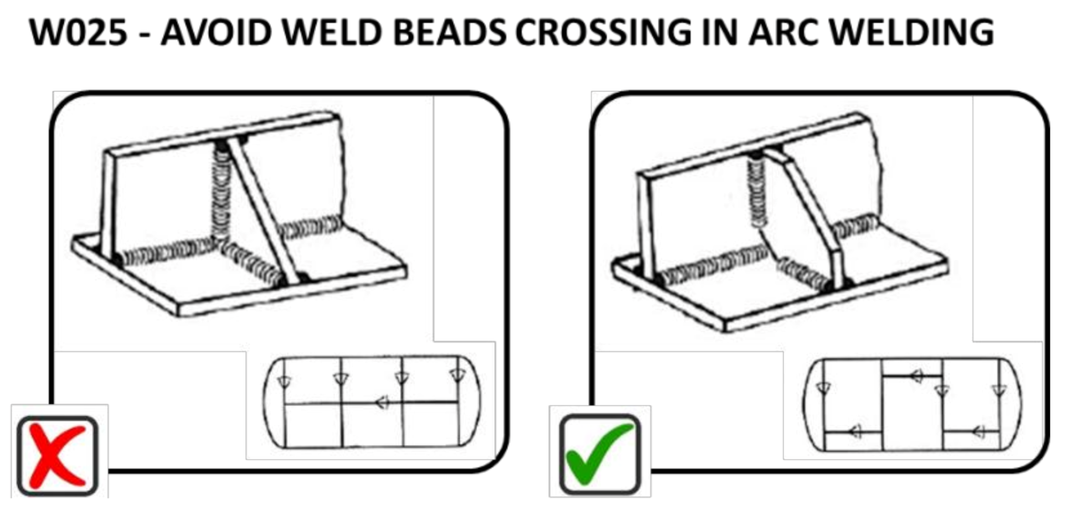
| W025 | Warning | Welding | N.A. | N.A. | All materials | N.A. | - Weld beads - Weld beads position | N.A. | Z = dimension of the weld beads D = weld beads distance | D ≥ 2,5 Z | Avoid weld beads crossing | [28] |
| W026 | Warning | Welding | N.A. | N.A. | All materials | N.A. | - Weld bead - Plates overlap - Plates thickness | N.A. | t1 = plate 1 thickness t2 = plate 2 thickness O = overlap length | O > 25 mm | Always guarantee a minimum overlap of 25 mm for overlapping welds | [46] |
| W027 | Warning | Welding | N.A. | N.A. | All materials | N.A. | - Weld bead - Weld bead dimensions - Plates thickness | N.A. | tp1 = plate 1 thickness tp2 = plate 2 thickness H = weld bead height | If tp1 or tp2 ≥ 20 mm, then tb ≥ tp1 and tp2 | Guarantee a complete joint penetration weld when plate higher than 20 mm | [46] |
| W028 | Warning | Welding | N.A. | N.A. | All materials | N.A. | - Weld bead - Weld bead dimensions - Plates thickness | N.A. | tp1 = plate 1 thickness tp2 = plate 2 thickness H = weld bead height W = weld bead width | H = f(tp1, tp2) W = f(tp1, tp2) | Guarantee the correct dimensions of weld bead in function of plates thickness | [46] |
| W029 | Warning | Welding | N.A. | N.A. | All materials | N.A. | - Weld bead - Weld bead dimensions | N.A. | L = weld bead length W = weld bead width H = weld bead height | L > 4 W L > 4 H | Guarantee the minimum weld bead length higher than 4 weld bead width or 4 weld bead height | [46] |
| W030 | Warning | Welding | N.A. | N.A. | All materials | N.A. | - Weld bead - Weld bead dimensions - Weld bead type - T joints - Plates thickness | N.A. | W = weld bead width H = weld bead height tp1 = plate 1 thickness tp2 = plate 2 thickness | W > t1, t2 H > t1, t2 | Guarantee the minimum weld bead dimensions higher than plate thickness in T-joints | [46] |
| W031 | Information | Welding | Arc welding | GMAW | Stainless steel | All stainless steels | - Weld bead | N.A. | N.A. | N.A. | Use a mixture of Ar/CO2/He as shielding gas for GMAW (MIG) welding of stainless steels | [46] |
| W032 | Information | Welding | Arc welding | GMAW | Aluminum alloy | All aluminum alloys | - Weld bead | N.A. | N.A. | N.A. | Use Argon (100%) as shielding gas for GMAW (MIG) welding of aluminum alloys | [47] |
| W033 | Information | Welding | Arc welding | GMAW | Carbon steels | All carbon steels | - Weld bead | N.A. | N.A. | N.A. | Use CO2 (100%) or a CO2/Argon (25–75%) mixture as a shielding gas for GMAW (MIG) welding of carbon steels | [47] |
| W034 | Warning | Welding | N.A. | N.A. | All materials | N.A. | - Weld bead - Weld bead dimensions | N.A. | L = weld bead length | If L > 800 mm, then intermittent welding | Use intermittent weld when welding length is higher than 800 mm | [48] |
| W035 | Warning | Welding | N.A. | N.A. | All materials | N.A. | - Weld bead - Neutral axis of the welded part | N.A. | D = distance between weld bead and Neutral axis of the welded part | D ≈ 0 | Position the welds near to the neutral axis of the welded part | [48] |
| W036 | Critical | Welding | N.A. | N.A. | Carbon steels | - Weld bead | N.A. | N.A. | Material elements: S ≤ 0,05%, P ≤ 0,06%, B ≤ 0,005%. | Check for the presence of chemical elements in the material of the welded parts (S, P, B) that have a bad effect on the quality of the weld | [48] | |
| W037 | Critical | Welding | Arc welding | GMAW | All materials | N.A. | - Weld bead - Weld joint overlap | N.A. | O = weld joint overlap | O > 12 mm | Guarantee a weld joint overlap higher than 12 mm in GMAW arc welding | [49] |
| W038 | Critical | Welding | Arc welding | GMAW | All materials | N.A. | - Weld bead - Slot weld - Plate thickness | N.A. | T = plate thickness L = slot length W = slot width X = distance between slot weld (short side W) Y = distance between slot weld (long side L) | W ≥ 3 T If 2 ≤ T < 3,1, then L = 25,4 mm If 3,1 ≤ T ≤ 4,6, then L = 31,8 X ≥ L Y ≥ 0,5 L + W | Guarantee the correct size and distance of the slots in the case of “slot welds” with GMAW arc welding | [49] |
| W039 | Warning | Welding | N.A. | N.A. | All materials | N.A. | - Weld bead - Butt welding - Curvature radius of plate in welding zone - Plate thickness | N.A. | R = curvature radius of plate in welding zone T = plate thickness | R ≤ 4 T | Guarantee a radius of the plate in butt welds zone not greater than to four times the plate thickness | [49] |
| W040 | Warning | Welding | Arc welding | GMAW | All materials | N.A. | - Weld bead - Plate curvature | N.A. | D = distance between the weld bead and the tangent to the radius of curvature of the plate | X > 10 mm | Guarantee a minimum distance of 10 mm between the weld bead and the tangent to the curvature radius of the plate in GMAW are welding | [49] |
| W041 | Critical | Welding | N.A. | N.A. | All materials | N.A. | - Weld bead - Structural welding | N.A. | Mc1 = material class of part 1 Mc2 = material class of part 2 | If Mc1 ≠ Mc2, then no structural welds | Avoid structural welds between components made with heterogeneous materials (not belonging to the same class) | Company practice |
| W042 | Information | Welding | N.A. | N.A. | All materials | N.A. | - Weld bead - Structural welding | N.A. | Mc1 = material class of part 1 Mt1 = material type of part 1 Mc2 = material class of part 2 Mt2 = material type of part 2 | If structural welds, then Mc1 = Mc2 and Mt1 = Mt2 | In case of structural welds prefer parts with the same material class and type | Company practice |
| W043 | Warning | Welding | N.A. | N.A. | All materials | N.A. | - Weld bead - Plate thickness | N.A. | Mc1 = material class of part 1 Mt1 = material type of part 1 Mc2 = material class of part 2 Mt2 = material type of part 2 t1 = plate 1 thickness t2 = plate 2 thickness | Mc1 = Mc2 Mt1 = Mt2 t1 = t2 | Use plates with the same materials and with the same thickness | Company practice |
| W044 | Warning | Welding | N.A. | N.A. | All materials | N.A. | - Weld bead - Light shapes dimensions | N.A. | Mc1 = material class of part 1 Mt1 = material type of part 1 Mc2 = material class of part 2 Mt2 = material type of part 2 W1 = light shape 1 width S1 = light shape 1 Section W2 = light shape 2 width S2 = light shape 2 section | Mc1 = Mc2 Mt1 = Mt2 W1 = W2 S1 = S2 | Use light profiles with the same materials, with the same widths and with the same sections | Company practice |
| W045 | Information | N.A. | N.A. | N.A. | All materials | N.A. | - Radius of pad edges (R) | N.A. | R = radius of pad edges | R ≠ 0 | Avoid sharp external corners in manipulated parts | [46] |
| W046 | Information | N.A. | N.A. | N.A. | All materials | N.A. | - Chamfer | N.A. | N.A. | N.A. | Avoid chamfer where not required in machining process | [46] |
References
- Pahl, G.; Beitz, W.; Feldhusen, J.; Grote, K.H. Engineering Design: A Systematic Approach, 3rd ed.; Springer: Berlin/Heidelberg, Germany, 2007. [Google Scholar]
- Ulrich, K.T.; Eppinger, S.D. Product Design and Development, 5th ed.; McGraw-Hill: New York, NY, USA, 2011. [Google Scholar]
- Morbidoni, A.; Favi, C.; Germani, M. CAD-Integrated LCA Tool: Comparison with dedicated LCA Software and Guidelines for the Improvement. In Glocalized Solutions for Sustainability in Manufacturing; Hesselbach, J., Herrmann, C., Eds.; Springer: Berlin/Heidelberg, Gemany, 2011; pp. 569–574. [Google Scholar]
- Marconi, M.; Germani, M.; Favi, C.; Raffaeli, R. CAD feature recognition as a means to prevent ergonomics issues during manual assembly tasks. Comput. Des. Appl. 2018, 15, 734–746. [Google Scholar] [CrossRef]
- Anderson, D.M. Design for Manufacturability: How to Use Concurrent Engineering to Rapidly Develop Low-Cost, High-Quality Products for Lean Production, 2nd ed.; Productivity Press: Boca Raton, FL, USA, 2020. [Google Scholar]
- Boothroyd, G.; Dewhurst, P.; Knight, W.A. Product Design for Manufacture and Assembly, 3rd ed.; CRC Press: Boca Raton, FL, USA, 2010. [Google Scholar]
- Chhim, P.; Chinnam, R.B.; Sadawi, N. Product design and manufacturing process based ontology for manufacturing knowledge reuse. J. Intell. Manuf. 2019, 30, 905–916. [Google Scholar] [CrossRef]
- Favi, C.; Germani, M.; Mandolini, M. Design for Manufacturing and Assembly vs. Design to Cost: Toward a Multi-objective Approach for Decision-making Strategies during Conceptual Design of Complex Products. Procedia CIRP 2016, 50, 275–280. [Google Scholar] [CrossRef][Green Version]
- Favi, C.; Campi, F.; Germani, M.; Mandolini, M. A data framework for environmental assessment of metal arc welding processes and welded structures during the design phase. Int. J. Adv. Manuf. Technol. 2019, 105, 967–993. [Google Scholar] [CrossRef]
- Favi, C.; Campi, F.; Germani, M. Comparative life cycle assessment of metal arc welding technologies by using engineering design documentation. Int. J. Life Cycle Assess. 2019, 24, 2140–2172. [Google Scholar] [CrossRef]
- Adamczyk, B.S.; Szejka, A.L.; Canciglieri, O. Knowledge-based expert system to support the semantic interoperability in smart manufacturing. Comput. Ind. 2020, 115, 103161. [Google Scholar] [CrossRef]
- Favi, C.; Campi, F.; Mandolini, M.; Germani, M. Using engineering documentation to create a data framework for life cycle inventory of welded structures. Procedia CIRP 2019, 80, 358–363. [Google Scholar] [CrossRef]
- La Rocca, G. Knowledge based engineering: Between AI and CAD. Review of a language based technology to support engineering design. Adv. Eng. Inform. 2012, 26, 159–179. [Google Scholar] [CrossRef]
- Lin, L.; Zhang, W.; Lou, Y.; Chu, C.; Cai, M. Developing manufacturing ontologies for knowledge reuse in distributed manufacturing environment. Int. J. Prod. Res. 2011, 49, 343–359. [Google Scholar] [CrossRef]
- Li, Z.; Zhou, X.; Wang, W.M.; Huang, G.; Tian, Z.; Huang, S. An ontology-based product design framework for manufacturability verification and knowledge reuse. Int. J. Adv. Manuf. Technol. 2018, 99, 2121–2135. [Google Scholar] [CrossRef]
- Mandolini, M.; Campi, F.; Favi, C.; Germani, M.; Raffaeli, R. A framework for analytical cost estimation of mechanical components based on manufacturing knowledge representation. Int. J. Adv. Manuf. Technol. 2020, 107, 1131–1151. [Google Scholar] [CrossRef]
- Reddy, E.J.; Sridhar, C.; Rangadu, V.P. Development of web-based knowledge-based system for CAD modeling and manufacturing. Mater. Today Proc. 2018, 5, 27241–27247. [Google Scholar] [CrossRef]
- Mikos, W.L.; Ferreira, J.C.E.; de Albuquerque Botura, P.E.; Freitas, L.S. A system for distributed sharing and reuse of design and manufacturing knowledge in the PFMEA domain using a description logics-based ontology. J. Manuf. Syst. 2011, 30, 133–143. [Google Scholar] [CrossRef]
- LeGoff, O.; Hascoët, J. From CAD to computer aided welding. Int. J. Prod. Res. 1998, 36, 417–436. [Google Scholar] [CrossRef]
- Kwon, Y.; Wu, T.; Saldivar, J.O. SMWA: A CAD-based Decision Support System for the Efficient Design of Welding. Concurr. Eng. 2004, 12, 295–304. [Google Scholar] [CrossRef]
- Maropoulos, P.G.; Yao, Z.; Bradley, H.D.; Paramor, K.Y.G. An integrated design and planning environment for welding Part 1: Product modelling. J. Mater. Process. Technol. 2000, 107, 3–8. [Google Scholar] [CrossRef]
- Um, J.; Stroud, I.A. Design guidelines for remote laser welding in automotive assembly lines. Int. J. Adv. Manuf. Technol. 2016, 89, 1039–1051. [Google Scholar] [CrossRef]
- Tasalloti, H.; Eskelinen, H.; Kah, P.; Martikainen, J. An integrated DFMA–PDM model for the design and analysis of challenging similar and dissimilar welds. Mater. Des. 2016, 89, 421–431. [Google Scholar] [CrossRef]
- Miller, S.W.; Finke, D.A.; Kupinski, M.; Ligetti, C.B. WeldANA: Welding decision support tool for conceptual design. J. Manuf. Syst. 2019, 51, 120–131. [Google Scholar] [CrossRef]
- Khosravani, M.R.; Nasiri, S.; Weinberg, K. Prediction of fracture in sandwich-structured composite joints using case-based reasoning approach. Procedia Struct. Integr. 2018, 13, 168–173. [Google Scholar] [CrossRef]
- Favi, C.; Campi, F. CAD-based design for welding (DFW) method. Int. J. Interact. Des. Manuf. (IJIDeM) 2020, 1–3. [Google Scholar] [CrossRef]
- Orlov, P. Foundamentals of Machine Design; Mir Publisher: Moscow, Russia, 1976; Volumes 1–4. [Google Scholar]
- Bralla, J.G. Design for Manufacturability Handbook, 2nd ed.; McGraw-Hill Companies: New York, NY, USA, 1999. [Google Scholar]
- Ciambrone, D. Effective Transition from Design to Production; Auerbach Publications: Danvers, MA, USA, 2007. [Google Scholar]
- Poli, C. Design for Manufacturing: A Structured Approach; Elsevier: Amsterdam, The Netherlands, 2001. [Google Scholar]
- Molloy, O.; Tilley, S.; Warman, E. Design for Manufacture and Assembly Concepts; Springer: Berlin/Heidelberg, Germany, 1998; pp. 1–21. [Google Scholar]
- El Wakil, S.D. Processes and Design for Manufacturing; CRC Press: Boca Raton, FL, USA, 2019. [Google Scholar]
- Radhakrishnan, V.M. Welding Technology and Design; New Age International Pvt Ltd.: New Delhi, India, 2011. [Google Scholar]
- Ashby, M.F.; Cebon, D. Materials selection in mechanical design. J. Phys. IV 1993, 3, C7-1–C7-9. [Google Scholar] [CrossRef]
- Sanfilippo, E.M.; Borgo, S. What are features? An ontology-based review of the literature. Comput. Des. 2016, 80, 9–18. [Google Scholar] [CrossRef]
- Fields, M.; Anderson, D. Fast feature extraction for machining applications. Comput. Des. 1994, 26, 803–813. [Google Scholar] [CrossRef]
- Sunil, V.; Agarwal, R.; Pande, S. An approach to recognize interacting features from B-Rep CAD models of prismatic machined parts using a hybrid (graph and rule based) technique. Comput. Ind. 2010, 61, 686–701. [Google Scholar] [CrossRef]
- Gao, J.; Zheng, D.; Gindy, N. Extraction of machining features for CAD/CAM integration. Int. J. Adv. Manuf. Technol. 2004, 24, 573–581. [Google Scholar] [CrossRef]
- Xuan, L.P.; Ngoc, L.T. Automatic Extraction and Welding Feature Recognition from STEP Data. In Computers and Devices for Communication; Springer: Berlin/Heidelberg, Germany, 2021; Volume 178, pp. 210–215. [Google Scholar]
- Kuss, A.; Dietz, T.; Ksensow, K.; Verl, A. Manufacturing Task Description for Robotic Welding and Automatic Feature Recognition on Product CAD Models. Procedia CIRP 2017, 60, 122–127. [Google Scholar] [CrossRef]
- Raffaeli, R.; Mandolini, M.; Germani, M. Identification of Weld Beads in Assemblies of B-Rep Models. Comput. Des. Appl. 2013, 11, 263–274. [Google Scholar] [CrossRef]
- Staub–French, S.; Fischer, M.; Kunz, J.; Ishii, K.; Paulson, B. A feature ontology to support construction cost estimating. Artif. Intell. Eng. Des. Anal. Manuf. 2003, 17, 133–154. [Google Scholar] [CrossRef]
- Machine Design—DFM for Welding. Available online: https://www.machinedesign.com/mechanical-motion-systems/article/21836735/dfm-for-welding?utm_campaign=Weekly+Newsletters&utm_source=hs_email&utm_medium=email&_hsenc=p2ANqtz-9VvvK2lnVpY5flcmgDhkMO4EIWAxUrvGsgG4wPupkDbVzRxUH8E2a4Pjk1XNq4tjxhz4B6 (accessed on 1 February 2021).
- DFMPro. Available online: https://dfmpro.com/ (accessed on 1 February 2021).
- ASM International Handbook Committee. ASM Handbook Volume 6, Welding, Brazing and Soldering, Welding of Nickel Alloys; ASM International: Mishawaka, IN, USA, 1993; ISBN 978-0871703828. [Google Scholar]
- AWS D1.1:2000-2. Welding Standard: Design of Welded Connections; American Welding Society: Miami, FL, USA, 2000. [Google Scholar]
- BERNARD. Available online: https://www.bernardwelds.com/7-tips-for-improving-mig-welding-p159576 (accessed on 1 February 2021).
- Axis Fabrication and Machine. Available online: https://axisfab.com/weld-shrinkage/ (accessed on 1 February 2021).
- Auto/Steel Partnership. GMAW Weld Design Guidelines for Chassis Structures; Final Project Report November 2007; Auto/Steel Partnership: Southfield, MI, USA, 2007. [Google Scholar]


| Rule # | Rule Type | Welding Technology | Material | CAD Features and Algorithms | Source | ||||||
|---|---|---|---|---|---|---|---|---|---|---|---|
| Class | Type—Level I | Type—Level II | Class | Type | CAD Features | PMI | Parameters | Rule | |||
| W025 | Warning | Fusion welding | Arc welding | N.A. | All materials | N.A. | - Weld beads - Weld beads position | N.A. | Z = dimension of the weld beads D = weld beads distance | D ≥ 2.5 Z | [28] |
| Component Model | Features |
|---|---|
 | ID: C001 Material: Carbon steel S235JR Mass: 1,73 kg Volume: 640425,668 mm3 Area: 269772,92 mm2 |
 | ID: C002 Material: Carbon steel S235JR Mass: 0,97 kg Volume: 360294,957 mm3 Area: 160737,86 mm2 |
 | ID: C003 Material: Carbon steel S235JR Mass: 0,39 kg Volume: 144026,440 mm3 Area: 75813,45 mm2 |
 | ID: C004 Material: Carbon steel S235JR Mass: 1,13 kg Volume: 145579,537 mm3 Area: 76034,60 mm2 |
 | ID: C005 Material: Carbon steel S235JR Mass: 0,71 kg Volume: 91091,139 mm3 Area: 62200,19 mm2 |
| Component Model | Features |
|---|---|
 | ID: G001 Type of feature: Sheet bend Coordinates of the feature in reference with origin: [127.77;0;0] (start point bend); [143,02;0;0] (end point bend) Volume: 145579,537 mm3 Area: 76034,60 mm2 FaceList:
|
 | ID: G002 Type of feature: Slot Coordinates of the feature in reference with origin: [136.89;0;0] Volume: 1553,097 mm3 Area: 593,10 mm2 FaceList:
|
| Component Model | Features |
|---|---|
 | ID: W001 Type of feature: Weld beam 01_Half sleeve vs. Base plate and Half sleeve vs. Top cross plate Coordinates of the welded parts involved in feature in reference with origin:
|
 | ID: W002 Type of feature: Weld beam 02_Web plate vs. Base plate and Web plate vs. Top cross plate Coordinates of the welded parts involved in feature in reference with origin:
|
 | ID: W003 Type of feature: Weld beam 03_Web plate vs. Half sleeve Coordinates of the welded parts involved in feature in reference with origin:
|
 | ID: W004 Type of feature: Weld beam 04_Web plate vs. Center tube (web plate geometric feature 03_slot) Coordinates of the welded parts involved in feature in reference with origin:
Properties of the feature:
|
| Component Model | Features |
|---|---|
 | ID: C001 Material: Carbon steel S235JR Mass: 152,01 kg Volume: 19363931,469 mm3 Area: 4396663,33 mm2 |
 | ID: C002 Material: Carbon steel S235JR Mass: 3,95 kg Volume: 503,755,732 mm3 Area: 78173.57 mm2 |
 | ID: C003 Material: Carbon steel S235JR Mass: 2,32 kg Volume: 295919,674 mm3 Area: 65700,52 mm2 |
 | ID: C004 Material: Carbon steel S235JR Mass: 0,58 kg Volume: 74100,000 mm3 (117325,000 mm3) Area: 27379,41 mm2 (28942,40 mm2) |
 | ID: C005 Material: Alluminum alloy 6061 Mass: 0,10 kg Volume: 38786,546 mm3 Area: 9254,80 mm2 |
 | ID: C006 Material: Alluminum alloy 6061 Mass: 0,18 kg Volume: 66646,643 mm3 Area: 15307,79 mm2 |
| Component Model | Features |
|---|---|
 | ID: W001 Type of feature: Weld beam 01_ HE 180 A vs. Plate 1 Coordinates of the welded parts involved in feature in reference with origin:
|
 | ID: W002 Type of feature: Weld beam 02_ HE 180 A vs. Plate 2 Coordinates of the welded parts involved in feature in reference with origin:
|
 | ID: W003 Type of feature: Weld beam 03_ HE 180 A vs. Plate 3 Coordinates of the welded parts involved in feature in reference with origin:
|
 | ID: W004 Type of feature: Weld beam 04_HE180 A vs. Crane eye Part 1 Coordinates of the welded parts involved in feature in reference with origin:
|
| Component Model | Features |
|---|---|
 | ID: W003_mod Type of feature: Weld beam 03_ HE 180 A vs. Plate 3_mod Coordinates of the welded parts involved in feature in reference with origin:
|
Publisher’s Note: MDPI stays neutral with regard to jurisdictional claims in published maps and institutional affiliations. |
© 2021 by the authors. Licensee MDPI, Basel, Switzerland. This article is an open access article distributed under the terms and conditions of the Creative Commons Attribution (CC BY) license (http://creativecommons.org/licenses/by/4.0/).
Share and Cite
Favi, C.; Garziera, R.; Campi, F. A Rule-Based System to Promote Design for Manufacturing and Assembly in the Development of Welded Structure: Method and Tool Proposition. Appl. Sci. 2021, 11, 2326. https://doi.org/10.3390/app11052326
Favi C, Garziera R, Campi F. A Rule-Based System to Promote Design for Manufacturing and Assembly in the Development of Welded Structure: Method and Tool Proposition. Applied Sciences. 2021; 11(5):2326. https://doi.org/10.3390/app11052326
Chicago/Turabian StyleFavi, Claudio, Roberto Garziera, and Federico Campi. 2021. "A Rule-Based System to Promote Design for Manufacturing and Assembly in the Development of Welded Structure: Method and Tool Proposition" Applied Sciences 11, no. 5: 2326. https://doi.org/10.3390/app11052326
APA StyleFavi, C., Garziera, R., & Campi, F. (2021). A Rule-Based System to Promote Design for Manufacturing and Assembly in the Development of Welded Structure: Method and Tool Proposition. Applied Sciences, 11(5), 2326. https://doi.org/10.3390/app11052326