Abstract
This article presents a gradient-based aerodynamic optimization framework and investigates optimum deformations for a transonic airfoil equipped with morphing leading and trailing edges. Specifically, the proposed optimization framework integrates an innovative morphing shape parameterization with a high fidelity Reynolds-averaged Navier–Stokes computational fluid dynamic solver, a hybrid mesh deformation algorithm, and an efficient gradient evaluation method based on continuous adjoint implementation. To achieve a feasible morphing shape, some structural properties of skin and wing-box constraints were introduced into the morphing shape parameterization, which offers skin length control and enables wing-box shape invariance. In this study, the optimum leading and trailing edge deformations with minimization of drag at this cruise stage were searched for using the adjoint-based optimization with a nested feasible morphing procedure, subject to the wing-box, skin length, and airfoil volume constraints. The numerical studies verified the effectiveness of the optimization strategy, and demonstrated the significant aerodynamic performance improvement achieved by using the morphing devices. A lambda shock pattern was observed for the optimized morphing leading edge. That result further indicates the importance of leading edge radius control.
1. Introduction
With ever-increasing international awareness of economic efficiency and environmental protection, a more efficient aircraft design that reduces fuel consumption is urgent. The morphing technology developed in recent decades aims at addressing this issue through increasing efficiency during cruising, or better yet, during off-design points by adapting the wing shape or dedicated control surfaces. To date, most studies have focused on implementing the morphing technology by retrofitting the existing aircraft configurations by implementing new dedicated devices, such as leading and trailing edge morphing [1,2,3,4,5].
Aerodynamic optimization is an essential part in the definition of morphing shape. Fincham and Firswell [6] established an airfoil camber morphing optimization framework with Genetic Algorithms (GAs), in which the XFOIL solver based on potential flow theory with boundary layer correction was adopted. They used a third-order polynomial to accurately represent the camber-line deformation of the airfoil embedded with the Fish Bone Active Camber (FishBAC) system. In [7], the aerodynamic benefits of transport airfoil with morphing trailing edge wings were quantified by a gradient-based optimization optimizer coupled with a high-fidelity computational fluid dynamic (CFD) solver. The wing is parameterized by the free form deformation (FFD) method. The FFD control points near the trailing edge can move independently in the vertical direction to simulate the small perturbations of the morphing trailing edge. However, vertical deformation of the trailing edge increases or decreases skin length, resulting in additional axial stress that is necessary to avoid. Generally, a morphing device consists of actuators, internal mechanisms, and skin, and it is designed to deform in a prescribed manner. Incorporating of the structural requirements in the aerodynamic optimization of morphing airfoil appears as beneficial to guarantee a good compromise between the aerodynamic performance and the energy requested to deform the structure, mainly the skin. Indeed, even during an aerodynamic optimization to define an optimal morphing shape when the internal structure does not exist, the skin’s structural behaviors should be considered to obtain a feasible morphing shape that is not excessively deformed and at the same time easily controlled by the actuation and internal structure [3,8].
One possible approach to defining a feasible morphing shape is by evaluating the existing internal mechanisms. For the active trailing edge device reported in [9], the airfoil surface comprises rigid and flexible regions and is driven by three rotation inputs. Bézier curves controlled by four points at each flexible region are employed to represent the discrete kinematic model. Inspired by the conventional drop nose device, Suzuki et al. [10] established leading edge deformation by imposing a rigid rotation first and smoothing the curve by variation of the camber line and thickness distribution. A fourth-order polynomial term of the camber line and thickness is used, and a total of 10 coefficients is needed. Kan and Li et al. [11] used a parabolic function to deform the front quarter chord of the airfoil, and examined the unsteady aerodynamic characteristics.
Other researchers discovered the potential of the existing class/shape transformation (CST) parameterization method in pursuing the development of a general morphing airfoil shape. As a result, the existence of specific morphing devices is unnecessary. CST parameterization was initially developed by Kulfan [12] and proved to be one of the best candidates for parameterization under the criteria of completeness, flawlessness, intuitiveness, orthogonality, and parsimony [13], thereby improve smoothness when involving machining [14,15]. Magrini et al. [16] provided a procedure to maintain the skin length to minimize the axial stress. Specifically, an iterative optimization algorithm automatically adjusts two additional coefficients (one for each upper or lower surface) to keep the skin length of the new airfoil equal to that of initial airfoil. Based on the observation of existing morphing airfoils, some authors suggested varying the chord length during morphing. Leal et al. [17] proposed a modified CST method in order to maintain structural consistency, based on the morphing structural assumptions of compliant ribs, rigid spar, constant leading edge radius, and passive surface length. The chord length is adopted as the parameter, and the constant length of the passive surface assumption is satisfied by solving a fixed-point iteration problem. De Gaspari et al. [18] developed a knowledge-based skin structural (KBSS) feedback method considering the wing-box, airfoil area, skin length, and curvature constraints, and performed morphing wing shape optimization using GAs.
Such parameterization, which considers the general characteristics of the morphing airfoil without considering specific morphing mechanisms, is beneficial for the morphing aerodynamic shape optimization. However, current optimizations based on feasible morphing shape parameterization are solved by GAs, which requires an enormous evaluation of the aerodynamic responses that are time-consuming when a high fidelity CFD solver is involved. With the rapid development of a CFD adjoint solver, gradient optimization has the potential to be an affordable tool for resolving the problem mentioned above. In each optimization iteration, the computation requires solving one flow and several adjoint problems depending on the number of functions to be evaluated. Consequently, the computational time of evaluating the sensitivities is independent of the number of the design variables.
In this paper, we focus on the aerodynamic shape optimization with a parameterization dedicated to the morphing, particularly for two-dimensional morphing airfoil design. A gradient-based morphing shape optimization framework is presented that uses a Reynolds-averaged Navier–Stokes (RANS) CFD solver, an advanced adjoint implementation, a robust mesh deformation algorithm, and an innovate shape parameterization method. In this method, the shape of the morphing system is implicitly represented by the parameterization that not only keeps the shape invariant in the wing-box region but also provides skin length control. Using this framework, an optimization example that minimized the drag by morphing the leading and trailing edges was carried out, and the potential of drag reduction was investigated.
The paper is organized as follows: the feasible morphing airfoil geometry parameterization and the optimization framework are detailed described in Section 2; then, in Section 3, the presented method is applied on a transonic airfoil to increase the performance by minimizing the drag coefficient at cruise; finally, the conclusions are summarized in Section 4.
2. Methodologies
2.1. Optimization Framework
The aerodynamic shape optimization framework is illustrated in Figure 1, which includes a CST-based morphing airfoil parameterization, a mesh deformation tool, a flow and adjoint solver, and a gradient-based optimizer. For each iteration, the optimizer invokes each component sequentially if necessary. The baseline airfoil is initially prepared as a mesh file, and the corresponding shape is identified by the shape parameterization method as a vector of design variables. Then, the optimizer launches the primary flow solver and adjoint solver successively, in order to evaluate the objective function and obtain the sensitivities with respect to the surface mesh. The obtained surface sensitivities are then projected into design space through geometric sensitivities (also known as design velocities). The optimizer drives the optimization loop, finds new design variables, deforms the mesh, and evaluates the new shape.
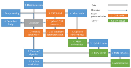
Figure 1.
Optimization framework.
2.2. Feasible Morphing Airfoil Geometry Parameterization
The generalized CST equations are presented first, aiming at offering a matrix formulation. Local shape deformation, a smooth contour, skin length restraints, and an airfoil volume constraint are considered as the basic characteristics of a feasible morphing shape parameterization. The choice of keeping a constant arc length for the passive skin is intuitive, and this was done to minimize the axial stress in the skin and eliminate the skin buckling when being compressed.
2.2.1. Generalized CST Equations
The CST method, a fundamental parametric airfoil geometry parameterization method [12], consists of a class function , a shape function , and a pair of boundary conditions at leading and trailing edges [18]. The geometric parameters describing the CST airfoil are shown in Figure 2 This method maps the non-dimensional coordinate , which is the chord-wise axis of the Cartesian coordinate system, to vertical ordinate :
where the subscript and represent trailing edge and leading edge, respectively.
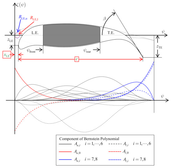
Figure 2.
The geometric parameters describing the class/shape transformation (CST) airfoil and the corresponding Bernstein polynomial of the baseline shape. is the dimensional radius of leading edge curvature, the subscripts and represent upper and lower surfaces. and are the vertical positions of leading and trailing edge points. and are chord-wise positions. is the trailing edge’s boat-tail angle. A is the coefficient that scales each corresponding Bernstein polynomial.
The class function , a single-lope curve, is a term that includes two parameters, and . Various general shapes, such as airfoil and aircraft body cross-sectional shape, can be represented by adjusting those two parameters [12]. For example, by setting and , a round leading and sharp (or blunt) trailing edge subsonic airfoil can be defined. In this paper, and are default parameters. The expression of class function is:
The geometry is further modified by introducing the shape function , which is composed of Bernstein polynomials to order n, and coefficients that adjust and scale each polynomial. The shape function can be expressed in a compact form:
where is the binomial coefficient, is a column vector of coefficients, and consists of Bernstein polynomials.
Furthermore, a pair of boundary conditions for leading and trailing edges is added to release the vertical displacement freedom, thereby enabling the ability of representing the movement of the morphing leading and trailing edges physically:
where and are the non-dimensional vertical positions of leading and trailing edge points, respectively. Both of them are non-dimensionalized by the chord from dimensional and . is the thickness of the trailing edge tip. For those airfoils with sharp trailing edges, .
Consequently, the upper and lower surfaces of an airfoil are:
where the subscript and represent the upper and lower surfaces of an airfoil, respectively.
The first and the last Bernstein polynomials’ coefficients have a physical interpretation. The first term is relevant to the radius of curvature of the leading edge, whilst the last, , can be formulated from the trailing edge boat-tail angle , and both the vertical location of leading and trailing edge. Those properties enable the intuitiveness of the CST parameterization method and are beneficial to establish the morphing leading and trailing edge functionality that will be shown in the following sections.
where is the dimensional radius of leading edge curvature; and are first and second derivatives of CST formulation with respect to non-dimensional coordinate , respectively.
2.2.2. CST Coefficient Identification
The parameterization procedure starts with the identification of the Bernstein polynomials’ coefficients for both lower and upper surfaces, which can be evaluated by various techniques, e.g., curve fitting, and gradient-based and genetic optimization [17], to minimize the error from the CST airfoil representation and the already available one that is represented by points or as a CAD file. In this work, curve fitting is employed, and a least-square solution is obtained by solving an over-determined linear system.
The identification of the CST parameters consists of projecting the existing airfoil into CST space. Most of the airfoils are represented by the coordinates of points. The airfoil is first translated by putting the leading edge point on the vertical axis of the current coordinate system. Then the dimensional coordinates of an input airfoil are non-dimensionalized by chord length. This procedure is a bijective transformation from domain where to domain where by setting .
After transformation of the coordinates, denote as distinct points with a total number of l, such that , depicts the coordinates of a set of points on the upper or lower surface of an input airfoil. Generally, the order of polynomials is less than the number of points, i.e., . The coefficient identification problem is to find a suitable set of that minimizes the sum of the square of deviations from the data to , i.e., , which is equivalent to solve the over-determined linear system [18]:
where
is a Bernstein–Vandermonde matrix [19] with a size of , and
2.2.3. Morphing Leading and Trailing Edge Algorithm
Many of the the morphing concepts applied to transport aircraft are now trying to improve existing aircraft by retrofitting the leading edge [20], the trailing edge [21,22], or the upper surface [23], without changing the main bearing structure [24]. This can be explained from both an aerodynamic and a structural point of view. On the one hand, the aerodynamic performance is more sensitive to the geometric variation at the leading and trailing edges. The stagnation point, where the local velocity turns to zero and the static pressure shows the highest value, is located at the leading edge. Additionally, when the airfoil approaches the stall angle, the separation of flow starts on the upper surface of the leading edge. Besides, the laminar-to-turbulent flow transition point and the shock wave are located on the upper surface [25]. On the other hand, the wing-box of a fix-wing aircraft is the primary load-carrying structure. Designers intend to introduce the morphing system while keeping the overall static and dynamic performance of structure [26].
The distinction between standard aerodynamic shape optimization and morphing airfoil optimization is obvious. In the morphing airfoil optimization, the morphing structure designed to form morphing shape should be considered during the shape optimization. In the preliminary morphing optimization framework, the feasible morphing should be defined based on certain morphing mechanisms, or at least the behavior of the skin that is part of the morphing mechanisms. The skin length is also useful in representing the kinematics of a morphing skin. For the passive non-stretched skin, the skin length should maintain a constant value. For those actuated surfaces, morphing skin coupled with a sliding system and the advanced flexible morphing skin [27], the variation of skin length can be released to a particular value [8].
This paper adopts a feasible morphing airfoil parameterization method aimed at providing local deformation, skin length control, and in the meantime maintaining invariance of wing-box region. The feasible morphing airfoil generation algorithm based on the CST parameterization method is shown in Figure 3, including an inverse fitting and a single-value optimization problem. The former guarantees the generated airfoil satisfying the wing-box constraint, and the latter provides length control of the skin. Here, the parameters in the CST airfoil parameterization method are divided into three categories based on the aerodynamic performance index, skin length constraint, and wing-box constraint.

Figure 3.
Morphing algorithm for maintaining the wing-box and the length of the skin.
For example, consider an airfoil shown in Figure 2. The chord-wise position plays a key role in keeping the constant skin length when leading edge is morphing. In addition, design variables driven by the aerodynamic optimizer are the leading edge radii of upper and lower skin (, ), vertical position (), and a zero or one CST coefficient that peaks near the front spar ( and ). Regarding the trailing edge morphing, the chord length is determined in order to provide skin length control. The parameters exposed to the aerodynamic optimization problem are the boat-tail angle , vertical position of trailing edge, and several CST coefficients with peaks located in the trailing edge ( and for ). In the nested single value optimization problem, a convergence tolerance of is adopted.
The remaining CST coefficients are obtained by solving the inverse fitting problem Equation (7) so that the curves always attach the wing-box. Let be the points in the subset space of airfoil , where subscript stands for box. The morphing part of airfoil is indicated by subscript . In other words, the chord-wise coordinate of distinct points is located from to , where and represent front and rear spars of the wing-box. Those locations of wing-box points are known to the designer as morphing always starting from a baseline airfoil. Meanwhile, the coefficient vector is partitioned into , in which the subsets and represent box and perturbed aerodynamically driven terms, respectively. Consequently, the inverse fitting problem to solve is adjusted to
The coefficients with regard to the wing-box constraints are solved by evaluating the first row:
An example of a deformed RAE 2822 airfoil is shown in Figure 4. In this case, the morphing shape is obtained in a sequential way. Firstly, the intermediate airfoil with a morphing trailing edge is generated by changing the morphing trailing edge aerodynamic design parameters and taking the baseline airfoil as a reference with wing-box of . The length of upper skin is kept constant through solving a nested single value optimization problem. As a result, the chord length slightly decreases. Then, the obtained intermediate airfoil with morphing trailing edge is taken as the reference airfoil, and the leading edge morphing is achieved by perturbing the leading edge aerodynamic design variables. Now, the wing-box region is , and the wing-box constraint is preserved by re-evaluating the subset of CST coefficients by solving an inverse fitting problem. Meanwhile, the chord-wise coordinate of leading edge point varies to keep the length of leading edge skin constant.
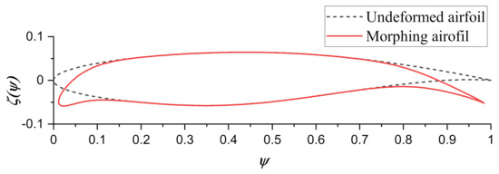
Figure 4.
RAE 2822 with morphing leading and trailing edges.
2.3. Mesh Deformation
A hybrid mesh deformation strategy, which consists of the deformation of the surface mesh by a radial basis function (RBF) tool and the deformation of the surrounding volume mesh by linear elasticity formulation, is adopted in this work. The first stage is surface mesh deformation. However, the mesh mapping from the baseline CST airfoil to the morphed CST airfoil is not straightforward, since the mesh grid points and the CST airfoil may not always coincide with each other. An auxiliary function is required for surface mesh mapping, and the idea is to construct an RBF interpolation of the displacement on a set of boundary nodes.
Assume we have the undeformed baseline CST airfoil , and the corresponding the morphed CST airfoil . There are points with coordinates on the corresponding undeformed surface mesh, where is the set of surface mesh nodes indexes on the surface to be designed. Meanwhile, the corresponding mesh point coordinates on the deformed surface are . The surface mesh mapping problem is, given the baseline CST airfoil and the corresponding morphed CST airfoil , computing a mapping function such that the surface mesh nodes on the morphed surface can be found through a linear mapping .
The mapping function is constructed from the pair of points from baseline CST airfoil to morphed CST airfoil . There are two sets of points: on the , and on , where is the space such that point and share the same arc length measured from the origin (i.e., leading edge point).
For convenience, two displacement fields from baseline CST airfoil and surface mesh nodes on to morphed CST airfoil and surface mesh nodes are introduced:
The displacement interpolation space can be generated from the generic RBF with first-order polynomial correction [28]:
where, s is a scalar value, weighed by coefficient is the non-negative radial interaction function defined on the positive real axis, is evaluation point, and are source points that also be called centers with a total number of source points of N. Here, in the displacement interpolation problem, the source points are . A first-order polynomial h is usually added for resolving the ill condition of the interpolation matrix. In a two-dimensional space, the linear polynomial has the form of , where denotes the Euclidean distance, which is the standard metric to represent the straight-line distance. The radial basis fitting exists if the weights and the coefficients of the polynomials correction can be evaluated such that the desired values are obtained at source points:
and also have to satisfy the orthogonality conditions as:
After collecting the desired values in vector , the above radial basis fitting problem can be formulated in a linear system:
where is the interpolation matrix defined as
and is a constraint matrix that consists of the first-order polynomial terms at the positions of source points.
The coefficient vector and can be solved as follows:
where .
Now the scalar value at arbitrary points can be evaluated by right-multiplying coefficient vector and by an interpolation recover matrix , which takes the form
In a compact form, it yields
where .
In this paper, the Wendland C4 function is selected as the kernel of RBF [29]:
where is chosen based on the maximum distance between two adjacent mesh nodes such that .
The displacement field can be interpolated through vector v by right-multiplying matrix . Subsequently, the coordinates on the deformed surface mesh can be resolved by .
In the second stage, the volume mesh is morphed using the equation of linear elasticity [30]. The new coordinates of the surface nodes are imported as an external file. The linear elasticity mesh deformation shows the efficiency and robustness, and can keep the topology of the volume mesh. When a large mesh deformation is required, the input displacements are divided into several sub-load steps, and the linear elastic problem is solved subsequently. In order to preserve the high resolution of the boundary layer of the volume mesh while propagating the mesh deformation, Young’s modulus of each mesh cell is set as inversely proportional to the cell volume. In other words, the smaller the cell volume, the larger the modulus, and vise versa.
The mesh deformation algorithm is summarized below:
- The construction of the RBF interpolation matrix by using the points on baseline CST airfoil and the mesh points on the corresponding undeformed surface ;
- The generation of the displacement field by evaluating , in which on the morphed CST airfoil, sharing the same normalized arc length with the ;
- The projection of displacement field from CST airfoil surface to surface mesh through matrix , yielding , then mesh points on the morphed surface are finally obtained;
- The propagation of the displacement on the surface to the entire volume mesh through solving the linear elastic deformation problem.
The application of the mesh deformation algorithm to an airfoil with morphing leading and trailing edges is demonstrated in Figure 5. The presented method proved to be efficient and robust in the preliminary test, and can be naturally extended to aero-structural coupling when the internal morphing mechanisms are available. However, the only flaw in this method is the negative effects on the orthogonality of the boundary layer mesh. The authors have compared the result calculated on the deformed mesh with the one obtained from the rebuilt mesh, and the deviation on the drag is acceptable.
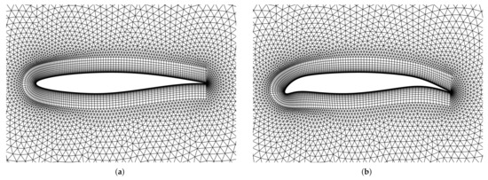
Figure 5.
Mesh deformations of airfoil with morphing leading and trailing edges. (a) Undeformed RAE 2822 mesh. (b) Morphing RAE 2822 mesh.
2.4. Flow and Adjoint Solver
Both flow and adjoint problems are solved in SU2 (Version 6.20), an open-source CFD solver based on a finite volume method (FVM) formulation [31]. Compressible RANS equations govern the flow around the airfoil, and the turbulence model adopted to close the RANS equation is the Spalart–Allmaras (S–A) one-equation model [32].
Two adjoint approaches, the continuous [33] and discrete approach, have been implemented in SU2 [34]. The former is a problem-based solver by evaluating adjoint through boundary surface integral with the frozen turbulent viscosity assumptions; the latter is a pure code-based adjoint solver by implementing algorithmic differentiation. Readers interested in those adjoint approaches for CFD can refer to [35]. In this paper, the sensitivity is provided by continuous adjoint method.
For numerical settings of the flow and adjoint solver, the Jameson–Schmidt–Turkel (JST) non-conservative central scheme is adapted for the discretization of both the flow and adjoint convective fluxes. A Venkatakrishnan slope limiter is used with a coefficient of . The spatial gradient of the flow and adjoint is approximated by means of the Green–Gauss approach. An implicit Euler scheme is used for integration, and the flexible generalized minimum residual (FGMRES) linear solver with incomplete lower upper factorization (ILU) linear preconditioner was chosen.
2.5. Gradient Evaluation
The gradient with respect to the morphing airfoil design variables is obtained through sensitivities vector right multiplying by the geometric sensitivities. The geometric sensitivities matrix establishes the link between the morphing airfoil design variables and the movement of mesh nodes on the surface to be designed. For the morphing leading edge, the design variables are leading edge vertical position , leading edge radius , and extra CST weighting coefficients on each surface. For the morphing trailing airfoil, the design variables are trailing edge vertical position , boat tail angle , and extra subset of CST weighting coefficients with a total number of . In general, the design variables can be written in a general and compact form .
Assume applying an infinitesimal perturbation of a design variable ; the gradient of the function of interest f can be established by evaluating the surface integral on the surface being designed [36]:
where is the index set of mesh nodes on the surface to be designed, is the surface sensitivity at the mesh node with index , is the area (length for 2D flow) of the control volume that surrounds node i, is unit normal vector, and is the displacement of node i after introducing the infinitesimal perturbation of design variable . In this paper, the products of surface sensitivities and s are called sensitivities. Note that for the continuous adjoint solver, the normal direction points to inside the airfoil; hence, a positive surface sensitivity indicates that an inward perturbation of the surface leads to an increment of the objective function. However, the definition of sign convention in geometric sensitivity is the opposite to that of surface sensitivity. Hence, a minus sign is required in Equation (21).
Moreover, the displacement is obtained through finite-difference by employing small perturbations for the design variable . The computational cost of generating the geometric sensitivities is negligible compared with the flow solver.
Consequently, the gradient evaluation in this optimization framework yields
3. Results and Discussion
The optimization framework described in the preceding section was applied to RAE 2822 airfoil in transonic, viscous flow, aiming at minimizing the drag for cruising at a constant lift coefficient of . The free-stream Mach number was , and the Reynolds number was . For the constraints, the maximum allowable volume variation was adapted by introducing an inflatable term to control the shape deformation space and prevent unrealistic morphing shapes in the meantime. The general optimization problem is presented as follows:
where indicates the wing-box region, is the volume of baseline airfoil, and is the variation of volume after morphing. The last three constraints introduce the skin length control, where and limit the skin length of the entire leading edge and the upper skin of the trailing edge, respectively. While the lower skin length of trailing edge is allowed to lengthen or shorten about of the chord, this can be achieved by the presence of specific sliding systems, hyper-elastic material, or lattice structure.
An O-type-mesh adapted from the SU2 test cases is used in this paper with a distance to the far-field of 100 chord lengths. The hybrid mesh for the current simulation is created with structural quadrilateral mesh near the airfoil, where 108 points are distributed along the upper surface and 85 points along the lower surface with a total number of 192, and an unstructured triangular grid in the other field with total 22,842 cells. The initial wall-normal grid points are located at for a chord length, the corresponding in wall units.
The baseline airfoil was first simulated on the compressible RANS with the S–A turbulence model. The flow solver automatically used a simple trim algorithm by adjusting the angle of attack (AoA) to achieve the target lift coefficient. The drag coefficient of the baseline airfoil is counts (1 count = ), and the corresponding AoA is degrees.
The RAE 2822 airfoil was then identified and projected from coordinates to CST design space, by means of the CST coefficient identification method with Bernstein polynomial order of 10.
The optimizations were performed using the gradient-based fmincon from MATLAB by choosing the active-set algorithm, which uses a sequential quadratic programming (SQP) technology and solves a quadratic programming (QP) sub-problem at each major iteration. The optimizer updates the Hessian matrix at each iteration utilizing the Broyden–Fletcher–Goldfarb–Shanno (BFGS) formula and then carries out a line search. A maximum line search step length of was employed to control the magnitude of the design variables and avoid non-physical deformation of the airfoil. The optimization was terminated when the stopping criteria (step or function changing is less than tolerance of ) were satisfied, or the maximum iteration limit of 50 was reached.
In the following subsections, the gradient verification is shown first. Subsequently, three optimization cases are shown: morphing only the leading edge, then the trailing edge, and finally, the leading and trailing edges.
3.1. Sensitivities Verification
The gradients obtained with the method provided in this paper are compared with those computed with forward-difference. Different finite-difference steps have been tested, while decreasing from a step size of of chord length until the finite-difference gradients converged. In the results shown in this subsection, the reference gradients were computed using a finite-difference step size of .
Surface sensitivities, which are the variations of the objective function with respect to the infinitesimal deformation along the normal direction of surface nodes, are projected to the feasible morphing airfoil geometry parameterization design space through the geometric sensitivities matrix to obtain gradients.
Before demonstrating the gradients, it is worthwhile showing the geometric sensitivities projection matrix. Geometric sensitivities, also known as design velocities, are computed through forward finite differences. A step of was used. The preliminary test indicates that the geometric sensitivities are insensitive to the size of the finite difference step.
Figure 6 provides the geometric sensitivities for an airfoil of which wing-box locating with respect to , and for leading edge morphing, , and two extra CST coefficients and on upper and lower surface for the trailing edge morphing. Note that arrows with outward displacement on the airfoil indicate positive geometric sensitivities, negative for inward. A scale factor has been applied to the magnitude of each geometric sensitivity for a better illustration. Theoretically, the morphing leading and trailing edge algorithm ensures the perturbation appears only in the design region. However, a small error is observed in the non-morphing domain. This error is due to the residual that is introduced in solving the over-determined equation. The magnitude of residual is times smaller than the required value of geometric sensitivity, which is considered as acceptable.
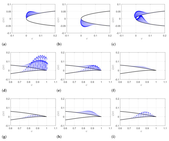
Figure 6.
Geometric sensitivities of morphing leading and trailing edges. Geometric sensitivities of morphing leading edge with respect to , , and , whose amplitudes have been multiplied by a factor of 20 for better demonstration. The amplitude of has been multiplied by a factor of 10, and the magnitudes of , , , , and have been multiplied by a factor of 100. (a) . (b) . (c) . (d) . (e) . (f) . (g) . (h) . (i) .
The geometric sensitivities at the morphing leading edge region shown in Figure 6a–c have the same order of magnitude. On the contrary, the magnitudes of geometric sensitivities for the morphing trailing edge, from Figure 6d–i, show inconformity. The impact of is 200 to 300 times larger than other parameters. This result suggests that gradients are highly sensitive to the vertical displacement of the trailing edge, which may amplify the error of adjoint results.
The sensitivities on the surface nodes provided by continuous adjoint and gradients comparison are displayed in Figure 7. It is not surprising that a discontinuity of sensitivity at the tip of the trailing edge on the upper surface is present, as shown in Figure 7a, which leads to the gradient inaccuracy at the gradient concerning the design variable for trailing edge morphing. Several authors [34,37] also observed this phenomenon, mainly due to the assumption of smooth surface in continuous adjoint method and the presence of the sharp trailing in this case. Readers who are interested this problem are prompted to refer to [33,38] for details.
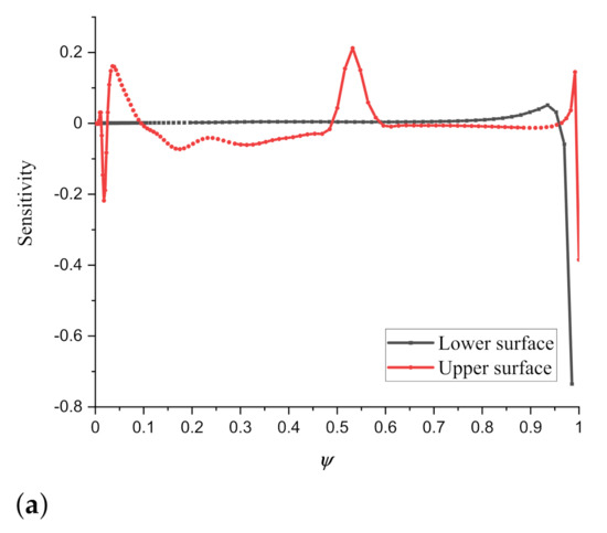
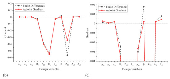
Figure 7.
Adjoint surface sensitivity and a comparison of the projected gradient with results obtained from finite difference on RAE 2822 with drag as the objective function. (a) Surface sensitivity. (b) Gradient. (c) A zoom of gradient.
Fortunately, except for discrepancies for design variables at the trailing edge, no significant problem has been found. The gradients with respect to the design variables of leading edge show good agreement with the results from finite differences. Although the numerically exact gradient information was not obtained, the gradients still can provide sufficient accuracy and lead the optimizer to find optimized results.
3.2. Minimization of Drag by Morphing Leading Edge
The first case involves the optimization shape design of morphing leading edge (mLE) to improve the aerodynamic performance in the cruise stage in terms of drag coefficient at a constant lift coefficient. The wing-box region starts from 10% of the chord to trailing edge, ensuring the morphing only occurs in the front 10% of the airfoil. In this case, the aerodynamic design variables are vertical position and the upper and lower skin radius of the leading edge. Chord-wise position of leading edge point and the remaining subset of CST coefficients are automatically determined through the morphing algorithm proposed in Section 2.2.3.
Optimization starts from baseline airfoil and obtains the optimal solution after 10 major iterations. Optimization runs in parallel on a hexagon-core processor with frequency GHz. It costs around 20 min for one iteration, including solving both flow and adjoint problem. The optimizer may invoke the flow solver several times between each iteration to evaluate the objective function with new design variables. The convergence history is presented in Figure 8a. The drag coefficient converges to counts, with drag reduction, while keeping a constant lift coefficient by adjusting the angle of attack from the initial degrees to degrees. An aerodynamic efficiency improvement of is achieved by evaluating the change of lift to drag ratio. The vertical displacement varies from 0 to , and the corresponding deflection is degrees. The upper surface leading edge radius of the optimized airfoil is around times that in the baseline airfoil, varying from to . The lower skin leading edge radius of optimized airfoil decreases from to . Figure 8c compares the optimized mLE shape with the baseline airfoil. Increment of leading edge radius on the upper skin leads to a flatter upper leading edge surface.
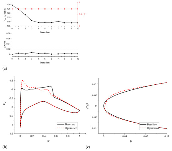
Figure 8.
Comparison of results for the RAE 2822 optimization using a morphing leading edge. (a) Convergence history. (b) distribution. (c) Airfoil shape.
A comparison of the Mach contour for both baseline and optimized airfoil with mLE is displayed in Figure 9; the strong shock wave at around is eliminated and replaced by a smoother shock wave recovery. In the meanwhile, the strongest shock wave appears near the leading edge. Those phenomena in the Mach contour also affect the pressure coefficient distribution in Figure 8b. A stronger sucking force is generated in the leading edge, and the pressure gradient at half chord is alleviated. The pitching moment increases consequently.
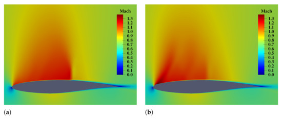
Figure 9.
Mach contours for baseline and optimized RAE 2822 by using a morphing leading edge. (a) Baseline airfoil. (b) Optimized airfoil with a morphing leading edge.
3.3. Minimization of Drag by Morphing Trailing Edge
The second application minimizes drag coefficient using a morphing trailing edge (mTE) locating at rear 30% of the chord. Design variables are vertical position, boat tail angle of the trailing edge and two extra CST coefficients.
The same as the mLE case, we start the optimization from baseline airfoil. An optimized solution is obtained after 21 major iterations, which shows more difficulty finding optimal design than the previous case. The drag coefficient decreases to counts, with a drag reduction. The AoA in the optimized airfoil changes to degrees to keep a lift coefficient of .
Figure 10 provides the comparisons of pressure coefficient distribution and the shape between baseline and optimized airfoil. The boat tail angle of the optimized mTE is degrees, 2 times of which at baseline airfoil. Consequently, increased camber near the trailing edge is achieved. A higher pressure difference between upper and lower at the trailing edge surface is observed, as shown in Figure 10a. A smaller angle of attack results in a lower pressure difference in the leading edge region. The shock wave and the resulting pressure discontinuity slightly moves from to of the chord length, and a gentler pressure drop after the shock wave is achieved.
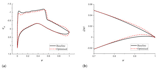
Figure 10.
Comparison of results for the RAE 2822 optimization using a morphing trailing edge. (a) distribution. (b) Airfoil shape.
3.4. Minimization of Drag by Morphing Both Leading and Trailing Edge
Our goal in this subsection is to investigate the potential of efficient improvement at the cruise stage by using both morphing leading and trailing edge (mLETE). Two initial airfoils are chosen—one is the baseline airfoil; the other is the optimized airfoil with mLE.
3.4.1. Starting from Baseline
Starting from the baseline airfoil, after seven iterations, an optimized airfoil with mLETE is obtained with a drag coefficient of counts, with an around 9.7% drag reduction. The current angle of attack is degrees, which is smaller than the initial angle of degrees. Pressure coefficient distribution, morphing leading, and trialing shape of the optimized airfoil are compared with the baseline in Figure 11. Significant deformations are achieved; vertical displacement of leading edge is m and that of trailing edge is m; the corresponding dropping angles are about and degrees, respectively. The leading edge radii of both upper and lower surfaces decrease to half of those values in baseline airfoil, which are the lower bound of those design variables. As the dropping leading and trailing edges increase the camber, the angle of attack decreases from to degrees in order to keep a constant lift. This phenomenon is similar to the previous mTE case.
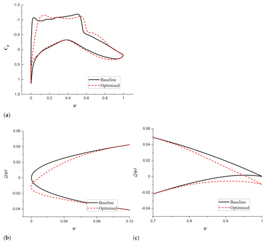
Figure 11.
Comparison of results for the RAE 2822 optimization using morphing leading and trailing edges. (a) distribution. (b) Leading edge shape. (c) Trailing edge shape.
However, the drag reduction achieved is lower than that achieved by using only the mLE. A possible interpretation could be that the optimization finds a local minimal starting from the baseline airfoil due to the pitfall of the gradient-based optimizer.
3.4.2. Starting from Optimized mLE
Another optimization case has been conducted, taking the optimized airfoil with mLE as initial. The drag coefficient converges to counts, a corresponding reduction of , which is larger than the optimization result that starts from the baseline. The shapes of baseline and optimized airfoil with morphing leading and trailing edge and the corresponding pressure coefficient distributions on the surface are compared in Figure 12. Similarly to the initial airfoil, the optimization results in a thicker leading edge by enlarging the upper leading edge radius. The leading edge slight drops around degrees. The chord decreases from 1 to m, and the chord-wise position of leading edge point moves around of chord length—primarily to satisfy the constant skin length constraints. The trailing edge moves upward, and the corresponding deflection angle is degrees. Additionally, the boat tail angle is enlarged, and hence, the camber near the trailing edge increases, resulting in a local lift increment at after of the chord. An analogical pressure coefficient distribution is obtained in the front comparing with the pressure coefficient distribution only using mLE in Figure 8b, and two smooth pressure recoveries replace the pressure drop around chord on the upper surface. Thus a lower shock wave drag is achieved.
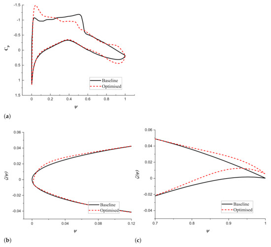
Figure 12.
Comparison of results for the RAE 2822 optimization using morphing leading and trailing edges, starting from the optimized morphing leading edge case. (a) distribution. (b) Leading edge shape. (c) Trailing edge shape.
The optimization results are summarized in Table 1. The moment coefficient is presented here for completeness, although it was not included in the optimization problem.

Table 1.
Forces and corresponding angles of attack for baseline and optimized morphing airfoils at a constant lift coefficient of .
3.5. Verification
The number of points on the airfoil is around 192, which is sufficient for lift and drag calculations. However, the optimum results for mLE show a complicated internal structure of the supersonic region. Thus, we generated finer computational meshes and simulated for baseline and the optimum airfoil with mLETE.
Table 2 illustrates the drag coefficient when , and the drag is represented in counts. is the friction drag component; is the drag induced by the pressure difference. This study confirms that the original mesh is sufficient for lift and drag. Figure 13 demonstrates the flow with original mesh and finer mesh; the supersonic regions are marked by Mach contour with solid black lines. A finer mesh is more conducive to showing the internal pattern of the supersonic region.

Table 2.
Result verification with finer meshes.
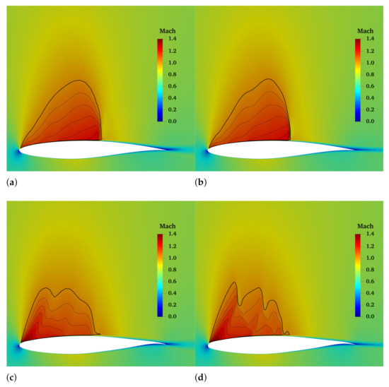
Figure 13.
Flow structure with original mesh (192 × 100) and finer mesh (400 × 200). (a) Baseline mesh 192 × 100. (b) Baseline mesh 400 × 200. (c) mLETE mesh 192 × 100. (d) mLETE mesh 400 × 200.
3.6. Mechanism of Drag Reduction
Table 3 presents the drag breakdown, in which is the change of the component with respect to that of baseline airfoil. By comparing the contribution of drag reduction of friction and pressure drag, we understand that the latter contributes the most drag reduction and the former has a slightly adverse effect. Note that, although the data in Table 3 are obtained based on original mesh, the finer meshes are used for illustrating the lambda shock pattern in Figure 14.

Table 3.
Drag breakdown (counts).
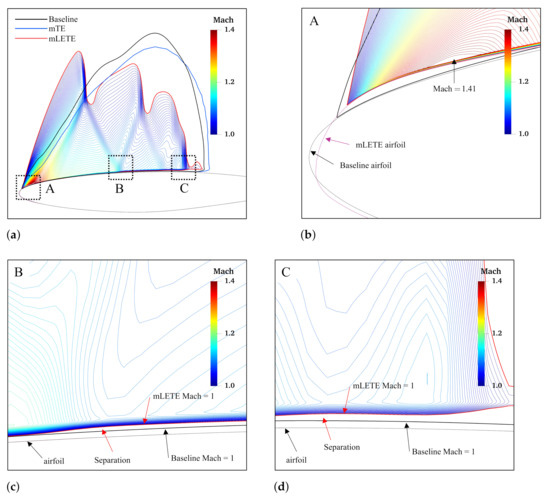
Figure 14.
Mach contour of baseline and optimized airfoils; please notice the lambda shock in the supersonic region and separation points. (a) Mach flow. (b) Leading edge. (c) Separation point 1. (d) Separation point 2.
Figure 14 demonstrates the region of the supersonic flow of baseline and optimized airfoils. There are two types of supersonic region shape: a single hump shape with a strong shock at around 55% chord that belongs to baseline and optimized mTE airfoil; a three-hump-like shape and lambda shock patterns for optimized mLE and mLETE. That phenomenon suggests the mechanisms behind the drag reduction of using mLE and mTE are different.
The optimized mTE is more like an improvement of supercritical airfoil, with a relatively flat top and a larger positive camber on the rear 25 percent of the airfoil. A flatter upper skin leads to a sluggish acceleration of the flow speed, extending the chord-wise length of the supersonic region. Furthermore, the extent of the supersonic flow is closer to the surface, the local supersonic Mach number is lower, and the terminating shock wave is weaker, thereby creating less drag. Reference [39] also reported that mTE was able to improve supercritical airfoil. Similar trends can be seen by comparing the distributions for the optimized airfoil with baseline airfoil in Figure 10.
One interesting finding is the appearance of the lambda shock patterns, which indicates the interaction between shock and boundary layers. As illustrated in Figure 14a, there are two lambda shocks and one normal shock at the end. The maximum Mach number is , which is observable on around 5% of the leading edge. The resulting first shock is much stronger than subsequent shocks, and produces a lower Mach number in the mainstream behind it. Figure 14b–d gives a close view of the supersonic region of optimized mLETE airfoil close to the boundary layer. In these figures, the solid, thin black line and the solid, thin purple line are the baseline and optimized mLETE airfoil; the possible separation zones are indicated by arrows. After passing zone A, the mainstream slows down until zone B, then accelerates again. The flow goes through the multi-stage acceleration and deceleration, and the terminating shock at end is weaker. A possible explanation for these results may be the larger disturbance of slope and curvature at the top of leading edge, as shown in Figure 15, in which the black dashed line represents baseline airfoil, whereas the red solid line represents optimized mLETE airfoil. Moreover, the similarity is observable by comparing the distribution, which is shown in Figure 8b, with that of an airfoil under an incompressible flow field.
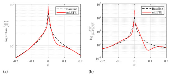
Figure 15.
Slope and curvature of baseline and optimized mLETE airfoils. (a) Slope; (b) curvature.
4. Conclusions
A gradient-based aerodynamic shape optimization framework was established in this work, through coupling with a feasible morphing airfoil geometry parameterization. The parameterization was developed to introduce local shape changes, preserve the attachment of shape at the wing-box region, and provide skin length control during optimization. The presented optimization framework was then applied to a single point optimization problem, aimed at reducing the drag coefficient of a transonic RAE 2822 in viscous flow at the cruise stage using mLE and mTE. The main contributions are summarized as follows:
- We provided the setup of a gradient-based aerodynamic optimization framework that is able to combine two main tools: the CST parameterization of the airfoil and the open-source code SU2 as a CFD engine. The framework projects the gradient already presented by SU2 to the CST domain, allowing the pure analytical calculation of the gradient of the relevant aerodynamic quantities with respect to few CST design variables. Thus, the optimization becomes efficient when the gradients are available.
- The optimization results show that a maximum drag reduction of was achieved using mLETE. In comparison, the optimization obtained a drag reduction using only mTE and for mLE.
- Compared with the mTE case, mLE is more suitable for eliminating the pressure drag.
- The mechanisms of drag reduction using mLE and the trailing edge are different. The optimized mTE creates a relatively flat top, slows down the flow acceleration, extends the supersonic region along the surface, and terminates a weaker shock. The optimized mLE shows a larger curvature at the top, resulting in a maximum Mach appearing at the leading edge. The successional multi-stage acceleration and deceleration lead to a weaker shock at the end.
The feasible morphing shape introduced in the paper does not include details about the morphing mechanism and the internal structures. The introduction of these components could further restrain the design space and limit the morphing capabilities, consequently limiting the improvement of aerodynamic performance.
This paper concerns only two-dimensional aerodynamic optimization of a morphing airfoil under steady flow. Different optimization results may be obtained if the unsteadiness and the consequent shock wave movement are considered. The authors encourage the development and implementation of the adjoint method for gradient evaluation when considering the flow unsteadiness.
Author Contributions
Conceptualization, Z.Z., A.D.G. and C.S.; methodology, Z.Z., A.D.G. and S.R.; project administration, S.R. and C.Y.; software, Z.Z. and A.D.G.; writing—original draft, Z.Z.; writing—review and editing, S.R. and C.S. All authors have read and agreed to the published version of the manuscript.
Funding
This research was partially funded by National Key Research and Development Program of China (grant number 2017YFB0503002) and the National Natural Science Foundation of China (grant number 11402013).
Institutional Review Board Statement
Not applicable.
Informed Consent Statement
Not applicable.
Data Availability Statement
The data presented in this study are available on request from the corresponding author.
Acknowledgments
Zhenkai Zhang acknowledges the financial support from the China Scholarship Council (grant number 201806020280).
Conflicts of Interest
The authors declare no conflict of interest.
References
- Miller, E.J.; Cruz, J.; Lung, S.F.; Kota, S.; Ervin, G.; Lu, K.J.; Flick, P. Evaluation of the Hinge Moment and Normal Force Aerodynamic Loads from a Seamless Adaptive Compliant Trailing Edge Flap in Flight. In Proceedings of the 54th AIAA Aerospace Sciences Meeting, San Diego, CA, USA, 4–8 January 2016; Number January in AIAA SciTech Forum. American Institute of Aeronautics and Astronautics: Reston, VA, USA. [Google Scholar] [CrossRef]
- Ting, E.; Chaparro, D.; Nguyen, N.; Fujiwara, G.E.C. Optimization of Variable-Camber Continuous Trailing-Edge Flap Configuration for Drag Reduction. J. Aircr. 2018, 55, 2217–2239. [Google Scholar] [CrossRef]
- De Gaspari, A.; Moens, F. Aerodynamic Shape Design and Validation of an Advanced High-Lift Device for a Regional Aircraft with Morphing Droop Nose. Int. J. Aerosp. Eng. 2019, 2019, 1–21. [Google Scholar] [CrossRef]
- Yang, Y.; Wang, Z.; Lyu, S. Comparative study of two lay-up sequence dispositions for flexible skin design of morphing leading edge. Chin. J. Aeronaut. 2020, 4–11. [Google Scholar] [CrossRef]
- Design of compliant mechanism-based variable camber morphing wing with nonlinear large deformation. Int. J. Adv. Robot. Syst. 2019, 16, 172988141988674. [CrossRef]
- Fincham, J.; Friswell, M. Aerodynamic optimisation of a camber morphing aerofoil. Aerosp. Sci. Technol. 2015, 43, 245–255. [Google Scholar] [CrossRef]
- Lyu, Z.; Martins, J.R.R.A. Aerodynamic Shape Optimization of an Adaptive Morphing Trailing-Edge Wing. J. Aircr. 2015, 52, 1951–1970. [Google Scholar] [CrossRef]
- De Gaspari, A.; Ricci, S. A Two-Level Approach for the Optimal Design of Morphing Wings Based On Compliant Structures. J. Intell. Mater. Syst. Struct. 2011, 22, 1091–1111. [Google Scholar] [CrossRef]
- Dumont, A. Adjoint-Based Aerodynamic Shape Optimization Applied to Morphing Technology on a Regional Aircraft Wing. In Morphing Wing Technologies; Elsevier: Amsterdam, The Netherlands, 2018; pp. 145–174. [Google Scholar] [CrossRef]
- Suzuki, H.; Rinoie, K.; Tezuka, A. Laminar airfoil modification attaining optimum drag reduction by use of airfoil morphing. J. Aircr. 2010, 47, 1126–1132. [Google Scholar] [CrossRef]
- Kan, Z.; Li, D.; Shen, T.; Xiang, J.; Zhang, L. Aerodynamic characteristics of morphing wing with flexible leading-edge. Chin. J. Aeronaut. 2020, 33, 2610–2619. [Google Scholar] [CrossRef]
- Kulfan, B.M. Universal Parametric Geometry Representation Method. J. Aircr. 2008, 45, 142–158. [Google Scholar] [CrossRef]
- Sripawadkul, V.; Padulo, M.; Guenov, M. A comparison of airfoil shape parameterization techniques for early design optimization. In Proceedings of the 13th AIAA/ISSMO Multidisciplinary Analysis and Optimization Conference, Ft. Worth, TX, USA, 13–15 September 2010; pp. 1–9. [Google Scholar] [CrossRef]
- Calleja, A.; Bo, P.; González, H.; Bartoň, M.; López de Lacalle, L.N. Highly accurate 5-axis flank CNC machining with conical tools. Int. J. Adv. Manuf. Technol. 2018, 97, 1605–1615. [Google Scholar] [CrossRef]
- González, H.; Calleja, A.; Pereira, O.; Ortega, N.; López De Lacalle, L.N.; Barton, M. Super abrasive machining of integral rotary components using grinding flank tools. Metals 2018, 8, 24. [Google Scholar] [CrossRef]
- Magrini, A.; Benini, E. Aerodynamic Optimization of a Morphing Leading Edge Airfoil with a Constant Arc Length Parameterization. J. Aerosp. Eng. 2018, 31, 1–9. [Google Scholar] [CrossRef]
- Leal, P.B.C.; Hartl, D.J. Structurally Consistent Class/Shape Transformation Equations for Morphing Airfoils. J. Aircr. 2019, 56, 505–516. [Google Scholar] [CrossRef]
- De Gaspari, A.; Ricci, S. Knowledge-Based Shape Optimization of Morphing Wing for More Efficient Aircraft. Int. J. Aerosp. Eng. 2015, 2015, 1–19. [Google Scholar] [CrossRef]
- Marco, A.; Martinez, J.J. Polynomial least squares fitting in the Bernstein basis. Linear Algebra Its Appl. 2010, 433, 1254–1264. [Google Scholar] [CrossRef]
- Ricci, S.; De Gaspari, A.; Gilardelli, A.; Airoldi, A. Design of a Leading Edge Morphing Based on Compliant Structures for a Twin-Prop Regional Aircraft. In Proceedings of the 2018 AIAA/AHS Adaptive Structures Conference, Kissimmee, FL, USA, 8–12 January 2018; American Institute of Aeronautics and Astronautics: Reston, VA, USA; pp. 1–19. [Google Scholar] [CrossRef]
- Arena, M.; Concilio, A.; Pecora, R. Aero-servo-elastic design of a morphing wing trailing edge system for enhanced cruise performance. Aerosp. Sci. Technol. 2019, 86, 215–235. [Google Scholar] [CrossRef]
- Kota, S.; Flick, P.; Collier, F.S. Flight Testing of FlexFloil TM Adaptive Compliant Trailing Edge. In Proceedings of the 54th AIAA Aerospace Sciences Meeting, Reston, VA, USA, 4–8 January 2016; AIAA SciTech Forum;. American Institute of Aeronautics and Astronautics: Reston, VA, USA. [Google Scholar] [CrossRef]
- Popov, A.V.; Grigorie, L.T.; Botez, R.M.; Mamou, M.; Mébarki, Y. Real Time Morphing Wing Optimization Validation Using Wind-Tunnel Tests. J. Aircr. 2010, 47, 1346–1355. [Google Scholar] [CrossRef]
- De Gaspari, A.; Riccobene, L.; Ricci, S. Design, Manufacturing and Wind Tunnel Validation of a Morphing Compliant Wing. J. Aircr. 2018, 55, 2313–2326. [Google Scholar] [CrossRef]
- Houghton, E.L.; Carpenter, P.W.; Collicott, S.; Valentine, D. Aerodynamics for Engineering Students; Butterworth-Heinemann: Oxford, UK, 2016; p. 688. [Google Scholar]
- De Gaspari, A.; Ricci, S.; Antunes, A.; Odaguil, F.; Lima, G. Expected performances. In Morphing Wing Technologies: Large Commercial Aircraft and Civil Helicopters; Elsevier Science: Amsterdam, The Netherlands, 2018; pp. 175–203. [Google Scholar] [CrossRef]
- You, H.; Kim, S.; Joe, W.Y.; Yun, G.J. New Concept for Aircraft Morphing Wing Skin: Design, Modeling, and Analysis. AIAA J. 2019, 57, 1786–1792. [Google Scholar] [CrossRef]
- Biancolini, M.E. Fast Radial Basis Functions for Engineering Applications; Springer International Publishing: Berlin/Heidelberg, Germany, 2018; pp. 1–357. [Google Scholar] [CrossRef]
- Rendall, T.C.; Allen, C.B. Efficient mesh motion using radial basis functions with data reduction algorithms. J. Comput. Phys. 2009, 228, 6231–6249. [Google Scholar] [CrossRef]
- Dwight, R.P. Robust Mesh Deformation using the Linear Elasticity Equations. In Computational Fluid Dynamics 2006; Springer: Berlin/Heidelberg, Germany, 2009; pp. 401–406. [Google Scholar] [CrossRef]
- Economon, T.D.; Palacios, F.; Copeland, S.R.; Lukaczyk, T.W.; Alonso, J.J. SU2: An open-source suite for multiphysics simulation and design. AIAA J. 2016, 54, 828–846. [Google Scholar] [CrossRef]
- Spalart, P.; Allmaras, S. A one-equation turbulence model for aerodynamic flows. In Proceedings of the 30th Aerospace Sciences Meeting and Exhibit, Washington, DC, USA, 6–9 January 1992; Number 1. American Institute of Aeronautics and Astronautics: Reston, VA, USA; pp. 5–21. [Google Scholar] [CrossRef]
- Bueno-Orovio, A.; Castro, C.; Palacios, F.; Zuazua, E. Continuous adjoint approach for the spalart-allmaras model in aerodynamic optimization. AIAA J. 2012, 50, 631–646. [Google Scholar] [CrossRef]
- Economon, T.D.; Alonso, J.J.; Albring, T.A.; Gauger, N.R. Adjoint Formulation Investigations of Benchmark Aerodynamic Design Cases in SU2. In Proceedings of the 35th AIAA Applied Aerodynamics Conference, Denver, CO, USA, 5–9 June 2017; American Institute of Aeronautics and Astronautics: Reston, VA, USA. [Google Scholar] [CrossRef]
- Kenway, G.K.; Mader, C.A.; He, P.; Martins, J.R. Effective adjoint approaches for computational fluid dynamics. Prog. Aerosp. Sci. 2019, 110, 100542. [Google Scholar] [CrossRef]
- Economon, T.D. Optimal Shape Design Using an Unsteady Continuous Adjoint Approach. Ph.D. Thesis, Stanford University, Stanford, CA, USA, 2014. [Google Scholar]
- Lozano, C. Discrete surprises in the computation of sensitivities from boundary integrals in the continuous adjoint approach to inviscid aerodynamic shape optimization. Comput. Fluids 2012, 56, 118–127. [Google Scholar] [CrossRef]
- Lozano, C. Adjoint viscous sensitivity derivatives with a reduced gradient formulation. AIAA J. 2012, 50, 203–214. [Google Scholar] [CrossRef]
- Guo, T.; Bai, J.; Yyang, T. Influence of continuous trailing-edge variable camber on aerodynamic characteristics of transonic airfoils. Acta Aeronaut. Astronaut. Sin. 2016, 2, 513–521. [Google Scholar]
Publisher’s Note: MDPI stays neutral with regard to jurisdictional claims in published maps and institutional affiliations. |
© 2021 by the authors. Licensee MDPI, Basel, Switzerland. This article is an open access article distributed under the terms and conditions of the Creative Commons Attribution (CC BY) license (http://creativecommons.org/licenses/by/4.0/).