Article

Net-Shape NiTi Shape Memory Alloy by Spark Plasma Sintering Method

1
FZU—Institute of Physics of Czech Academy of Sciences, Na Slovance 1999/2, 182 21 Prague, Czech Republic
2
Department of Metals and Corrosion Engineering, University of Chemistry and Technology, Prague, Technická 5, 166 28 Prague, Czech Republic
3
Institute for Nanomaterials, Advanced Technologies and Innovation, Technical University of Liberec, Studentska 2, 461 17 Liberec, Czech Republic
4
Department of Physical and Chemical Methodologies for Engineering, University of Catania, Viale A. Doria 6, 95125 Catania, Italy
5
Department of Civil Engineering and Architecture and UdR-Catania Consorzio INSTM, University of Catania, Viale Andrea Doria 6, 95125 Catania, Italy
*
Author to whom correspondence should be addressed.
Appl. Sci. 2021, 11(4), 1802; https://doi.org/10.3390/app11041802
Submission received: 22 December 2020 / Revised: 4 February 2021 / Accepted: 13 February 2021 / Published: 18 February 2021
(This article belongs to the Section Chemical and Molecular Sciences)

Abstract

:
An analysis of the shape memory effect of a NiTi alloy by using the spark plasma sintering approach has been carried out. Spark plasma sintering of Ti50Ni50 powder (20–63 µm) at a temperature of 900 °C produced specimens showing good shape memory effects. However, the sample showed 2.5% porosity due to a load of 48 MPa. Furthermore, an apparent shape memory effect was recorded and the specimens were characterized by uniformity in chemical composition and shape memory alloys of NiTi showed significant austenite phases with a bending strain recovery of >2.5%.

1. Introduction

Demands for NiTi alloys for applications in various fields in engineering and medicine make this material one of the most investigated in both academia and industry. NiTi alloys with chemical compositions that are close to equiatomic possess the properties of good corrosive resistance, biocompatible natures, superior mechanical performances, and the functional properties of shape memory and superelasticity (SE) [1,2,3]. These properties open up the application areas of NiTi alloys with shape memory effects for various application-orientated industries in material engineering, such as the aerospace industry, actuators, dampers, vibrators, and resonators. The shape memory effects (SMEs) of NiTi alloys relate to the transformation of solid-state phases from the austenite cubic B2 structure to martensitic monoclinic B19′ structure [4,5]. Ni–Ti offers two candidate successors with lower entropies—a monoclinic B19′ martensite and a rhombohedrally distorted martensite (R phase). The R phase can be imagined as a rhombohedral distortion of the cubic austenitic phase, with one of the four [1 1 1] directions of the cubic austenite being stretched. The transformation of the phase occurs in NiTi and shape memory alloys during cooling and heating cycles [6,7,8,9]. The loading causes the martensitic transformation and then induces a superelastic effect in the martensitic phase and returns to the austenite phase during unloading. The functional behaviors of the SME and SE effect of NiTi alloys allow the material to restore 10% of strain [10].
Based on wide-field applications, there are various methods available for the manufacturing of NiTi alloys. One of the general and commercially approved methods of fabrication is the casting method. However, this conventional method is a multistep process that undergoes melting, casting, and postprocessing steps until the final product is achieved [11,12]. Melting may lead to micro- and macrosegregations that could result in chemical inhomogeneity of elemental composition and oxidization during processing. This may lead to an increase in the level of impurities in the final product. The postprocessing step of the machining could harden the NiTi alloy which may be resistant to deformation. These obstacles and limitations during standard manufacture of NiTi alloys have caused researchers to find other simpler, time-saving, effective steps for the manufacture of NiTi alloys [13,14,15].
Recently, researchers have focused on alternative routes to achieve the manufacture of NiTi alloys. Powder metallurgy (PM) is the integrated process of compaction and sintering. PM has been emerging to meet the challenge of conventional casting methods by using powder routes [2]. The PM route offers minimum contamination of impurities such as oxygen and carbon contents, without any segregation of phases, thus avoiding chemical inhomogeneity and a one-step process to reach the stage of the final product [16,17,18]. PM parts of NiTi alloys show better physical and machining properties due to their finer and homogenous microstructures. However, one of the limitations lies in the area of manufacture of complex shapes by the PM route. There are various routes of PM methods such as Conventional sintering (CS), Self-propagating high-temperature synthesis (SHS), Metal injection molding (MIM), Hot isostatic pressing (HIP), Spark plasma sintering (SPS), and Plasma melting (PM), microwave sintering (MWS) methods [19,20,21,22]. Out of these sintering processes, the spark plasma sintering method stands out due to the short processing time of the reaction process. The SPS process can be feasible at low sintering temperatures, ranging from 900 to 1100 °C, which allows uniform sintering and avoids any undesired reaction products and high heating rates, with a high consolidation process for the by-products. However, the only limitation is that the process is unable to produce materials with complex shapes. SPS is a method in which integration of DC electrical pulse currents along with uniaxial pressure to consolidate powders occurs. Simultaneously with the application of pressure, load acts as an additional driving force for the sintering process, resulting in higher densification and grain growth in sintered alloys. Earlier researchers have investigated processing parameters, such as sintering time and temperature, and the magnitude of load plays a significant role in the final microstructure and densification of the NiTi alloys [23]. The sintering temperature plays a significant role in the densification mechanisms, microstructural evolution, and mechanical properties of spark plasma sintered alloy. The particle rearrangement, localized deformation, and bulk deformation appear to be sequences of the sintering mechanism depending on the size range of powder particles used for consolidation. The compact sintered alloy strength depends on the microstructure that is derived from the arrangement of micrograins [24,25].
In the SPS process, graphite die has been used as the standard material for sintering; however, austenitic steel has recently emerged as a new material that could replace graphite [26]. Consequently, it could save heat loss from the materials and achieve higher densities in the sintered by-product. As a result, the sintering process was functional with lower sintering times and temperatures, which could lead to uniformity in structure. The SPS process in the field of NiTi alloys mostly covers the output in the areas of densification with the microstructural evolution of sintered NiTi alloys. However, NiTi alloys are more applicable in terms of functional properties of the shape memory effect. SME properties are hardly discussed for the spark plasma sintered NiTi alloys. Some researchers have gone to the extent of assessing mechanical properties under compression stress and induced plastic strain. However, there is still a lack of research in the analysis of the SME effect of the sintered alloy in terms of grain distribution.
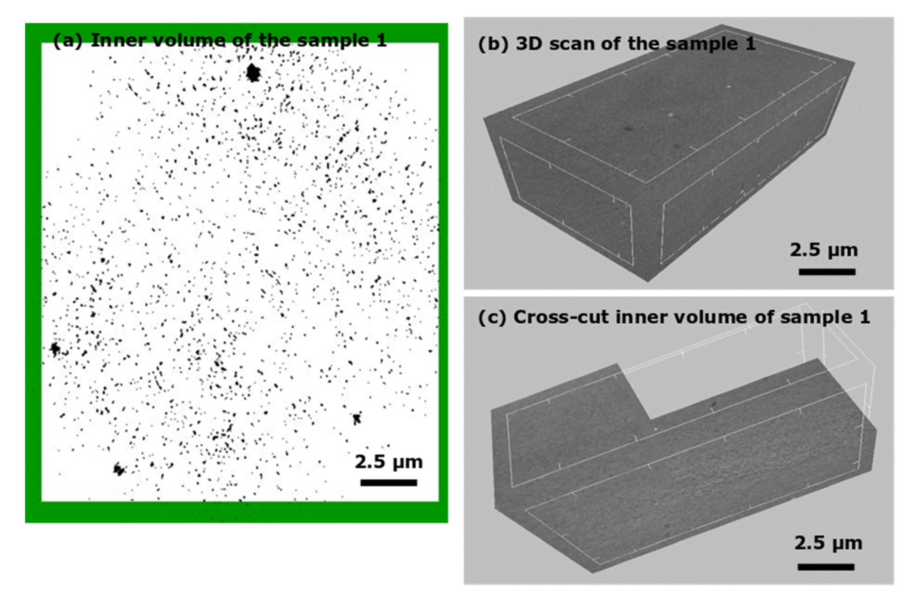
The work aims to fabricate shape memory alloys of NiTi by the SPS process. Although some articles mention this alloy, there is hardly any work published on the investigation of shape memory behavior and functional properties of alloys. Rather, most of the work on SPS concludes on microstructures, compacts, phases by EDX, and, finally, hardness. In this article, the mechanical behavior of the NiTi alloy in terms of SME is investigated. Functional properties such as shape memory behavior in relation to strain, with the stress-controlled mode and behavior of shape memory alloys (SMAs) being investigated, aiming at preparing a near-net-shape memory alloys of NiTi by the SPS process. The shape memory effect of the sintered NiTi alloys was investigated based on phase transformation as a function of temperature. The grain distribution of the sintered alloy was examined by the electron backscatter method. The polycrystalline grain growth was confirmed from the cross-section of the sintered NiTi alloy along with the thickness of the consolidation. The internal volumes of the NiTi alloys were examined by the microcomputed tomography method. Thermo-mechanical properties of the NiTi alloys were investigated to establish the functional properties of SME behavior.

2. Materials and Methods

2.1. Raw Materials for the Fabrication of NiTi Alloys

Ni50Ti
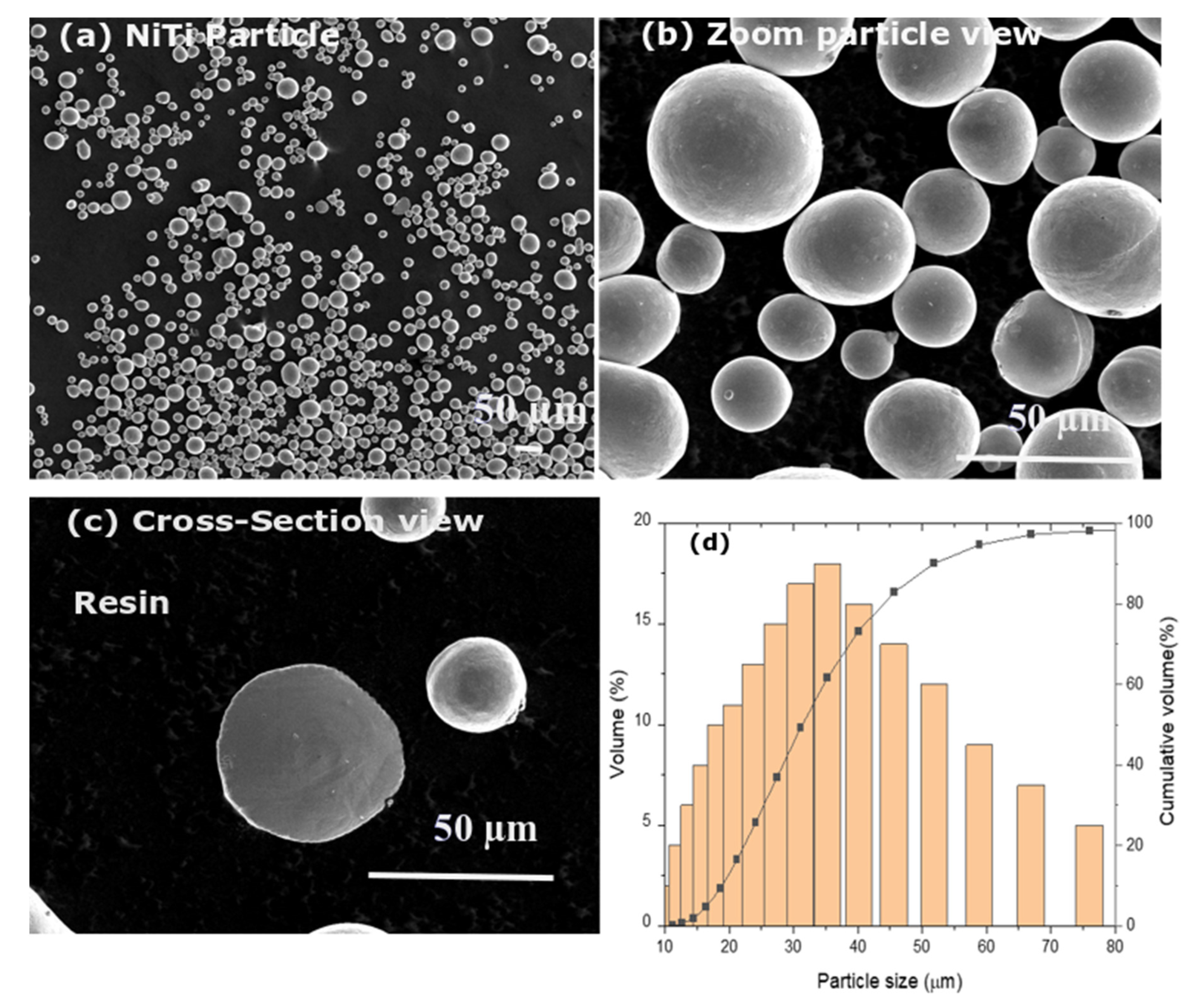
50 powders with spherical particle sizes of 20–63 µm (purity: 99.5%) and without any porosity were used for the preparation of NiTi alloys by SPS process. The gas-atomized NiTi powders were purchased from American Elements (AE), USA. The elemental composition of the Ni:Ti powders was 50:50 (at.%). Figure 1a–d display the surface morphologies of the NiTi powder particles, the zoom view of the powders, cross-section view, and particle size distributions. The average particle size of NiTi powder (davg) was 50 µm. The sizes of the largest particles fall within range of 30–40 µm.

2.2. Preparation of NiTi Alloy from the Consolidation of NiTi Powders Using the SPS Process

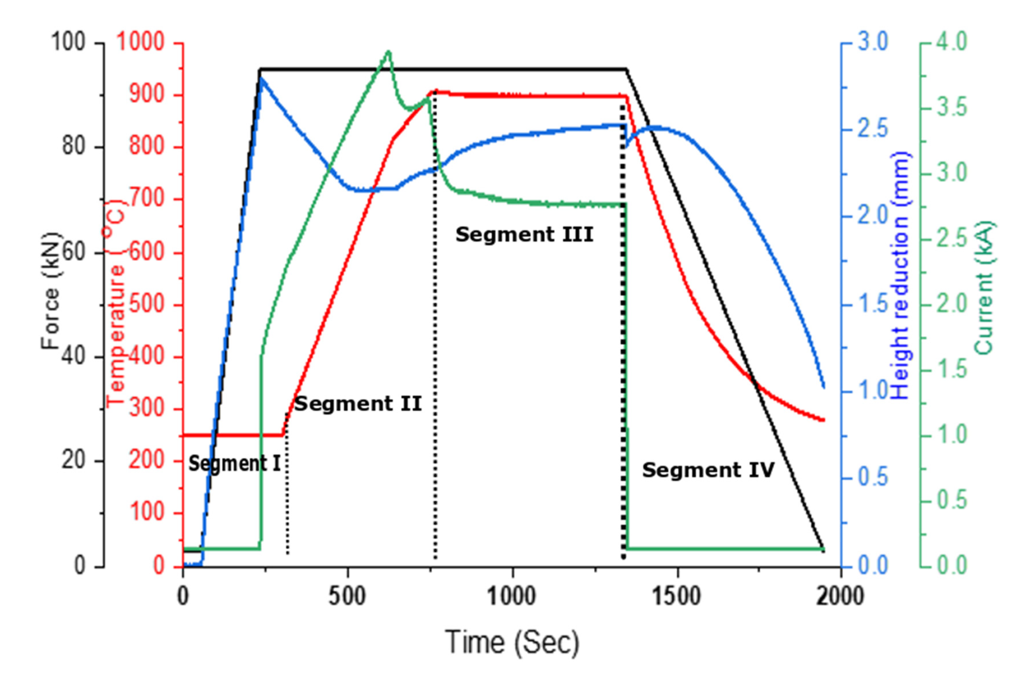
The influence of sintering temperature, applied pressure, and holding time on the relative reduction in sample thickness derived from the relative displacement of punches during the SPS process is displayed in Figure 2. The whole process of the SPS compaction was divided into four segments. Segment I is characterized by the application of a 95 kN (approx. 48 MPa) load with a total duration of 180 s. In the case of the 50 mm sample, the compaction temperature was 900 °C and was achieved by two steps: powder was heated from 300 up to 800 °C with a heating rate of 100 °C/min. In the second step, the heating rate was lowered down to 50 °C/min and the sample was heated until reaching 900 °C, which was maintained for 10 min. Then, rapid cooling was carried out and the applied load was constantly lowered for 10 min until reaching 3 kN. Thereafter, a temperature of 900 °C was reached at 750 s in segment II. The fixed temperature with a fixed load was stable and kept constant for fixed holding time for 600 s (segment III) and then followed by machine cooling to room temperature (RT) (segment IV). The powders were placed into a graphite die with a 50 mm diameter and then consolidated using SPS equipment. Sample 1 was prepared at a sintering temperature of 900 °C and a load of 48 MPa for 10 min. NiTi powders were compressed with uniaxial pressure within the graphite die. After sintering, discs with 50 mm diameters and 2 mm in height were produced. Figure 2 displays the process parameters for the experimental set-up of the sintered sample.
For segment I, the punch displacement corresponding to height reduction had no significant effect until 2.5 mm, as the pressure was applied at a lower temperature. In this zone, consolidation of the NiTi powders was observed due to the cold compaction. The height reduction changed after the small plateau when reaching the temperature of approximately 570 °C as a result of activation of nondiscrete dislocation movements as well as the implementation of partially considered diffusion bonding between powder particles (especially on the sites of mutual contact, segment II).
This step induces the Joule heating effect within the powders to generate localized necking within the neighboring powder particles. During segment III, holding pressure and temperature steps promoted growth and plastic deformation within the necking zones of the powder particles. Thus, the diffusion of powder particles progressed in a short processing time resulting in a dense by-product of NiTi samples. The effect of Joule heating was increased with an increase of 900 °C for sintering temperature. The powder surface smoothens at sintering temperature due to the thermal softening effect and grain shape changes with the applied load. These combined effects of particle smoothing and grain reshaping influenced the internal voids within the compact of the sintered sample. The effect of particle sizes significantly contributes to the contact surface in the vicinity region. If the particle sizes are lower, the contact surface within the vicinity region increases and allows diffusion of the lattice surface which leads to a reduction in pore size. Moreover, the size of the particle was also influenced by pressure acting on it.

2.3. Characterization Techniques for Sintered Samples

The microstructures of both powder and sintered NiTi alloys were characterized by using scanning electron microscopes: a SEM, FEI Quanta 3D Dual-Beam SEM/FIB scanning electron microscope equipped with field emission cathode; one from Thermo Fisher Scientific, Brno, Czech Republic); one from Tescan FERA 3, Brno, Czech Republic. The grain size was observed on the surface of the sintered sample by an optical microscope (OM, Thorlabs, CEA 1350). The sample specification for optical, SEM, and EBSD was 5 × 5 mm. The optical microstructure was revealed after grinding, polishing and etching with Kroll’s reagent (5 mL HNO3, 10 mL HF, and 85 mL H2O). The EBSD sample followed the procedure as samples were hot mounted in conductive Bakelite and metallographically prepared by modified procedure for nickel (ASTM C-56 recipe). The colloidal silica was used in the last polishing step and surface was finished by etching in Kroll’s reagent. Grain orientation and phase map of the sintered NiTi alloys was performed by the electron backscatter method (EBSD, using the EDAX DigiView V camera).
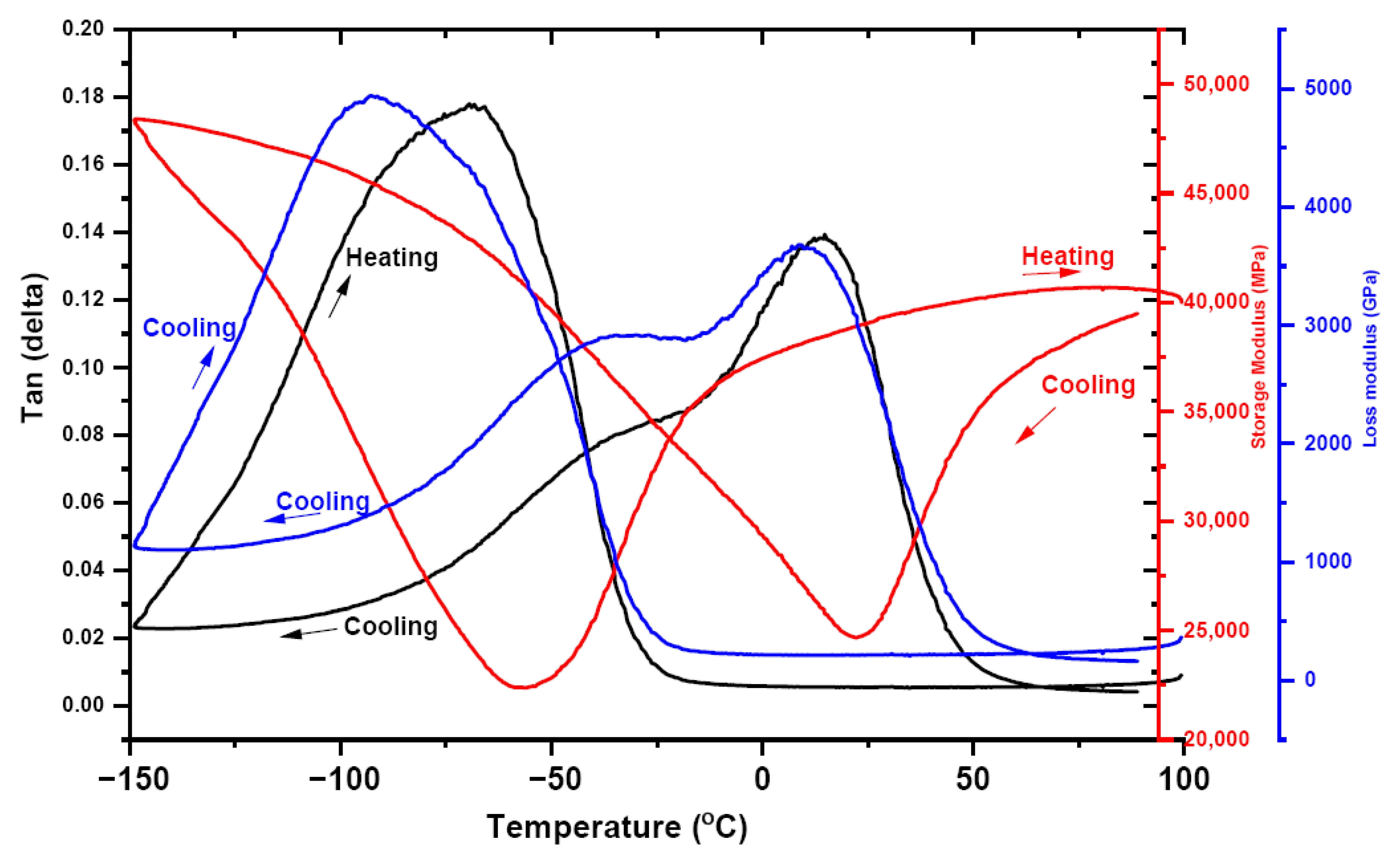
The dimension of the sample for the Differential Scanning Calorimetry (DSC) test was 1 × 1 × 0.3 mm, whilst for the DMA test the sample size was 22 × 3 × 0.3 mm. For bending for Thermo-mechanical Analysis (TMA), the sample dimension was 15 × 3 × 0.3 mm and for the tensile test sample, the dimension was gauge length 20 × 3 × 0.3 mm. A thermomechanical analyzer was used on the SPS NiTi sample (TMA, LINSEIS L75 Cryo Linseis, Selb, Germany) to observe the deflection in terms of displacement during the cooling and heating profiles. An 8000 Perkin Elmer DMA machine was used to carry out the test with a frequency of 0.1 Hz and a heating and cooling rate of 2 K/min in the temperature range of −150 to +100 °C to observe the shape memory effect [9].

3. Results and Discussion

3.1. Surface Morphology of the Sintered NiTi Alloy Sample

The quality of the sintered NiTi samples was examined from the surface and cross-section of the sample. The surface features revealed the upper zone of the morphology with particles interconnected with others and with necking from one particle to another particle during spark plasma sintering. During the SPS process, densification of the NiTi powder happens due to melting and vaporization of the powder surface during sintering temperature and plasma current flow within the powder particles. Typical optical and SEM analyses were carried out to investigate the microstructure of the NiTi alloy after the sintering process under different conditions of sintering temperature and applied load.
The optical micrograph of the sintered NiTi sample (sample 1) is shown in Figure 3a. The various grain sizes are uniformly distributed in the isotropic direction and have some porosity with neighboring particles. The sample microstructure was examined more in-depth, with the cross-sections of the samples being shown in Figure 3b,c. Sample 1 displays a cross-section view of the NiTi alloy along with the height of thickness. Sample 1 shows the various grain morphologies with internal pores and voids within the grain arrangement (Figure 3c). By observing the samples at higher magnification, voids are more prominent with the adjoining particles in sample 1 (Figure 3c).

3.2. Thermal Characterization of NiTi Samples for Transformation Temperatures

NiTi sample transforms with a solid-state transformation of phases as a function of heating and cooling cycles. To understand the phase change in the sintered NiTi alloy, the transformation temperature regarding phase changes was investigated for NiTi powder (sample 1 (Figure 4)).
Upon cooling (below line), NiTi powder showed the transformation of austenite to the R phase with an initial temperature of Rs: 40 °C and end temperature of the R Phase of Rf: −2 °C, and martensite starting temperature of Ms: −19 °C, with an end temperature of Mf: −47.6 °C. On heating (above line), the transformation from martensite to the R phase with an R phase starting temperature of Rs: −8.9 °C and end R phase temperature of Rf: 29.7 °C, with an austenite starting temperature of As: 32 °C and austenite end temperature of Af: 62 °C. There are some other unidentified peaks that may develop due to different grain size transformations. However, the sintered sample (SPS_1) shows the response of transformation peaks towards lower temperature. The sample exhibited transformation from austenite to the R phase or martensite at a starting temperature of Ms: −19 °C and end temperature of Mf: −47.6 °C during cooling (coincides with powder) and from martensite to austenite with an end temperature of 29.7 °C during heating (combination of R and austenite phases). In the sintered sample, wider peaks were observed that may correspond to homogenization of the NiTi alloy.

3.3. Phase Characterization and Grain Orientation of the Sintered NiTi Alloy

Figure 5a,b displays the cross-section image and corresponding electron backscattered diffraction analysis of the image for grain orientation and phase analysis. The sample contain joined particles of original powder with pores between them (Figure 5a). Some pores were filled with polishing solutions and suspension, which are hard to remove even in vacuum. Their droplets can be seen as heaps in Figure 5a. The orientation map in Figure 5b shows the expected isotropic distribution of orientations and prove some particles contain more than one grain. The structure of Face centered Cubic (FCC) austenite was the only structure observed with the EBSD method—i.e., all observed Kikuchi patterns can be attributed to the austenite structure (Figure 5c).

3.4. Inner Volume of the NiTi Alloy by Microcomputed Tomography

The sintered NiTi alloy prepared by the SPS process displays porosity of the cross-sectional features of the alloy. The inner volume of the alloy was investigated by microcomputed tomography technique.
Figure 6a–c displays the porosity of sample 1 with a 3D and cross-cut view of the sample. The black dots represent the voids and porosity of the sample within the white region of the volume of the sample. The overall porosity with the samples including open and closed forms shows within 2.5%.

3.5. Mechanical Response of the NiTi Sample

3.5.1. Thermo-Mechanical Analysis of the NiTi Sample

Thermo-mechanical analysis of the NiTi alloy was carried out in bending mode. The samples were positioned in transverse positions along with the applied load. Fixed loads of 200 and 500 mN were applied on both the samples in bending mode. The samples were cooled, which was followed by heating, with the response of displacement as delta (µm) and coefficient of thermal expansion (CTE, E-6/K). The samples were observed with a hysteresis effect and the transformation temperature corresponds to martensite and austenite phases. Sample 1 shows a wider area for the hysteresis effect. There is a slight shift upwards in transformation temperature towards a higher temperature as confirmed by the DSC analysis. Figure 7 display the response of displacement and CTE of sample 1 at two different loads of 200 and 500 mN.

3.5.2. Shape Memory Effect of NiTi Samples

Figure 8 shows the bending response of the NiTi samples and recovery to initial position after heating. The samples were tested at various testing temperatures of cooling at −50 and −25 °C, until heating testing temperatures of 100 °C, with steps of 25 °C. The response of stress versus strain behavior of the sample shows loading and unloading with strain up 3%, heating add up steps for fully recover of strain in the sample. The transition of non-hysteresis behavior at cooling testing temperature towards elastic response of the sample at heating temperature of 100 °C was observed.
The transition is more effective for sample 1 from −25 to 25 °C. The response of the sample from −25 to +25 °C is more prominent with significant changes—from nonelastic behavior towards elastic response. Heating steps confirm the shape memory behaviors of the NiTi samples. The response of the sample at testing temperatures of −75 and −50 °C overlapped in response; however, the nonelastic behavior of the sample remained until −25 °C. The nonelastic response also confirms the shape memory behavior during heating after unloading.
Figure 9 shows the storage modulus, loss modulus, and tan δ as a function of temperature for sample 1. The sample responded at constant stress of 300 MPa, as a function of cooling to heating temperature ranges. The storage and loss moduli of the NiTi alloy shows the values within range of 50 × 103 MPa and 5 × 10³ GPa for sample 1. Tan δ shows a response of 0.14 during cooling, with an increase in damping frequency of 0.18 at heating stage on transformation of martensite to austenite phases. The storage and loss moduli values are 65 × 103 MPa and 5 × 10³ GPa, with a damping value 0.12 during the heating cycle. The transformation of the austenite to martensite and martensite to austenite peaks are very prominent and correspond to loss modulus response. The mechanical response of sample 1 in tensile mode is shown in Figure 10. Two experiments were performed in sample 1, and tension shows strain of 0.6%.

4. Discussion on the NiTi Alloy in Terms of Polycrystallinity and Composition

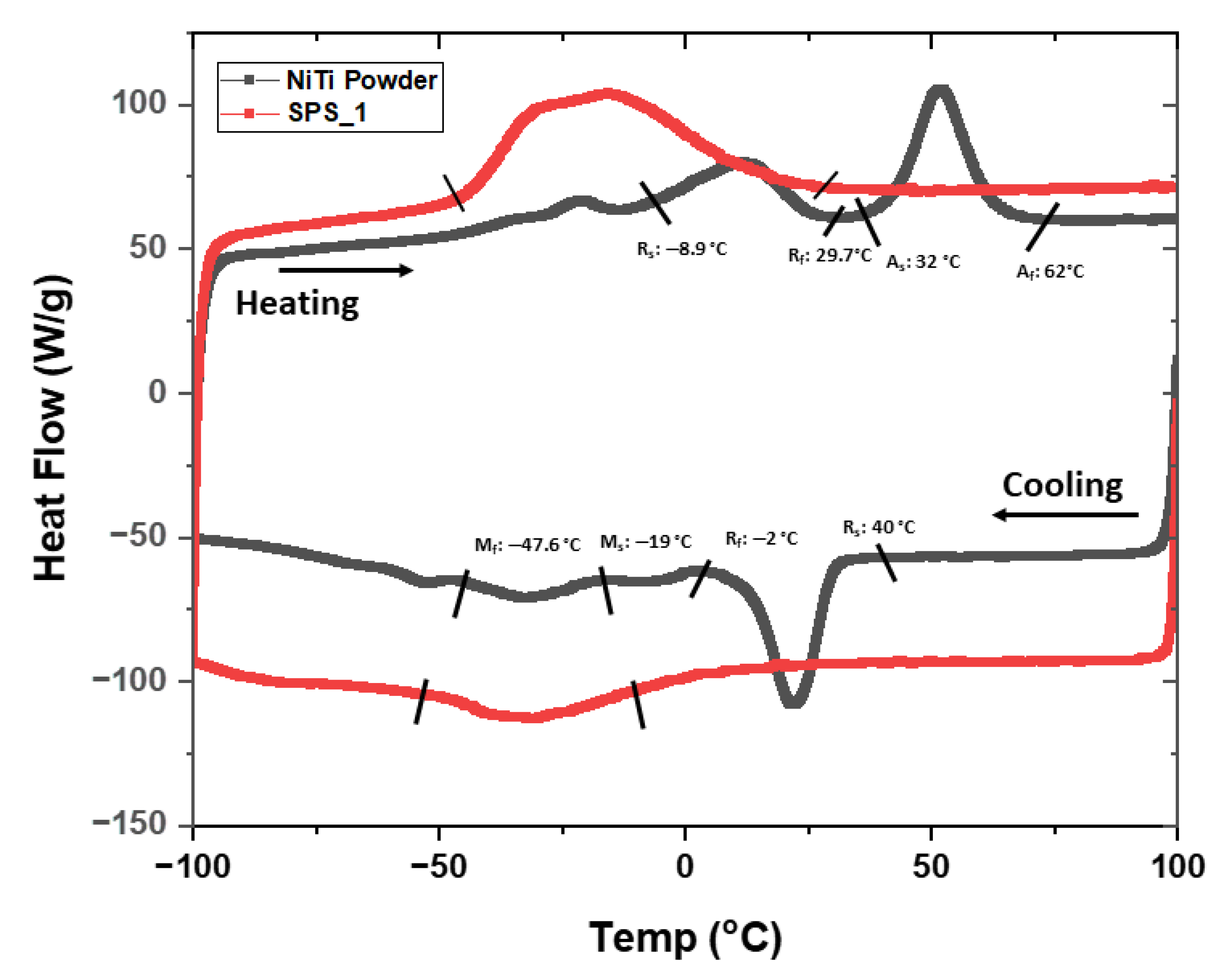
Since our aim was to study the structure of NiTi alloys, the martensitic transformation and shape memory behavior of the spark plasma sintered NiTi alloy, the relation between structure of the sintered NiTi compact alloy, and martensitic transformation were studied using thermal and thermo-mechanical characterizations. DSC curves of the SPS sintered NiTi alloy (Figure 4) show no distinct peaks that may be a result of homogenization. NiTi powder shows two endothermic peaks during heating and two exothermic peaks in the cooling mode. The heating peak indicates a B19′→R and R→B2 transformations and two-step transformation with cooling as B2→R and R→B19′ for the first and second steps, respectively [22,23]. The wider distribution of peaks in the SPS sample may relate to the elimination of the dislocation networks during homogenization. The decrease in the transformation temperatures in the SPS sample may result from a local increase in Ni content in the B2 matrix and may be due to some local stress field within grains generated due to the compaction of the applied load in the sintering process [24].
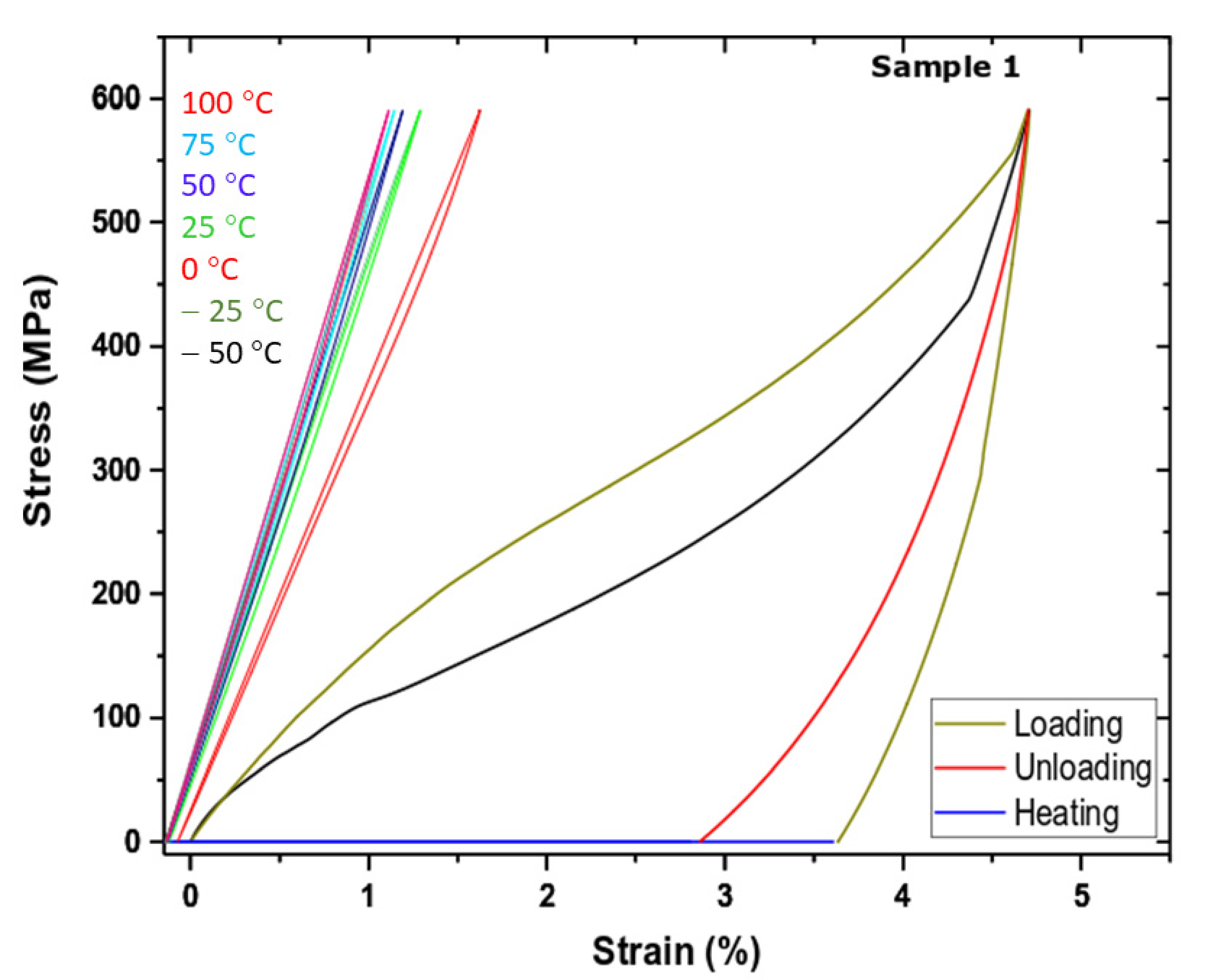
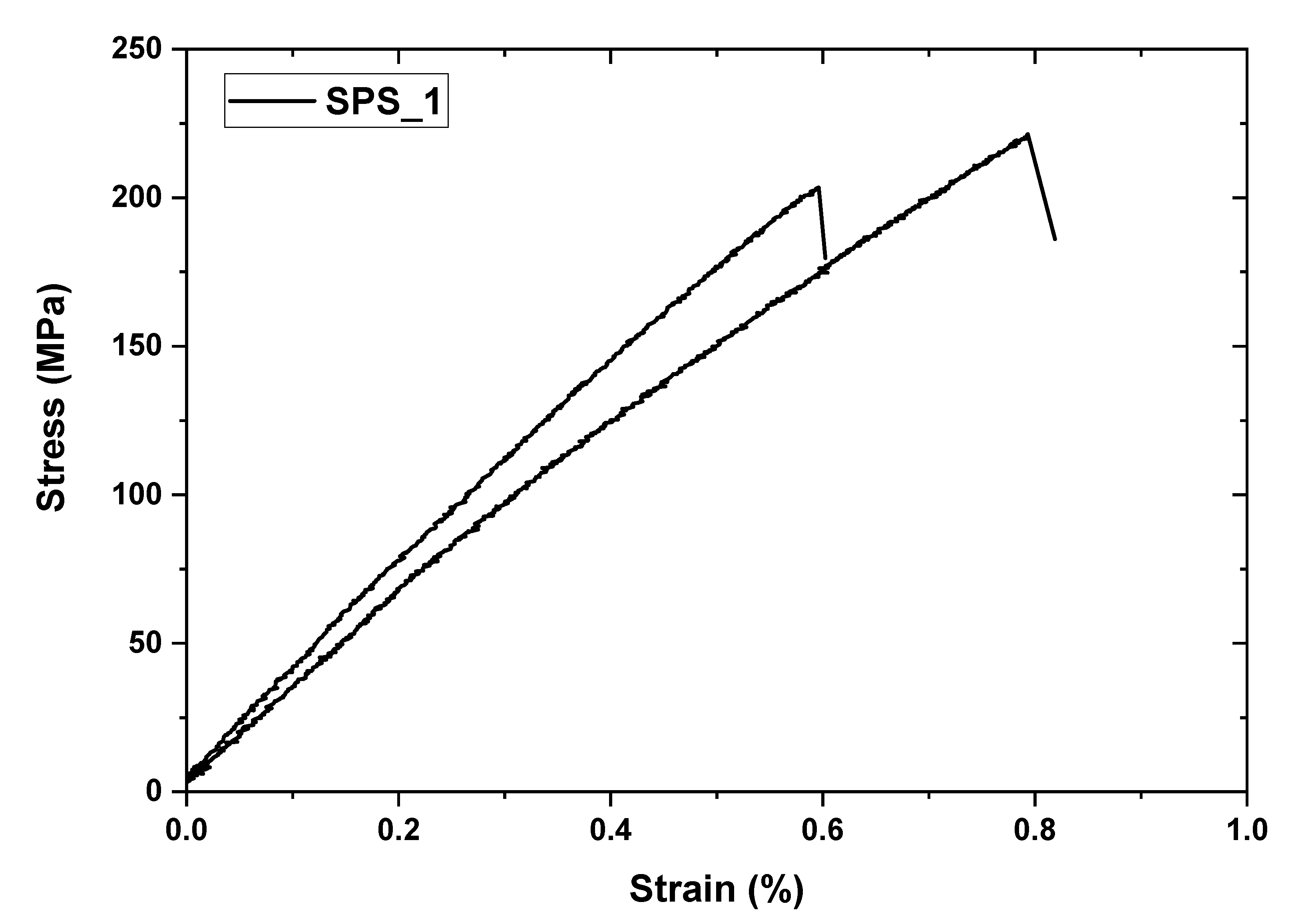
Tensile tests on NiTi alloys show three regions of interest: an elastic deformation region, a plateau region related to detwinning of martensite and, finally, a mixed elastic and plastic deformation region of martensite [25]. The room temperature stress–strain curves of the sintered NiTi alloys show decreases in the strain and stress up to failure on tension related to brittle fracture of the surface. This may enhance the behavior upon aging. The SPS sintered NiTi alloy showed transformation temperature peaks at lower temperatures due to an increase in Ni content, and the functional behavior of the SPS sample shows an SME effect with a strain recovery of 3% at a lower temperature of −50 °C.
At high temperatures, the grain boundary mobility might become higher than the pore mobility [
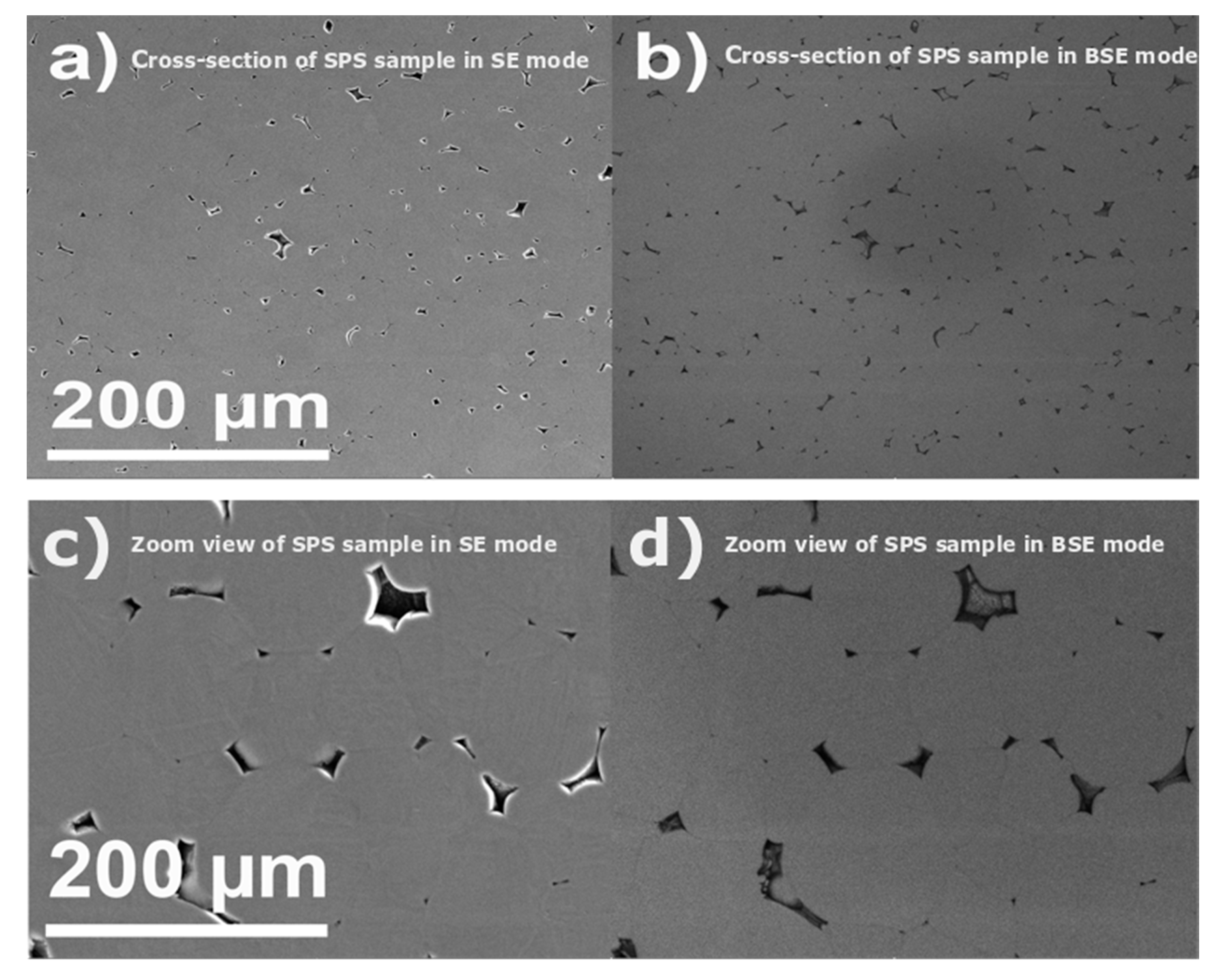
24]. It causes some pores to be detached from the grain boundary and move into the grains. As it is known, removal of the pores trapped inside the grains is harder than those attached to the grain boundaries, which results in a decrease in relative density. In other words, as the sintering process starts under high pressure and high temperature, the particles become closer, and neck formation occurs between two adjacent grains due to the diffusion phenomenon, which results in intergranular pores between NiTi particles. These kinds of pores formed during sintering have cause a pinning effect on the grain boundaries (GBs) and inhibit grain boundary movement. As the densification continued at the last stage of sintering, some of the intergranular pores shrank and were removed while some others were separated from the GBs and went into the grains, forming intragranular pores [25]. By the elimination of the intergranular pores, the GBs were freed and could move, which resulted in fast grain growth. Therefore, based on the above discussion, it can be concluded that applied pressure in the SPS method promotes the sintering and rearrangement of the particles. In addition, the pressure can act as an opponent factor against gas pressure trapped in the closed pores. Therefore, the porosities were removed more easily than those in the conventional sintering method. Some GBs and intergranular pores were formed between the particles. By raising the sintering temperature, fewer pores are detected, and grain growth occurs.
As mentioned before, the existence of the pores on the GBs pins them and retards fast grain growth. It was reported that grains might grow in a preferred crystallographic path due to uniaxial applied pressure in pressure-assisted consolidation methods such as SPS [26]. In addition, the plastic deformation mechanism of NiTi may be triggered at high temperatures [27]. In other words, the plastic yield stress of NiTi depletes with rising temperature [28,29,
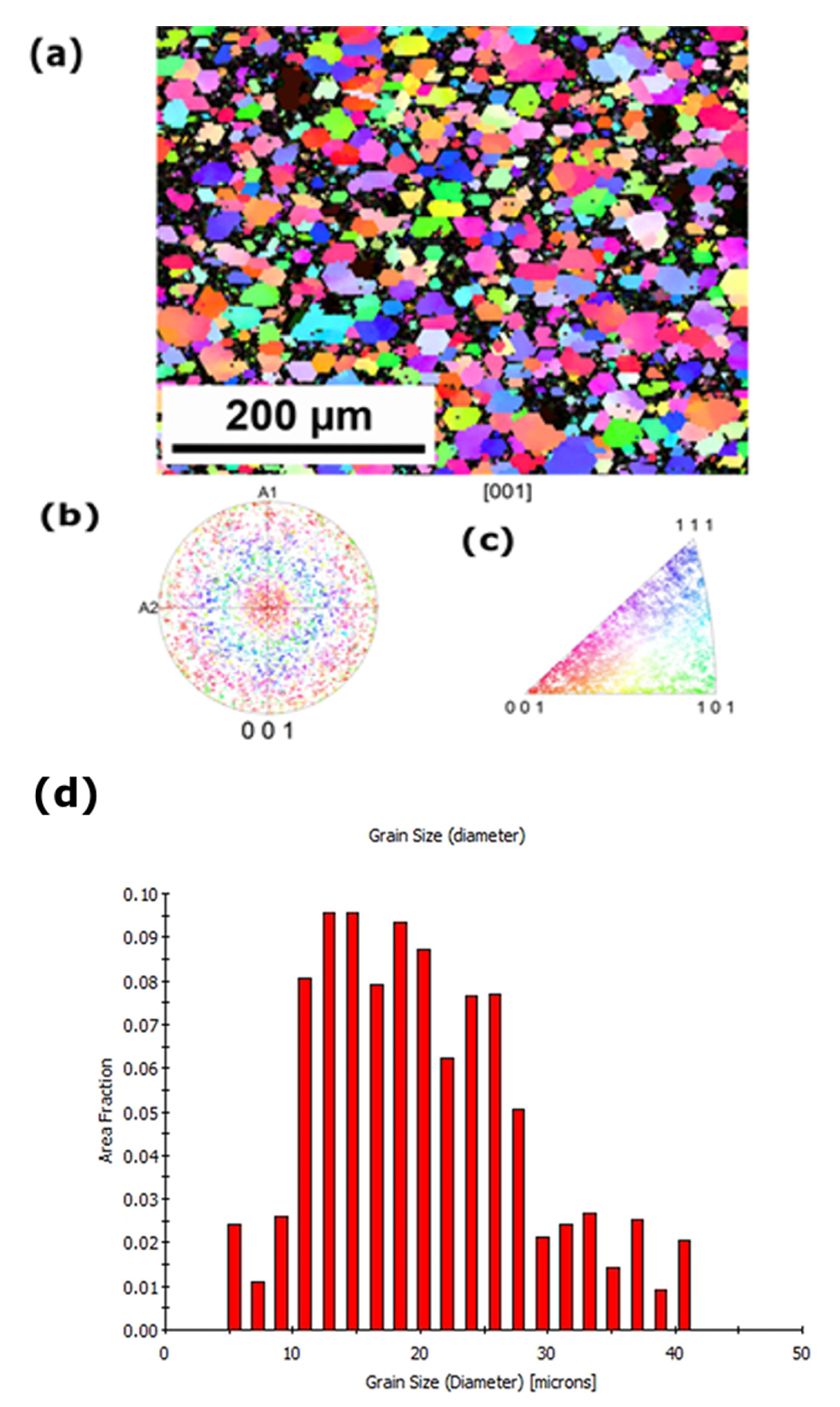
30]. Moreover, the effective pressure (Peff) on the neck or GB is usually higher than the applied pressure (P), and it depends on the relative density of the sample. Therefore, effective pressure is high enough to cause deformation in the NiTi samples, which may result in layered structures. However, this laminar structure changes to an equiaxed morphology with increasing temperature and time. This may be due to the recrystallization of the grains so that the deformed NiTi grains are replaced by the new grains that nucleate and grow until the NiTi deformed grains are consumed. For the NiTi samples spark plasma sintered at lower temperatures, extending the holding time helps further elimination and removal of porosities, whereas at high sintering temperatures, holding time has no effect on porosity removal and just increases the grain size. Nevertheless, such processing would cause grain growth, which decreases the mechanical properties of the samples. This may refer to grain growth and plastic deformation generated in the polycrystalline grains. The observation of grain size distribution—the inverse pole EBSD image (Figure 11)—reflects random distribution of grains in SPS sintered alloy. The grain size as a function of the area fraction shows that the average grain size falls within the range of 20 ± 8 µm (Figure 11d). The fragmented grains could contribute toward grain growth with fewer mechanical properties.
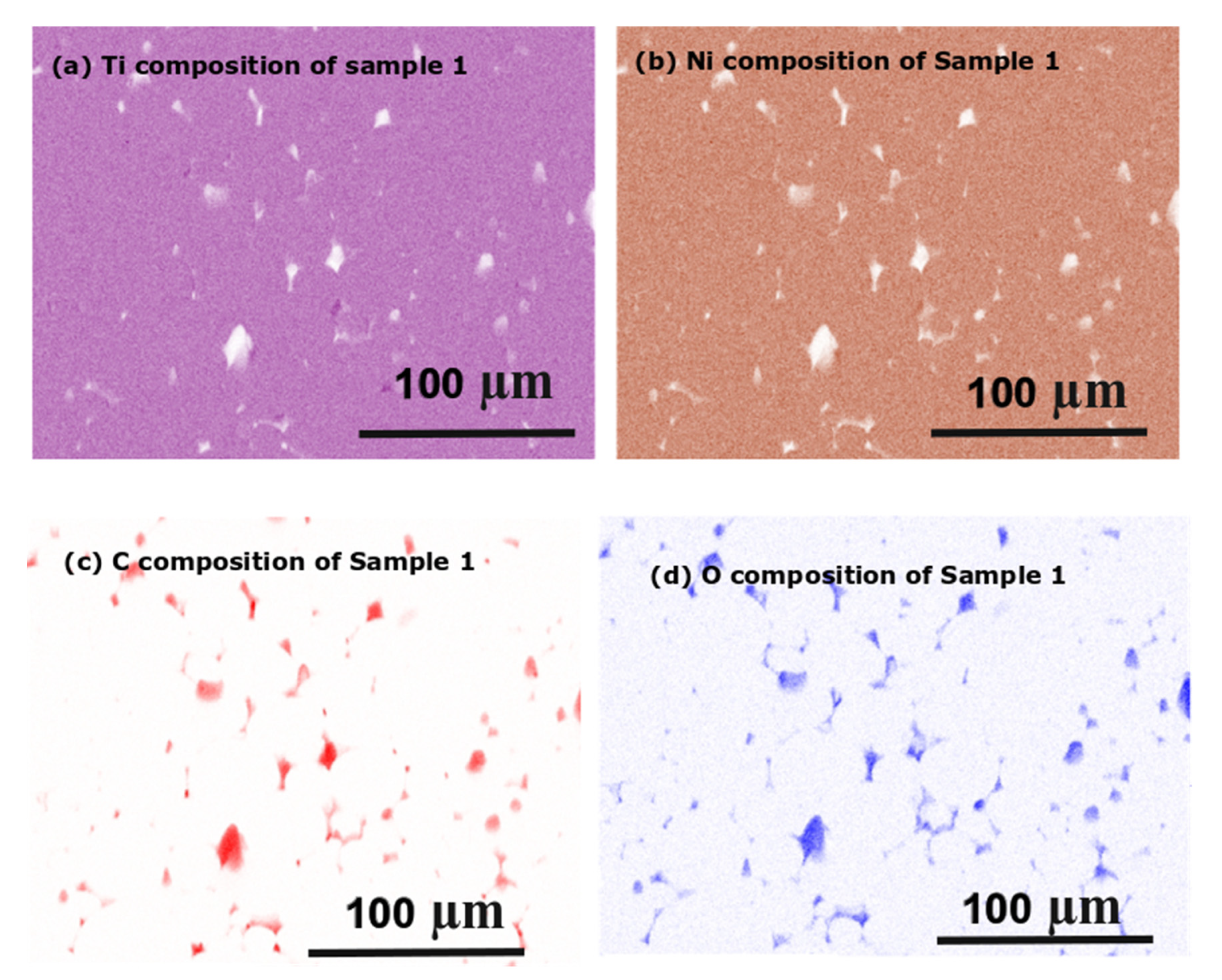
However, the overall composition of the sintered NiTi alloy for both samples shows the uniform compositions of Ti and Ni (Figure 12). The sample shows homogeneity, with the white regions showing porosity. However, the sample shows the equiatomic composition of Ti:Ni.

5. Conclusions

NiTi was successfully prepared by the SPS process and shows a shape memory effect with strain recovery of 3%. The sintering temperature combined with the DC electric charge caused plastic deformation on NiTi particles, with application of load causing the densified NiTi products. The sintered NiTi alloy exhibited compact structure with ~2.5% porosity. The grain distribution map and phase map of the NiTi alloy show the presence of the austenite phase which transforms to martensite at a cooling temperature of −22 °C. The shape memory effect was confirmed by the bending response of the NiTi alloy at a lower temperature of −75 °C; after unloading, heating induced the strain recovery. The polycrystalline grain structure arose at a higher applied load during the preparation of the NiTi alloy. This research will open up the future possibilities of composite NiTi alloys with different particle sizes.

Author Contributions

Conceptualization, resources, writing—original draft preparation S.S. and O.M. and F.P.; methodology, J.K.; L.H.: investigation, data curation, M.Š.: investigation, L.A. and I.B.: review and editing, visualization, P.Š.: supervision, project administration, funding acquisition, All authors have read and agreed to the published version of the manuscript.

Funding

Support of the research from Czech Science Foundation project 20-14114S, MEYS of the Czech Republic is acknowledged for the support of infrastructure projects FUNBIO-SAFMAT (LM2015088), LNSM (LM2018110), SOLID 21 (CZ.02.1.01/0.0/0.0/16_019/0000760), and ESS—participation of the Czech Republic—OP (CZ.02.1.01/0.0/0.0/16_013/0001794).

Institutional Review Board Statement

Not applicable.

Informed Consent Statement

Not applicable.

Data Availability Statement

Not applicable.

Conflicts of Interest

The authors declare no conflict of interest.

References

  1. Otsuka, K.; Ren, X. Physical metallurgy of Ti-Ni based shape memory alloys. Prog. Mater Sci. 2005, 50, 511–678. [Google Scholar] [CrossRef]
  2. Parvizi, S.; Hashemi, S.M.; Asgarinia, F.; Nematollahi, M.; Elahinia, M. Effective parameters on the final properties of NiTi-based alloys manufactured by powder metallurgy methods: A review. Prog. Mater Sci. 2020. [Google Scholar] [CrossRef]
  3. Morris, G.; Morris, M.A. Mechanical Alloying of Aluminium and Iron Powders to Produce Nanocrystalline Al3Fe. Mater. Sci. Forum 1992, 88–90, 529–536. [Google Scholar] [CrossRef]
  4. Samal, S. Thermal plasma technology: The prospective future in material processing. J. Clean. Prod. 2017, 142, 3131–3150. [Google Scholar] [CrossRef]
  5. Samal, S. Thermal Plasma Processing of Materials: High Temperature Applications. Ref. Modul. Mater. Sci. Mater. Eng. 2020. [Google Scholar] [CrossRef]
  6. Murakami, T.; Kitahara, A.; Koga, Y.; Kawahara, M.; Inui, Y.; Yamaguchi, M. Microstructure of Nb–Al powders consolidated by spark plasma sintering process. Mater. Sci. Eng. 1997, A239, 672–679. [Google Scholar] [CrossRef]
  7. Sang, H.Y.; Groza, J.R.; Sudarshan, T.S.; Yamazaki, K. Diffusion bonding of boron nitride on metal substrates by plasma activated sintering (PAS) process. Scr. Mater. 1996, 34, 1383–1386. [Google Scholar] [CrossRef]
  8. Shearwood, C.; Fu, Y.Q.; Yu, L.; Khor, K.A. Spark plasma sintering of TiNi nano-powder. Scr. Mater. 2005, 52, 455–460. [Google Scholar] [CrossRef]
  9. Samal, S.; Tyc, O.; Heller, L.; Šittner, P.; Malik, M.; Poddar, P.; Catauro, M.; Blanco, I. Study of Interfacial Adhesion between Nickel-Titanium Shape Memory Alloy and a Polymer Matrix by Laser Surface Pattern. Appl. Sci. 2020, 10, 2172. [Google Scholar] [CrossRef] [Green Version]
  10. Samal, S.; Kolinova, M.; Rahier, H.; Dal Poggetto, G.; Blanco, I. Investigation of the Internal Structure of Fiber Reinforced Geopolymer Composite under Mechanical Impact: A Micro Computed Tomography (µCT) Study. Appl. Sci. 2019, 9, 516. [Google Scholar] [CrossRef] [Green Version]
  11. Khademzadeh, S.; Carmignato, S.; Parvina, N.; Zanini, F.; Bariani, P.F. Micro porosity analysis in additive manufactured NiTi parts using micro computed tomography and electron microscopy. Mater. Des. 2016, 90, 745–752. [Google Scholar] [CrossRef]
  12. Velmurugan, C.; Senthilkumar, V.; Biswas, K.; Yadav, S. Densification and microstructutral evolution of spark plasma sintered NiTi shape memory alloy. Adv. Powder Technol. 2018, 29, 2456–2462. [Google Scholar] [CrossRef]
  13. Chakravarty, D.; Chokshi, A.H. Direct characterizing of densification mechanisms during spark plasma sintering. J. Am. Ceram. Soc. 2014, 97, 765–771. [Google Scholar] [CrossRef]
  14. Pellizzari, M.; Fedrizzi, A.; Zadra, M. Spark plasma co-sintering of hot work and high speed steel powders for fabrication of a novel tool steel with composite microstructure. Powder Technol. 2011, 214, 292–299. [Google Scholar] [CrossRef]
  15. Diouf, S.; Molinari, A. Densification mechanisms in spark plasma sintering: Effect of particle size and pressure. Powder Technol. 2012, 221, 220–227. [Google Scholar] [CrossRef]
  16. Obadele, B.A.; Adesina, O.S.; Oladijo, O.P.; Ogunmuyiwa, E.N. Fabrication of functionally graded 316L austenitic and 2205 duplex stainless steels by spark plasma sintering. J. Alloys Compd. 2020, 849, 156697. [Google Scholar] [CrossRef]
  17. Shevtsova, L.; Sameyshcheva, T.; Terentyev, D.; Malyutina, I.; Larichkin, A.; Malikov, V. Effect of plastic deformation of the initial components and particle size reduction on the structure and properties of the PN85YU15-Ni composite material produced by spark plasma sintering. Appl. Mech. Mater. 2015, 788, 151–156. [Google Scholar] [CrossRef]
  18. Pouchly, V.; Maca, K.; Shen, Z. Two-stage master sintering curve applied to two-step sintering of oxide ceramics. J. Eur. Ceram. Soc. 2013, 33, 2275–2283. [Google Scholar] [CrossRef]
  19. McNamara, K.; Butler, J.; Gandhi, A.A.; Tofail, S.A.M. Powder Metallurgical Processing of NiTi Using Spark Plasma Sintering. Compr. Mater. Finish. 2017, 3, 336–346. [Google Scholar] [CrossRef]
  20. Salvetr, P.; Dlouhý, J.; Školáková, A.; Průša, F.; Novák, P.; Karlík, M.; Haušild, P. Influence of Heat Treatment on Microstructure and Properties of NiTi46 Alloy Consolidated by Spark Plasma Sintering. Materials 2019, 12, 4075. [Google Scholar] [CrossRef] [PubMed] [Green Version]
  21. Zhang, Z.; Frenzel, J.; Neuking, K.; Eggeler, G. On the reaction between NiTi melts and crucible graphite during vacuum induction melting of NiTi shape memory alloys. Acta Mater. 2005, 53, 3971–3985. [Google Scholar] [CrossRef]
  22. Ren, X.; Miura, N.; Zhang, J.; Otsuka, K.; Tanaka, K.; Koiwa, M.; Suzuki, T. A comparative study of elastic constants of Ti− Ni-based alloys prior to martensitic transformation. Mater. Sci. Eng. A 2001, 312, 196–206. [Google Scholar] [CrossRef]
  23. Xue, D.; Zhou, Y.; Ren, X. The effect of aging on the B2−R transformation behaviors in Ti−51at%Ni alloy. Intermetallics 2011, 19, 1752–1758. [Google Scholar] [CrossRef]
  24. Jones, N.G.; Dye, D. Influence of applied stress on the transformation behaviour and martensite evolution of a Ti−Ni−Cu shape memory alloy. Intermetallics 2013, 32, 239–249. [Google Scholar] [CrossRef]
  25. Liu, B.; Huang, S.; Chen, L.; Van Humbeeck, J.; Vleugels, J. Rapid synthesis of dense NiTi alloy through spark plasma sintering of a TiH2/Ni powder mixture. Mater. Lett. 2017, 191, 89–92. [Google Scholar] [CrossRef]
  26. Ghasali, E.; Baghchesaraee, K.; Orooji, Y. Study of the potential effect of spark plasma sintering on the preparation of complex FGM/laminated WC-based cermet. Int. J. Refract. Met. Hard Mater. 2020, 92, 105328. [Google Scholar] [CrossRef]
  27. Devaraj, S.; Sankaran, S.; Kumar, R. Influence of spark plasma sintering temperature on the densification, microstructure and mechanical properties of Al-4.5 wt.%Cu alloy. Acta Met. Sin 2013, 26, 761–771. [Google Scholar] [CrossRef] [Green Version]
  28. Marnier, G.; Keller, C.; Noudem, J.; Hug, E. Functional properties of a spark plasma sintered ultrafine-grained 316L steel. Mater. Des. 2014, 63, 633–640. [Google Scholar] [CrossRef]
  29. Hu, Z.-Y.; Zhang, Z.-H.; Cheng, X.-W.; Wang, F.-C.; Zhang, Y.-F.; Li, S.-L. A review of multi-physical fields induced phenomena and effects in spark plasma sintering: Fundamentals and applications. Mater. Des. 2020, 191, 108662. [Google Scholar] [CrossRef]
  30. Deng, Y.-M.; Edwards, K.L. The role of materials identification and selection in engineering design. Mater. Des. 2007, 28, 131–139. [Google Scholar] [CrossRef]
Figure 1. Surface features of the gas-atomized NiTi powder. (a) SEM image of the particles; (b) zoom view of the particles; (c) cross-section image of the particle shows no porosity within the particle; (d) particle size distribution (davg: 50 µm).
Applsci 11 01802 g001
Figure 2. Sintering parameters of the spark plasma sintering sample. Temperature, force versus time for NiTi sample at 900 °C for 95 kN load with height reduction and current. The section was divided into four segments (I–IV).
Applsci 11 01802 g002
Figure 3. Surface morphology of the spark plasma sintered NiTi alloy. (a) Cross-section image of the sintered spark plasma sintered (SPS) NiTi alloy in superelasticity (SE) mode; (b) cross-section image of the sintered SPS NiTi alloy in Back Scatter Electron (BSE) mode; (c) zoom view of the cross-section image of sample 1 shows porosity along joining of the particles in SE mode; (d) zoom view of the cross-section image of sample 1 in BSE mode.
Applsci 11 01802 g003
Figure 4. Differential Scanning Calorimetry (DSC) analysis of the NiTi powder, SPS sample (sample 1).
Applsci 11 01802 g004
Figure 5. Electron Back Scatter Diffraction (EBSD) pattern of the NiTi alloy. (a) SE image of the cross-section; (b) inverse pole figure (IPF) map overlayed on a greyscale confidence index map of sample 1; (c) phase map overlayed on a greyscale confidence index map of sample 1—only austenite (red color) was observed; (d) colorized legend for phase.
Applsci 11 01802 g005
Figure 6. Internal volumetric scan of the sintered NiTi sample. (a) µCT of the sample 1 shows inner voids as dots; (b) 3D image of the sample; (c) cross-cut of the sample.
Applsci 11 01802 g006
Figure 7. Thermo-mechanical Analysis (TMA) study of the sintered sample of NiTi alloy at constant loads of 200 and 500 mN for sample 1; temperature versus displacement and coefficient of thermal expansion(CTE).
Applsci 11 01802 g007
Figure 8. Stress versus strain for the NiTi alloy at bending during cooling and heating cycles of sample 1; stress versus strain in loading, unloading and heating to initial point as shape memory effect.
Applsci 11 01802 g008
Figure 9. Sintered NiTi alloy at a constant stress of 300 MPa Sample 1 as frequency Tan (delta) storage modulus (MPa) and loss moduli (GPa) as the function of cooling to the heating range of temperature (−150 to +100 °C).
Applsci 11 01802 g009
Figure 10. Tensile behavior of sample 1 shows stress versus strain curve.
Applsci 11 01802 g010
Figure 11. EBSD inverse pole and pole figure orientation maps and [001] pole figures of the SPS sample from the selected area shows grain size of 20 ± 8 µm. (a) Selected area grain orientation; (b) inverse pole; (c) pole figure of sample 1; (d) grain size versus area fraction for SPS sample.
Applsci 11 01802 g011
Figure 12. Elemental composition of sample 1: (a) Ti; (b) Ni; (c) C; (d) O (carbon and oxygen contents found in pore region).
Applsci 11 01802 g012
Publisher’s Note: MDPI stays neutral with regard to jurisdictional claims in published maps and institutional affiliations.

