Article

A Bioinspired Humanoid Foot Mechanism

1
Faculty of Engineering, University of Nottingham, Nottingham NG8 1BB, UK
2
IRCCS Neuromed, Via dell’Elettronica, 86077 Pozzilli (IS), Italy
3
Department of Medicine and Health Science, University of Molise, 86100 Campobasso (CB), Italy
*
Author to whom correspondence should be addressed.
Appl. Sci. 2021, 11(4), 1686; https://doi.org/10.3390/app11041686
Submission received: 21 January 2021 / Revised: 8 February 2021 / Accepted: 9 February 2021 / Published: 13 February 2021
(This article belongs to the Special Issue Innovative Robot Designs and Approaches)

Abstract

:
This paper introduces an innovative robotic foot design inspired by the functionality and the anatomy of the human foot. Most humanoid robots are characterized by flat, rigid feet with limited mobility, which cannot emulate the physical behavior of the foot–ground interaction. The proposed foot mechanism consists of three main bodies, to represent the heel, plant, and toes, connected by compliant joints for improved balancing and impact absorption. The functional requirements were extracted from medical literature, and were acquired through a motion capture system, and the proposed design was validated with a numerical simulation.

1. Introduction

Humanoid robotics has fascinated and challenged scientists for decades [1]. The design of humanoid robots has evolved from the serial design of the first humanoids, such as WABOT (WAseda roBOT) [2], to more refined architectures [3,4,5,6,7,8,9,10,11,12]. However, despite decades of research, the mobility of most of these robots is still limited to the legs, arms, hands, and head only, with very few examples including torso [10] and foot [13,14,15,16,17,18,19,20,21,22,23] mobility, despite the feet and torso playing a key role in human motion [24]. The reduced mobility of humanoid robots in those regions hinders their capability to achieve balance and to perform complex dynamic tasks. Human foot architecture is characterized by three main segments—namely the heel, mid-foot, and toes—that fulfill distinct roles during bipedal locomotion [25].
However, several humanoid robots use flat, one-segment feet [2,3,4,5,6,7,8,9,10,11,12]. Some famous examples include Honda’s ASIMO (Advanced Step in Innovative Mobility) [3], the iCub design and its variants from the Italian Institute of Technology [7], and Softbank Robotics NAO [9]. Several research groups have tried to improve the foot performance by compensating a limited mechanical design with an enhanced sensing/control capability, which can be obtained by adding force/pressure sensors to the plant of the foot [26,27,28,29,30], with mixed results. Others kept a one-segment design, but moved from a flat rigid sole to a compliant one [13,14,15], obtaining significant results and increased performance (e.g., Boston Dynamics’ Atlas [14]). Soft options have been also explored through designs with a highly elastic foot sole directly connected to the ankle joint [16].
Some research groups investigated the possibility of using two-segment feet, with a heel segment and a toe segment [16,17,18,19,20]. Foot designs with three segments have been proposed to better mimic human-like motion [21,22], but are usually characterized by active mechanisms that require a complex control and motion coordination with the rest of the body [21], or by planar rigid-body mechanisms [22] that achieve balance through spring-loaded joints only. While successful, the lack of compliance in these three-segment designs limits their behavior when obstacles introduce 3D torques and loads.
In this paper, an innovative passive mechanism for robotic feet is presented, which is able to adapt to the environment without the need of external actuation thanks to joint elasticity. First, the mobility requirements to achieve human-like motion are extracted from medical literature and experimental gait analysis using a motion capture system. Then, the proposed design is introduced, along with its main characteristics and technical details. The foot mechanism is validated through numerical simulation with both Finite Element Analysis (FEA) and Multibody Dynamics, and a prototype is manufactured with 3D printing in order to prove the feasibility of the proposed mechanism on a range of terrains and obstacles.

2. Materials and Methods

2.1. Requirements for Humanoid Foot Mechanisms

In order to obtain the mobility requirements for humanoid foot mechanisms, the human gait was analyzed in terms of absolute and angular motion [31,32,33,34,35] looking retrospectively at clinical outcomes from patients who outcome a healthy gait cycle. In accordance with the medical standards, a variation of the Davis protocol [31]—with a marker on the second metatarsus instead of fifth—was used to acquire the motion of 11 subjects (details in Table 1) over 10 distinct gait sessions of four walking steps each. The motion was acquired through a VICON Motion Capture system, with the following retroreflective marker set configuration and alignment (Figure 1 and Figure 2):
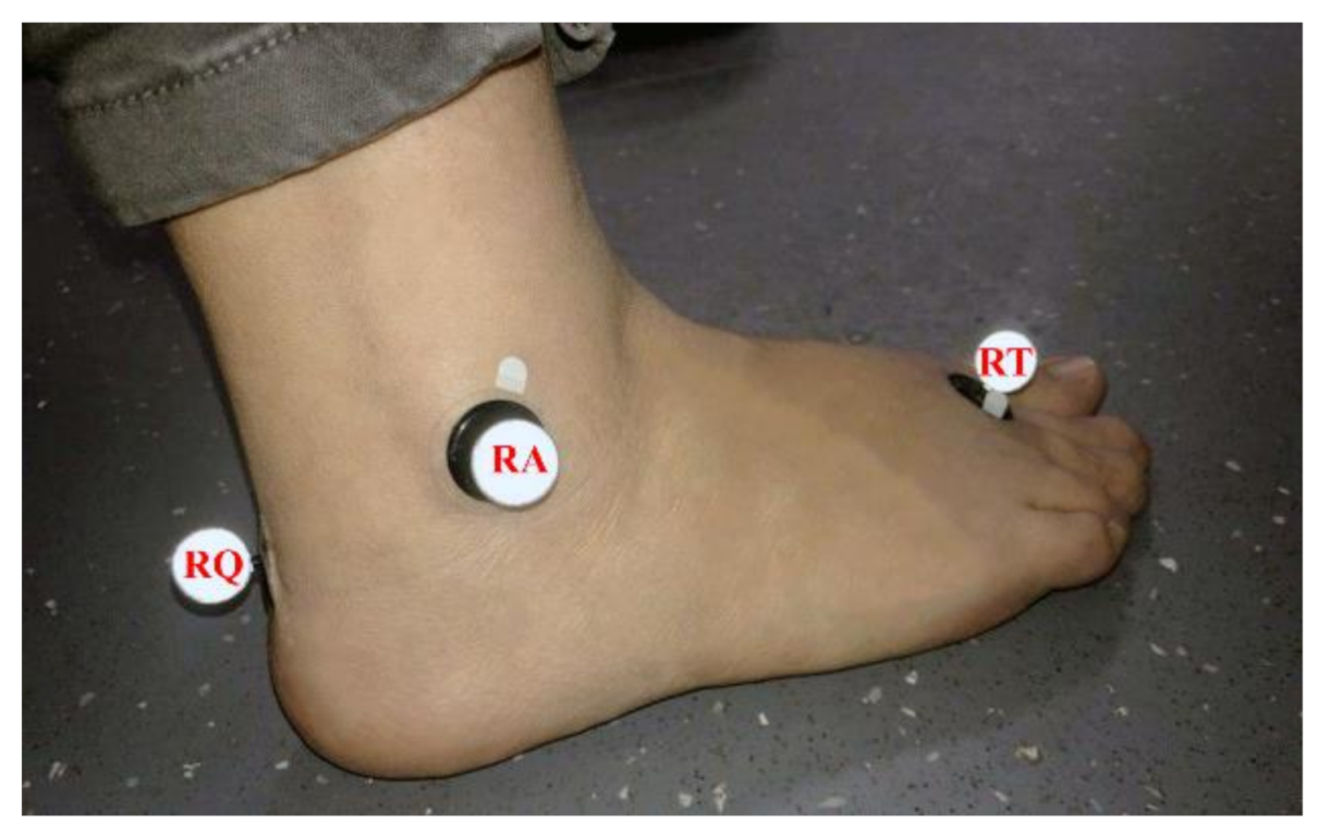
  • RA, right ankle marker: Placed at the level of the lateral malleolus;
  • RT, right toe marker: Placed on the lateral aspect of the foot at the second metatarsal head;
  • RQ, right heel marker: Positioned so that the heel–toe marker vector is parallel to (but offset from) the sole of the foot, and is aligned with the foot progression line (i.e., the line from the ankle center to the space between the second and third metatarsal heads).
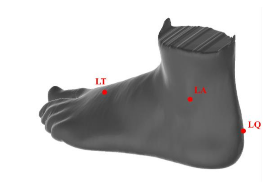
  • LA, left ankle marker: Placed at the level of the lateral malleolus;
  • LT, left toe marker: Placed on the lateral aspect of the foot at the second metatarsal head;
  • LQ, left heel marker: Positioned so that the heel–toe marker vector is parallel to (but offset from) the sole of the foot, and is aligned with the foot progression line.
The BTW Gaitlab software (BTS Bioengineering Corp., Quincy, MA, USA) [32] was used for the data processing, according to the following steps:
  • For each four-step acquisition, each step of the gait was isolated.
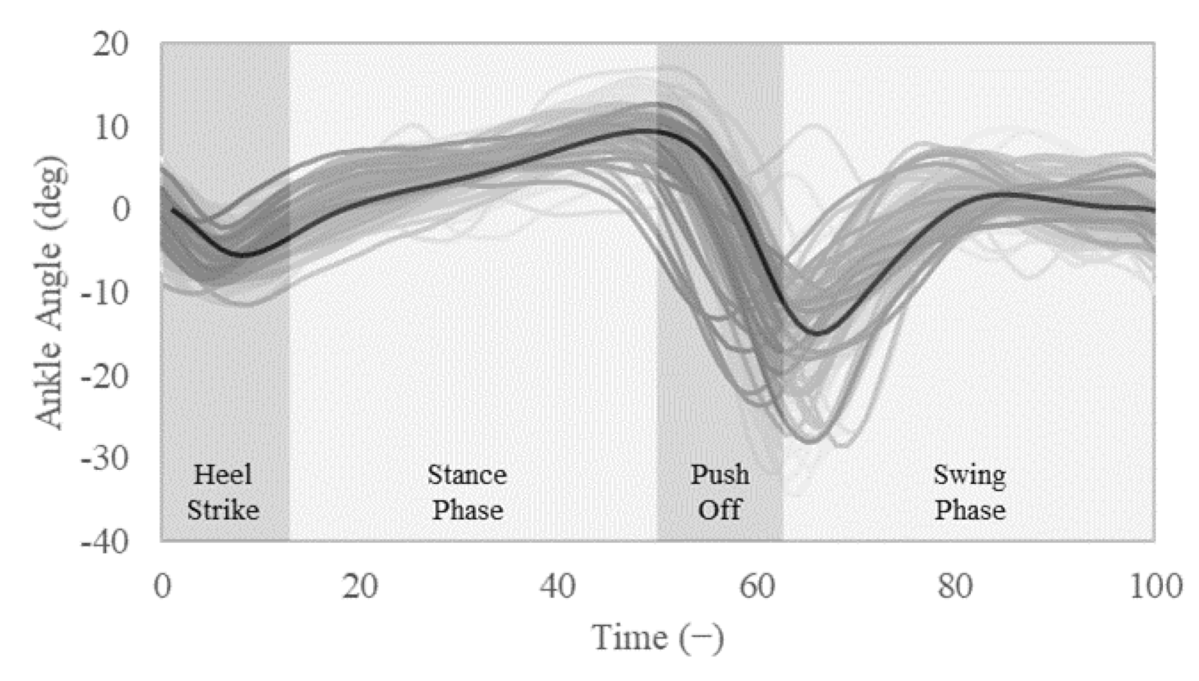
  • The time of each single step was normalized in a 0 to 100 scale, in which 0 represents the beginning of the step cycle (stance with dual foot support) and 100 represents the end of that step cycle, and corresponds to the beginning of the following step.
  • The normalized step data were filtered and compared for all of the acquisitions in order to remove out-of-phase outliers, whereas the outliers on the ankle angle acquired value were left in the graph in Figure 3 for completeness, but were removed from further calculations.
  • The remaining dataset was used to obtain a normalized average gait in terms of ankle angle, which is illustrated by the black line in Figure 3.
The resulting average angular displacement for the whole motion is approximately 25 degrees, compared to a peak value of 45 degrees of the ankle angular displacement for some acquisitions. By expressing the angular motion range of the heel part of the foot, the values in Figure 3 identify all of the possible foot configurations in which the foot must be in stable contact with the ground in order to support the body, and will be used both for dimensioning and simulating the proposed humanoid foot mechanism design.

2.2. An Underactuated Humanoid Foot Mechanism

The proposed foot mechanism aims to enhance robot mobility and efficiency by enabling body support in all of the stances acquired in Section 2. In order to do so, a three-segment design was considered, based on the diagram in Figure 4. During the gait, the foot motion is ruled by four main centers of rotation, which correspond to the ankle joint, the heel bone (or calcaneus), the navicular tuberosity, and the metatarsophalangeal (MTP) joint, as shown in Figure 4. The first segment of the foot can be associated to the calcaneus-talus complex, which includes the heel and ankle, and can be approximated to a rigid body. The motion of the central segment of the foot is enabled by the active stiffening behavior of the intrinsic foot muscles in the plantar arches, which connect the calcaneus to the MTP joint. The plantar fascia and several ligaments support the plantar arches, which store mechanical energy during weight bearing by deforming. This behavior can be reproduced with the elasticity of a compliant body. The motion of the last segment of the foot can be approximated to a flexion/extension movement of the toes, which rotate around the MTP joint and the interphalangeal joints. The MTP joint is usually described as a condyloid joint, while the interphalangeal joints resemble revolute joints.
In order to replicate the behavior of the human foot, a new compliant foot mechanism based on the kinematic scheme in Figure 5 is here presented. The proposed mechanism is based on a compliant mechanism in the plant, which can be approximated with an RRPR (revolute-revolute-prismatic-revolute) architecture, with revolute joints in points B, C, and D, and a link of varying length between B and D. Furthermore, a second compliant mechanism is added in the MTP joint in point E, with a rigid revolute joint controlled by a torsional spring.
The mechanism works mainly on the sagittal plane, even if the compliant part can be designed to balance 3D loads as well. When analyzing the planar behavior of the proposed foot design, its degrees of freedom can be evaluated from its rigid mechanism equivalent with the Chebychev-Grübler-Kutzbach criterion as two, controlled respectively by the plantar compliant element and by the torsional spring of the MTP joint. An exemplar design of the proposed foot mechanism is shown in Figure 6.

3. Results

3.1. Simulation and Results

The behavior of the humanoid foot was checked through a nonlinear, dynamic study using FEA. Iterative schemes to solve Equation (1) through the Newton–Raphson method (NR), already integrated in the software, were used for each node (i).
M t + Δ t U i + C t + Δ t U i +   t + Δ t K i   t + Δ t Δ U i   =     t + Δ t R   t + Δ t F i 1
where:
  • [M] = Mass matrix of the system;
  • [C] = Damping matrix of the system;
  • t + Δ t [ K ] ( i ) = Stiffness matrix of the system;
  • t + Δ t [ R ] = Vector of externally-applied nodal loads;
  • t + Δ t [ F ] ( i 1 ) = Vector of internally-generated nodal forces at iteration (i−1);
  • t + Δ t [ Δ U ] ( i ) = Vector of incremental nodal displacements at iteration (i);
  • t + Δ t { U } ( i ) = Vector of total displacements at iteration (i);
  • t + Δ t { U } ( i ) = Vector of total velocities at iteration (i);
  • [ M ] t + Δ t { U } ( i ) = Vector of total accelerations at iteration (i).
In nonlinear static analysis, equations have to be solved at any time step tt. Because the internal nodal forces tt{F}(i−1) depend on the nodal displacements at time tt, ttU](i), an iterative method must be used to find a converging solution. The above-mentioned iterations have several methodologies in place. The NR scheme was used for this simulation. Within this method, the tangential stiffness matrix is formed and decomposed in a certain step in every iteration. The NR method using Newmark integration is used because it has a high rate of convergence, and is quadratic. However, each iteration generates and decomposes the tangential rigidity, which is prohibitively costly for larger models. Thus, a different iterative approach may be advantageous.
The humanoid foot was placed above a solid body, simulating the ground. The ground was fixed, giving it 0 degrees of freedom. A gravity of 9.807 m/s2 was set, acting on the entire assembly. The temperature loads were included, setting a constant temperature of 298 Kelvin. The mean angular displacement of the ankle acquired from the subject was used as the input motion for the nonlinear dynamic simulation. The definition of the time curve for the angle displacement application was set to simulate the mean step duration for 0.63 s, using a force control technique. The input given to the simulation was extracted by the gait analysis data, and it corresponds to the average gait of Figure 3. The input motion was applied to the ankle joint axis, which is highlighted in blue in Figure 7.
The humanoid foot is composed of four bodies, three of which are in ABS rigid plastic (Table 2), and the middle of which is set to thermoplastic polyurethane (TPU) for his flexible mechanical properties, simulating the muscle part. Another key component is the spring—shown in Figure 8—in the forefoot, which passively improves the ability of the foot to adapt to the ground; the spring was modelled with a 2 mm diameter, five coils, and an 8 mm length, and alloy steel was chosen as material in order to simulate a commercial part. After setting all of the required parameters, a mesh was generated with the parameters in Table 3 to perform the FEA.
Figure 9 shows the FEM nonlinear dynamic analysis stress results computed by the use of the Von Mises formulation. A maximum value of 2.57 × 10⁶ N/m2 is observed in the upper part of the rigid midfoot, next to the connection to the compliant body. The maximum value is significantly smaller than the yield limit of the material, thus validating the proposed humanoid foot for an average walking gait. The behavior of the impact of the foot on the ground is obtained by applying the mean angle displacement taken from the analyzed subjects (see Section 2). The results can be observed in the step-by-step effect of the load on the different bodies of the humanoid foot, as is shown in the linear displacement distribution reported in Figure 10:
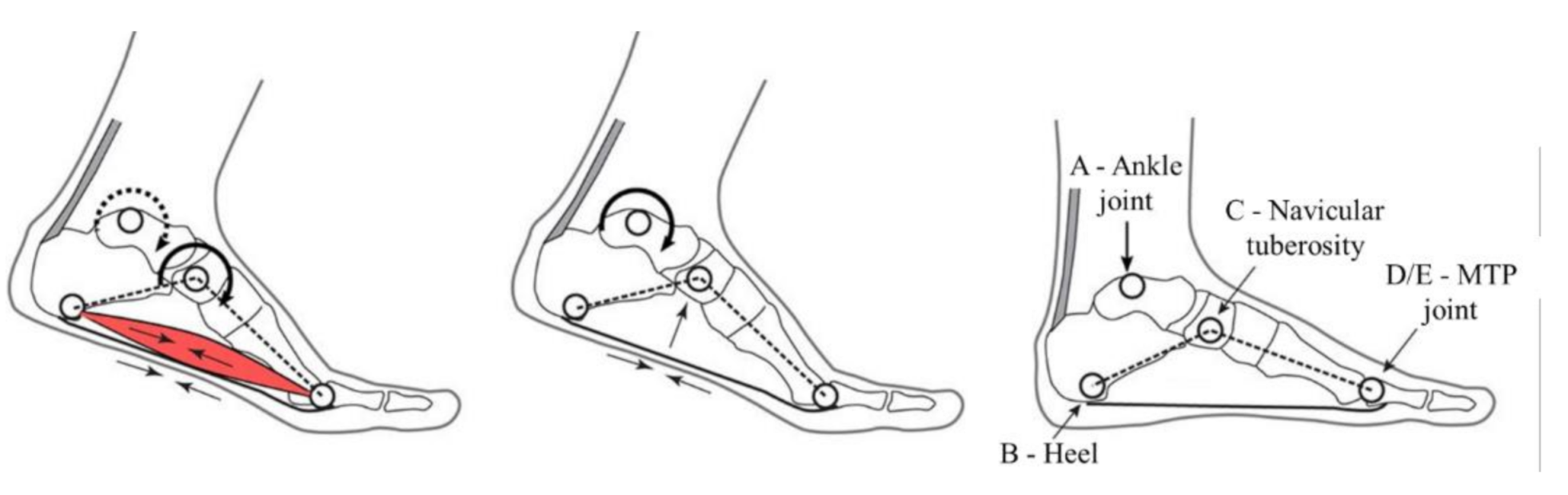
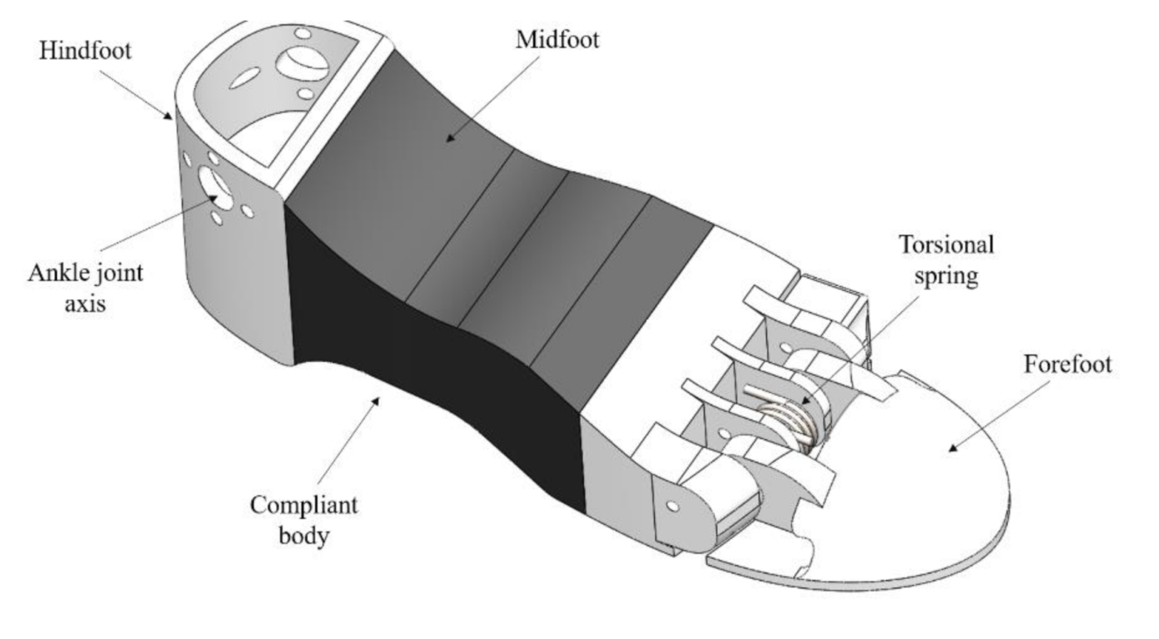
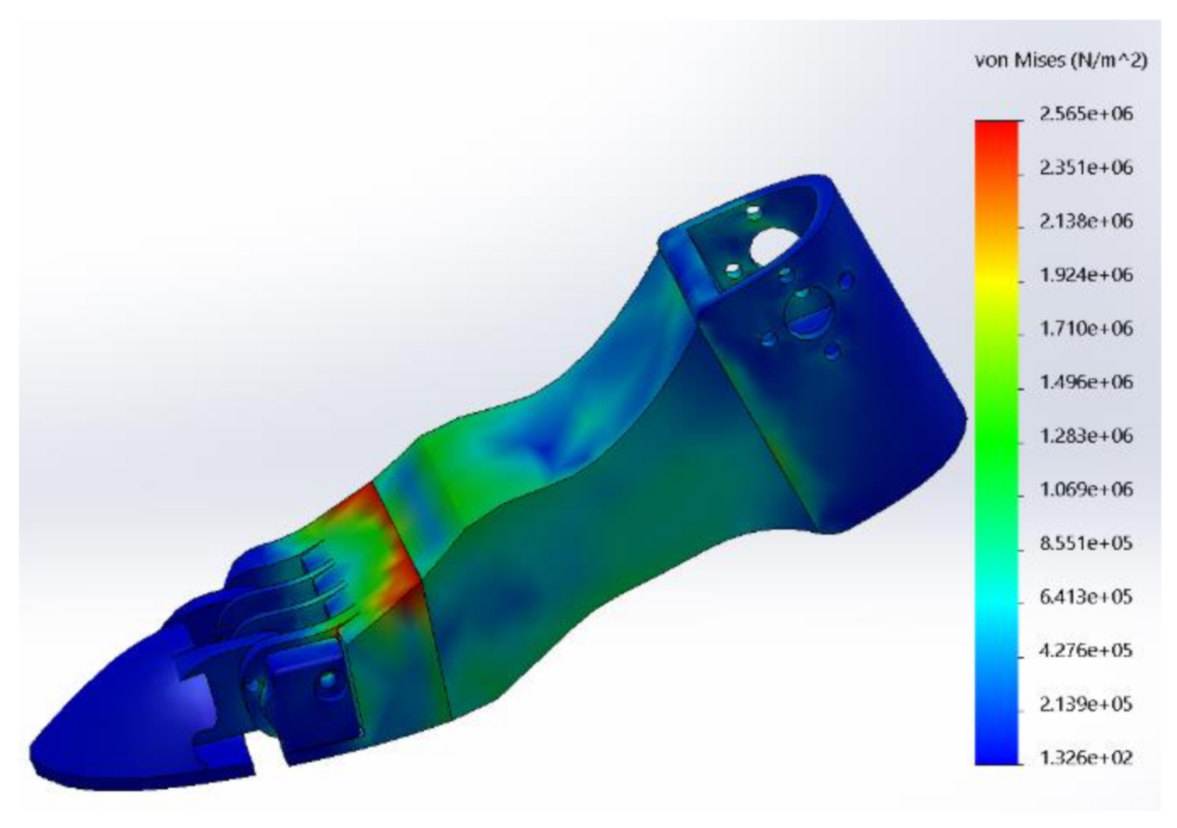
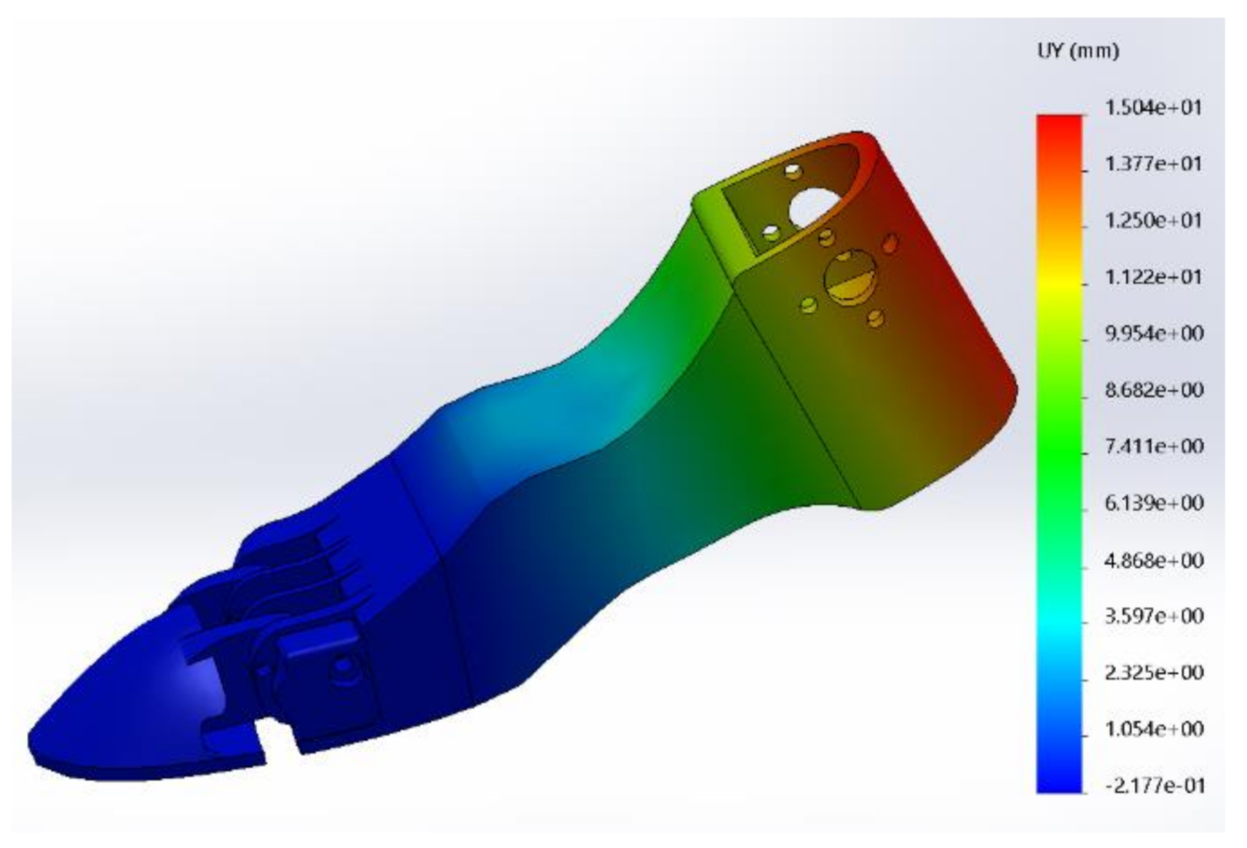
  • Starting from the rigid body of the hindfoot, the angular displacement is applied to the ankle joint. The hindfoot is connected to the flexible body of the midfoot, which starts to deform.
  • When the angular displacement causes the foot to hit the ground, the midfoot is characterized by a stress concentration in the upper part, as per Figure 9.
  • The arc bottom part of the foot is loaded with a maximum tension of 1.57 × 10⁶ N/m2, behaving as the human foot muscle when stepping.
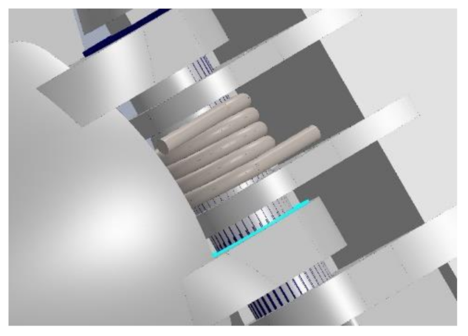
  • The spring connecting the two bodies of the forefoot is stretched. This helps the foot to adapt to the ground, and the potential energy of the spring restores the neutral ‘flat’ position when the contact is released.
These results validate the behavior of the proposed humanoid foot, showing that it acts similarly to the human foot in terms of stress while walking. Furthermore, the results prove that the proposed design can safely withstand the loads associated with an average human gait, including the impact of the foot on the ground.

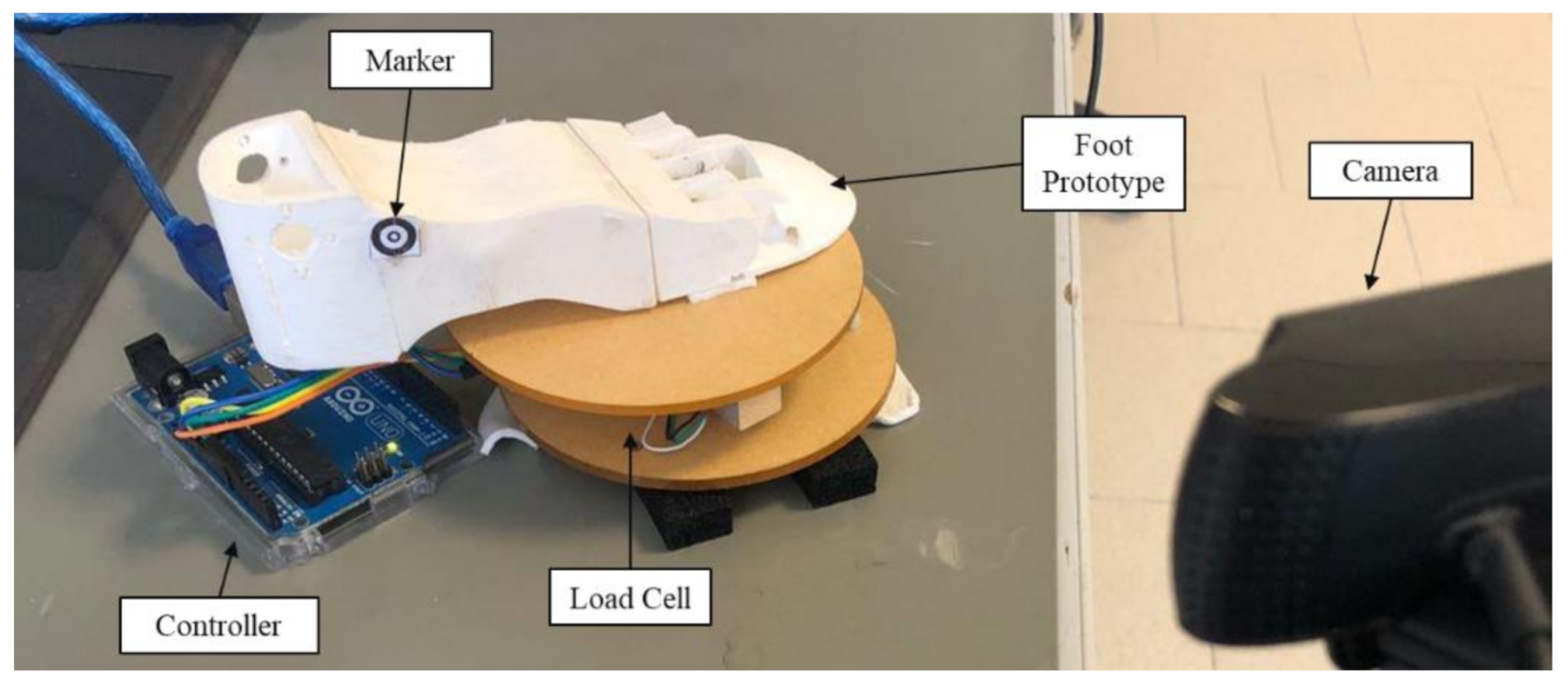
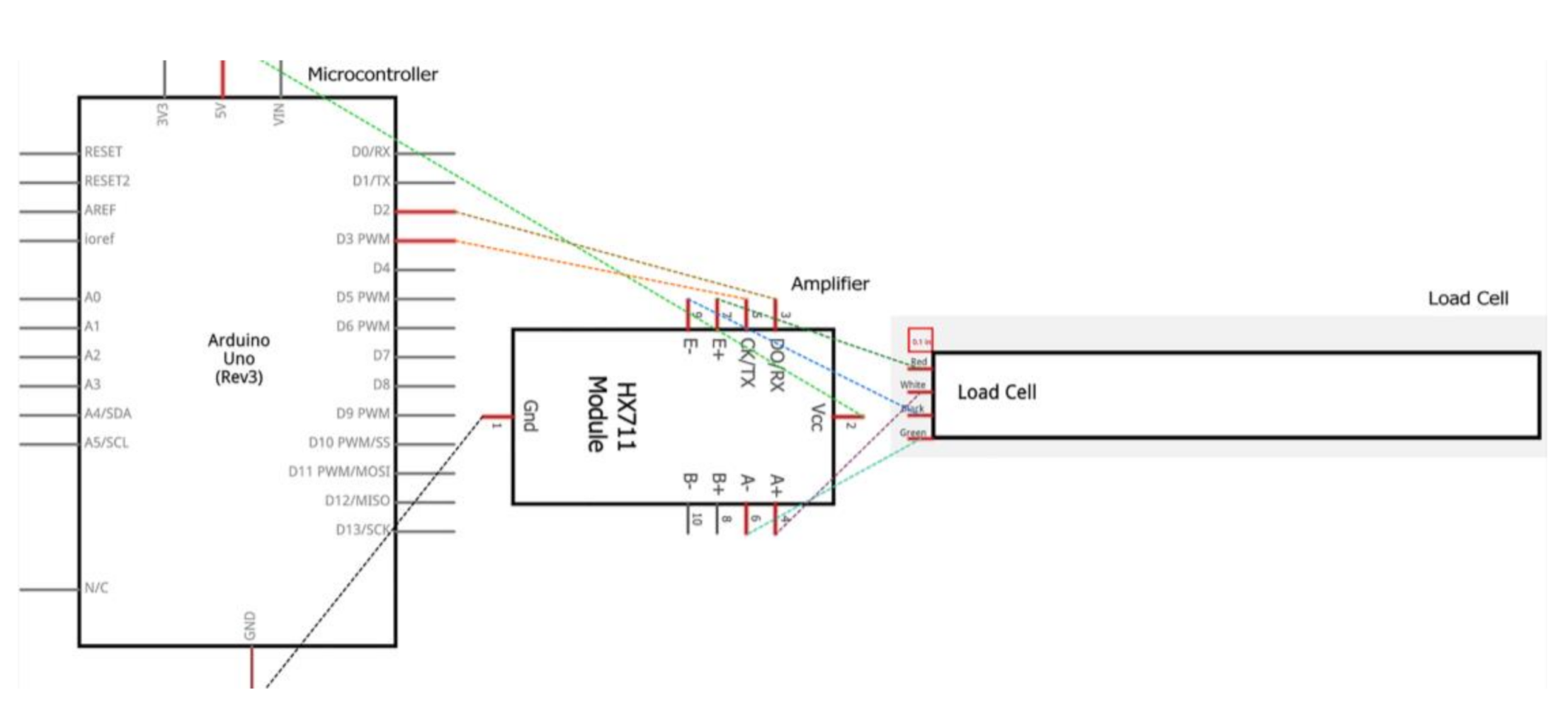
3.2. Experimental Tests

Due to the promising simulation results, a preliminary prototype was built at the Biomechatronics Lab of IRCSS Neuromed in Pozzilli, Italy. The prototype is composed of six parts: five were manufactured by 3D printing, using the rapid prototyping techniques explained by Cafolla et al. [36], whereas the last one is a commercial mechanical component. The printing materials were chosen from among a wide variety of commercial resins and plastics, in order to ensure the desired foot behaviour: the four rigid bodies were printed in PLA filament; the flexible component, representing the midfoot of the mechanism, was manufactured using a TPU filament with properties matching the ones of the FEA. The properties of both materials are reported in Table 4, for reference. Different infill percentages and patterns were tested for the midfoot, and the final infill was selected for its optimal TPU stiffness. Both the value of the infill and the 3D support pattern with which the infill was printed were optimized according to the surface curve of the compliant component through an FEA with constrained motion (as per the acquired gait).
The correct relative positioning of the components is defined by male and female rectangular pins. Then, the components are locked together with interlocking shapes. Additionally, epoxy glue was added to the coupled surfaces in order to improve the strength of the connection, as it is the most loaded component of the system, as shown in Figure 9. The assembly of the entire foot is shown in Figure 11. The prototype of the humanoid foot is composed of a rigid hind foot, a flexible mid foot, and a rigid forefoot, which is made of three 3D printed rigid parts, namely the connection pin, the sole and the toe, and a commercial part, the spring. The prototype was scaled down from human size in order to fit a service humanoid robot design [10,11,12], and thus the whole foot can fit into a box of (146 × 52 × 41) mm; it weighs 57.80 g.
As a preliminary test, the adaptability of the foot to different step heights was tested. Figure 12 and Figure 13 show the foot adapting to a 22 mm high step and a 54 mm high step, respectively. The combination of the forefoot spring and the compliant midfoot actions allow the proposed foot design to balance on step heights up to approximately 35% of the length of the foot.
Further experimental tests were conducted in order to measure the reaction force between the foot and the ground, and to validate the FEA results of Figure 9 and Figure 10. By using the experimental setup shown in Figure 14, a load cell was calibrated with a set of calibration weights (accuracy 1%) before the experimental test, and was then used to measure the force, according to the scheme in Figure 15. A camera was used to measure the foot motion by tracking the marker in Figure 14 through the Kinovea software. By using the real dimension of the marker, i.e., 10 × 10 mm, the motion in pixels is converted to real-world one with a semi-automated tracking process, which has an estimated accuracy of 5% (measured through a checkerboard calibration).
A 1-second stance cycle was manually reproduced, moving according to the motion in Figure 16, which was measured with the camera during the experiment. During the load cycle, the marker moved 9.5 mm, with a comparable motion to the corresponding point in the analysis in Figure 10. The action of the foot on the ground, measured with the load cell, was reported in Figure 17.
The vertical ground reaction force applied to the foot is bimodal, with an initial impact peak, followed almost immediately by a propulsive peak as the foot pushes off against the ground. In a conventional humanoid robotic foot, this impulsive force is transmitted fully to the ankle, with the risk of disrupting the robot’s balance. Conversely, the proposed foot is able to dampen this impact through the spring and the compliant body, significantly reducing the stress on the ankle joint.
Hall [37] and Munro [38] report that for a gait speed between 3.0 m/s to 5.0 m/s, the impact forces range from 1.6 to 2.3 times the body weight, and the propulsive forces range from 2.5 to 2.8 times the body weight. In order to compare their results to the experimental ones, an overall body weight of 3.6 kg was estimated from humanoid robots of similar sizes and proportions [10]. The acquired results, reported in Figure 16, are in a comparable range (6% error on displacement) of the FEA simulation, and show a comparable behaviour to that of the human locomotion system, with a propulsive peak of approximately 3.0 times body weight.

4. Discussion and Conclusions

In this paper, an innovative robotic foot design was introduced, based on the mobility of the human foot in walking gaits. Whereas most other humanoid robot feet use a single-body or two-segment design, the proposed system is characterized by three underactuated segments that replicate the behavior of the human foot. The motion of the human foot was studied with gait analysis, which was performed on a sample of 110 human gaits in order to acquire the motion requirements for the proposed design. A passive foot mechanism with compliant elements was then introduced in order to improve humanoid robots’ impact absorption and stability during walking gaits. The proposed design was validated through a simulation with FEA and Multibody Dynamics, which demonstrated its functionality. Experiments with a 3D printed prototype of the proposed foot mechanism were also reported to prove the feasibility of this study.
Overall, this work introduced a novel design that increases foot mobility thanks to a three-segment foot mechanism, without introducing additional degrees of freedom and control complexity into the system. In future works, the foot will be assembled on a humanoid robot for full validation. In addition, the proposed humanoid foot is feasible for future developments and studies in the field of prosthetics and neurorehabilitation.

Author Contributions

Conceptualization, M.R. and D.C.; methodology, B.D.M.C.-R. and D.C.; validation, B.D.M.C.-R. and D.C.; formal analysis, B.D.M.C.-R. and D.C.; investigation, M.R., B.D.M.C.-R. and D.C.; resources, L.P. and D.C.; data curation, M.R., B.D.M.C.-R., L.P., G.P., D.C.; writing—original draft preparation, M.R. and D.C.; writing—review and editing, B.D.M.C.-R. and D.C.; visualization, M.R. and D.C.; supervision, D.C. All authors have read and agreed to the published version of the manuscript.

Funding

This work was funded by a grant from Ministero della Salute (Ricerca Corrente 2021).

Institutional Review Board Statement

This is a retrospective observational study where data were used from clinical outcomes of 11 patients who outcome a healthy gait cycle. The patients were diagnosed and treated at IRCCS NEUROMED—the Mediterranean Neurological Institute (Italy), according to the national guidelines and agreements that govern its hospital center. All data were collected as part of routine diagnosis and treatment. This study does not report on the use of experimental or new protocols. Although the rehabilitation program carried out by the 11 selected patients is described in this study, the rehabilitation program was neither designed nor modified for the purposes of this study.

Informed Consent Statement

Patients entering IRCCS NEUROMED gave a generic consent to use their data for future scientific research purposes according to GDPR (General Data Protection Regulation) regulation.

Data Availability Statement

The data presented in this study are available on request at the discretion of the corresponding author. The data are not publicly available due to privacy reasons.

Conflicts of Interest

The authors declare no conflict of interest.

References

  1. Siciliano, B.; Khatib, O. Springer Handbook of Robotics; Springer: Berlin/Heidelberg, Germany, 2016. [Google Scholar]
  2. Lim, H.-O.; Takanishi, A. Biped walking robots created at waseda university: Wl and wabian family. Philos. Trans. R. Soc. A Math. Phys. Eng. Sci. 2007, 365, 49–64. [Google Scholar] [CrossRef] [PubMed]
  3. Hirose, M.; Ogawa, K. Honda humanoid robots development. Philos. Trans. R. Soc. A Math. Phys. Eng. Sci. 2007, 365, 11–19. [Google Scholar] [CrossRef] [PubMed]
  4. Kajita, S.; Nagasaki, T.; Kaneko, K.; Yokoi, K.; Tanie, K. A hop towards running humanoid biped. In Proceedings of the IEEE International Conference on Robotics and Automation, ICRA’04, New Orleans, LA, USA, 26 April–1 May 2004; Volume 1, pp. 629–635. [Google Scholar]
  5. Park, I.-W.; Kim, J.-Y.; Lee, J.; Oh, J.-H. Mechanical design of humanoid robot platform khr-3 (kaist humanoid robot 3: Hubo). In Proceedings of the 5th IEEE-RAS International Conference on Humanoid Robots, Tsukuba, Japan, 5–7 December 2005; pp. 321–326. [Google Scholar]
  6. Tajima, R.; Honda, D.; Suga, K. Fast running experiments involving a humanoid robot. In Proceedings of the 2009 IEEE International Conference on Robotics and Automation, Kobe, Japan, 12–17 May 2009; pp. 1571–1576. [Google Scholar]
  7. Tsagarakis, N.G.; Li, Z.; Saglia, J.; Caldwell, D.G. The design of the lower body of the compliant humanoid robot iCub. In Proceedings of the 2011 IEEE International Conference on Robotics and Automation, Shanghai, China, 9–13 May 2011; pp. 2035–2040. [Google Scholar]
  8. Zyu, H.Q.; Ma, G.; Chen, X.; Zhang, W.; Li, J.; Gao, J. Design and development of the humanoid robot bhr-5. Adv. Mech. Eng. 2014, 6, 852937. [Google Scholar]
  9. Gouaillier, D.; Hugel, V.; Blazevic, P.; Kilner, C.; Monceaux, J.; Lafourcade, P.; Marnier, B.; Serre, J.; Maisonnier, B. Mechatronic design of NAO humanoid. In Proceedings of the 2009 IEEE International Conference on Robotics and Automation, Kobe, Japan, 12–17 May 2009; pp. 769–774. [Google Scholar]
  10. Russo, M.; Cafolla, D.; Ceccarelli, M. Design and experiments of a novel humanoid robot with parallel architectures. Robotics 2018, 7, 79. [Google Scholar] [CrossRef] [Green Version]
  11. Cafolla, D.; Wang, M.; Carbone, G.; Ceccarelli, M. Larmbot: A new humanoid robot with parallel mechanisms. In Proceedings of the Symposium on Robot Design, Dynamics and Control, Udine, Italy, 20–23 June 2016; Springer: Berlin/Heidelberg, Germany, 2016; pp. 275–283. [Google Scholar]
  12. Russo, M.; Ceccarelli, M. Dynamics of a humanoid robot with parallel architectures. In Proceedings of the IFToMM World Congress on Mechanism and Machine Science, Krakow, Poland, 15–18 July 2019; Springer: Berlin/Heidelberg, Germany, 2019; pp. 1799–1808. [Google Scholar]
  13. Li, J.; Huang, Q.; Zhang, W.; Yu, Z.; Li, K. Flexible foot design for a humanoid robot. In Proceedings of the 2008 IEEE International Conference on Automation and Logistics, Qingdao, China, 1–3 September 2008; pp. 1414–1419. [Google Scholar]
  14. Boston Dynamics. ATLAS. Available online: https://www.bostondynamics.com/atlas (accessed on 15 June 2020).
  15. Lapeyre, M.; Rouanet, P.; Oudeyer, P.-Y. The poppy humanoid robot: Leg design for biped locomotion. In Proceedings of the 2013 IEEE/RSJ International Conference on Intelligent Robots and Systems, Tokyo, Japan, 3–7 November 2013; pp. 349–356. [Google Scholar]
  16. Piazza, C.; della Santina, C.; Gasparri, G.M.; Catalano, M.G.; Grioli, G.; Garabini, M.; Bicchi, A. Toward an adaptive foot for natural walking. In Proceedings of the 2016 IEEE-RAS 16th International Conference on Humanoid Robots (Humanoids), Cancun, Mexico, 15–17 November 2016; pp. 1204–1210. [Google Scholar]
  17. Nishiwaki, K.; Kagami, S.; Kuniyoshi, Y.; Inaba, M.; Inoue, H. Toe joints that enhance bipedal and full body motion of humanoid robots. In Proceedings of the Proceedings 2002 IEEE International Conference on Robotics and Automation (Cat. No. 02CH37292), Washington, DC, USA, 11–15 May 2002; Volume 3, pp. 3105–3110. [Google Scholar]
  18. Buschmann, T.; Lohmeier, S.; Ulbrich, H. Humanoid robot lola: Design and walking control. J. Physiol. 2009, 103, 141–148. [Google Scholar] [CrossRef] [PubMed]
  19. Borovac, B.; Slavnic, S. Design of multi-segment humanoid robot foot. In Proceedings of the International Conference on Research and Education in Robotics, Heidelberg, Germany, 22–24 May2008; Springer: Berlin/Heidelberg, Germany, 2008; pp. 12–18. [Google Scholar]
  20. Agrawal, A.; Banala, S.K.; Agrawal, S.K.; Binder-Macleod, S.A. Design of a twodegree-of-freedom ankle-foot orthosis for robotic rehabilitation. In Proceedings of the 9th International Conference on Rehabilitation Robotics, ICORR, Chicago, IL, USA, 28 June–1 July 2005; pp. 41–44. [Google Scholar]
  21. Narioka, K.; Homma, T.; Hosoda, K. Humanlike ankle-foot complex for a bipedrobot. In Proceedings of the 2012 12th IEEE-RAS International Conference on Humanoid Robots (Humanoids 2012), Osaka, Japan, 29 November–1 December 2012; pp. 15–20. [Google Scholar]
  22. Hashimoto, K.; Motohashi, H.; Takashima, T.; Lim, H.; Takanishi, A. Shoes-wearable foot mechanism mimicking characteristics of human’s foot arch and skin. In Proceedings of the 2013 IEEE International Conference on Robotics and Automation, Karlsruhe, Germany, 6–10 May 2013; pp. 686–691. [Google Scholar]
  23. Torricelli, D.; Gonzalez, J.; Weckx, M.; Jimenez-Fabian, R.; Vanderborght, B.; Sartori, M.; Dosen, S.; Farina, D.; Lefeber, D.; Pons, J.L. Human-like compliant locomotion: State of the art of robotic implementations. Bioinspir. Biomim. 2016, 11, 051002. [Google Scholar] [CrossRef] [PubMed]
  24. Knudson, D. Fundamentals of Biomechanics; Springer Science & Business Media: Berlin/Heidelberg, Germany, 2007. [Google Scholar]
  25. Holowka, N.B.; Lieberman, D.E. Rethinking the evolution of the human foot: Insights from experimental research. J. Exp. Biol. 2018, 221, jeb174425. [Google Scholar] [CrossRef] [PubMed] [Green Version]
  26. Takahashi, Y.; Nishiwaki, K.; Kagami, S.; Mizoguchi, H.; Inoue, H. High-speed pressure sensor grid for humanoid robot foot. In Proceedings of the 2005 IEEE/RSJ International Conference on Intelligent Robots and Systems, Edmonton, AB, Canada, 2–6 August 2005; pp. 3909–3914. [Google Scholar]
  27. Kim, G.-S.; Shin, H.-J.; Yoon, J. Development of 6-axis force/moment sensor for a humanoid robot’s intelligent foot. Sens. Actuators A Phys. 2008, 141, 276–281. [Google Scholar] [CrossRef]
  28. Wu, B.; Luo, J.; Shen, F.; Ren, Y.; Wu, Z. Optimum design method of multi-axis force sensor integrated in humanoid robot foot system. Measurement 2011, 44, 1651–1660. [Google Scholar] [CrossRef]
  29. Yuan, C.; Luo, L.-P.; Yuan, Q.; Wu, J.; Yan, R.-J.; Kim, H.; Shin, K.-S.; Han, C.-S. Development and evaluation of a compact 6-axis force/moment sensor with a serial structure for the humanoid robot foot. Measurement 2015, 70, 110–122. [Google Scholar] [CrossRef]
  30. Nishiwaki, K.; Murakami, Y.; Kagami, S.; Kuniyoshi, Y.; Inaba, M.; Inoue, H. Asix-axis force sensor with parallel support mechanism to measure the ground reaction force of humanoid robot. In Proceedings of the 2002 IEEE International Conference on Robotics and Automation (Cat. No. 02CH37292), Washington, DC, USA, 11–15 May 2002; Volume 3, pp. 2277–2282. [Google Scholar]
  31. Davis, R.B.; Ounpuu, S.; Tyburski, D.; Gage, J.R. A Gait Analysis Data Collection and Reduction Technique. Hum. Mov. Sci. 1991, 10, 575–587. [Google Scholar] [CrossRef]
  32. Gaitlab, B. Multifactorial Gait Analysis with Davis Protocol. Available online: https://www.btsbioengineering.com/products/bts-gaitlab-gait-analysis (accessed on 14 June 2020).
  33. Baker, R. Gait analysis methods in rehabilitation. J. Neuroeng. Rehabil. 2006, 3, 4. [Google Scholar] [CrossRef] [PubMed] [Green Version]
  34. Kressig, R.W.; Beauchet, O.; European GAITRite Network Group. Guidelines for clinical applications of spatiotemporal gait analysis in older adults. Aging Clin. Exp. Res. 2006, 18, 174–176. [Google Scholar] [CrossRef] [PubMed]
  35. Perry, J.; Burnfield, J.M. Gait analysis: Normal and pathological function. J. Pediatr. Orthop. 1992, 12, 815. [Google Scholar] [CrossRef]
  36. Cafolla, D.; Ceccarelli, M.; Wang, M.; Carbone, G. 3d printing for feasibility check of mechanism design. Int. J. Mech. Control 2016, 17, 3–12. [Google Scholar]
  37. Hall, S. Basic Biomechanics; McGraw-Hill Higher Education: New York, NY, USA, 2014. [Google Scholar]
  38. Munro, C.F.; Miller, D.I.; Fuglevand, A.J. Ground reaction forces in running: A reexamination. J. Biomech. 1987, 20, 147–155. [Google Scholar] [CrossRef]
Figure 1. Example of the marker placements on the left foot (CAD model), with the left ankle (LA), left toe (LT) and left heel (LQ) markers.
Applsci 11 01686 g001
Figure 2. Example of the marker placements on the right foot of a patient, with the right ankle (RA), right toe (RT) and right heel (RQ) markers.
Applsci 11 01686 g002
Figure 3. Normalized average gait as the ankle angle, in normalized time.
Applsci 11 01686 g003
Figure 4. Human foot mobility [23], with a focus on the main joints of the foot: the ankle joint (A), the heel bone (or calcaneus (B)), the navicular tuberosity (C), and the metatarsophalangeal (MTP) joint (D/E).
Applsci 11 01686 g004
Figure 5. Kinematic scheme of the proposed foot mechanism based on the corresponding points (A to E) in the foot mobility diagram in Figure 4: (1) hindfoot; (2) midfoot; (3) forefoot; (4) compliant body.
Applsci 11 01686 g005
Figure 6. CAD model of the proposed foot mechanism, based on the equivalent kinematic scheme of Figure 5.
Applsci 11 01686 g006
Figure 7. Ankle joint axis of the CAD model, on which the input motion is applied.
Applsci 11 01686 g007
Figure 8. Detailed view of the forefoot torsional spring.
Applsci 11 01686 g008
Figure 9. Von Mises stress distribution.
Applsci 11 01686 g009
Figure 10. Displacement values in the humanoid foot.
Applsci 11 01686 g010
Figure 11. Humanoid foot prototype assembly.
Applsci 11 01686 g011
Figure 12. Humanoid foot prototype assembly on a 22 mm step: (a) unloaded test; (b) loaded test.
Applsci 11 01686 g012
Figure 13. Humanoid foot prototype assembly on a 54 mm step: (a) unloaded test; (b) loaded test.
Applsci 11 01686 g013
Figure 14. Experimental setup for weight and displacement acquisition.
Applsci 11 01686 g014
Figure 15. Experimental setup for weight and displacement acquisition.
Applsci 11 01686 g015
Figure 16. Ankle angle, as acquired with motion capture by the camera during a gait cycle.
Applsci 11 01686 g016
Figure 17. Force (normalized by body weight of 3.6 kg), as acquired by the load cell during a gait cycle.
Applsci 11 01686 g017
Table 1. Data of the subjects for the gait acquisition.
SubjectAgeGenderWeight (kg)Height (cm)Pelvis Width (cm)Pelvis Height (cm)Right Leg Length (cm)Left Leg Length (cm)Right Knee Diameter (cm)Left Knee Diameter (cm)Right Ankle Diameter (cm)Left Ankle Diameter (cm)
127F6717226.5103434111166
237M751753083434101066
333M8017324.58353510106.56.5
431F6316127.58.5323210.510.555
528F56169258353488.54.55
629M65178207353510106.56.5
722F5615724.5630308.58.555
825F55168247.5313198.555
927M7217221.5835358866
1023M75180238.533348.58.576.5
1121M70179241135358.5977
Table 2. Mechanical properties of the materials in the FEA.
PropertyABSTPUAlloy Steel
Yield strength4.50 × 107 N/m25.41 × 107 N/m22.76 × 107 N/m2
Tensile strength7.30 × 107 N/m27.79 × 107 N/m26.89 × 107 N/m2
Elastic modulus3.00 × 109 N/m21.48 × 107 N/m26.90 × 1010 N/m2
Poisson’s ratio0.350.550.33
Mass density1200.00 kg/m31217.00 kg/m32700.00 kg/m3
Table 3. Mesh parameters.
Mesh informationValues
Jacobian points4 Points
Maximum element size2.00 mm
Tolerance0.10 mm
Total Nodes175,296
Total Elements100,015
Table 4. Mechanical properties of the materials of the 3D printed prototype.
PropertyABSABS Test MethodTPUTPU Test Method
Specific gravity1.24 g/ccASTM D15051.14 g/ccISO 1183
Flow rate6.0 g/10 min-39 cm3/10 minISO 1133
Tensile strength110 MPa (MD)ASTM D882--
145 MPa (TD)ASTM D882--
Strain at break160% (MD)ASTM D882530%ISO 527
100% (TD)ASTM D882--
Tensile modulus3310 MPa (MD)ASTM D88295 MPaISO 527
3860 MPa (TD)ASTM D882--
Impact Strength7.5 KJ/m2-NotchedISO 179
No breakCharpy 23C
Hardness--45 Shore DISO 868
Publisher’s Note: MDPI stays neutral with regard to jurisdictional claims in published maps and institutional affiliations.

