Article

Zero-Dynamics Attack on Wind Turbines and Countermeasures Using Generalized Hold and Generalized Sampler

School of Robotics, Kwangwoon University, Seoul 01897, Korea
*
Author to whom correspondence should be addressed.
Appl. Sci. 2021, 11(3), 1257; https://doi.org/10.3390/app11031257
Submission received: 30 November 2020 / Revised: 23 January 2021 / Accepted: 25 January 2021 / Published: 29 January 2021
(This article belongs to the Section Electrical, Electronics and Communications Engineering)

Abstract

:
Most wind turbines are monitored and controlled by supervisory control and data acquisition systems that involve remote communication through networks. Despite the flexibility and efficiency that network-based monitoring and control systems bring, these systems are often threatened by cyberattacks. Among the various kinds of cyberattacks, some exploit the system dynamics so that the attack cannot be detected by monitoring system output, the zero-dynamics attack is one of them. This paper confirms that the zero-dynamics attack is fatal to wind turbines and the attack can cause system breakdown. In order to protect the system, we present two defense strategies using a generalized hold and a generalized sampler. These methods have the advantage that the zeros can be placed so that the zero dynamics of the system become stable; as a consequence, the zero-dynamics attack is neutralized. The effects of the countermeasures are validated through numerical simulations and the comparative discussion between two methods is provided.

1. Introduction

Wind energy has been recognized as one of the major renewable energy sources for over two decades. As of 2019, the global wind power capacity reaches 60 GW, including onshore and offshore plants [1]. Nowadays, it is typical to install multiple turbines in the same area where wind energy is abundant, this is called a wind farm. To manage a wind farm consisting of several to hundreds of turbines efficiently, a network-based monitoring and control scheme is needed, such as supervisory control and data acquisition (SCADA) systems. By virtue of SCADA systems, it is possible to acquire the condition of the wind turbines installed over a wide area and manage them efficiently.
However, network-based control and monitoring systems, including SCADA systems, are frequently targeted by cyberattacks due to the presence of the network. Recently, several attempts of cyberattacks on network-controlled plants have been reported, including a German steel mill [2], Iranian and American nuclear facilities [3], Ukrainian power plant [4], among others. These cases imply that many systems using network-based control and monitoring systems, including the wind turbine systems, are not free from cyberattacks. In order to secure the networked control systems from possible cyberattacks, researches on cyberattacks and defense strategies have drawn attention, see, e.g., [5,6,7,8], surveys [9,10,11] and the references therein.
Cyberattacks on systems controlled through networks can be classified into two categories, model-free attacks and model-based attacks. The model-free attacks are basically accomplished in the form of overloading the system through superfluous requests or stealing information from network lines. A most well-known model-free attack is DoS (denial-of-service) [12]. An attacker running DoS may overload or possess the network and system resources by sending numerous requests to the target system, disturbing the normal operation of systems. DDoS (distributed denial-of-service) [13], which conducts DoS attacks in a distributed form, and PSDoS (power save denial-of-service) [14] methods that can conduct DoS attacks with relatively small attack resources, are variants of DoS. Eavesdropping [15] is another instance of model-free attacks, which is accomplished by occupying part of the network lines. The eavesdroppers collect information by intercepting data or signals that are sent over the network. A Replay attack [16] is performed by combining the above two attacks. An attacker running the replay attack steals data being transmitted and sends it to the system repeatedly, pretending that the requests are from the valid user.
The model-based attacks are another category of cyberattack that include covert false-data injection attacks [17], zero-dynamics attacks (ZDAs) [8], robust zero-dynamics attacks [18], and pole-dynamics attacks [19]. An attacker performing the covert false-data injection attack, targeting a system that has known dynamics, can make the remote monitoring system or controller recognize that the system is under normal operation, even though it is not. ZDA is another model-based attack that manipulates the input signal only with the knowledge of the system dynamics. The attacker of ZDA can make the internal states of the system become unbounded while making the impact of the attack hardly visible on the output. The pole-dynamics attack is an attack that a malicious signal is injected into the output of the system. One of the major features of the model-based attack is that it allows more sophisticated and clever attacks. The attack signals, generated by using knowledge of the target systems, lead the remote monitoring system to be mistaken as a normal operation, which implies that the attacks are stealthy.
In this paper, we are particularly interested in the zero-dynamics attack on wind turbine systems. ZDA is known as one of the most fatal cyberattacks and this is mainly because the attack exploits the system model and very hard to detect. This attack requires a high level of model knowledge and has the character of disruption resources in the attack space of [8]. Suppose that a dynamic system that is represented by a transfer function and is stabilized by a controller, e.g., Proportional–Integral–Differential (PID) type. If the zero dynamics (which corresponds to the zeros of the transfer function) is unstable, then there exists an input signal that drives some internal variable of the system to be unbounded while unnoticed by monitoring the system output. Exploiting this fact, one can construct an undetectable cyberattack by copying the zero dynamics of the system. If this attack is applied to the system, then, by stability, the internal variable will approach the attack signal while the change of the output can hardly be detected [8].
As one might have noticed, ZDA is ineffective if the system has stable zero dynamics, since the attack is generated from a copy of the zero dynamics and thus converges to zero, meaning that the attack signal diminishes. Unfortunately, this does not mean that this system is safe from ZDA. In fact, most of the modern control systems are operated by digital controllers and it is quite often the case that the sampled-data system of the original continuous-time system has unstable zero dynamics; if the system has a relative degree greater than two, then at least one zero is unstable [20]. This means that even if the continuous-time system has stable zero dynamics, it can happen under ZDA that the sampled output remains constant while its continuous counterpart or some internal states diverge. In the first part of this paper, we demonstrate that the sampled-data model of the wind turbine system has unstable zero dynamics and thus, is vulnerable to ZDA; a ZDA is constructed so that the generator angular velocity diverges but its sampled values remain almost constant. Thus, from the input/output data of the wind turbine collected by the SCADA system, the system appears to be operating normally until some variable of the system reaches its hardware limit.
Recognizing the lethality of ZDA, several strategies to protect the system have been developed [7,21,22,23,24]. Authors in [7] proposed defense strategies to defend against such an attack by modifying the system structures including the input gain matrix, output matrix, and the system matrix. For example, the input gain matrix can be modified by adding and removing actuators or by introducing a perturbation. In [21], a modulation-matrix-based detection method was proposed, which is another structure-modifying method. These methods focus on the fact that the modification of the system structure leads to a change in zero dynamics. If the attacker does not know about the change of the system and injects the attack signal generated based on the system before the modification, the effect of the attack can be detected. However, if the attacker knows the modified system’s information, a stealthy attack is still possible. Thus, the information on the modified system should be hidden.
Another defense strategy is to make all zeros of the system become stable. Since ZDA is effective to a system that has at least one unstable zero, the methods under this strategy focus on proactively blocking the threat of attacks. Provided that the zero dynamics is stable, the attack signal based on the dynamics converges to zero. In [25], authors proposed an attack neutralizing method by measuring the output several times during one sampling interval. Then, the lifted system with new measurements has no unstable zero.
Recently, a generalized hold (GH)-based zero-assignment method was introduced in [23], and a method with a generalized sampler (GS) was proposed in [24]. The GH is an interfacing device between discrete-time signals and continuous-time signals, generating a continuous-time signal based on the predetermined hold function (or weights). By using GH instead of zero-order hold (ZOH), the zeros of the plant can be located in the stable region [20]. However, the GH-based defense method may cause undesirable intersample behavior, since the signal generated by GH is typically uneven.
The strategy employing GS is a more recently introduced method that overcomes the shortcomings of intersample behavior of the GH-based defense method. The GS constructs a new output by taking a weighted average of multiple output measurements from one sampling interval [20,24], replacing the simple sampler. It is shown that the zeros can be assigned arbitrarily by using GS, hence, it can be used as a countermeasure against ZDA. Since the operation of GS does not affect the plant input, undesirable intersample behavior no longer occurs. The output of GS, however, may differ from that of a simple sampler and can be sensitive to the sensor noise.
Most recently, cyberattacks including ZDA and their countermeasures are developed for more general systems having multiple agents. In [26], the concept of ZDA is generalized to a cooperative attack on multiagent systems considering network switching and a defense strategy involving the design of a series of network switching and the Luenberger observer has been proposed. In addition, the detection of cyberattacks including the false-data injection attack and replay attack is studied and applied to DC microgrids in [27], where the Luenberger observer and the unknown input observer are used to estimate the states of an agent and its neighbors.
In this paper, we apply two security strategies based on GH and GS to wind turbine systems. Firstly, a GH is designed so that all the zeros of the sampled-data model of the wind turbine system are located inside the unit circle. It is shown through numerical simulations that the presence of the ZDA that has been designed using the unstable sampling zero is revealed shortly after the attack is injected. The effect of GH on the intersample behavior of the generator angular velocity is also discussed. Secondly, we shift the unstable sampling zero into the stable region by employing the GS, which reveals the presence of ZDA clearly. It is emphasized that the undesirable intersample behavior does not appear anymore. In addition to this advantage, the numerical simulations demonstrate that sensitivity to noise can be reduced substantially by properly choosing the zeros.
The rest of this paper is organized as follows. In Section 2, we briefly describe the wind turbine’s modeling. Section 3 addresses that the digitally controlled wind turbine system is vulnerable to ZDA. Section 4 briefly explains how to change the zeros of a system by using GH and GS. In Section 5, we apply the design of GH and GS against ZDA and demonstrate that ZDA can be neutralized via numerical simulations. Finally, Section 6 concludes the paper.

2. Dynamic Model of Wind Turbine

In this section, we briefly review the dynamics of a wind turbine. Key components of a wind turbine are the rotor blade, drivetrain, generator, and interface to the main grid. The rotor blade is modeled as a static function that produces the mechanical torque T a that is applied to the drivetrain. We model the drivetrain as a dynamic system with three state variables. The dynamics of the generator are not considered but it is assumed that it can apply generating torque T g to the drivetrain.
Based on the wind turbine model, we derive a linear model and its discrete-time approximation around an operating point. Through numerical simulations, it is seen that the closed-loop system converges to the steady state under constant wind speed.

2.1. Dynamic Model of Wind Turbine

The drivetrain can be modeled as a two-inertia system in which rotor blades and generator are combined in one axis through a gearbox. Since the moment of inertia of the rotor blade is very high, the influence of the moment of inertia on the gearbox can be neglected [28]. Therefore, the influence of the gearbox is reflected on the generator side, and the wind turbine is expressed as a two-inertia model. Assuming that the shaft is thin and long, a two-inertia system can be modeled as a system with torsion, connected by a spring and a damper. It is assumed that the rotor has inertia J r and the generator has inertia J g . They are connected through a torsional spring with spring constant K s h and a torsional damper with damping constant D s h , as illustrated in Figure 1. The aerodynamic torque applied to the drivetrain is denoted by T a and the generator torque is denoted by T g . T s h stands for the torsional torque developed in the shaft. ω r and ω g are the angular velocities corresponding to rotor and generator, respectively. For other types of drivetrain models, see, e.g., [29,30,31,32,33].
The dynamics of the drivetrain are derived as [34]
T a = J r ω ˙ r + T s h T s h = J g ω ˙ g + T g T s h = Q s + Q d = K s h ( θ r θ g ) + D s h ( ω r ω g ) .
We define the state vector x = [ ω r , ω g , Q s ] and express the dynamics (1) in the state space as
x ˙ = A s x + B s u y = C s x ,
where u = [ T a , T g ] is the input; y is the system output; and A s , B s , C s are system matrices given by
A s = D s h / J r D s h / J r 1 / J r D s h / J g D s h / J g 1 / J g K s h K s h 0 , B s = 1 / J r 0 0 1 / J g 0 0 , C s = 0 1 0 .
The turbine power P t of the wind turbine and aerodynamic torque T a applied to the wind turbine are given by
P t = 1 2 ρ π R 2 C p ( λ , β ) V 3 T a = 1 2 ρ π R 3 C q ( λ , β ) V 2 ,
where ρ is the air density, R is the radius of the blade, V is the wind speed, C p ( λ , β ) is the power coefficient, and C q ( λ , β ) is the torque coefficient. C p ( λ , β ) and C q ( λ , β ) depend on the tip-speed-ratio (TSR) λ defined by λ = ω r R / V and the pitch angle β [31,32,35]; C p and C q are related as C q = C p / λ . We take a widely used model of C p given by
C p ( λ , β ) = c 1 c 2 1 Λ c 3 β c 4 β c 5 c 6 e c 7 1 Λ ,
where the parameter 1 Λ is defined as
1 Λ = 1 λ + 0.08 β 0.035 1 + β 3 ,
and c 1 , , c 7 are constants that depend on system parameters [34,36]. Since C p ( λ , β ) is related to the wind-rotor aerodynamic characteristics [37], the numerical values of c 1 , , c 7 depend on the wind turbine under consideration. In this paper, the parameters of the T-100 of Argolabe. S.L. Engineering Company are used, where C p , m a x is 0.4728 and λ is 6 [38]. The C p ( λ , β ) curve is extracted from Matlab/Simulink simulations with zero pitch angle ( β = 0 ). Through simulations, the parameters of c 1 , , c 7 are chosen as c 1 = 0.29 , c 2 = 115 , c 3 = 0.5 , c 4 = 0 , c 5 = 0 , c 6 = 6 , and c 7 = 13.1 .

2.2. Discrete-Time Linear Model

Most modern control systems are controlled by digital devices. One of the well-established procedures to develop controllers is based on discretization of the system model. In this subsection, we first linearize the wind turbine system (2) with T a given by (3) around a point of the rated power operation and then discretize under the assumption that ZOH at the actuator side and simple sampler (SS) at the sensor side are used. It is emphasized that this discrete linear model containing unstable zeros can be used to generate an undetectable cyberattack, which will be discussed in the later part of this paper.
It is observed that the aerodynamic torque T a given in (3) is a nonlinear function of ω r and V, and it can be linearized around an operating point ( ω ¯ r , V ¯ ) (the rated power point) [30,34] as
T ^ a = k ω r ( ω ¯ r , V ¯ ) ω ^ r + k V ( ω ¯ r , V ¯ ) V ^ ,
where ω ¯ r and V ¯ are the values of ω r and V at the operating point, ω ^ r = ω r ω ¯ r , V ^ = V V ¯ , and T ^ a = T a T ¯ a ( T ¯ a is the aerodynamic torque at the operating point). The gains k ω r and k V are given by
k ω r ( ω ¯ r , V ¯ ) = T a ω r ( ω ¯ r , V ¯ ) = 1 2 ρ π R 4 V ¯ C q λ ( ω ¯ r , V ¯ ) k V ( ω ¯ r , V ¯ ) = T a V ( ω ¯ r , V ¯ ) = 1 2 ρ π R 3 V ¯ 2 C q λ C q λ ( ω ¯ r , V ¯ ) .
Substituting (5) to the dynamics (2), a linearized state-space model is obtained as
x ^ ˙ = A ^ s x ^ + B ^ s u ^ + B ^ V V ^ y ^ = C s x ^ ,
where x ^ = [ ω ^ r , ω ^ g , Q ^ s ] ; u ^ = T ^ g ; and the matrices A ^ s , B ^ s , B ^ V , and C s are given by
A ^ s = ( k ω r D s h ) / J r D s h / J r 1 / J r D s h / J g D s h / J g 1 / J g K s h K s h 0 , B ^ s = 0 1 / J g 0 B ^ V = k V / J r 0 0 , C s = 0 1 0 .
From this linear model, the transfer function from T ^ g to ω ^ g is computed as
G ( s ) = ω ^ g ( s ) T ^ g ( s ) = b 2 s 2 + b 1 s + b 0 a 3 s 3 + a 2 s 2 + a 1 s + a 0 ,
where
a 3 = J r J g , a 2 = D s h ( J r + J g ) k ω r ( ω ¯ r , V ¯ ) J g a 1 = K s h ( J r + J g ) k ω r ( ω ¯ r , V ¯ ) D s h , a 0 = k ω r ( ω ¯ r , V ¯ ) K s h b 2 = J r , b 1 = D s h k ω r ( ω ¯ r , V ¯ ) , b 0 = K s h .
From the linearized model (6), we derive a discrete-time model for the purpose of controller design. Let T s be the sampling time and suppose that the control input u k is determined by a digital controller and the actual control input u ^ ( t ) is generated via ZOH so that u ^ ( t ) = u ^ k for k T s t < ( k + 1 ) T s , where k is a non-negative integer. The measured output that is transmitted to the controller is sampled at each sampling time k T s , we call this sampling device a simple sampler, and this sampled output is denoted by y ^ k . Assuming the wind turbine is at steady state under constant wind speed, we have the following discrete-time linear model
x ^ k + 1 = A ^ d x ^ k + B ^ d u ^ k y ^ k = C d x ^ k ,
where x ^ k = x ^ ( k T s ) is the state vector, A ^ d = e A ^ s T s , B ^ d = 0 T s e A ^ s ( T s τ ) B ^ s d τ , and C d = C s . It is noted that this model is an exact discretization of the continuous-time model (6).
We use a PI-type digital controller with sampling time T s whose discrete-time transfer is given by
C PI ( z ) = K P + K I T s z 1 ,
where K P and K I are the proportional gain and integral gain, respectively. The discrete control input signal u ^ k is computed from the relation u ^ k = Z 1 ( C PI ( z ) ( 0 Y ^ ( z ) ) where Y ^ ( z ) is the z-transform of y ^ k .

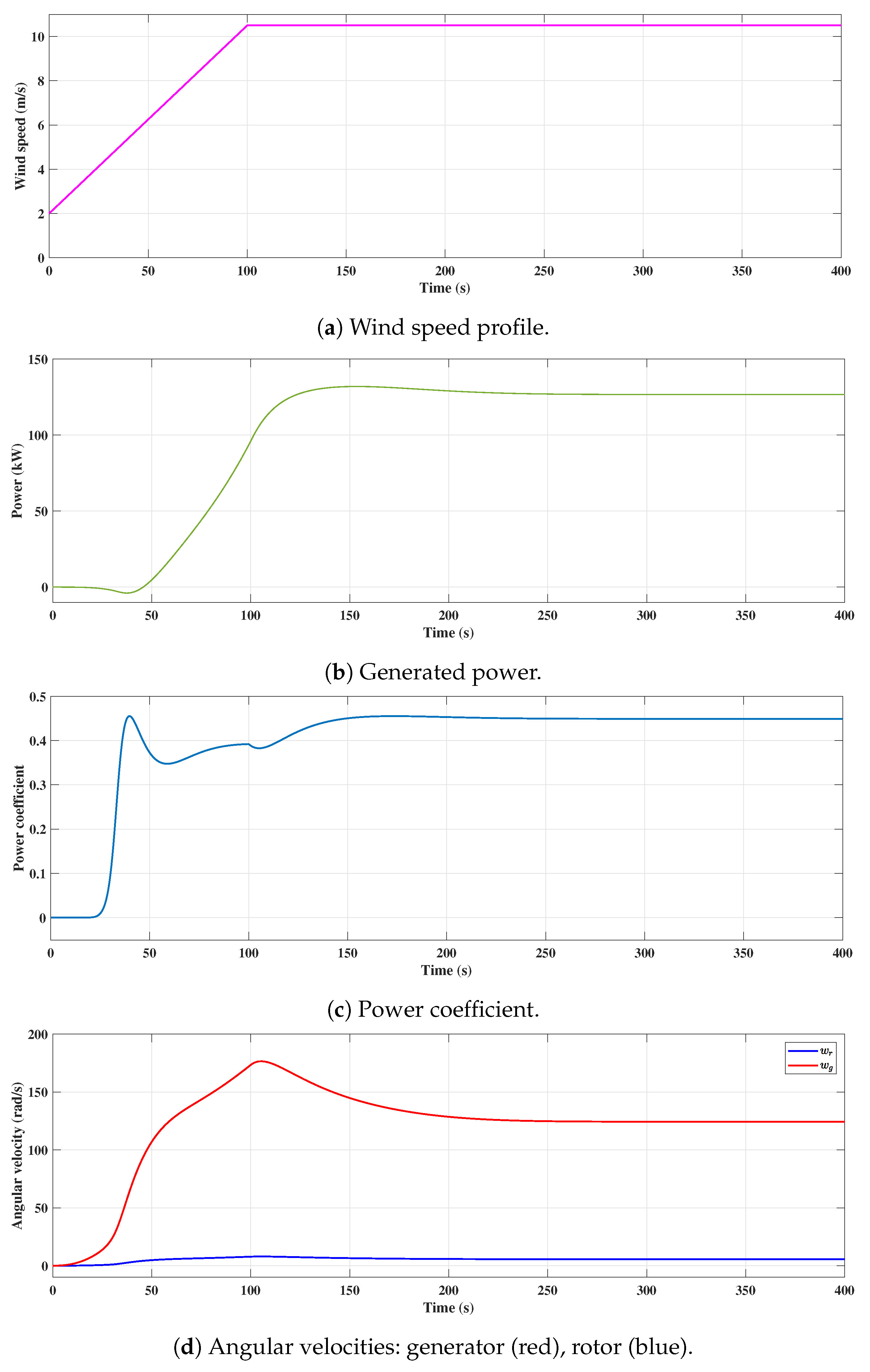
2.3. Wind Turbine Simulation Model and Its Behavior under Normal Condition

We take a small size wind turbine whose system parameters, summarized in Table 1, are taken from [33] and the data-sheet of the T-100 wind turbine of Argolabe S.L. Engineering Company [38]. It is a horizontal axis wind turbine and is designed for distributed generation and (or) electric self-consumption applications, connected to a power grid. According to the data-sheet, the shaft of the rotor and the generator are connected by a gearbox, but by including the gearbox in the inertia of the generator, it can be modeled as a two-inertia model connected by one shaft with torsion, as shown in Figure 1.
Figure 2 is the result of the turbine behavior simulation obtained using the simulation tool Matlab/Simulink. As shown in Figure 2a, wind speed is simulated with the numerical data described under the scenario that the wind speed changes from 0 to 10.5 m/s and reaches 10.5 m/s at 100 s. Figure 2b shows the generated power calculated using (3), it is observed that the generated power in the turbine changes according to the wind speed (V) and power coefficient ( C p ) and that the generated power reaches its maximum after about 200 s. The maximum power is about 133 kW. Figure 2c shows the response of the power coefficient ( C p ), which reaches 0.4724 after about 200 s. The generator angular velocity ( ω g ) and rotor angular velocity ( ω r ) are plotted in Figure 2d. According to the specifications [38], the rated speed of the rotor is 5.6 rad/s and the gear ratio is 22.2. Using this information, the generator speed ω g is plotted considering the gear ratio, of which the rated value is 124.32 rad/s. A PI controller is used to control the angular velocity of the generator and the gains are chosen as K p = 400 and K I = 600. In Figure 2d, as the wind speed changes—as shown in Figure 2a—it is observed that the generator angular velocity reaches 124.32 rad/s after 200 s so that the rotor angular velocity reaches its rated value.
It is noted that the steady state behavior of this wind turbine is obtained under the condition that no cyberattack has been injected. In what follows, we consider the case where the system is under a ZDA that is obtained from this steady state condition (i.e., the information on the operating point) and show that the presence of the attack cannot be detected for a considerably long time interval.

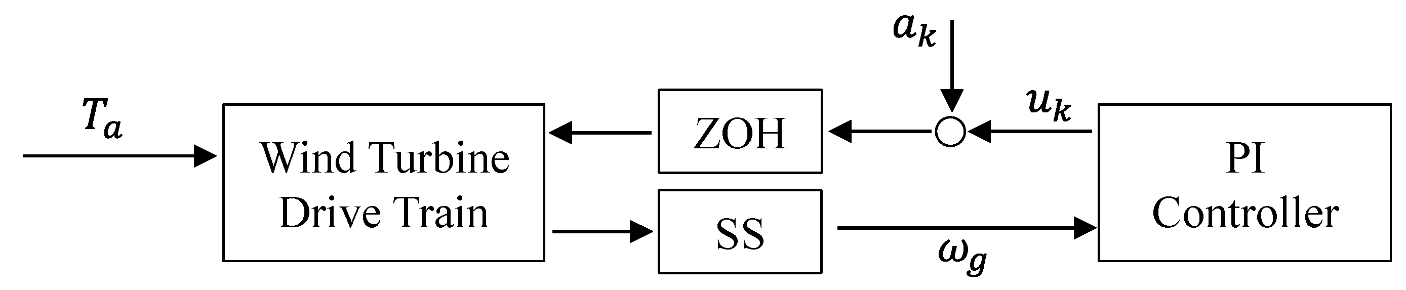
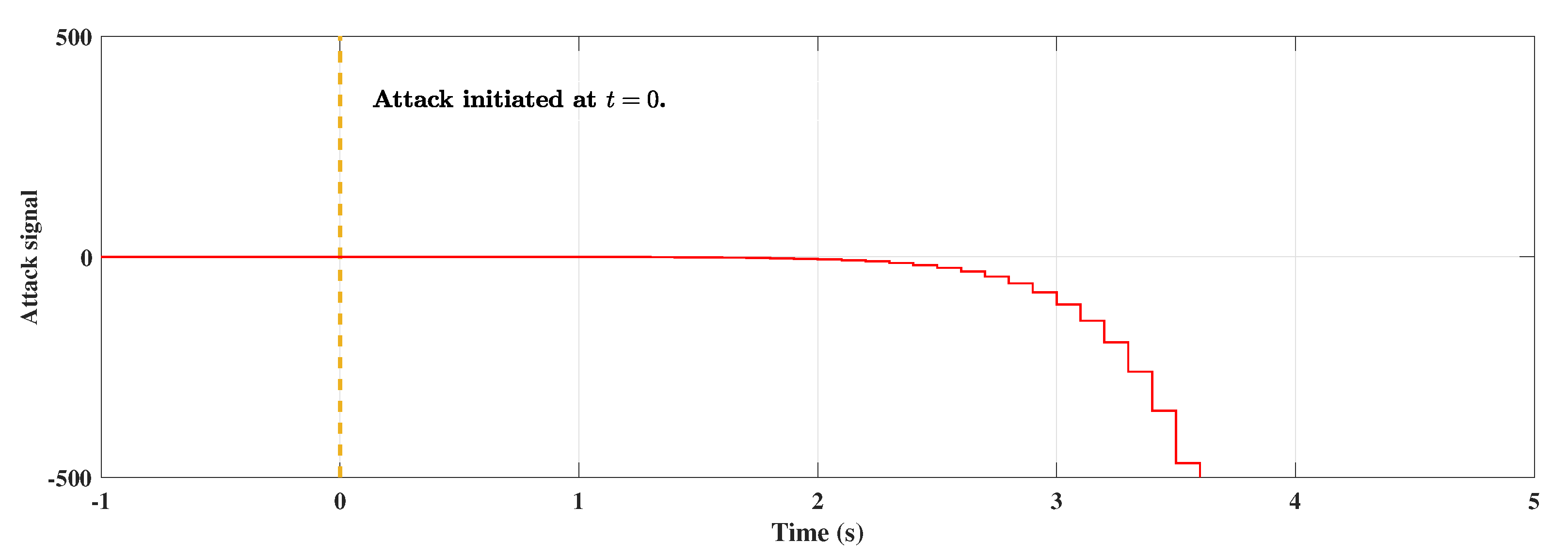
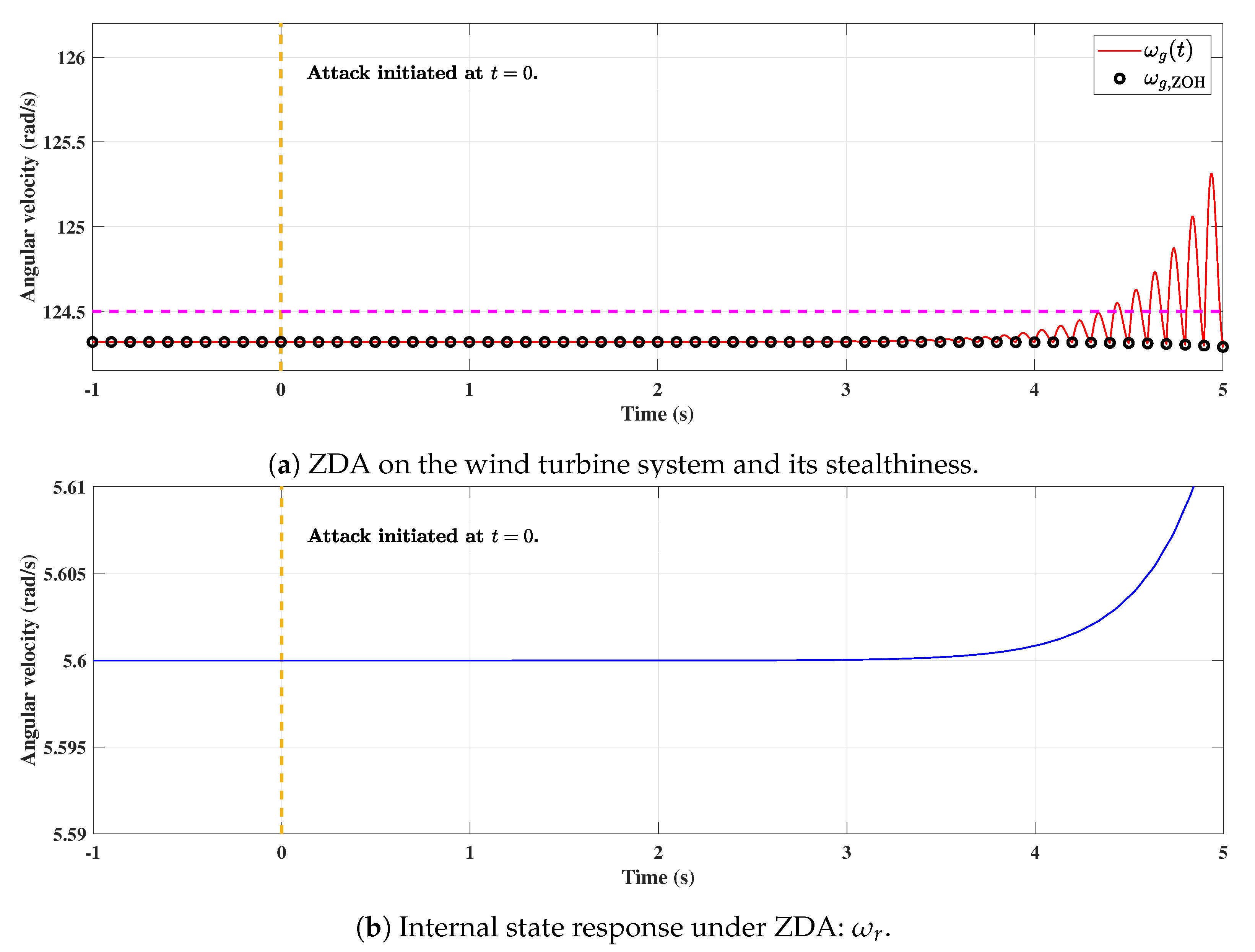
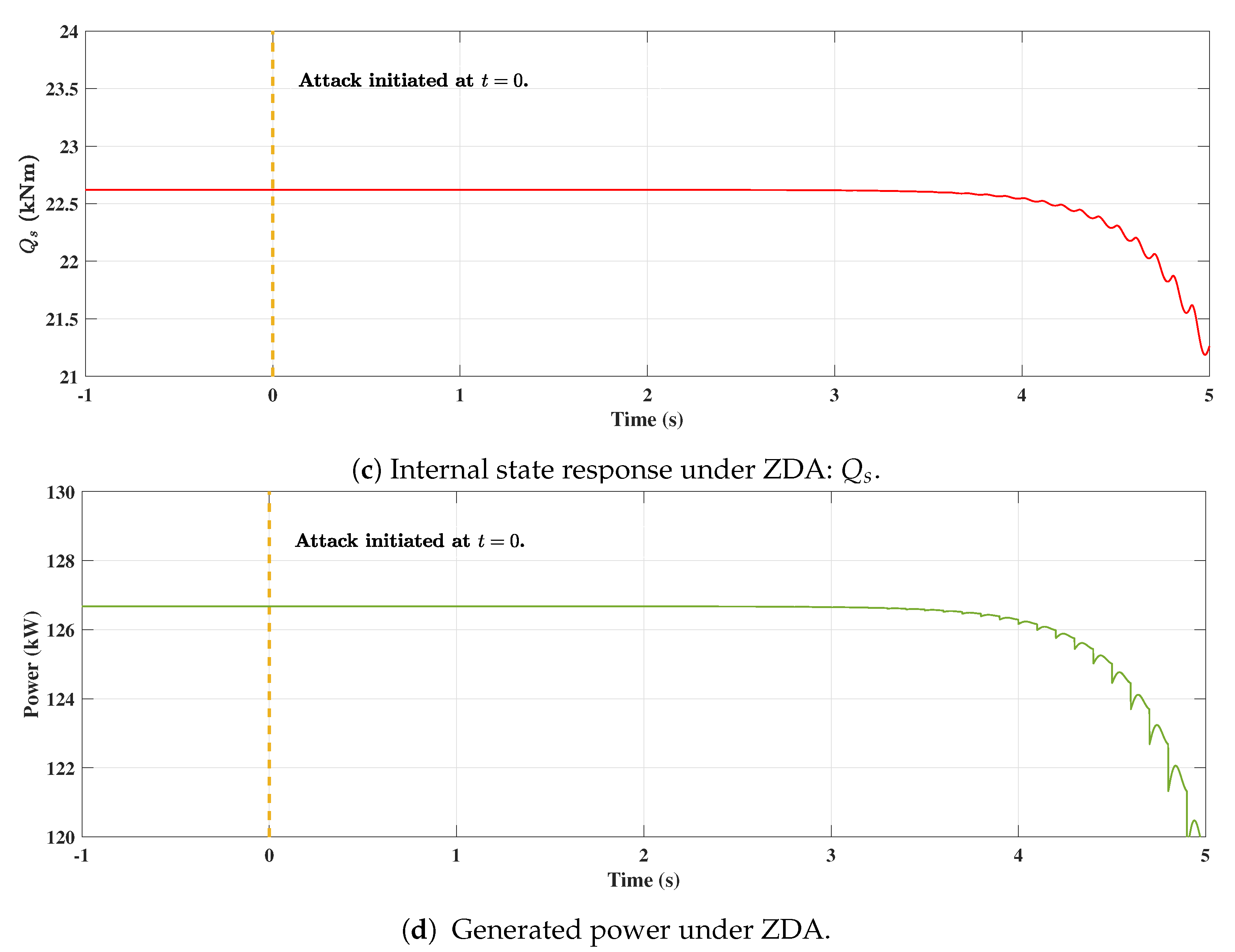
3. Zero-Dynamics Attack on Wind Turbine

Thanks to the development of communication and computing technology, modern wind turbine systems are generally operated by remote control and monitoring systems such as SCADA systems [39,40,41]. Operating wind power generators using the SCADA system enables efficient monitoring and control over wide areas such as wind farms [42,43]. An operator of the SCADA system can comprehensively manage the system based on the signals delivered through the network such as rotor and generator speed, wind speed, and generator torque; see, e.g., [39,40] for details. For the reasons discussed above, the network-based monitoring (or controlling) systems bring an advantage in terms of efficient management of the system. Through a communication network, multiple wind turbines installed in a wide area can be managed in one place, which can result in reduced manpower and immediate state monitoring [44,45].
However, there are also problems with network usage, such as vulnerabilities to cyberattack. If a large area is connected through communication lines, the number of paths through which an attacker with a malicious purpose can inject signals into the system may increase [46,47,48]. In fact, many studies on cyberattacks using these vulnerabilities have been conducted recently [8,49], such as data integrity attack [6], false-data injection attack [50], ZDA [7], etc. Among these cyberattacks, ZDA is one of the sophisticated cyberattacks based on system dynamics [23,24].
Consider a wind turbine system that operates as shown in Figure 3. The turbine receives control input from a remote controller and feeds the system state back to the controller through a network. ZDA becomes possible by occupying the network line between the controller and target system.
Assume that the attacker who has taken control of the network line knows the model information of the system and can add the attack signal a k to the controller output, as shown in Figure 4. Then, using the system model, the attacker can generate a sophisticated attack signal that enables the discrete-time output signal to pretend that the system is operating normally but make the internal state actually unbounded [51,52]. The mathematical explanation for the zero-dynamics attack is as follows:
From (8), the dynamics of the wind turbine under ZDA becomes
x ^ k + 1 = A ^ d x ^ k + B ^ d ( u ^ k + a k ) y ^ k = C d x ^ k ,
where a k is the attack signal of ZDA. The attack signal a k is generated from a dynamic system which is identical to the zero dynamics of the system. We recall that the zero dynamics of the system (9) can be identified by rewriting it in the normal form [53] given by
η k + 1 = S d η k + P d ξ k , η k R 2 ξ k + 1 = ψ d η k + ϕ d ξ k + g d ( u ^ k + a k ) , ξ k R y ^ k = ξ k ,
where the dynamics of ξ k explains how the input u k directly affects the system output ( y ^ k + 1 explicitly depends on u k ) and that of η k describes the internal behavior of the system. The dynamics η k + 1 = S d η k is called the zero dynamics and the eigenvalues of S d correspond to the zeros of the system (9).
The attack signal a k of ZDA is generated from a dynamic system given by
a k = 1 g d ψ d z k , z k + 1 = S d z k ,
where z k R 2 is the state of attack generator. It is noted that the attack is constructed using the system parameters such as S d , ψ d , and g d .
Now, we investigate the behavior of the closed-loop system under ZDA. Firstly, the controller C PI ( z ) represented in the state space
c k + 1 = c k + e k , e k = y ^ k u ^ k = k I c k + k P e k ,
has been designed so that the closed-loop system under no ZDA is stable, as demonstrated in Section 2.3, namely, the matrix A ^ CL shown below is Schur.
A ^ CL = S d P d 0 ψ d ϕ d g d k P g d k I 0 1 1 .
When the attack a k generated by (11) is injected into system (10) (it is equivalent to system (9)), we can derive
η k + 1 ξ k + 1 c k + 1 z k + 1 = S d P d 0 0 ψ d ϕ d g d k P g d k I ψ d 0 1 1 0 0 0 0 S d η k ξ k c k z k ,
from which one has
η k + 1 z k + 1 ξ k + 1 c k + 1 = A ^ CL η k z k ξ k c k .
Since A ^ CL given in (12) is Schur, there exist κ > 0 and λ with | λ | < 1 such that
η k z k ξ k c k κ λ k η 0 z 0 ξ 0 c 0 .
This relation implies that under a ZDA, the internal state η k converges to the state of ZDA, while other states ξ k and c k converge to zero.
It is remarkable that the relation (13) holds regardless of the stability of the zero dynamics. Hence, if S d is unstable, then the internal state η k diverges whenever z 0 depends on an unstable eigenvector of S d , while this behavior cannot be observed by monitoring the signal ( ξ k , c k ) .
Unfortunately, the wind turbine system (8) has an unstable zero when the sample time T s belongs to some region. Figure 5a shows the locus of the zeros with respect to the sampling time from T s = 0.001 s to T s = 0.1 s. When T s = 0.001 s, two zeros are located near 1, as depicted by the crosses. When T s increases and then becomes 0.08 s, z 2 is located outside the unit circle. The blue and red circles on the real axis in Figure 5a indicate the location of two zeros when T s = 0.1 s. As shown in Figure 5b, if T s [ 0.08 , 0.13 ] s, at least one zero is located outside the unit circle.
Suppose that T s belongs to the region where the wind turbine has an unstable zero. When the attack (11) is injected, the rotor angular velocity ω r and the (spring) torsional torque Q s will diverge while the generator angular velocity ω g and the controller state c k converge to zero. This can be interpreted so that the attack intentionally moves two components ( ω r and Q s ) of the operating point but leaves ω g at the normal operating point and deceives the controller as if all components remain unchanged.
Under the situation described in Figure 4, the effect of ZDA on the wind turbine system is presented. Since the system is of nonminimum phase when T s = 0.1 s, the attack signal diverges for an appropriately chosen initial condition as shown in Figure 6, and it is expected that the internal states also diverge. Suppose that the hacker injected a k through the communication network at t = 0 . Let ω ^ g , Th be a threshold that the steady state value of ω ^ g should not exceed (the dotted line in Figure 7a and ω ^ g , Th = 0.18 rad/s), in other words, if | ω ^ g | > ω ^ g , Th , the monitoring system determines that a fault has occurred or an attack has been injected. As can be seen in Figure 7a, the continuous-time output y ( t ) = ω g ( t ) —the generator speed—becomes unbounded, while the discrete-time signal y k = ω g , ZOH that is transmitted to the controller and the SCADA system remain almost unchanged, indicating that the wind turbine still operates normally.
Meanwhile, the attack also affects the generated power and internal state. Figure 7b,c show the responses of the internal states ω r and Q s , respectively, and it is observed that ω r and Q s become unbounded. In addition, the generated power under ZDA decreases, as shown in Figure 7d.

4. Two Countermeasures against Zero-Dynamics Attack

ZDA becomes effective when the discrete-time system has an unstable zero and, as discussed in Section 3, it can happen even if the continuous-time system has stable zero dynamics. Among several countermeasures to ZDA, we introduce two strategies that share the same idea, shifting zeros. These approaches are based on the fact that the zeros of the discrete-time system can be arbitrarily assigned if the ZOH is replaced by a generalized hold (GH) or if a generalized sampler (GS) is used instead of SS [20]. Applications of these ideas to security problems are reported in [23,24], and in this section, we apply these approaches to wind turbine systems.

4.1. Generalized-Hold-Based Strategy

GH has been introduced in [20] and involves a function h g ( t ) , the so-called hold function that is defined as a piecewise continuous function h g so that the actual input applied to the system is given by
u ^ ( t ) = k = h g ( t k T s ) u ^ k .
If a GH having a hold function h g ( t ) is used instead of ZOH, the sampled-data model of wind turbine system (6) under constant wind speed V ¯ (so that V ^ = 0 ) and ZDA becomes
x ^ k + 1 = A ^ d x ^ k + B ^ g ( u ^ k + a k ) y ^ k = C d x ^ k ,
where A ^ d = e A ^ s T s , B ^ g = 0 T s e A ^ s ( T s τ ) B ^ s h g ( τ ) d τ , and C d = C s . The discrete-time transfer function from the generator torque u ^ k ( = T ^ g ) (equivalently from the attack a k ) to generator angular velocity y ^ k ( = ω ^ g ) , denoted by G d ( z ) , is then given by
G d ( z ) = C d ( z I A ^ d ) 1 B ^ g .
It is emphasized that since ( A ^ s , B ^ s ) is controllable, one can always find a hold function h g so that the zeros of G d ( z ) can be placed anywhere in the complex plane [20,23].
Let z d , 1 and z d , 2 be the desired zeros located inside the unit circle and k d be a gain. The problem is to find B ^ g such that the transfer function G d ( z ) has desired zeros and gain, i.e., the following identity holds
G d ( z ) = C d ( z I A ^ d ) 1 B ^ g = k d ( z z d , 1 ) ( z z d , 2 ) det ( z I A ^ d ) = : G d * ( z ) .
Let det ( z I A ^ d ) = z 3 + d 2 z 2 + d 1 z + d 0 . Then, G d * ( z ) can be realized in the control canonical form [54] given by
x ¯ k + 1 = A con x ¯ k + B con u ¯ k y ¯ k = C con x ¯ k ,
where
A con = 0 1 0 0 0 1 d 0 d 1 d 2 , B con = 0 0 1 , C con = k d z d , 1 z d , 2 k d ( z d , 1 + z d , 2 ) k d .
Equating the Markov parameters of the two transfer functions, one has
C d A ^ d k B ^ g = C con A con k B con , k = 0 , 1 , ,
from which B ^ g is determined by
B ^ g = C d C d A ^ d C d A ^ d 2 1 C con C con A con C con A con 2 B con ,
where the invertibility is assured by the observability of ( A ^ d , C d ) .
As discussed in [20,23], one candidate of GH is to use a piecewise constant function given by
h g ( t ) = h i , ( i 1 ) T s N t < i T s N , i = 1 , , N ,
where h i are constant gains and N is the number of subintervals. It can be shown that the gains h i and the vector B ^ g are related as
B ^ g = l = 1 N h l ( l 1 ) T s N l T s N e A ^ s ( T s τ ) B ^ s d τ
and this can be rewritten as
B ^ g = A d , N N 1 B d , N A d , N B d , N B d , N h = : C d , N h ,
where h = [ h 1 , , h N ] and
A d , N = e A ^ s T s N , B d , N = 0 T s N e A ^ s ( T s N τ ) B ^ s d τ .
The hold gains are then computed as
h = C d , N B ^ g .
For more details on the derivation, see [23].

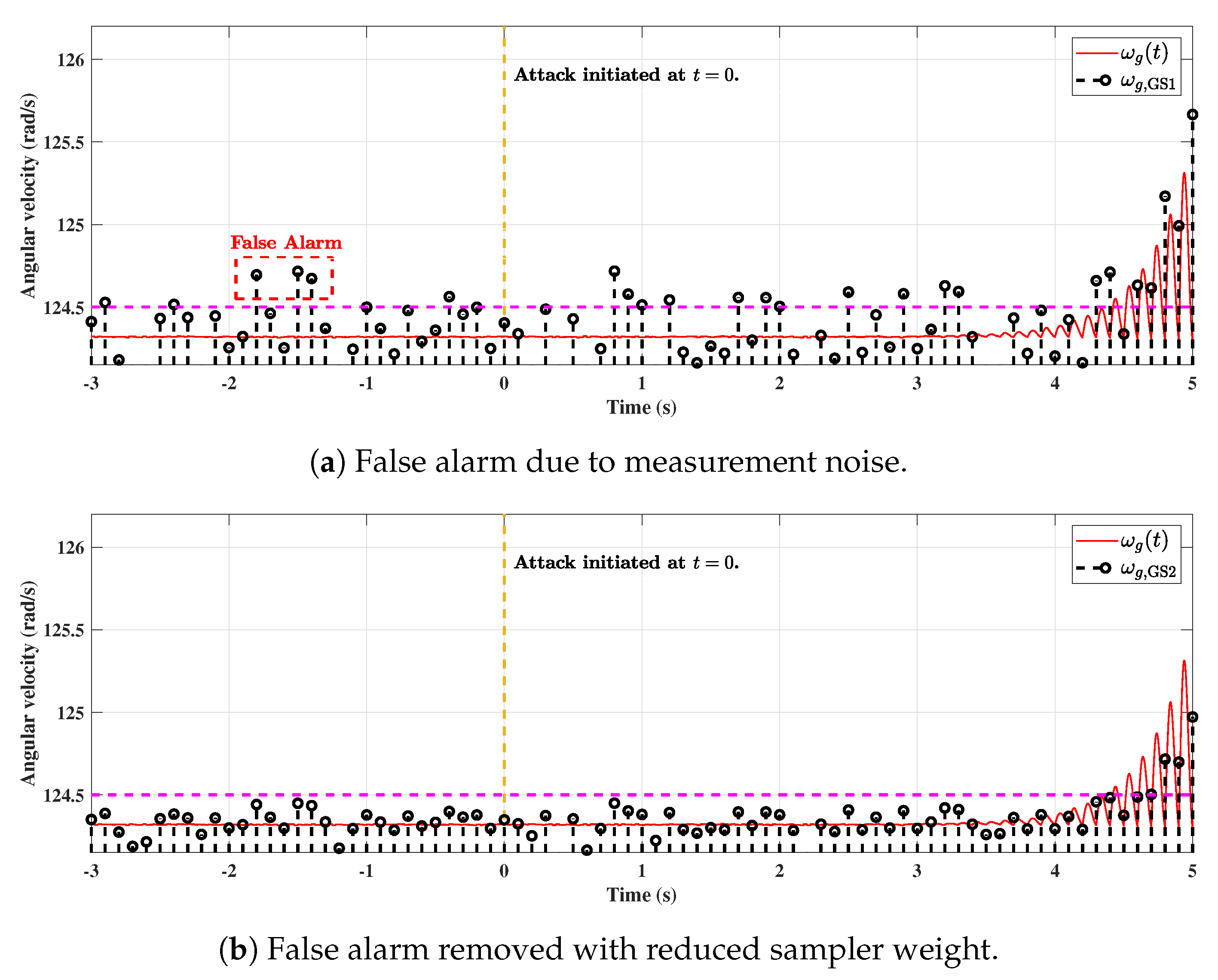
4.2. Generalized-Sampler-Based Approach

By GS, we mean a device that generates a discrete-time signal y ˘ k from a continuous-time signal y ( t ) in a way that N measurements (i.e., generator angular velocity) y ( 1 N T s + ( k 1 ) T s ) , y ( 2 N T s + ( k 1 ) T s ) , , y ( k T s ) are taken from the sampling interval ( ( k 1 ) T s , k T s ] and a weighted average of them is computed as
y ˘ k = i = 1 N w i y i N T s + ( k 1 ) T s ,
where w 1 , , w N are weights for GS.
Similar to the case of GH, we can rewrite the system (6) under constant wind speed and ZDA as
x ^ k = A ^ d x ^ k 1 + B ^ d ( u ^ k 1 + a k 1 ) y ˘ k = C ˘ d x ^ k 1 + D ˘ d ( u ^ k 1 + a k 1 ) ,
where
A ^ d = e A ^ s T s , B ^ d = 0 T s e A ^ s ( T s τ ) B ^ s d τ C ˘ d = i = 1 N w i C d e A ^ s i N T s , D ˘ d = i = 1 N w i C d 0 i N T s e A ^ s ( i N T s τ ) B ^ s d τ .
From (21), we can compute the transfer function from u ^ k to y ^ k as
G d ( z ) = z 1 ( C ˘ d ( z I A ^ d ) 1 B ^ d + D ˘ d ) .
Note that C ˘ d and D ˘ d contain the sampler weights w 1 , ⋯, w N of GS, which are design parameters. If the weights are chosen appropriately, it is expected that the numerator of the transfer function (22) can be chosen as desired. In fact, this is true under mild assumptions [24].
Let z d , 1 , z d , 2 , and z d , 3 be the desired zeros whose magnitudes are less than 1. We want to find the weights of GS such that the transfer function G d ( z ) becomes identical to
G d * ( z ) = k d z 1 ( z z d , 1 ) ( z z d , 2 ) ( z z d , 3 ) det ( z I A ^ d ) ,
where k d is a high-frequency gain. To proceed, let c 0 , c 1 , c 2 be such that ( z z d , 1 ) ( z z d , 2 ) ( z z d , 3 ) = z 3 + c 2 z 2 + c 1 z + c 0 . We first find C ˘ d and D ˘ d , then determine the weights w i . As in the case of GH, we realize (23) in the control canonical form given by
x ¯ k = A con x ¯ k 1 + B con u ¯ k 1 y ¯ k = C con x ¯ k 1 + D con u ¯ k 1 ,
where A con and B con are identical to those of (16), and
C con = k d ( c 0 d 0 ) k d ( c 1 d 1 ) k d ( c 2 d 2 ) , D con = k d .
From the fact that two transfer functions G d ( z ) and G d * ( z ) are identical if and only if
D ˘ d = D con C ˘ d A ^ d k B ^ d = C con A con k B con , k = 0 , 1 , ,
we have, from the controllability of ( A ^ d , B ^ d ) ,
C ˘ d = C con B con A con B con A con 2 B con B ^ d A ^ d B ^ d A ^ d 2 B ^ d 1 D ˘ d = k d .
With C ˘ d and D ˘ d obtained above, it follows from the relation between the weights and ( C ˘ d , D ˘ d ) that
C ˘ d D ˘ d = w C d e A ^ s 1 N T s C d 0 1 N T s e A ^ s ( 1 N T s τ ) B ^ s d τ C d e A ^ s 2 N T s C d 0 2 N T s e A ^ s ( 2 N T s τ ) B ^ s d τ C d e A ^ s T s C d 0 T s e A ^ s ( T s τ ) B ^ s d τ = : w M ,
and the weights are computed as
w = C ˘ d D ˘ d M ,
where M is the pseudo-inverse of M. For more details, see [24].

5. Evaluation of Countermeasures against ZDA

In this section, we apply the theory given in Section 4 and demonstrate that the two countermeasures that can shift the zeros into the stable region effectively reveal the presence of ZDA. Although both approaches work well in ideal situations, they also face challenges arising from practical issues such as nonlinearities and measurement noise. These issues are also discussed through intensive numerical simulations.
Following the procedure described in Section 4, a GH is designed so that the discrete-time system has zeros at z d , 1 = 0.1 and z d , 1 = 0.9 . We use a piecewise constant hold function with three subintervals ( N = 3 ) and the hold gain is h = [ 2.155 , 0.577 , 1.422 ] . The sampling time is given by T s = 0.1 s. Figure 8 shows the behavior of the system under the ZDA (11) that has been designed using the system parameters S d , g d , and ψ d assuming that ZOH and SS are used to interface analog and digital signals. The attack is injected when the system is at a steady state (rated power point). It is seen that the generator angular velocity ω g ( t ) starts oscillating with increasing magnitude and this is captured by the sampled output ω g ( k T s ) (denoted as ω g , GH in the figure) when GH is used, while the sampled output under ZOH remains almost unchanged. It is noted that the signal ω g , ZOH also diverges as time goes to infinity but very slowly compared to ω g , GH , which means that it is practically meaningless to use ω g , ZOH as a monitoring signal for the purpose of attack detection. This comes from the nonlinearity of the wind turbine; the diverging attack signal makes the state variables escape the region where the linear approximation is valid.
It is well known that even though a GH can shift the zeros to desired locations, it may induce a violent transient between sampling instants [20]. Typically, this can happen when the pattern associated to the GH has a large transition. For example, consider the GH designed above and suppose that the control input generated by the GH using u k = T ¯ g , shown in Figure 9a, is applied to the wind turbine. Then, as can be seen in Figure 9b, the sampled output ω g , GH seems to converge to a constant, but its continuous-time counterpart oscillates severely, and this can happen even if no attack is injected.
The possibly undesirable intersample behavior can be avoided by using GS instead of SS at the output side and using ZOH at the input side. To demonstrate this, we follow the design described in Section 4 to obtain a GS with N = 4 and w = [ 28.252 , 58.5731 , 70.906 , 41.5846 ] so that the zeros are placed at z d , 1 = 0.1 , z d , 2 = 0.9 , and z d , 3 = 0 . Figure 10 shows that the presence of ZDA can be detected by monitoring the signal ω g , GS , which is the output of the GS. In the simulation, the same ZDA injected in the case of GH is used. It is emphasized that the behavior of the internal states are the same as the case with ZOH and SS shown in Figure 7, and it is free of violent intersample behavior possibly induced by a GH.
In practice, the noise of measurements is always present and if the weights of GS are very large, then the noise will be amplified, leading to a false alarm. To demonstrate this, suppose that the measurement ω g ( t ) is contaminated by noise and consider two designs of GS: GS1 with w = [ 28.252 , 58.5731 , 70.906 , 41.5846 ] and z d , 1 = 0.1 , z d , 2 = 0.9 , z d , 3 = 0 ; GS2 with w = [ 8.924 , 18.983 , 22.903 , 13.844 ] and z d , 1 = 0.1 , z d , 2 = 0.7 , z d , 3 = 0 . Figure 11 shows the effect of the measurement noise under the same setting of Figure 10. The sampled output of GS y ˘ k is denoted by ω g , GS in the figure. In Figure 11a, some of the sampled outputs of GS ω g , GS 1 exceed the threshold although no attack signal is injected, leading to a false alarm. On the contrary, Figure 11b shows that GS2 with relatively smaller weights is less affected by measurement noise.
Since the sampler weights depend on the location of desired zeros, we numerically investigate how they are related. With N and z d , 3 fixed as N = 4 and z d , 3 = 0 , the desired zeros z d , 1 , z d , 2 are selected from ( 1 , 1 ) × ( 1 , 1 ) and the corresponding sampler weights are determined. The result is shown in Figure 12a. In addition, by doing the simulation with the designed GS, we count the number of false alarms, see Figure 12b. It is observed that the number of false alarms is roughly proportional to the norm of sampler weights, and this explains why GS2 is less sensitive to measurement noise.

6. Conclusions

In this paper, we study the security problem on wind turbines that are controlled and monitored through the communication network. It is shown that at the rated power point, the linearized discrete-time model of the wind turbine has an unstable zero for a range of sampling periods, which means that wind turbines that are digitally controlled are vulnerable to zero-dynamics attacks. In order to increase security against ZDA, two countermeasures based on generalized hold and generalized sampler have been proposed with detailed design procedures, and through numerical simulations, it is shown that these approaches make ZDA ineffective. Practical issues such as nonlinearities and measurement noise are discussed in detail.
We are currently working on a robust and optimal design of the proposed strategies, which are challenging research topics. Validation of the proposed approaches using more realistic models or software and simultaneous design of two components are also interesting future research topics.

Author Contributions

Idea development and analysis, D.K. and K.R.; writing—original draft, D.K. and K.R.; supervision, J.B. All authors have read and agreed to the published version of the manuscript.

Funding

This work was supported by the Korea Institute of Energy Technology Evaluation and Planning (KETEP) grant funded by the Korea government(MOTIE) (20204030200010, Graduate Track for Core Technologies of Wind Power System Engineering) and the Research Grant of Kwangwoon University in 2019.

Institutional Review Board Statement

Not applicable.

Informed Consent Statement

Not applicable.

Data Availability Statement

Not applicable.

Conflicts of Interest

The authors declare no conflict of interest.

References

  1. International Renewable Energy Association. Future of Wind: Deployment, Investment, Technology, Grid Integration and Socio-Economic Aspects (A Global Energy Transformation Paper); International Renewable Energy Agency: Abu Dhabi, United Arab Emirates, 2017. [Google Scholar]
  2. Lee, R.M.; Assante, M.J.; Conway, T. German steel mill cyber attack. Ind. Control. Syst. 2014, 30, 62. [Google Scholar]
  3. Kesler, B. The vulnerability of nuclear facilities to cyber attack. Strateg. Insights 2011, 10, 15–25. [Google Scholar]
  4. Alert, I.C. Cyber-Attack against Ukrainian Critical Infrastructure; Tech. Rep. ICS Alert (IR-ALERT-H-16-056-01); Cybersecurity Infrastruct. Secur. Agency: Washington, DC, USA, 2016. [Google Scholar]
  5. Cárdenas, A.A.; Amin, S.; Lin, Z.S.; Huang, Y.L.; Huang, C.Y.; Sastry, S. Attacks Against Process Control Systems: Risk Assessment, Detection, and Response. In Proceedings of the 6th ACM Symposium on Information, Computer and Communications Security (ASIACCS ’11), Hong Kong, China, 22–24 March 2011; pp. 355–366. [Google Scholar]
  6. Sridhar, S.; Manimaran, G. Data integrity attacks and their impacts on SCADA control system. In Proceedings of the IEEE PES General Meeting, Providence, RI, USA, 25–29 July 2010; pp. 1–6. [Google Scholar] [CrossRef]
  7. Teixeira, A.; Shames, I.; Sandberg, H.; Johansson, K.H. Revealing stealthy attacks in control systems. In Proceedings of the 2012 50th Annual Allerton Conference on Communication, Control, and Computing (Allerton), Monticello, IL, USA, 1–5 October 2012; pp. 1806–1813. [Google Scholar]
  8. Teixeira, A.; Shames, I.; Sandberg, H.; Johansson, K.H. A secure control framework for resource-limited adversaries. Automatica 2015, 51, 135–148. [Google Scholar] [CrossRef] [Green Version]
  9. Ding, D.; Han, Q.L.; Ge, X.; Wang, J. Secure state estimation and control of cyber-physical systems: A survey. IEEE Trans. Syst. Man Cybern. Syst. 2020, 51, 176–190. [Google Scholar] [CrossRef]
  10. Mahmoud, M.S.; Hamdan, M.M.; Baroudi, U.A. Modeling and control of cyber-physical systems subject to cyber attacks: A survey of recent advances and challenges. Neurocomputing 2019, 338, 101–115. [Google Scholar] [CrossRef]
  11. Giraldo, J.; Urbina, D.; Cardenas, A.; Valente, J.; Faisal, M.; Ruths, J.; Tippenhauer, N.O.; Sandberg, H.; Candell, R. A survey of physics-based attack detection in cyber-physical systems. ACM Comput. Surv. (CSUR) 2018, 51, 1–36. [Google Scholar] [CrossRef]
  12. Wood, A.D.; Stankovic, J.A. Denial of service in sensor networks. Computer 2002, 35, 54–62. [Google Scholar] [CrossRef] [Green Version]
  13. Mallikarjunan, K.N.; Muthupriya, K.; Shalinie, S.M. A survey of distributed denial of service attack. In Proceedings of the 2016 10th International Conference on Intelligent Systems and Control (ISCO), Coimbatore, India, 7–8 January 2016; pp. 1–6. [Google Scholar]
  14. Agarwal, M.; Purwar, S.; Biswas, S.; Nandi, S. Intrusion detection system for PS-Poll DoS attack in 802.11 networks using real time discrete event system. IEEE/CAA J. Autom. Sin. 2016, 4, 792–808. [Google Scholar] [CrossRef]
  15. Li, X.; Wang, Q.; Dai, H.N.; Wang, H. A novel friendly jamming scheme in industrial crowdsensing networks against eavesdropping attack. Sensors 2018, 18, 1938. [Google Scholar] [CrossRef] [Green Version]
  16. Malladi, S.; Alves-Foss, J.; Heckendorn, R.B. On Preventing Replay Attacks on Security Protocols; Technical Report; Idaho University Moscow Department of Computer Science: Moscow, Idaho, 2002. [Google Scholar]
  17. Schellenberger, C.; Zhang, P. Detection of covert attacks on cyber-physical systems by extending the system dynamics with an auxiliary system. In Proceedings of the 2017 IEEE 56th Annual Conference on Decision and Control (CDC), Melbourne, Australia, 12–15 December 2017; pp. 1374–1379. [Google Scholar] [CrossRef]
  18. Park, G.; Shim, H.; Lee, C.; Eun, Y.; Johansson, K.H. When adversary encounters uncertain cyber-physical systems: Robust zero-dynamics attack with disclosure resources. In Proceedings of the 2016 IEEE 55th Conference on Decision and Control (CDC), Las Vegas, NV, USA, 12–14 December 2016; pp. 5085–5090. [Google Scholar]
  19. Jeon, H.; Eun, Y. A Stealthy Sensor Attack for Uncertain Cyber-Physical Systems. IEEE Internet Things J. 2019, 6, 6345–6352. [Google Scholar] [CrossRef]
  20. Yuz, J.I.; Goodwin, G.C. Sampled-Data Models for Linear and Nonlinear Systems; Springer: London, UK, 2014. [Google Scholar]
  21. Hoehn, A.; Zhang, P. Detection of covert attacks and zero dynamics attacks in cyber-physical systems. In Proceedings of the 2016 American Control Conference (ACC), Boston, MA, USA, 6–8 July 2016; pp. 302–307. [Google Scholar]
  22. Naghnaeian, M.; Hirzallah, N.; Voulgaris, P.G. Dual rate control for security in cyber-physical systems. In Proceedings of the 2015 54th IEEE Conference on Decision and Control (CDC), Osaka, Japan, 15–18 December 2015; pp. 1415–1420. [Google Scholar] [CrossRef] [Green Version]
  23. Kim, J.; Back, J.; Park, G.; Lee, C.; Shim, H.; Voulgaris, P.G. Neutralizing zero dynamics attack on sampled-data systems via generalized holds. Automatica 2020, 113, 108778. [Google Scholar] [CrossRef]
  24. Kim, D.; Ryu, K.; Back, J. Security Enhancement of Sampled-Data Systems: Zero Assignment via Generalized Sampler. In Proceedings of the 21st IFAC World Congress 2020, Berlin, Germany, 12–17 July 2020. [Google Scholar]
  25. Naghnaeian, M.; Hirzallah, N.; Voulgaris, P.G. Security via multirate control in cyber–physical systems. Syst. Control. Lett. 2019, 124, 12–18. [Google Scholar] [CrossRef]
  26. Mao, Y.; Jafarnejadsani, H.; Zhao, P.; Akyol, E.; Hovakimyan, N. Novel stealthy attack and defense strategies for networked control systems. IEEE Trans. Autom. Control. 2020, 65, 3847–3862. [Google Scholar] [CrossRef]
  27. Gallo, A.J.; Turan, M.S.; Boem, F.; Parisini, T.; Ferrari-Trecate, G. A distributed cyber-attack detection scheme with application to DC microgrids. IEEE Trans. Autom. Control. 2020, 65, 3800–3815. [Google Scholar] [CrossRef]
  28. Singh, M.; Santoso, S. Dynamic Models for Wind Turbines and Wind Power Plants; Technical Report; National Renewable Energy Laboratory (NREL): Golden, CO, USA, 2011. [Google Scholar]
  29. Lubosny, Z.; Lubosny, Z. Wind Turbine Operation in Electric Power Systems: Advanced Modeling; Springer: Berlin/Heidelberg, Germany, 2003. [Google Scholar]
  30. Bianchi, F.D.; De Battista, H.; Mantz, R.J. Wind Turbine Control Systems: Principles, Modelling and Gain Scheduling Design; Springer Science & Business Media: Berlin/Heidelberg, Germany, 2006. [Google Scholar]
  31. Georg, S.; Schulte, H.; Aschemann, H. Control-oriented modelling of wind turbines using a Takagi-Sugeno model structure. In Proceedings of the 2012 IEEE International Conference on Fuzzy Systems, Brisbane, Australia, 10–15 June 2012; pp. 1–8. [Google Scholar]
  32. Simani, S. Overview of modelling and advanced control strategies for wind turbine systems. Energies 2015, 8, 13395–13418. [Google Scholar] [CrossRef] [Green Version]
  33. Ansoategui, I.; Zulueta, E.; Fernandez-Gamiz, U.; Lopez-Guede, J.M. Mechatronic Modeling and Frequency Analysis of the Drive Train of a Horizontal Wind Turbine. Energies 2019, 12, 613. [Google Scholar] [CrossRef] [Green Version]
  34. Novak, P. On the Modelling and Partial-Load Control of Variable-Speed Wind Turbines; Technical Report; Chalmers University of Technology: Göteborg, Sweden, 19 August 1995. [Google Scholar]
  35. Kim, K.H.; Van, T.L.; Lee, D.C.; Song, S.H.; Kim, E.H. Maximum output power tracking control in variable-speed wind turbine systems considering rotor inertial power. IEEE Trans. Ind. Electron. 2012, 60, 3207–3217. [Google Scholar]
  36. Manyonge, A.W.; Ochieng, R.; Onyango, F.; Shichikha, J. Mathematical modelling of wind turbine in a wind energy conversion system: Power coefficient analysis. Appl. Math. Sci. 2012, 6, 4527–4536. [Google Scholar]
  37. Dai, J.; Hu, Y.; Liu, D.; Wei, J. Modelling and analysis of direct-driven permanent magnet synchronous generator wind turbine based on wind-rotor neural network model. Proc. Inst. Mech. Eng. Part A J. Power Energy 2012, 226, 62–72. [Google Scholar] [CrossRef]
  38. Available online: https://www.argolabe.es/100kw-windturbine.html (accessed on 28 January 2021).
  39. Maldonado-Correa, J.; Martín-Martínez, S.; Artigao, E.; Gómez-Lázaro, E. Using SCADA Data for Wind Turbine Condition Monitoring: A Systematic Literature Review. Energies 2020, 13, 3132. [Google Scholar] [CrossRef]
  40. Pandit, R.; Infield, D. Gaussian process operational curves for wind turbine condition monitoring. Energies 2018, 11, 1631. [Google Scholar] [CrossRef] [Green Version]
  41. Yang, W.; Court, R.; Jiang, J. Wind turbine condition monitoring by the approach of SCADA data analysis. Renew. Energy 2013, 53, 365–376. [Google Scholar] [CrossRef]
  42. Sun, P.; Li, J.; Wang, C.; Lei, X. A generalized model for wind turbine anomaly identification based on SCADA data. Appl. Energy 2016, 168, 550–567. [Google Scholar] [CrossRef] [Green Version]
  43. Zaher, A.; McArthur, S.; Infield, D.; Patel, Y. Online wind turbine fault detection through automated SCADA data analysis. Wind. Energy Int. J. Prog. Appl. Wind. Power Convers. Technol. 2009, 12, 574–593. [Google Scholar] [CrossRef]
  44. Qiu, Y.; Feng, Y.; Tavner, P.; Richardson, P.; Erdos, G.; Chen, B. Wind turbine SCADA alarm analysis for improving reliability. Wind Energy 2012, 15, 951–966. [Google Scholar]
  45. Tautz-Weinert, J.; Watson, S.J. Using SCADA data for wind turbine condition monitoring—A review. IET Renew. Power Gener. 2016, 11, 382–394. [Google Scholar] [CrossRef] [Green Version]
  46. Smith, R.S. Covert misappropriation of networked control systems: Presenting a feedback structure. IEEE Control. Syst. Mag. 2015, 35, 82–92. [Google Scholar]
  47. Mo, Y.; Weerakkody, S.; Sinopoli, B. Physical authentication of control systems: Designing watermarked control inputs to detect counterfeit sensor outputs. IEEE Control. Syst. Mag. 2015, 35, 93–109. [Google Scholar]
  48. Canaan, B.; Colicchio, B.; Ould Abdeslam, D. Microgrid Cyber-Security: Review and Challenges toward Resilience. Appl. Sci. 2020, 10, 5649. [Google Scholar] [CrossRef]
  49. Pasqualetti, F.; Dörfler, F.; Bullo, F. Attack detection and identification in cyber-physical systems. IEEE Trans. Autom. Control. 2013, 58, 2715–2729. [Google Scholar] [CrossRef] [Green Version]
  50. Teixeira, A.; Dán, G.; Sandberg, H.; Johansson, K.H. A cyber security study of a SCADA energy management system: Stealthy deception attacks on the state estimator. IFAC Proc. Vol. 2011, 44, 11271–11277. [Google Scholar] [CrossRef] [Green Version]
  51. Park, G.; Lee, C.; Shim, H.; Eun, Y.; Johansson, K.H. Stealthy adversaries against uncertain cyber-physical systems: Threat of robust zero-dynamics attack. IEEE Trans. Autom. Control. 2019, 64, 4907–4919. [Google Scholar] [CrossRef]
  52. Teixeira, A.; Pérez, D.; Sandberg, H.; Johansson, K.H. Attack models and scenarios for networked control systems. In Proceedings of the 1st International Conference on High Confidence Networked Systems, Beijing, China, 17–18 April 2012; pp. 55–64. [Google Scholar]
  53. Khalil, H.K. Nonlinear Systems, 3rd ed.; Prentice-Hall: Upper Saddle River, NJ, USA, 2002. [Google Scholar]
  54. Chen, C.T. Linear System Theory and Design, 4th ed.; Oxford University Press: New York, NY, USA, 2013. [Google Scholar]
Figure 1. Two-inertia model of the drivetrain.
Applsci 11 01257 g001
Figure 2. Response of the wind turbine under constant wind speed.
Applsci 11 01257 g002
Figure 3. Schematic of remotely monitored and controlled wind turbine systems subject to zero-dynamics attacks. ZDA—zero-dynamics attack; SCADA—supervisory control and data acquisition.
Applsci 11 01257 g003
Figure 4. Wind turbine control system under the zero–dynamics attack at the actuator side. ZOH—zero-order hold; SS—simple sampler; PI—Proportional–Integral.
Applsci 11 01257 g004
Figure 5. (a) Locus of discrete-time zeros and (b) the magnitude of them with respect to the sampling time Ts.
Applsci 11 01257 g005
Figure 6. Zero-dynamics attack a k signal when T s = 0.1 s.
Applsci 11 01257 g006
Figure 7. Responses of the wind turbine under ZDA: with ZOH and SS.
Applsci 11 01257 g007aApplsci 11 01257 g007b
Figure 8. Response of the wind turbine under ZDA, generalized hold (GH) with desired zeros 0.1 and 0.9. (a) Response of system output (generator angular velocity), continuous-time signal ω g , GH (t) and its sampled signal ω g , GH . For comparison, ω g , ZOH (identical to Figure 7a) is also drawn. (b) Response of internal variable, ω r . (c) Response of internal variable, Qs.
Applsci 11 01257 g008
Figure 9. (a) Control input generated by a GH; (b) generator angular velocity ω g (t) and its sampled signal ω g , GH .
Applsci 11 01257 g009
Figure 10. ZDA detection using a generalized sampler (GS).
Applsci 11 01257 g010
Figure 11. GS simulation with measurement noise.
Applsci 11 01257 g011
Figure 12. Effect of the location of desired zeros on the size of sampler weight and the number of false alarms.
Applsci 11 01257 g012
Table 1. Model parameters of a small-sized wind turbine.
J r J g K s h R λ o p t C p , m a x
30,375 kg · m 2 151 kg · m 2 0.31 × 10 6 N·m/rad11.25 m647.24%
Publisher’s Note: MDPI stays neutral with regard to jurisdictional claims in published maps and institutional affiliations.

