
A Novel Method for Field Measurement of Ankle Joint Stiffness in Hopping

 , ,
, , 
Abstract
:1. Introduction
2. Materials and Methods
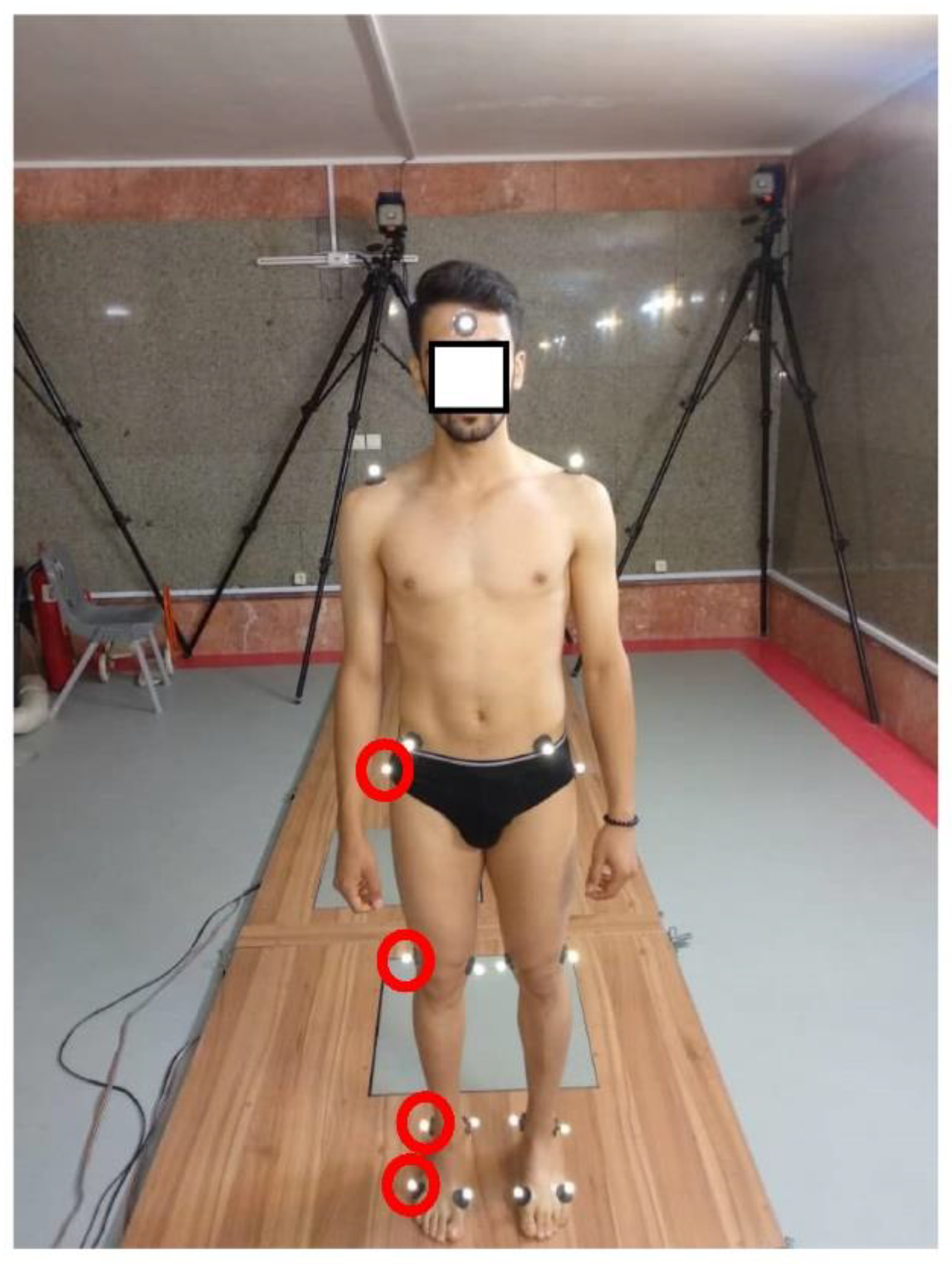
2.1. Participants, Procedures, and Equipment
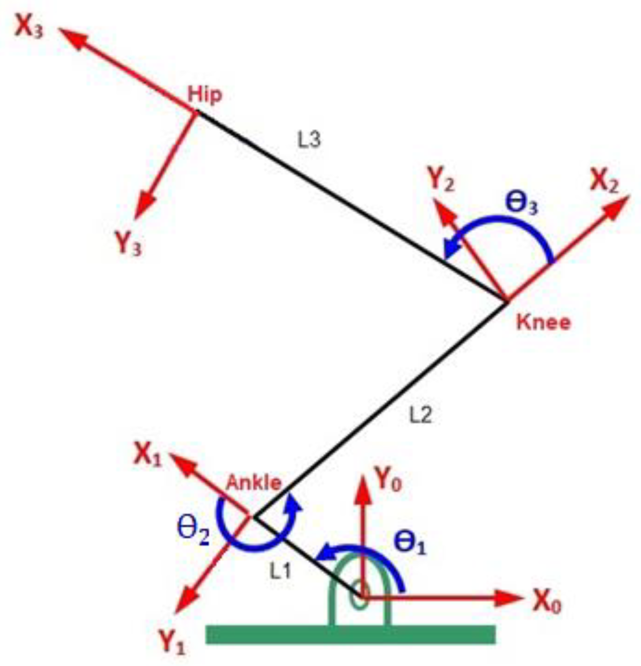
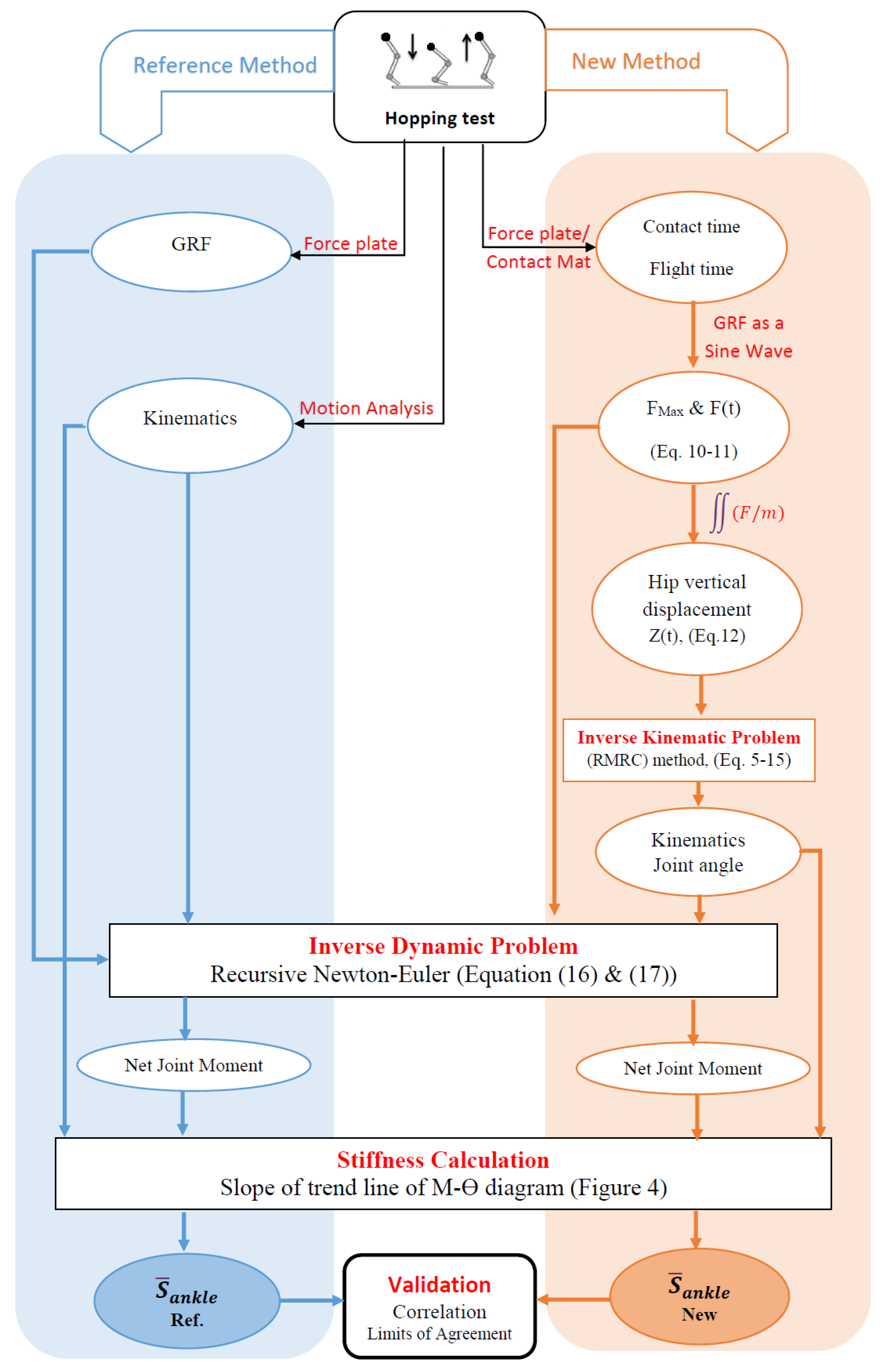
2.2. Calculating AJS Using New Method
2.3. Calculating AJS Based on Conventional (Reference) Method
2.4. Statistics
3. Results
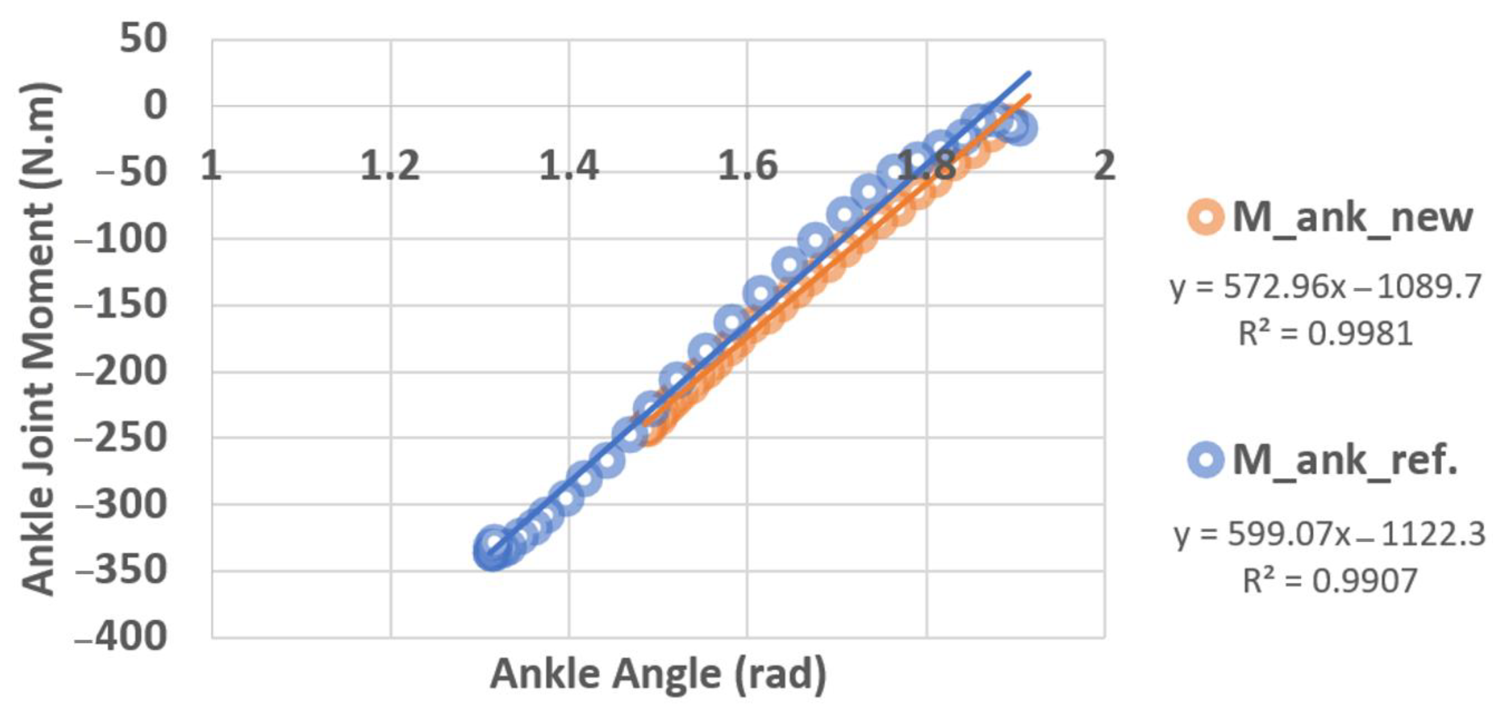
3.1. Methods Output
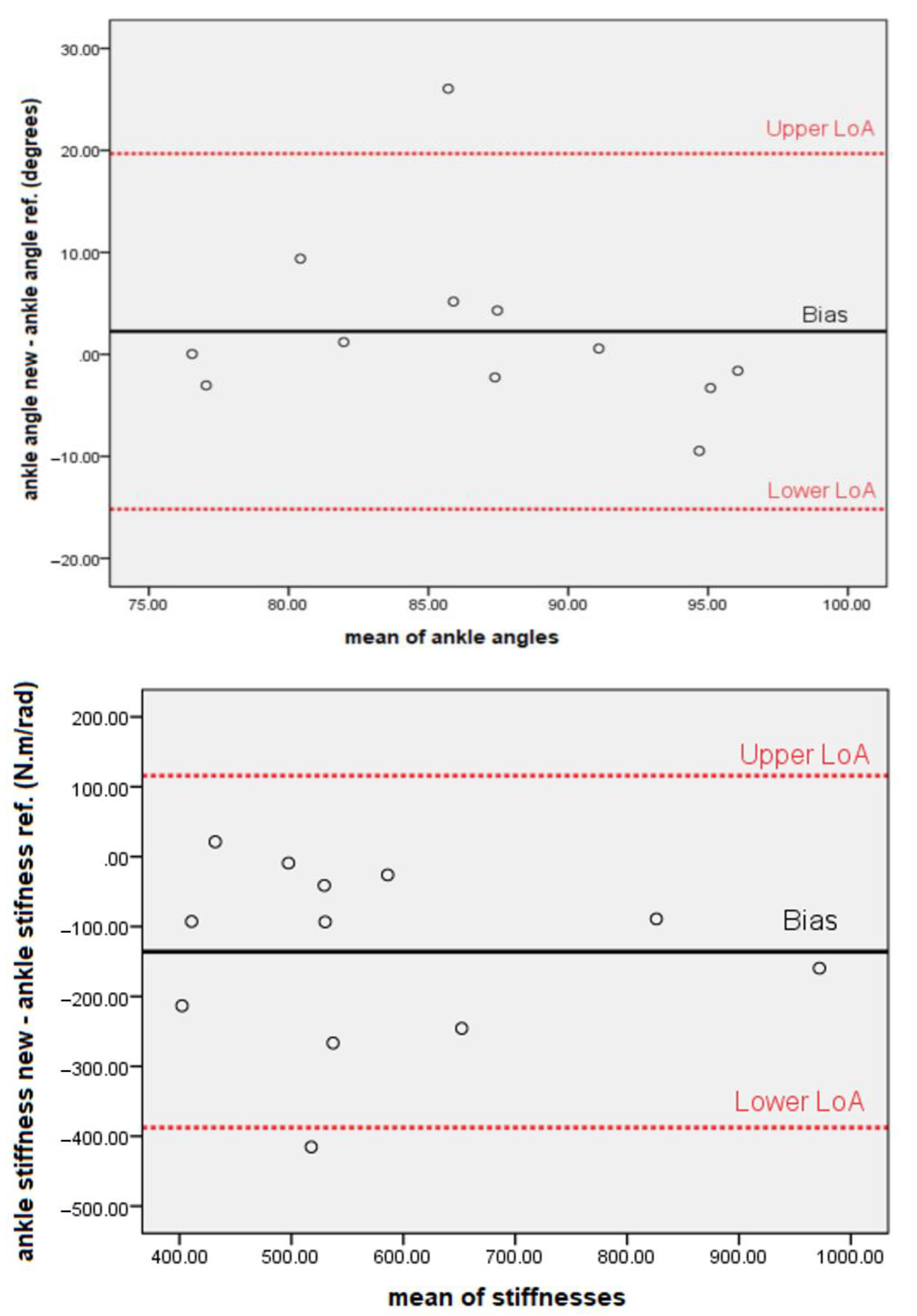
3.2. Validation
4. Discussion
5. Conclusions
Author Contributions
Funding
Institutional Review Board Statement
Informed Consent Statement
Data Availability Statement
Conflicts of Interest
Nomenclature
| AJS | Ankle joint stiffness |
| GRF | Ground reaction force |
| GT | Greater trochanter |
| LFE | Lateral femoral epicondyle |
| LM | Lateral malleolus |
| 5thMTP | Fifth metatarsophalangeal joint |
| RMRC | Resolved motion rate control |
| LoA | Limits of agreement |
| CoM | Center of mass |
| Joint angle | |
| l | Segment length |
| J | Jacobian matrix |
| m | Mass of subject |
| Gravitational acceleration | |
| t | Time |
| Tc | Contact time |
| Tf | Flight time |
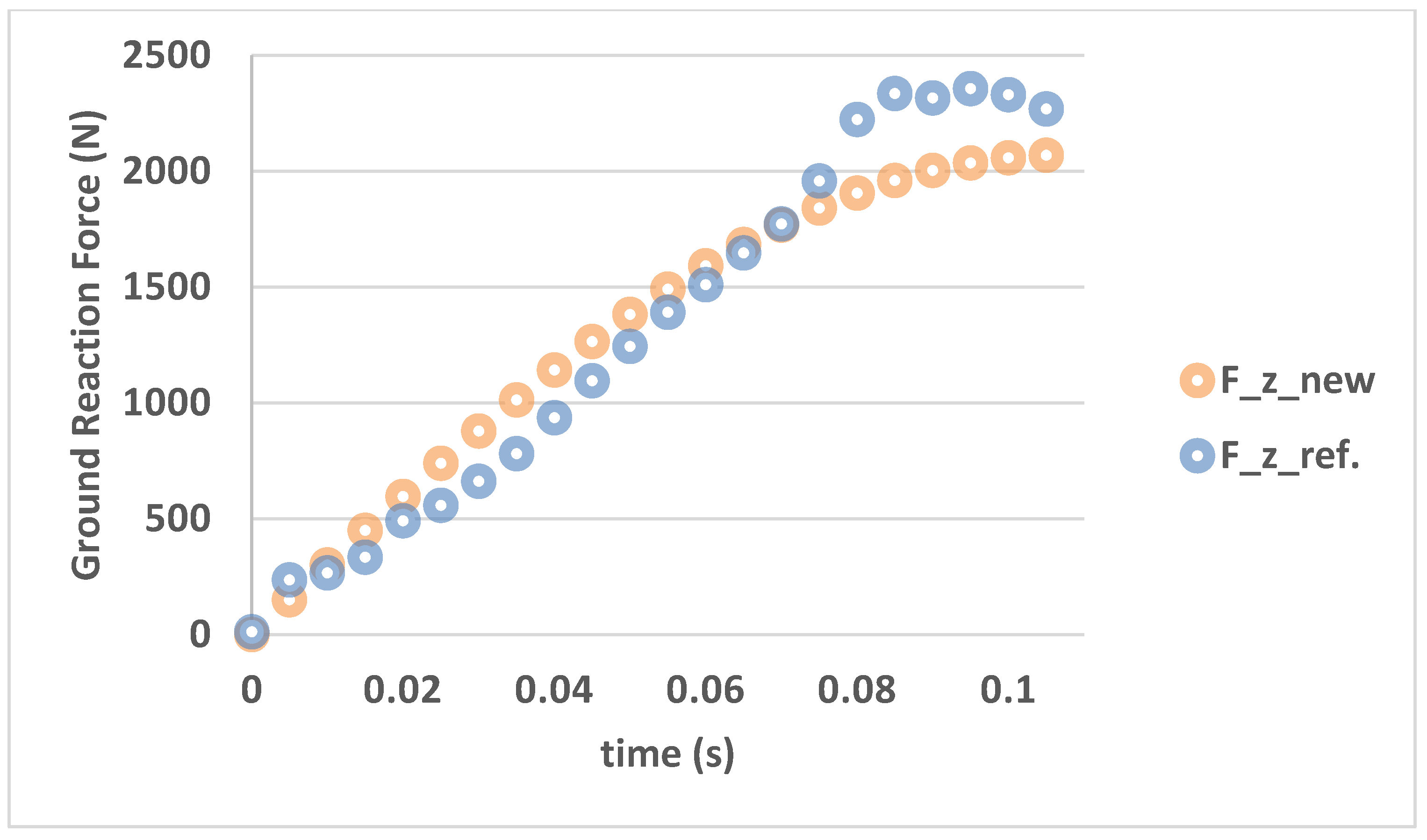
| F | Ground reaction force |
| Vertical linear velocity | |
| Linear velocity matrix | |
| z | Vertical displacement |
| Ɵ | Angular velocities |
| MP | Net moment at the proximal join |
| MD | Net moment at the distal join |
| FP | Net force at the proximal join |
| FD | Net force at the distal join |
| IG | Moment of inertia |
| aG | Linear acceleration about center of gravity |
| αG | Angular acceleration about center of gravity |
| rGP | Distance of proximal joint and center of gravity |
| rGD | Distance of distal joint and center of gravity |
| Angle of ankle | |
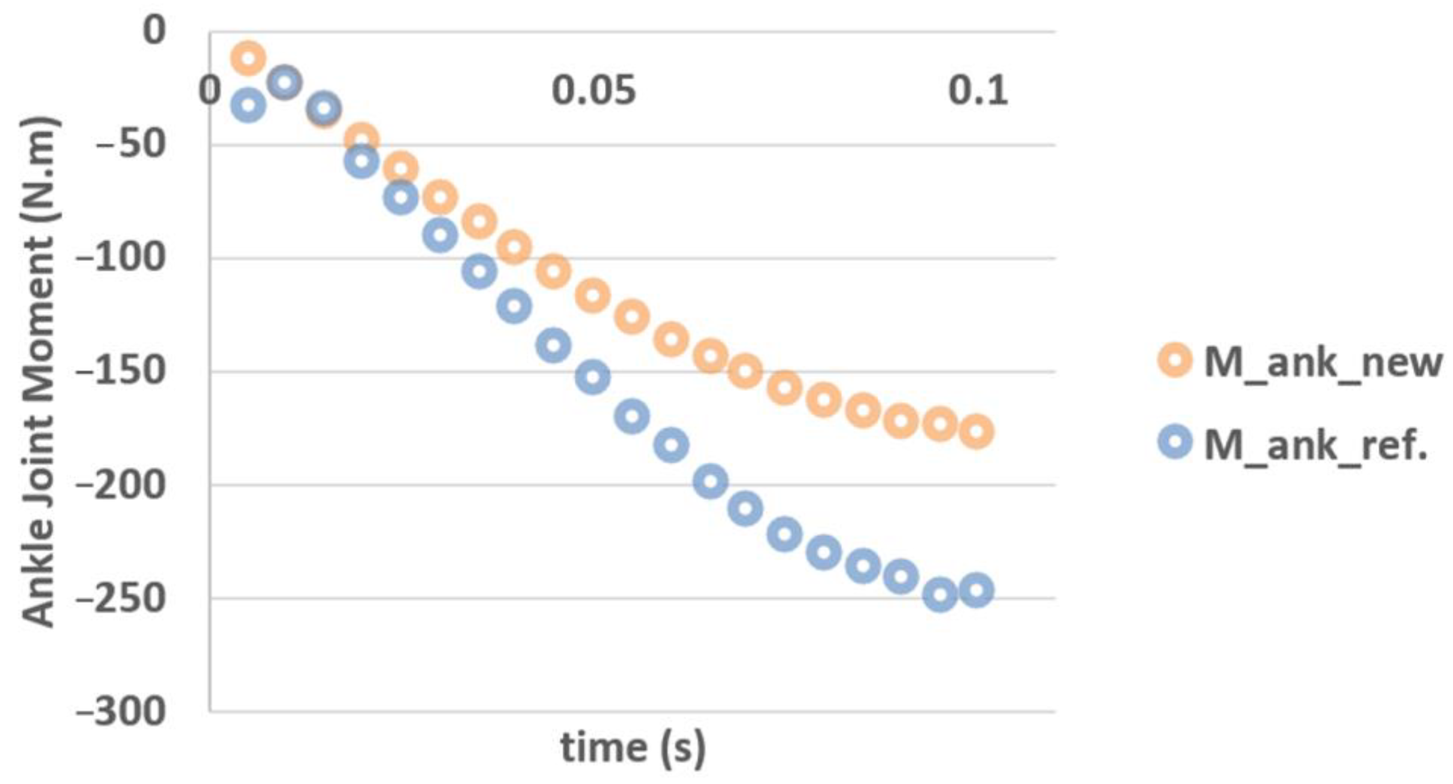
| M_ank_new | Net moment at ankle measured by new method |
| M_ank_ref | Net moment at ankle measured by reference method |
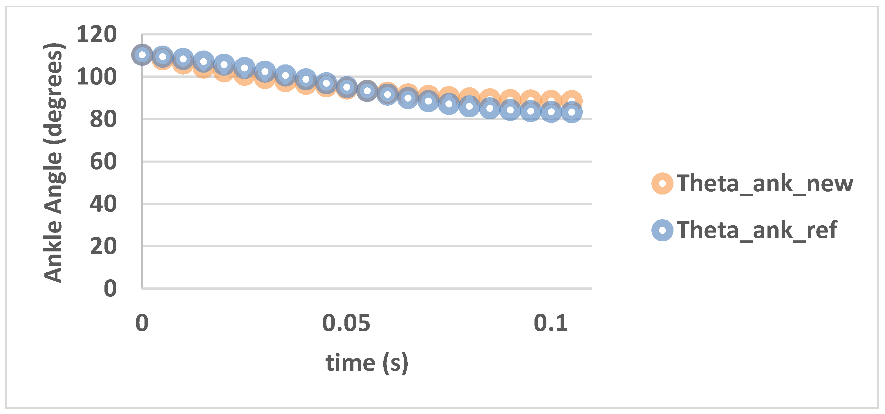
| Theta_ank_new | Angle of ankle measured by new method |
| Theta_ank_ref | Angle of ankle measured by reference method |
| Stiffness of ankle | |
| Stiffness of ankle measured by new method | |
| Stiffness of ankle measured by reference method | |
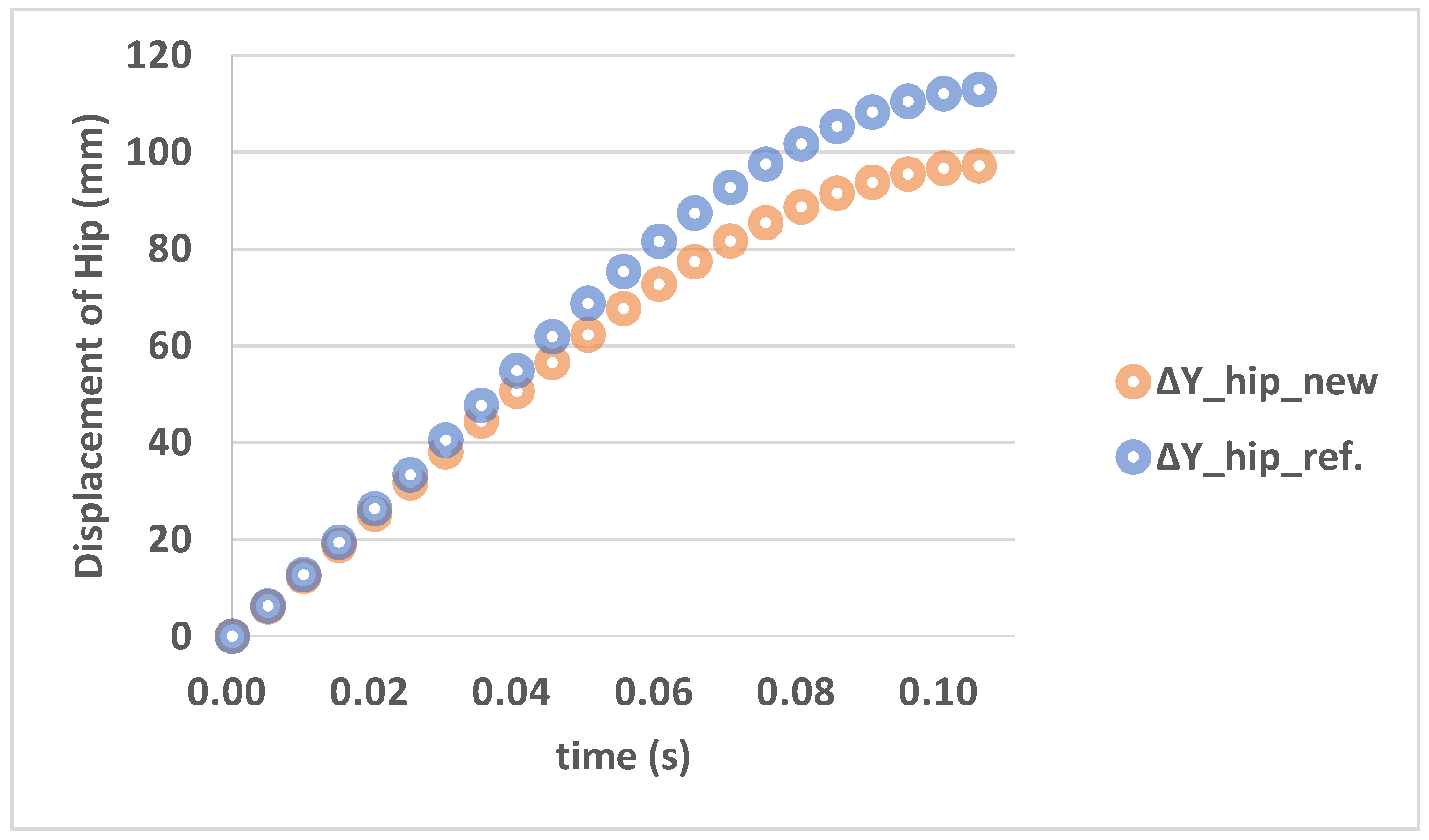
| deltaY_hip | Displacement of hip |
Appendix A

| Subject No. | ||
|---|---|---|
| 1 | 775.09 | 529.39 |
| 2 | 508.92 | 295.57 |
| 3 | 421.29 | 442.55 |
| 4 | 1051.7 | 892.07 |
| 5 | 599.07 | 572.96 |
| 6 | 670.58 | 403.91 |
| 7 | 549.97 | 508.79 |
| 8 | 870.69 | 781.68 |
| 9 | 576.78 | 483.52 |
| 10 | 457.18 | 364.4 |
| 11 | 502 | 492.81 |
| 12 | 725.46 | 310.07 |
References
- Baumgart, F. Stiffness—An unknown world of mechanical science? Injury 2000, 31, 14–84. [Google Scholar]
- Latash, M.L.; Zatsiorsky, V.M. Joint stiffness: Myth or reality? Hum. Mov. Sci. 1993, 12, 653–692. [Google Scholar] [CrossRef]
- Farley, C.T.; Houdijk, H.H.P.; Strien, C.V.; Louie, M. Mechanism of leg stiffness adjustment for hopping on surfaces of different stiffnesses. J. Appl. Physiol. 1998, 85, 1044–1055. [Google Scholar] [CrossRef]
- Farley, C.T.; Morgenroth, D.C. Leg stiffness primarily depends on ankle stiffness during human hopping. J. Biomech. 1999, 32, 267–273. [Google Scholar] [CrossRef]
- Stefanyshyn, D.J.; Nigg, B.M. Dynamic Angular Stiffness of the Ankle Joint during Running and Sprinting. J. Appl. Biomech. 1998, 14, 292–299. [Google Scholar] [CrossRef] [PubMed]
- Luo, Z.; Zhang, X.; Wang, J.; Yang, Y.; Xu, Y.; Fu, W. Changes in Ground Reaction Forces, Joint Mechanics, and Stiffness during Treadmill Running to Fatigue. Appl. Sci. 2019, 9, 5493. [Google Scholar] [CrossRef] [Green Version]
- Misgeld, B.J.E.; Zhang, T.; Lüken, M.J.; Leonhardt, S. Model-Based Estimation of Ankle Joint Stiffness. Sensors 2017, 17, 713. [Google Scholar] [CrossRef] [PubMed] [Green Version]
- Serpell, B.G.; Ball, N.B.; Scarvell, J.M.; Smith, P.N. A review of models of vertical, leg, and knee stiffness in adults for running, jumping or hopping tasks. J. Sports Sci. 2012, 30, 1347–1363. [Google Scholar] [CrossRef]
- Kuitunen, S.; Ogiso, K.; Komi, P.V. Leg and joint stiffness in human hopping. Scand. J. Med. Sci. Sports 2011, 21, e159–e167. [Google Scholar] [CrossRef] [PubMed]
- Maloney, S.J.; Fletcher, I.M. Lower limb stiffness testing in athletic performance: A critical review. Sports Biomech. 2018, 109–130. [Google Scholar] [CrossRef] [Green Version]
- Aleixo, P.; Vaz-Patto, J.; Moreira, H.; Abrantes, J. Dynamic joint stiffness of the ankle in healthy and rheumatoid arthritis post-menopausal women. Gait Posture 2018, 60, 225–234. [Google Scholar] [CrossRef]
- Iversen, M.D.; Weidenhielm-Broström, E.; Wang, R.; Esbjörnsson, A.-C.; Hagelberg, S.; Åstrand, P. Self-rated walking disability and dynamic ankle joint stiffness in children and adolescents with Juvenile Idiopathic Arthritis receiving intraarticular corticosteroid joint injections of the foot. Gait Posture 2019, 67, 257–261. [Google Scholar] [CrossRef]
- Brughelli, M.; Cronin, J. A review of research on the mechanical stiffness in running and jumping: Methodology and implications. Scand. J. Med. Sci. Sports 2008, 18, 417–426. [Google Scholar] [CrossRef] [PubMed]
- Brughelli, M.; Cronin, J. Influence of Running Velocity on Vertical, Leg and Joint Stiffness. Sports Med. 2008, 38, 647–657. [Google Scholar] [CrossRef] [PubMed]
- KUITUNEN, S.; Komi, P.V.; Kyröläinen, H. Knee and ankle joint stiffness in sprint running. Med. Sci. Sports Exerc. 2002, 34, 166–173. [Google Scholar] [CrossRef] [PubMed]
- Brazier, J.; Maloney, S.; Bishop, C.; Read, P.; Turner, A. Lower Extremity Stiffness: Considerations for Testing, Performance Enhancement, and Injury Risk. J Strength Cond Res 2019, 33, 1156–1166. [Google Scholar] [CrossRef] [PubMed] [Green Version]
- Lorimer, A.V.; Keogh, J.W.L.; Hume, P.A. Using stiffness to assess injury risk: Comparison of methods for quantifying stiffness and their reliability in triathletes. PeerJ 2018, 6, e5845. [Google Scholar] [CrossRef]
- Kim, H.; Cho, S.; Lee, H. Reliability of Bi-Axial Ankle Stiffness Measurement in Older Adults. Sensors 2021, 21, 1162. [Google Scholar] [CrossRef] [PubMed]
- Rapoport, S.; Mizrahi, J.; Kimmel, E.; Verbitsky, O.; Isakov, E. Constant and Variable Stiffness and Damping of the Leg Joints in Human Hopping. J. Biomech. Eng. 2003, 125, 507–514. [Google Scholar] [CrossRef]
- Bret, C.; Rahmani, A.; Dufour, A.-B.; Messonnier, L.; Lacour, J.R. Leg strength and stiffness as ability factors in 100-m sprint running. J. Sports Med. Phys. Fit. 2002, 42, 274–281. [Google Scholar]
- Hobara, H.; Kimura, K.; Omuro, K.; Gomi, K.; Muraoka, T.; Iso, S.; Kanosue, K. Determinants of difference in leg stiffness between endurance- and power-trained athletes. J. Biomech. 2008, 41, 506–514. [Google Scholar] [CrossRef]
- Hobara, H.; Inoue, K.; Muraoka, T.; Omuro, K.; Sakamoto, M.; Kanosue, K. Leg stiffness adjustment for a range of hopping frequencies in humans. J. Biomech. 2010, 43, 506–511. [Google Scholar] [CrossRef]
- Garofolini, A.; Taylor, S.; Mclaughlin, P.; Mickle, K.J.; Frigo, C.A. Ankle Joint Dynamic Stiffness in Long-Distance Runners: Effect of Foot Strike and Shoes Features. Appl. Sci. 2019, 9, 4100. [Google Scholar] [CrossRef] [Green Version]
- Kubo, K.; Morimoto, M.; Komuro, T.; Yata, H.; Tsunoda, N.; Kanehisa, H.; Fukunaga, T. Effects of plyometric and weight training on muscle-tendon complex and jump performance. Med. Sci. Sports Exerc. 2007, 39, 1801–1810. [Google Scholar] [CrossRef] [PubMed]
- Dalleau, G. A simple method for field measurements of leg stiffness in hopping. Int. J. Sports Med. 2004, 25, 170–176. [Google Scholar] [PubMed]
- Farley, C.T.; Blickhan, R.; Saito, J.; Taylor, C.R. Hopping frequency in humans: A test of how springs set stride frequency in bouncing gaits. J. Appl. Physiol. 1991, 71, 2127–2132. [Google Scholar] [CrossRef] [PubMed]
- Craig, J.J. Introduction to Robotics, Mechanics and Control, 3rd ed.; Pearson Education: Upper Saddle River, NJ, USA, 2005. [Google Scholar]
- Whitney, D.E. Resolved Motion Rate Control of Manipulators and Human Prostheses. IEEE Trans. Man-Mach. Syst. 1969, 10, 47–53. [Google Scholar] [CrossRef]
- Zatsiorsky, V.M. Kinetics of Human Motion; Human Kinetics: Champaign, IL, USA, 2002. [Google Scholar]
- Chino, K.; Takahashi, H. Measurement of gastrocnemius muscle elasticity by shear wave elastography: Association with passive ankle joint stiffness and sex differences. Eur. J. Appl. Physiol. 2016, 116, 823–830. [Google Scholar] [CrossRef]
- Hobara, H.; Baum, B.S.; Kwon, H.-J.; Miller, R.H.; Ogata, T.; Kim, Y.H.; Shim, J.K. Amputee locomotion: Spring-like leg behavior and stiffness regulation using running-specific prostheses. J. Biomech. 2013, 46, 2483–2489. [Google Scholar] [CrossRef] [Green Version]
- Ashrostaghi, M. The Relationship of Mechanical Stiffness during Hopping Test with Performance and Injury Risk Factors of Lower Extremity in Selected Fundamental Movement Skills. Ph.D. Thesis, Kharazmi University, Tehran, Iran, 2016. (In Persian). [Google Scholar]
- McLachlan, K.A.; Murphy, A.J.; Watsford, M.L.; Rees, S. The Interday Reliability of Leg and Ankle Musculotendinous Stiffness Measures. J. Appl. Biomech. 2006, 22, 296–304. [Google Scholar] [CrossRef] [PubMed] [Green Version]
- Cavagna, G.A.; Franzetti, P.; Heglund, N.C.; Willems, P. The determinants of the step frequency in running, trotting and hopping in man and other vertebrates. J. Physiol. 1988, 399, 81–92. [Google Scholar] [CrossRef] [PubMed]
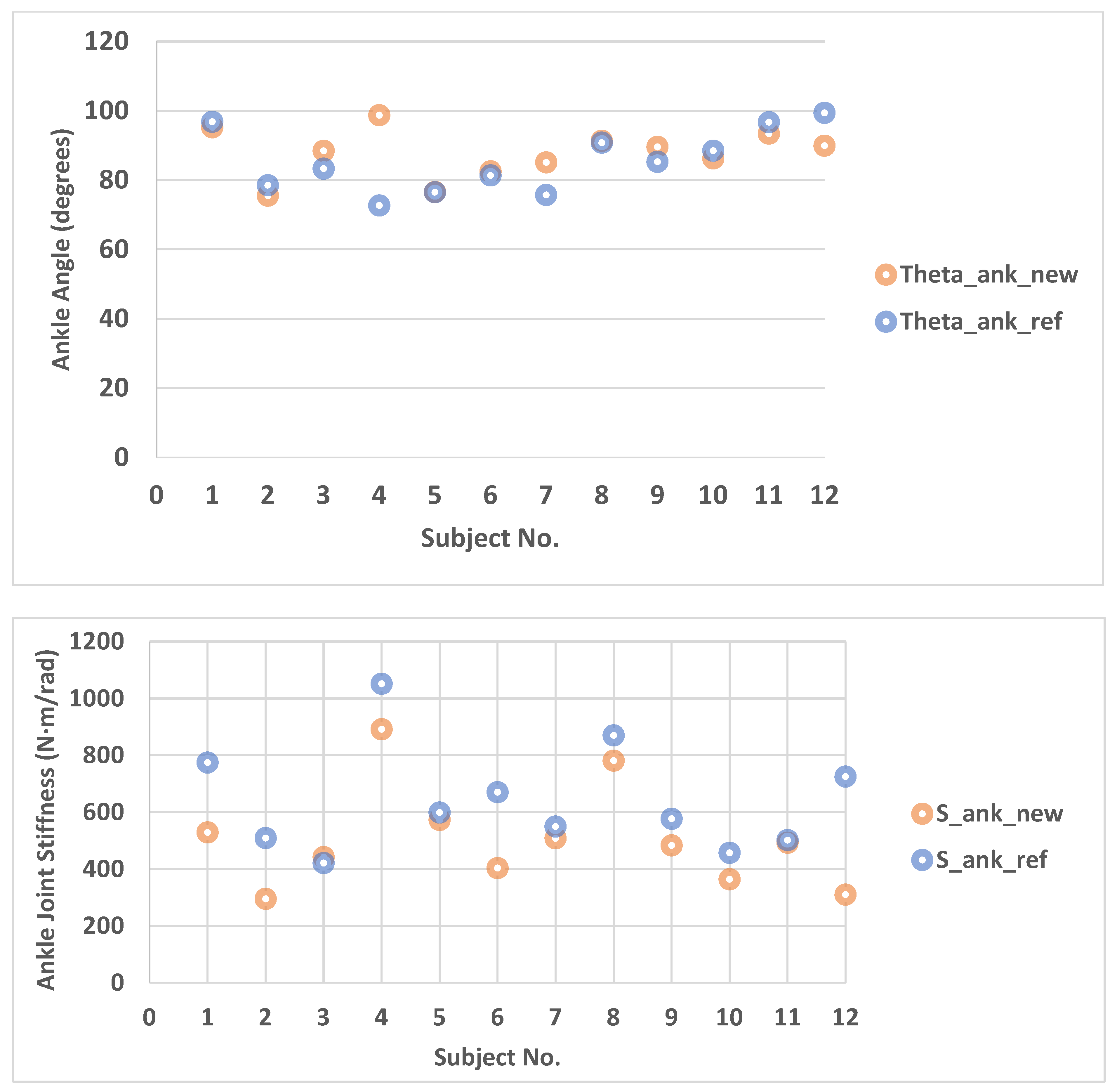
| Min. | Max. | Mean | SD | Test of Normality (Shapiro–Wilk Sig.) | ||
|---|---|---|---|---|---|---|
(degrees) | 72.68 | 99.41 | 85.48 | 9.02 | 0.532 | |
| 75.53 | 98.73 | 87.74 | 7.01 | 0.822 | ||
(N·m/rad) | 421.29 | 1051.70 | 642.39 | 185.96 | 0.322 | |
| 295.57 | 892.07 | 506.47 | 177.84 | 0.145 |
Publisher’s Note: MDPI stays neutral with regard to jurisdictional claims in published maps and institutional affiliations. |
© 2021 by the authors. Licensee MDPI, Basel, Switzerland. This article is an open access article distributed under the terms and conditions of the Creative Commons Attribution (CC BY) license (https://creativecommons.org/licenses/by/4.0/).
Share and Cite
Ghorbani Faal, S.; Shirzad, E.; Sharifnezhad, A.; Ashrostaghi, M.; Naemi, R. A Novel Method for Field Measurement of Ankle Joint Stiffness in Hopping. Appl. Sci. 2021, 11, 12140. https://doi.org/10.3390/app112412140
Ghorbani Faal S, Shirzad E, Sharifnezhad A, Ashrostaghi M, Naemi R. A Novel Method for Field Measurement of Ankle Joint Stiffness in Hopping. Applied Sciences. 2021; 11(24):12140. https://doi.org/10.3390/app112412140
Chicago/Turabian StyleGhorbani Faal, Sanubar, Elham Shirzad, Ali Sharifnezhad, Mojtaba Ashrostaghi, and Roozbeh Naemi. 2021. "A Novel Method for Field Measurement of Ankle Joint Stiffness in Hopping" Applied Sciences 11, no. 24: 12140. https://doi.org/10.3390/app112412140
APA StyleGhorbani Faal, S., Shirzad, E., Sharifnezhad, A., Ashrostaghi, M., & Naemi, R. (2021). A Novel Method for Field Measurement of Ankle Joint Stiffness in Hopping. Applied Sciences, 11(24), 12140. https://doi.org/10.3390/app112412140