
Pull-Out Capability of a 3D Printed Threadless Suture Anchor with Rectangular Cross-Section: A Biomechanical Study

 ,
,
Abstract
:1. Introduction
2. Materials and Methods
3. Results
4. Discussion
5. Conclusions
Author Contributions
Funding
Institutional Review Board Statement
Informed Consent Statement
Data Availability Statement
Conflicts of Interest
References
- Green, J.L.; Ruppert, D.; Glisson, R.; Ibrahim, M.; Gall, K.; Levinson, H.; Ibrahim, M. Application of a novel suture anchor to abdominal wall closure. Am. J. Surg. 2019, 218, 1–6. [Google Scholar] [CrossRef]
- Visscher, L.E.; Jeffery, C.; Gilmour, T.; Anderson, L.; Couzens, G. The history of suture anchors in orthopaedic surgery. Clin. Biomech. 2019, 61, 70–78. [Google Scholar] [CrossRef] [PubMed] [Green Version]
- Philippon, M.J.; Faucet, S.C.; Briggs, K.K. Arthroscopic Hip Labral Repair. Arthrosc. Tech. 2013, 2, e73–e76. [Google Scholar] [CrossRef] [PubMed]
- Silver, M.D.; Daigneault, J.P. Symptomatic interarticular migration of glenoid suture anchors. Arthrosc. J. Arthrosc. Relat. Surg. 2000, 16, 102–105. [Google Scholar] [CrossRef]
- Kaar, T.; Schenck, R.C.; Wirth, M.A.; Rockwood, C.A. Complications of metallic suture anchors in shoulder surgery. Arthrosc. J. Arthrosc. Relat. Surg. 2001, 17, 31–37. [Google Scholar] [CrossRef] [PubMed]
- Djurasovic, M.; Marra, G.; Arroyo, J.S.; Pollock, R.G.; Flatow, E.L.; Bigliani, L.U. Revision Rotator Cuff Repair: Factors Influencing Results. J. Bone Jt. Surg. -Am. Vol. 2001, 83, 1849–1855. [Google Scholar] [CrossRef]
- MacBarb, R.F.; Lindsey, D.P.; Woods, S.A.; Lalor, P.A.; Gundanna, M.I.; Yerby, S.A. Fortifying the Bone-Implant Interface Part 2: An In Vivo Evaluation of 3D-Printed and TPS-Coated Triangular Implants. Int. J. Spine Surg. 2017, 11, 16. [Google Scholar] [CrossRef] [Green Version]
- Patel, V.; Kovalsky, D.; Meyer, S.C.; Chowdhary, A.; Lockstadt, H.; Techy, F.; Langel, C.; Limoni, R.; Yuan, P.S.; Kranenburg, A.; et al. Prospective Trial of Sacroiliac Joint Fusion Using 3D-Printed Triangular Titanium Implants. Med. Devices Evid. Res. 2020, 13, 173–182. [Google Scholar] [CrossRef]
- Wei, W.; Ali, K.; Yang, H.; Nassab, R.; Shahriyari, F.; Akpek, A.; Guan, X.; Liu, Y.; Taranejoo, S.; Tamayol, A.; et al. 3D Printed Anchoring Sutures for Permanent Shaping of Tissues. Macromol. Biosci. 2017, 17, 1700304. [Google Scholar] [CrossRef] [PubMed]
- Ntalos, D.; Huber, G.; Sellenschloh, K.; Saito, H.; Püschel, K.; Morlock, M.M.; Frosch, K.H.; Klatte, T.O. All-suture anchor pullout results in decreased bone damage and depends on cortical thickness. Knee Surg. Sports Traumatol. Arthrosc. 2020, 29, 2212–2219. [Google Scholar] [CrossRef] [Green Version]
- Barber, F.A.; Hapa, O.; Bynum, J.A. Comparative Testing by Cyclic Loading of Rotator Cuff Suture Anchors Containing Multiple High-Strength Sutures. Arthrosc. J. Arthrosc. Relat. Surg. 2010, 26, S134–S141. [Google Scholar] [CrossRef]
- Bynum, C.K.; Lee, S.; Mahar, A.; Tasto, J.; Pedowitz, R. Failure Mode of Suture Anchors as a Function of Insertion Depth. Am. J. Sports Med. 2005, 33, 1030–1034. [Google Scholar] [CrossRef]
- De Carli, A.; Vadalà, A.; Monaco, E.; Labianca, L.; Zanzotto, E.; Ferretti, A. Effect of Cyclic Loading on New Polyblend Suture Coupled with Different Anchors. Am. J. Sports Med. 2005, 33, 214–219. [Google Scholar] [CrossRef] [PubMed]
- Nagamoto, H.; Yamamoto, N.; Itoi, E. Effect of anchor threads on the pullout strength: A biomechanical study. J. Orthop. 2018, 15, 878–881. [Google Scholar] [CrossRef]
- Nagamoto, H.; Yamamoto, N.; Sano, H.; Itoi, E. A biomechanical study on suture anchor insertion angle: Which is better, 90° or 45°? J. Orthop. Sci. 2017, 22, 56–62. [Google Scholar] [CrossRef] [PubMed]
- Tingart, M.J.; Bouxsein, M.L.; Zurakowski, D.; Warner, J.P.; Apreleva, M. Three-dimensional distribution of bone density in the proximal humerus. Calcif. Tissue Int. 2003, 73, 531–536. [Google Scholar] [CrossRef]
- Clevenger, T.A.; Beebe, M.; Strauss, E.; Kubiak, E.N. The Effect of Insertion Angle on the Pullout Strength of Threaded Suture Anchors: A Validation of the Deadman Theory. Arthrosc. J. Arthrosc. Relat. Surg. 2014, 30, 900–905. [Google Scholar] [CrossRef]
- Liporace, F.A.; Bono, C.M.; Caruso, S.A.; Weiner, B.; Penny, K.; Feldman, A.J.; Grossman, M.G.; Haher, T.R. The Mechanical Effects of Suture Anchor Insertion Angle for Rotator Cuff Repair. Orthopedics 2002, 25, 399–402. [Google Scholar] [CrossRef] [PubMed]
- Barber, F.A.; Herbert, M.A. Cyclic Loading Biomechanical Analysis of the Pullout Strengths of Rotator Cuff and Glenoid Anchors: 2013 Update. Arthrosc. J. Arthrosc. Relat. Surg. 2013, 29, 832–844. [Google Scholar] [CrossRef]
- Cho, C.-H.; Bae, K.-C.; Kim, D.-H. Biomaterials Used for Suture Anchors in Orthopedic Surgery. Clin. Orthop. Surg. 2021, 13, 287–292. [Google Scholar] [CrossRef]
- Barber, F.A. Complications of Biodegradable Materials. Sports Med. Arthrosc. Rev. 2015, 23, 149–155. [Google Scholar] [CrossRef]
- Noiset, O.; Schneider, Y.-J.; Marchand-Brynaert, J. Fibronectin adsorption or/and covalent grafting on chemically modified PEEK film surfaces. J. Biomater. Sci. Polym. Ed. 1999, 10, 657–677. [Google Scholar] [CrossRef]
- Toth, J.M.; Wang, M.; Estes, B.; Scifert, J.L.; Seim, H.B.; Turner, A.S. Polyetheretherketone as a biomaterial for spinal applications. Biomaterials 2006, 27, 324–334. [Google Scholar] [CrossRef] [Green Version]
- Green, R.N.; Donaldson, O.W.; Dafydd, M.; Evans, S.; Kulkarni, R. Biomechanical Study: Determining the Optimum Insertion Angle for Screw-In Suture Anchors—Is Deadman’s Angle Correct? Arthrosc. J. Arthrosc. Relat. Surg. 2014, 30, 1535–1539. [Google Scholar] [CrossRef] [PubMed]
- Strauss, E.; Frank, D.; Kubiak, E.; Kummer, F.; Rokito, A. The Effect of the Angle of Suture Anchor Insertion on Fixation Failure at the Tendon–Suture Interface after Rotator Cuff Repair: Deadman’s Angle Revisited. Arthrosc. J. Arthrosc. Relat. Surg. 2009, 25, 597–602. [Google Scholar] [CrossRef] [PubMed]
- Kohli, N.; Stoddart, J.C.; van Arkel, R.J. The limit of tolerable micromotion for implant osseointegration: A systematic review. Sci. Rep. 2021, 11, 1–11. [Google Scholar] [CrossRef]
- Sturesson, B.; Kools, D.; Pflugmacher, R.; Gasbarrini, A.; Prestamburgo, D.; Dengler, J. Six-month outcomes from a randomized controlled trial of minimally invasive SI joint fusion with triangular titanium implants vs. conservative management. Eur. Spine J. 2017, 26, 708–719. [Google Scholar] [CrossRef] [PubMed] [Green Version]
- INSITE Study Group; Polly, D.W.; Cher, D.J.; Wine, K.D.; Whang, P.G.; Frank, C.J.; Harvey, C.F.; Lockstadt, H.; Glaser, J.A.; Limoni, R.P.; et al. Randomized Controlled Trial of Minimally Invasive Sacroiliac Joint Fusion Using Triangular Titanium Implants vs. Nonsurgical Management for Sacroiliac Joint Dysfunction. Neurosurgery 2015, 77, 674–691. [Google Scholar] [CrossRef] [Green Version]
- Dengler, J.; Kools, D.; Pflugmacher, R.; Gasbarrini, A.; Prestamburgo, D.; Gaetani, P.; Cher, D.; Van Eeckhoven, E.; Annertz, M.; Sturesson, B. Randomized Trial of Sacroiliac Joint Arthrodesis Compared with Conservative Management for Chronic Low Back Pain Attributed to the Sacroiliac Joint. J. Bone Jt. Surg.-Am. Vol. 2019, 101, 400–411. [Google Scholar] [CrossRef]
- Fukuda, A.; Takemoto, M.; Saito, T.; Fujibayashi, S.; Neo, M.; Pattanayak, D.K.; Matsushita, T.; Sasaki, K.; Nishida, N.; Kokubo, T.; et al. Osteoinduction of porous Ti implants with a channel structure fabricated by selective laser melting. Acta Biomater. 2011, 7, 2327–2336. [Google Scholar] [CrossRef]
- Taniguchi, N.; Fujibayashi, S.; Takemoto, M.; Sasaki, K.; Otsuki, B.; Nakamura, T.; Matsushita, T.; Kokubo, T.; Matsuda, S. Effect of pore size on bone ingrowth into porous titanium implants fabricated by additive manufacturing: An in vivo experiment. Mater. Sci. Eng. C 2016, 59, 690–701. [Google Scholar] [CrossRef] [PubMed] [Green Version]


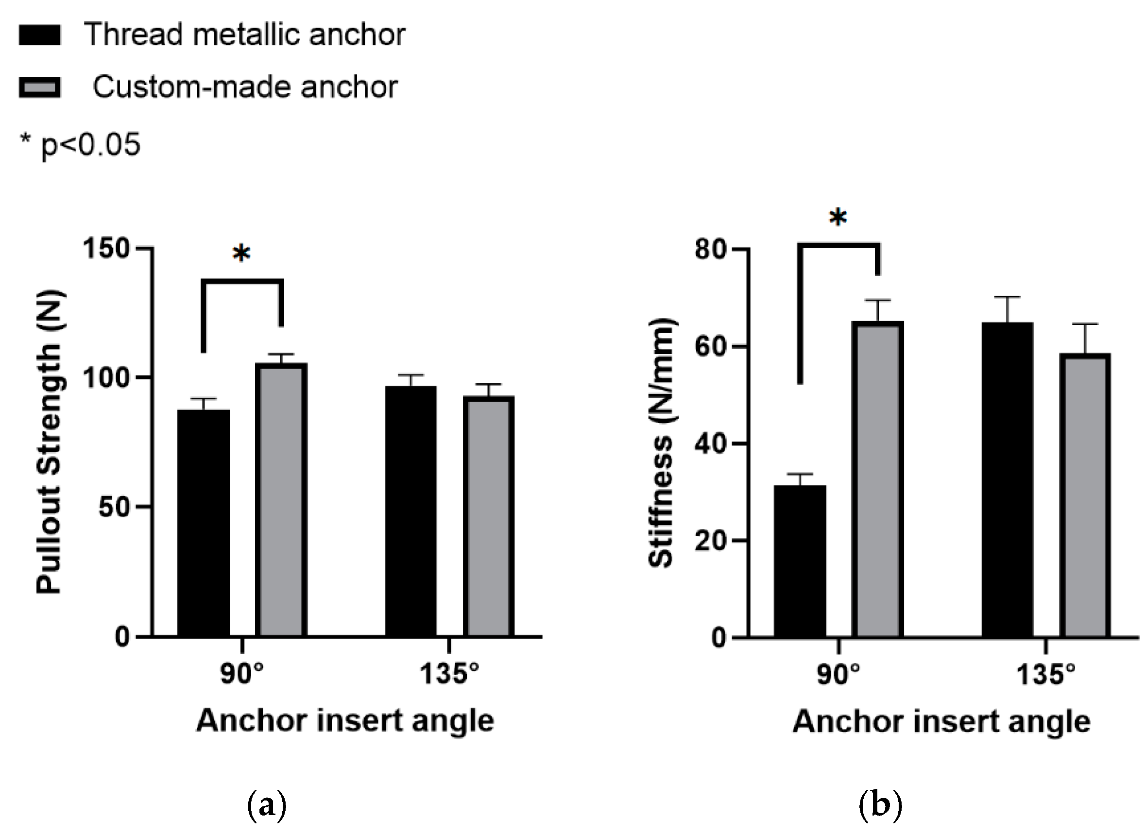
| Mean Pullout Strength N, (SD) | Mean Pullout Stiffness N/mm, (SD) | |||
|---|---|---|---|---|
| 90° Insertion Angle | 135° Insertion Angle | 90° Insertion Angle | 135° Insertion Angle | |
| Thread metallic suture anchor | 87.9 (4.1) | 96.8 (4.3) | 31.3 (2.3) | 64.9 (5.3) |
| Custom-made suture anchor | 105.6 (3.5) | 92.9 (4.5) | 65.2 (4.3) | 58.6 (5.9) |
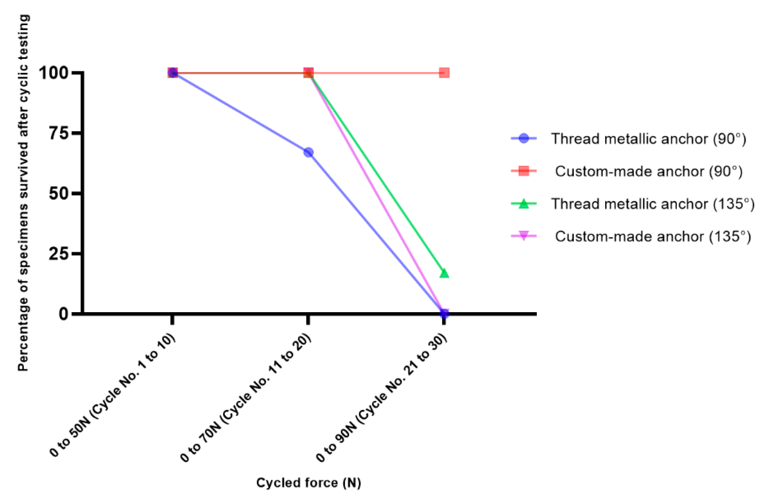
| 90° Insertion Angle | 135° Insertion Angle | |||||
|---|---|---|---|---|---|---|
| Cycle No. | 1 to 10 | 11 to 20 | 21 to 30 | 1 to 10 | 11 to 20 | 21 to 30 |
| Cycled force (N) | 0 to 50 | 0 to 70 | 0 to 90 | 0 to 50 | 0 to 70 | 0 to 90 |
| Thread metallic suture anchor | 100% | 67% | 0% | 100% | 100% | 17% |
| Custom-made suture anchor | 100% | 100% | 100% | 100% | 100% | 0% |
Publisher’s Note: MDPI stays neutral with regard to jurisdictional claims in published maps and institutional affiliations. |
© 2021 by the authors. Licensee MDPI, Basel, Switzerland. This article is an open access article distributed under the terms and conditions of the Creative Commons Attribution (CC BY) license (https://creativecommons.org/licenses/by/4.0/).
Share and Cite
Hsieh, Y.-Y.; Wu, L.-C.; Tsuang, F.-Y.; Chen, C.-H.; Chiang, C.-J. Pull-Out Capability of a 3D Printed Threadless Suture Anchor with Rectangular Cross-Section: A Biomechanical Study. Appl. Sci. 2021, 11, 12128. https://doi.org/10.3390/app112412128
Hsieh Y-Y, Wu L-C, Tsuang F-Y, Chen C-H, Chiang C-J. Pull-Out Capability of a 3D Printed Threadless Suture Anchor with Rectangular Cross-Section: A Biomechanical Study. Applied Sciences. 2021; 11(24):12128. https://doi.org/10.3390/app112412128
Chicago/Turabian StyleHsieh, Yueh-Ying, Lien-Chen Wu, Fon-Yih Tsuang, Chia-Hsien Chen, and Chang-Jung Chiang. 2021. "Pull-Out Capability of a 3D Printed Threadless Suture Anchor with Rectangular Cross-Section: A Biomechanical Study" Applied Sciences 11, no. 24: 12128. https://doi.org/10.3390/app112412128
APA StyleHsieh, Y.-Y., Wu, L.-C., Tsuang, F.-Y., Chen, C.-H., & Chiang, C.-J. (2021). Pull-Out Capability of a 3D Printed Threadless Suture Anchor with Rectangular Cross-Section: A Biomechanical Study. Applied Sciences, 11(24), 12128. https://doi.org/10.3390/app112412128