1. Introduction
In recent years, software development organizations must balance the need for high-quality software through diverse testing technologies [
1] and the need to make automatic test case generation and test execution from informal Korean requirements, which can reduce testing time and cost in more efficient testing endeavors [
2].
However, due to semantic analysis of requirements based on the Korean language [
1] in Korea, it is difficult to automatically generate test cases from informal requirements written with the Korean natural language. So, we are still holding on automatically generating test cases from informal natural Korean language-based requirement specifications. To do this, we suggest an automatic generation mechanism to extract cause-effect from requirements as follows: (1) simplify informal requirements, (2) extract Cause and Effect from them, (3) create C3Tree with the extracted Cause and Effects, (4) generate the cause-effect graph, (5) convert this graph into decision tables, and (6) finally generate test cases based on the decision tables.
Gary E. Mogyorodi [
3,
4] mentions that the Cause-Effect Graphing is a test case design technique that is performed once requirements have been reviewed for ambiguity, and the Cause-Effect Graphing technique derives the minimum number of test cases to cover 100% of functional requirements to improve the quality of test coverage. To automatically generate a Cause-Effect Graph from the requirements, we propose a method to simplify the structure of a requirement sentence, identify causes and effects in the simplified sentences, and create a Cause/Conjunction/Clause (C3Tree) Model to express the identified information, and transform C3Tree Model to Cause-Effect Graph Model. In this paper, we limit to describing the Cause-Effect Graph via Informal requirement specifications.
This paper is organized as follows.
Section 2 mentions related works.
Section 3 mentions the method of automatically generating Cause-Effect Graphs from the informal requirements.
Section 4 mentions our automatic generation mechanism of the Korean Requirements Analyzer for Cause-Effect Graph.
Section 5 mentions a case study using actual missile systems. Finally, the conclusion and future work are mentioned in
Section 6.
2. Related Studies
2.1. Cause-Effect Graph
To make the Cause-Effect Graph, they did mention identifying the smallest functional unit from the requirements specification, which defines the identified units as cause and effect, and pairs them [
3]. With Cause-Effect Graph, we can create the minimal test cases to include the maximal testing domain of software requirement, which reduces testing time and cost [
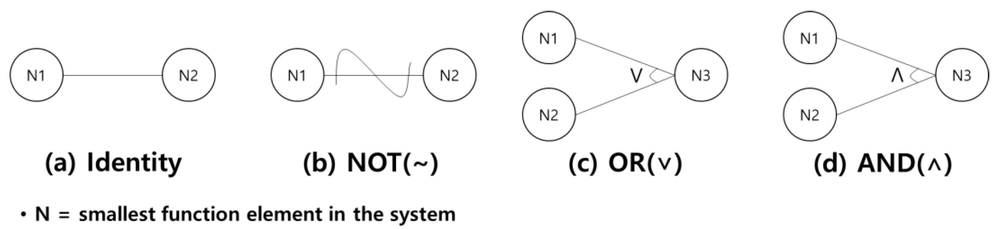
3]. Additionally, it can show a logical relationship between the input and output conditions with logical operators-AND, OR, and NOT shown in
Figure 1 [
5]. (a) means ’If N1 = true, then N2=true’. (b) means ’If N1 = false, then N2 = true’. (c) means ’If N1 = true or N2 = true, then N3 = true’. (d) means ’If N1 = true and N2 = true, then N3 = true’. The Left node represents “Cause” to show the input conditions, such as the changes within a system. On the contrary, The Right node indicates “Effect” to mean the output conditions, including the state which results from the combination of systematic transformation or causes.
Berk Bekirolu [
6] focused on testing with the cause-effect graph from English software specifications. Nobody does work with automatically generating Cause-Effect Graphs from the Korean requirements.
2.2. Model-Based Test Case Generation Research
Our previous research did follow Gary E. Mogyorodi’s approach, which mentioned 100% functional requirement coverage with the minimal test cases based on a Cause-Effect Graph [
3]. We focused on converting sequence diagrams into cause-effect graphs and then generating test cases with them. To automatically make test case generation, we adapted model transformations (such as model-to-model and model-to-text) among models (such as sequence diagram, cause-effect diagram, decision table, and test case) based on the meta-modeling approach [
7].
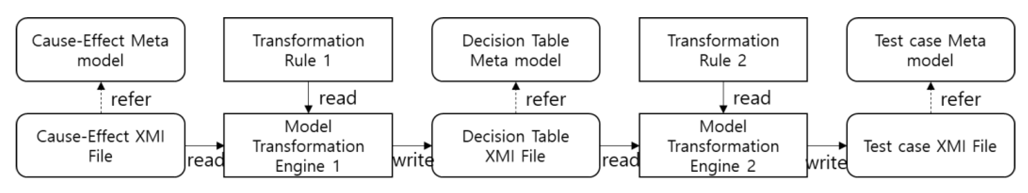
In other words, we transformed (1) a cause-effect graph into a decision table and (2) the decision table into a test case through the model transformation method, which implements the input and output data of the model transformation as all XML metadata exchange [
4]. This approach did not deal with informal requirement sentences.
Figure 2 shows this process of model transformations.
Each meta model stores meta information about the model (XMI File). The Cause-Effect Graph is automatically converted to the Decision Table by Model Transformation Engine 1 with Transformation Rule 1. Model Transformation Engine1 automatically converts the Cause-Effect Graph generated by referring to the Cause-Effect Meta model to the Decision Table created by the Decision Table Meta model. Likewise, the Decision Table is automatically converted into a Test case by Model Transformation Engine 2.
3. Automatic Generation Method of the Cause-Effect Graph from Informal Requirement Specifications
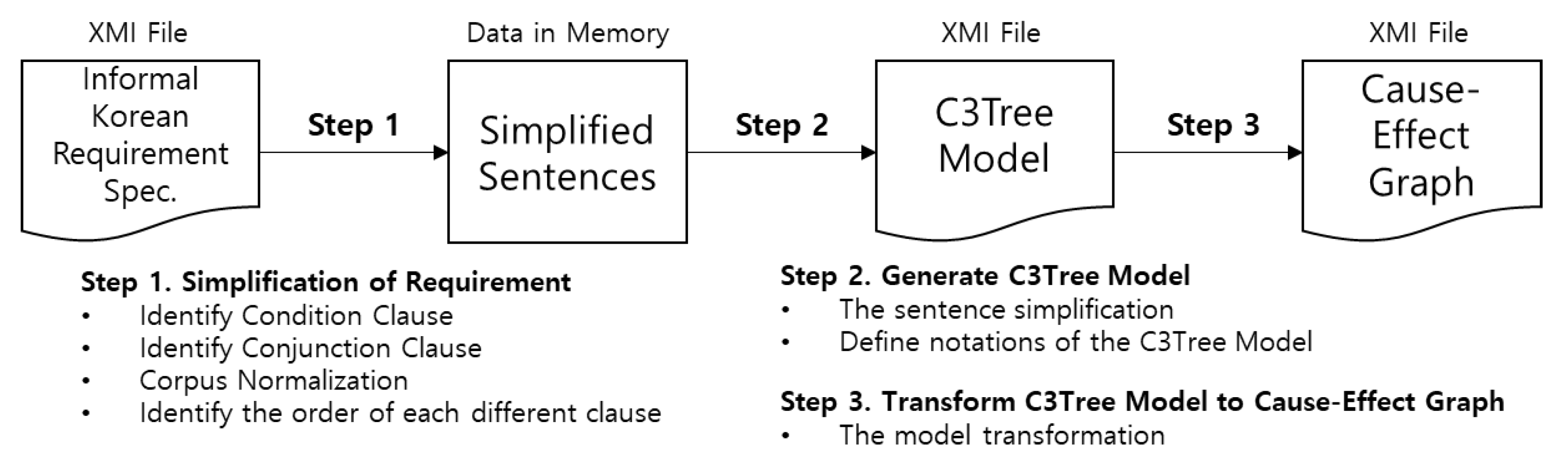
We show the process of a cause-effect graph generation from informal requirement specifications, as shown in
Figure 3. We offer the process of a cause-effect graph generation from informal requirement specifications as follows: (1) Informal Korean Requirement Specification as a text file, (2) the Simplified Sentences as program data in memory, (3) C3Tree Model as a simplified text model file, and (4) Cause-Effect Graph as an output model file, and Steps 1–3 as methods for generating each output.
In this process, we simplify the informal requirement sentence and express the C3Tree Model as the simplification. Finally, we represent the C3Tree Model as a Cause-Effect Graph.
3.1. Step 1. Simplify Complex Requirements
We identify the “Cause” node, “Effect” node with the “Identity” relationship, “NOT” relationship, “AND” relationship, and “OR” relationship between the cause and the effect node in natural language-based requirement sentences. Then we draw a Cause-Effect Graph using the identified information, placing the “Cause” node in the Condition clause and the “Effect” node in the Result clause of a natural language sentence. There exists the “AND” or “OR” relationship between a Conjunction clause and the Following clause nested from each “Cause” and “Effect” node. It can also place the “NOT” relationship in both the Condition clause and Result clause.
We use a morpheme analyzer to analyze the morpheme in a sentence, which identifies the types (condition, result, conjunction, and following) of the Clauses in the sentence included with the analyzed morphemes. The morpheme analyzer represents tags instead of part of speech (POS) to identify morphemes of the sentence.
Table 1 shows details of the tags of POS used in the morpheme analyzer.
3.1.1. Identify the Condition-Positive, Condition-Negative Relationship
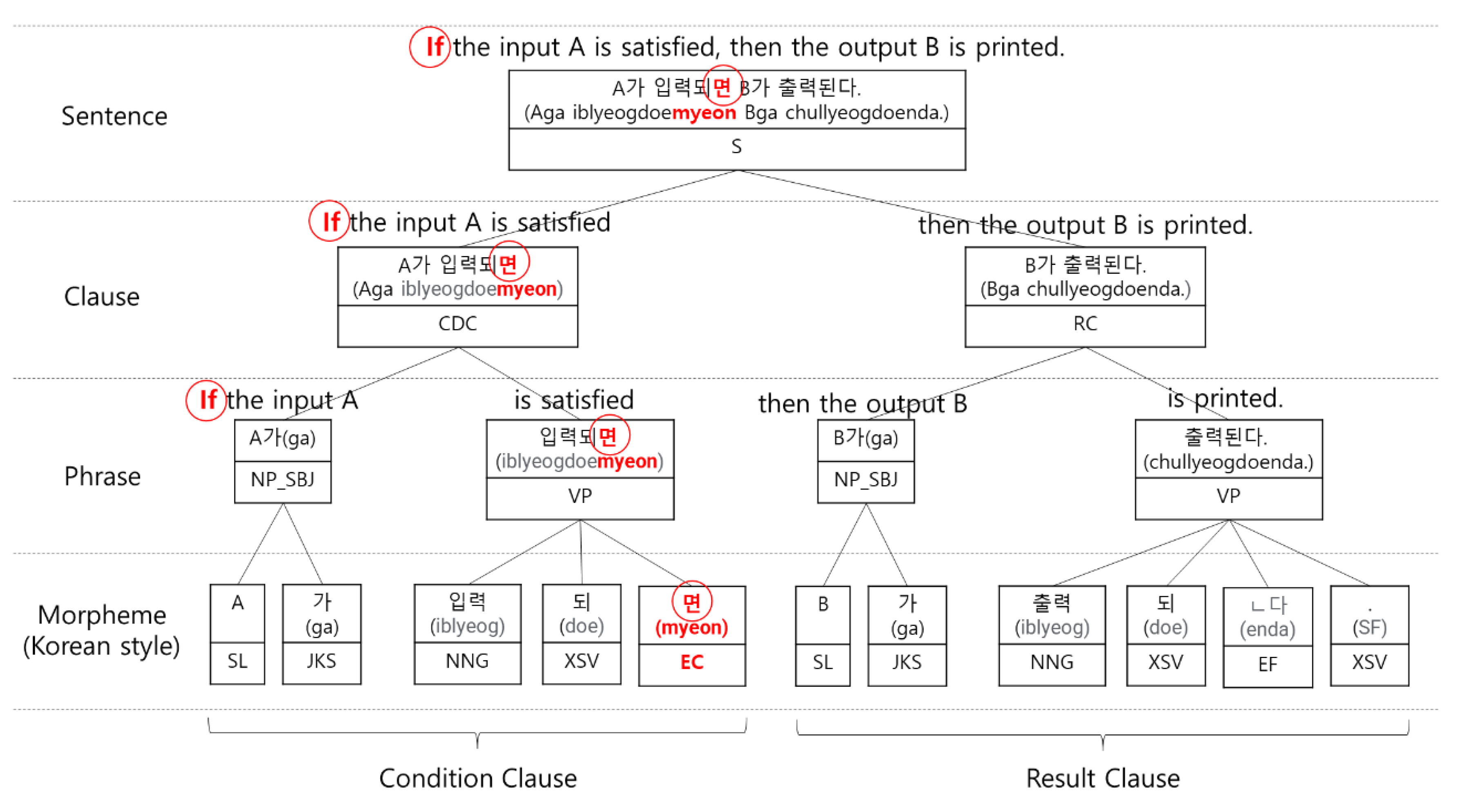
We use the identification method to identify condition clauses in natural language sentences as shown in
Figure 4.
Figure 4 consists of two clauses in the sentence. In Korean, the clauses are separated with a Connective Ending (EC). The EC as an original Korean morpheme is added at the end of Clause. The EC has diverse forms of simple and complex types.
Table 2 and
Table 3 show the types of EC for condition clauses. The Simple type means the simple EC type with a conditional meaning. The Complex type means combinations of some simple types. An Opened condition mentions the conditions of uncertain facts. A Closed condition means the conditions of certain facts. A Positive condition means the condition of true content. A Negative condition means the condition of false content. The Negative condition is expressed as a NOT relationship in the Cause-Effect Graph. As a result, as in
Table 2 and
Table 3, the clauses with the Connective Ending (EC) are Condition clauses, and the following clause of the condition clause is likely to be the result clause.
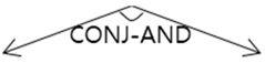
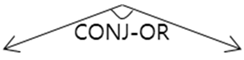
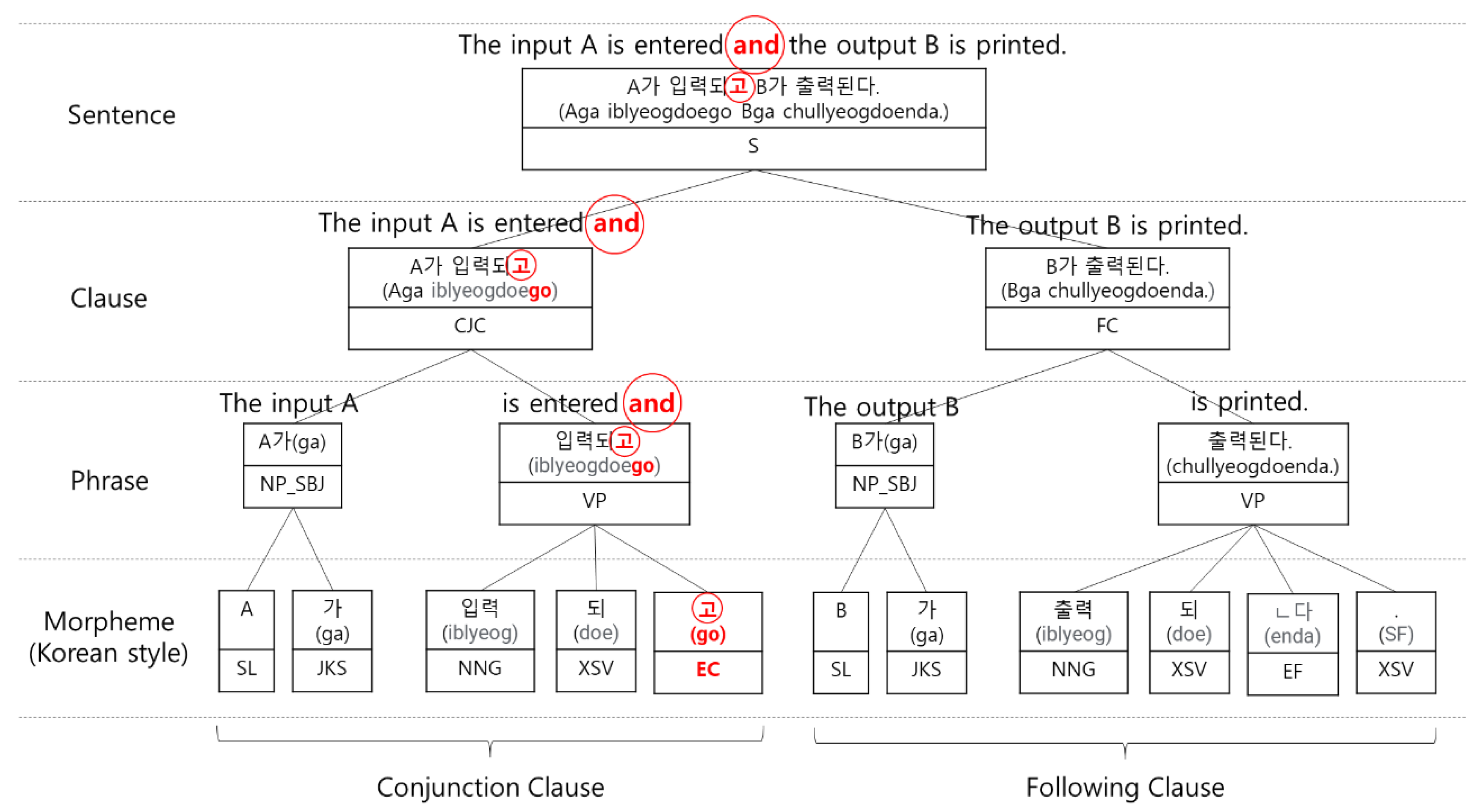
3.1.2. Identify the Conjunction-AND, Conjunction-OR Relationship
The identification method of conjunction clauses in natural language sentences is shown in
Figure 5. The sentence consists of two clauses.
Table 4 describes the types of Connective Endings for the Conjunction clause. The clauses that contain the Connective Ending (EC) of
Table 4 are Conjunction clauses. The next clause of the conjunction clause is the following clause.
Additionally, we identify “AND” and “OR” through the connective ending (EC) for the conjunction clause.
Table 5 shows the identification process. As a result, the conjunction clause and the following clause of Causality Relationship, Sequential relationship, Parallel relationship, Time relationship, Cause and Reason Relationship, Purpose and Intention Relations, and Conversion Relationship have an “AND” relationship. The conjunction clause and the following clause of Contrast Relationship, Selection Relationship, and Concession Relationship have an “OR” relationship.
3.1.3. Corpus Normalization
We use corpus normalization [
9,
10,
11] to automatically convert a sentence with a passive meaning into a sentence with an active substance. These include 1) changing the passive sentence to the active sentence and 2) changing the causative sentence to the active sentence. It is challenging to analyze the meaning of informal sentences. In the case of Korean, it is difficult to identify the subject and object in the passive sentences. That is why we convert passive sentences into active sentences. In other words, if the sentence contains an ambiguous subject and object, we can recognize the clear subject and object through corpus normalization. This method changes the form or position of a case marker in the sentence. The case marker is only one of the morphemes in the Korean language. For example, the case marker ‘가(ga)’ is also only the Korean morpheme. The ’A가(ga)’ means that a subject ‘A’ and a case marker ‘가(ga).’ Therefore, we represent the case marker ‘가(ga)’ after a noun ‘A’ in
Figure 5. The subject word in Korean Sentence admits any front position of a sentence, unlike English sentences, such as ‘Subject = word + subject case marker’ and ‘Object = word + object case marker.’ A subject and an object are determined according to the type of case marker. As a result, the form and position of the case marker are changed, then the subject can be changed to the object. An Underlined is a case marker.
Table 6 shows the example case.
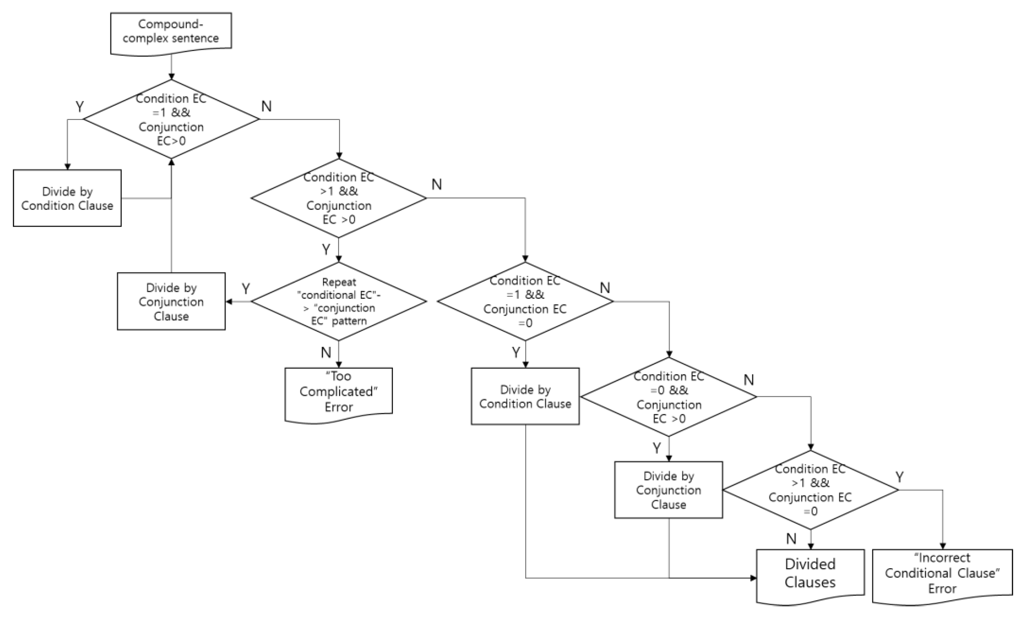
3.1.4. Identify the Order of Each Different Clause
We propose a clause order recognition method for identifying each clause’s priority of connective endings (ECs) in a sequential or composited sentence. In
Figure 6, we show our clause order algorithm for determining the priority of each connective ending (EC) of clauses in a sentence as follows: In the first step, identify all kinds of ECs and the number of ECs in the sentence, in the second step, classify condition clause/result clause or conjunction clause/result clause. Until not including any EC in the sentence, the whole sentence crumbles into fractions, that is, morphemes of phases of clauses of one sentence.
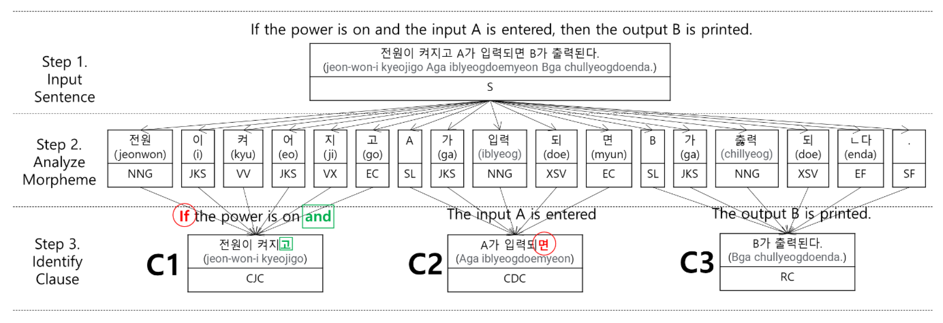
In
Figure 7, we identify three clauses (C1, C2, C3) with the connective ending (EC) of the morphemes after identifying the morphemes in the sentence. When we adopt the clause order algorithm with three clauses C1, C2, and C3 in
Figure 7, we can locate the ‘AND’ relationship between C1 and C2 and identify the ‘IF-Then’ relationship between C3 and ‘C1∩C2’.
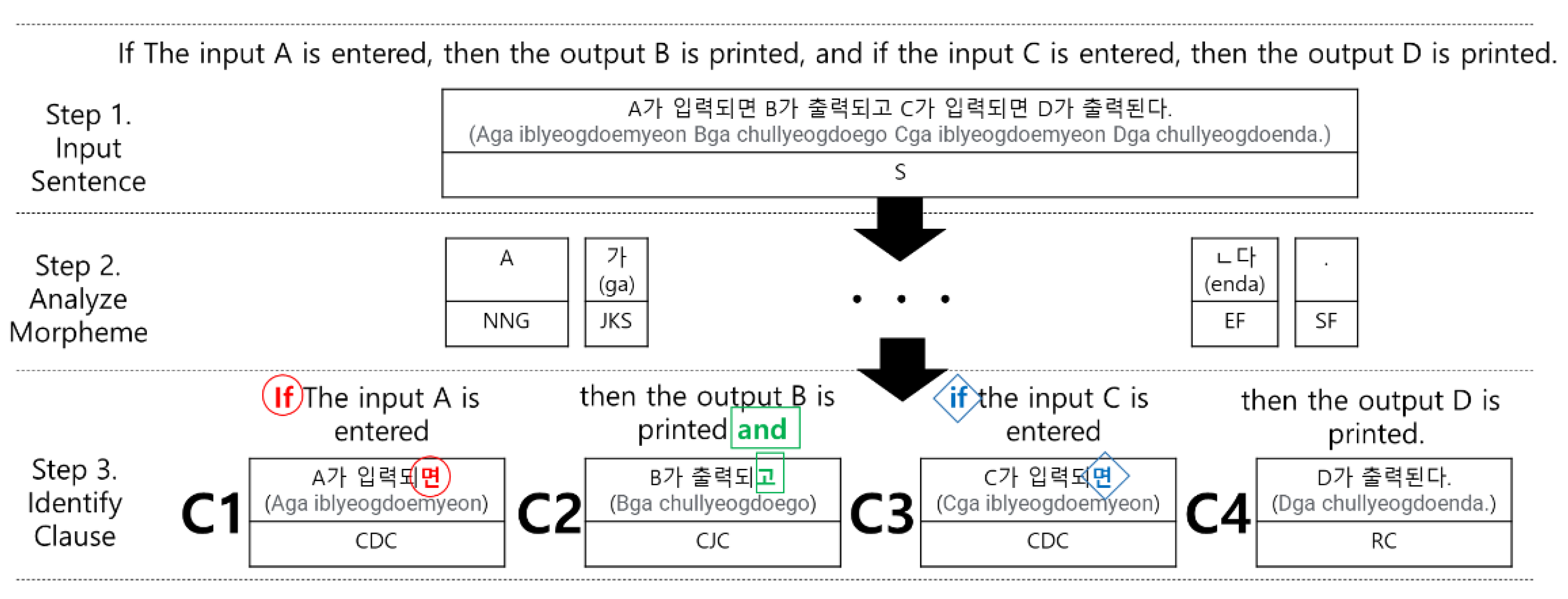
Figure 8 shows four clauses (C1, C2, C3, and C4) in a sentence. By applying the clause order algorithm with four clauses C1, C2, C3, and C4, in
Figure 8, we can identify the ‘IF-Then’ relationship between C1 and C2 and identify the ‘IF-Then’ relationship between C3 and C4. Finally, place the ‘AND’ relationship between them.
We mention the clauses of natural language sentences combined in various ways, for example, sentence complexity with diverse clause combinations. However, we consider some limited formulas of clause identification patterns within
Table 7.
3.2. Step 2. Generate C3Tree Model
We define C3Tree Model (like a tree structure) to convert a simplified sentence into a complex sentence.
3.2.1. Do Simplification Method
First, we store ‘the original complex sentence’ into the top node root of this Model. Second. We also save the simplified sentence into the bottom nodes of the tree model. Third, until not is any condition and conjunction clause in the sentence, we repeatedly separate into condition clause and result clause if having any EC in the condition clause of a sentence or split into conjunction clause and the following clause if including any EC in the conjunction clause of a sentence.
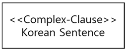
3.2.2. Define Notations of the C3Tree Model
The C3Tree Model consists of nodes and links for visualizing the sentence simplification. That is, we divide a long and complex sentence into some short sentences.
Table 8 shows nodes and links of the C3Tree Model.
The C3Tree Model is expressed by XMI code.
Table 9 is an example of the C3Tree Model XMI code.
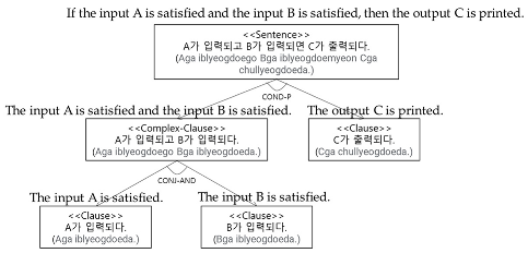
3.3. Transform C3Tree Model to Cause-Effect Graph
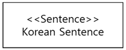
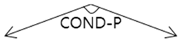
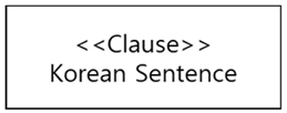
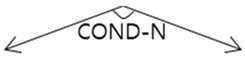
In this section, we transform the notations of C3Tree Model notation into the notation of the Cause-Effect Graph. Therefore, a <<Clause>> node of the C3Tree Model is transformed into a <<Node>> in the Cause-Effect Graph. In
Table 10, we show the transformation relationship between C3Tree Model and Cause-Effect Graph.
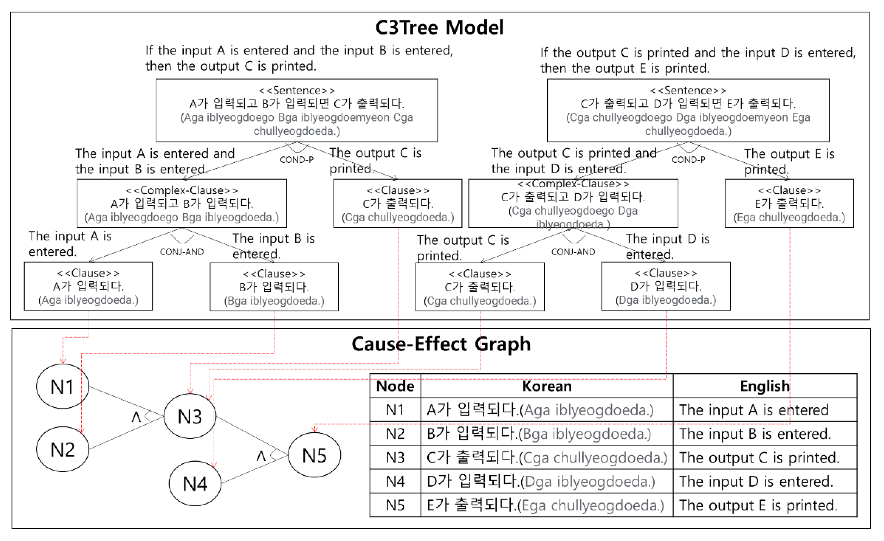
Figure 9 is an example of the transformation process. First, five <<Clause>> nodes at the bottom level of C3TREE are transformed to N1~N5 of a cause-effect graph. The left node of COND-J is transformed to the Cause node. The right node of COND-J is transformed as the Effect node. CONJ-AND is transformed to AND. “The output C is printed” node of the left tree and “The output C is printed” node of the right tree has the same sentence. Therefore, the “The output C is printed” node of the left tree and “The output C is printed” node of the right tree are integrated into N3.
The Cause-Effect Graph is expressed in XMI code.
Table 11 is the XMI code for Cause-Effect Graph in
Figure 9.
4. Automatic Generation Mechanism
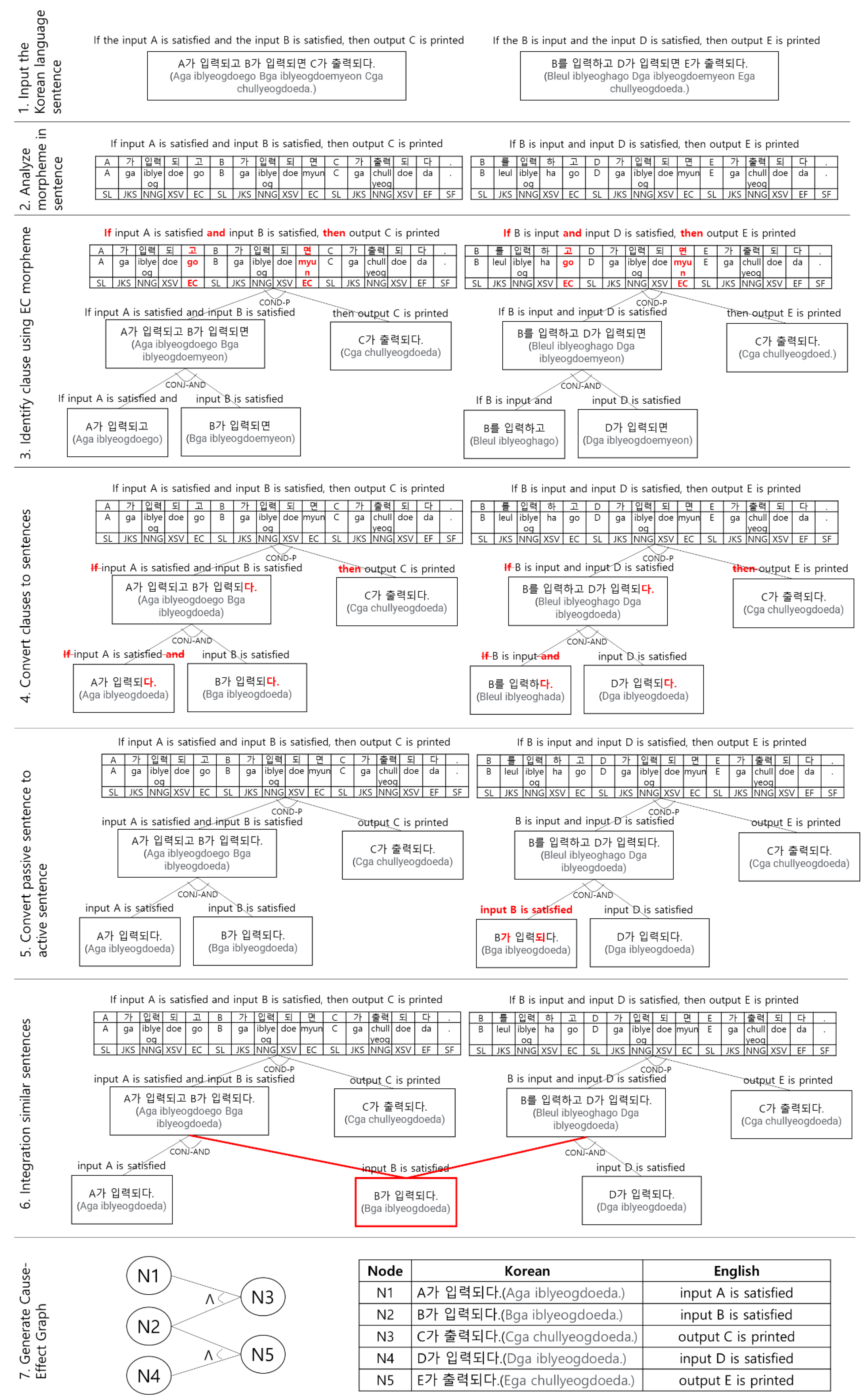
We suggest the automatic generation mechanism mentioned in chapter 3. That is, we describe the procedure of the automatic generation mechanism with informal requirements sentences and then generate a Cause-Effect Graph as follows: (1) Input the Korean language sentence, (2) Analyze morpheme in a sentence, (3) Identify cause using EC morpheme, (4) Convert clauses to sentences, (5) Convert passive sentence to active sentence, (6) Integration similar sentences, (7) Generate Cause-Effect Graph.
Figure 10 shows the detailed procedure of the generation process.
5. A Case Study
We explain our mechanism with real requirements of ‘A guidance for completing DPS for a Missile system [
12].
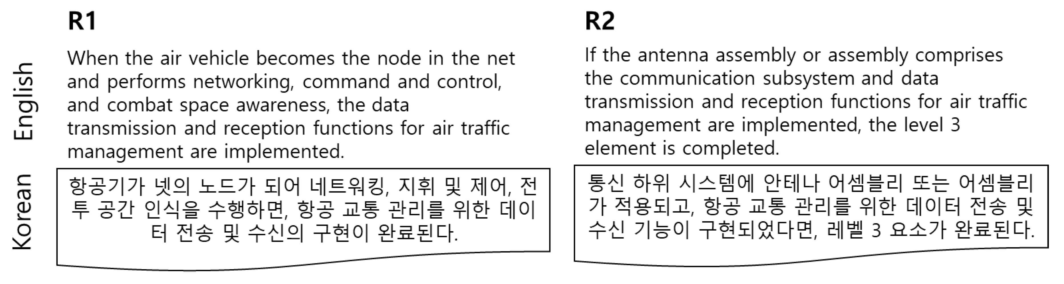
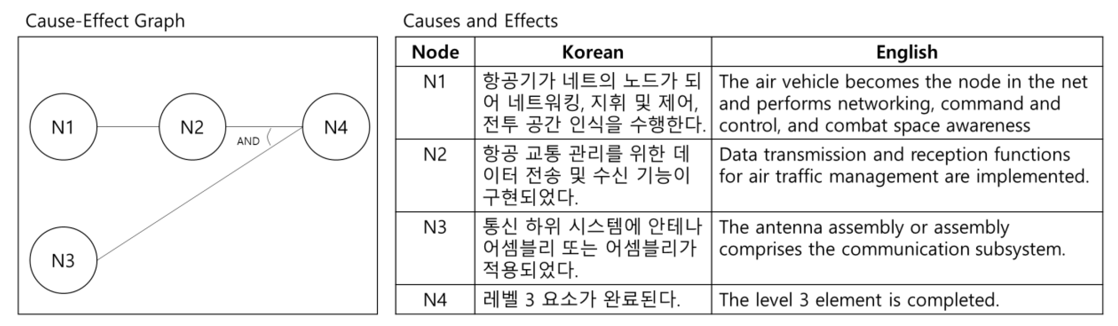
Figure 11 is part of the requirement specifications (R1.1.7 communications) in the missile system.
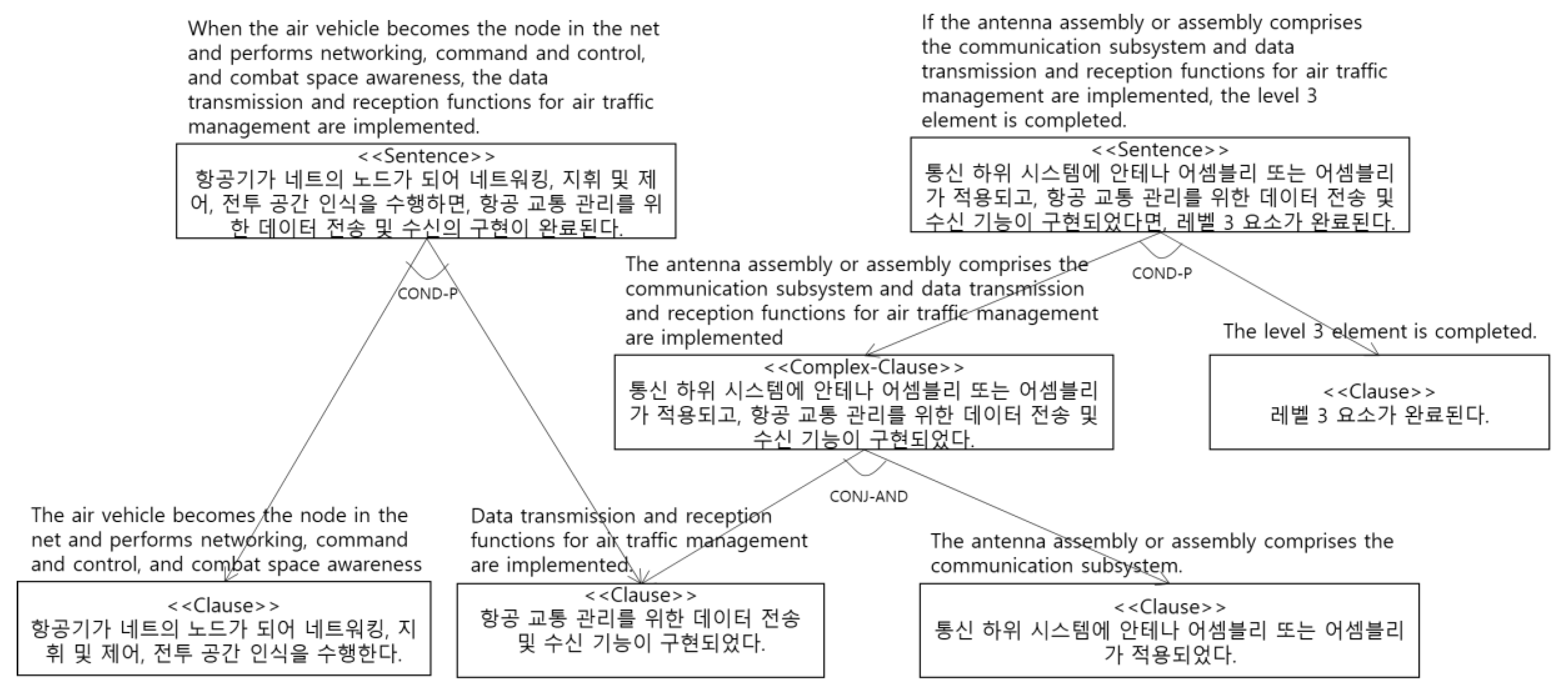
Figure 12 is the C3Tree Model generated from the requirement specification. Four <<Clause>> were generated.
Figure 13 is the Cause-Effect Graph generated from the C3Tree Model. Four <<Clause>> are changed to nodes.
6. Conclusions and Future Research
Our software industries ask us to automatically generate test cases with only informal Korean requirement documents in the Korea academy. Until now, none consider test case generation with informal Korean requirements. We focus on automatically generating test cases from requirements. As our first step, we propose a mechanism for automatically transforming requirements into the Cause-Effect Graphs as an intermediate process for generating test cases from informal requirement specifications written in the Korean language. To do this, we define our C3Tree structure for converting complex and lengthy sentences to simplified and short sentences, which are generated by applying a formal sentence analysis method with requirements and provided traceability of intermediate changing steps between the original sentence and a Cause-Effect Graph. As a case study, we apply the proposed mechanism with actual requirements of the Defined Pricing Structure (DPS) for a Missile system.
In future work, we should develop our tool for dealing with a vast requirement, which effectively and automatically transforms test cases via the Cause-Effect Model from informal requirement sentences.
Author Contributions
W.S.J. and R.Y.C.K. designed the present study, reviewed the literature, and drafted the manuscript; W.S.J. and R.Y.C.K. performed the verification of the model generation process; W.S.J. and R.Y.C.K. critically revised the manuscript. All authors have read and agreed to the published version of the manuscript.
Funding
This work was supported by the National Research Foundation (NRF), Korea, under project BK21 FOUR (F21YY8102068), and also by Basic Science Research Program through the National Research Foundation of Korea (NRF) funded by the Ministry of Education (2021R1I1A305040711).
Institutional Review Board Statement
Not applicable.
Informed Consent Statement
Not applicable.
Conflicts of Interest
The authors have no conflict of interest.
References
- Kwon, O.S.; Hong, S.N. Effective iterative testing based on log. In Proceedings of the Korea Society of Management Information Systems Fall Conference, Seoul, Korea, 13 November 2009; pp. 685–690. [Google Scholar]
- Shepperd, M.; Ince, D. Derivation and Validation of Software Metrics; Oxford Science Publications: Oxford, UK, 1993. [Google Scholar]
- Mogyorodi, G.E. Requirements-Based Testing-Cause-Effect Graphing; In Software Testing Services: ON, Canada, 2005. [Google Scholar]
- Son, H.S.; Park, Y.B.; Kim, R.Y.C. Test case Generation from Cause-Effect Graph based on Model Transformation. In Proceedings of the 2014 International Conference on Information Science & Applications (ICISA), Seoul, Korea, 6–9 May 2014; pp. 591–593. [Google Scholar]
- Myers, G.L. The Art of Software Testing; John Wiley & Sons, Inc.: Hoboken, NJ, USA, 1979. [Google Scholar]
- Bekiroglu, B. A Cause-Effect Graph Software Testing Tool. Eur. J. Comput. Sci. Inf. Technol. 2017, 5, 11–24. [Google Scholar]
- Woo, S.; Son, H.; Kim, W.; Kim, J.; Kim, R.Y. A Study Testcase Extraction based M&S for Pre-Testing. Korea Conf. Softw. Eng. 2012, 14, 181–183. [Google Scholar]
- Ha, J.M. A Contrastive Study on Korean Conditional Connective Ending and Chinese Conditional Conjunction Expression; Kyunghee University: Seoul, Korea, 2007. [Google Scholar]
- Cho, J.M.; Cho, Y.H.; Kim, G.C. A Corpus Formalization for Extracting the Syntactic Relations. In Proceedings of the 8th Annual Conference on Human & Cognitive Language Technology, Daejeon, Korea, 11 October 1996; pp. 207–215. [Google Scholar]
- Cho, J.M.; Kim, G.C. A Corpus Formalization for Extracting the Syntactic Relations. Korean Soc. Cogn. Sci. 1996, 7, 39–56. [Google Scholar]
- Kim, K.A. Comparative Study on Conjoined Sentence between Modern Mongolian and Korean. Korean Assoc. Mong. Stud. 2009, 27, 151–186. [Google Scholar]
- Guidance for Completing DPS for a Missile System. Available online: https://www.gov.uk/government/uploads/system/uploads/attachment_data/file/437322/DPS_principles_guidance.PDF (accessed on 1 November 2021).
Figure 1.
Connection Types between the identified Nodes for the Cause-Effect Graph.
Figure 1.
Connection Types between the identified Nodes for the Cause-Effect Graph.
Figure 2.
The Model transformations [
4].
Figure 2.
The Model transformations [
4].
Figure 3.
The Process of Cause-Effect Graph Generation from Informal Requirement Spec.
Figure 3.
The Process of Cause-Effect Graph Generation from Informal Requirement Spec.
Figure 4.
Identification of conditional clauses.
Figure 4.
Identification of conditional clauses.
Figure 5.
Identification of conjunction clauses.
Figure 5.
Identification of conjunction clauses.
Figure 6.
The clause order algorithm for identifying the priority of each connective ending (EC) of clauses in a sentence.
Figure 6.
The clause order algorithm for identifying the priority of each connective ending (EC) of clauses in a sentence.
Figure 7.
One example of identifying the priority of clauses in a simple sentence.
Figure 7.
One example of identifying the priority of clauses in a simple sentence.
Figure 8.
One example of identifying the priority of clauses in a composite sentence.
Figure 8.
One example of identifying the priority of clauses in a composite sentence.
Figure 9.
The transformation process of Cause-Effect Graph from C3Tree Model.
Figure 9.
The transformation process of Cause-Effect Graph from C3Tree Model.
Figure 10.
Our automatic generation mechanism of the Korean Requirements Analyzer for Cause-Effect Graph.
Figure 10.
Our automatic generation mechanism of the Korean Requirements Analyzer for Cause-Effect Graph.
Figure 11.
Requirement specifications in the missile system.
Figure 11.
Requirement specifications in the missile system.
Figure 12.
C3Tree Model generated from Requirement specifications.
Figure 12.
C3Tree Model generated from Requirement specifications.
Figure 13.
Cause-Effect Graph generated from C3Tree Model.
Figure 13.
Cause-Effect Graph generated from C3Tree Model.
Table 1.
Parts of POS tags in the Korean language.
Table 1.
Parts of POS tags in the Korean language.
| Tag | Description | Tag | Description | Tag | Description |
|---|
| S | Sentence | VP | Verb phrase | EF | Final ending |
| CDC | Condition Clause | SL | Foreign language | SF | Terminal punctuation |
| RC | Result Clause | JKS | Subjective case marker | VV | Verb |
| CJC | Conjunction Clause | NNG | General Noun | VX | Auxiliary verb |
| FC | Following Clause | XSV | Verb derivational suffix | - | - |
| NP_SBJ | Subjective noun phrase | EC | Connective ending | - | - |
Table 2.
Part of Connective ending (EC) types [
8] in the Korean language.
Table 2.
Part of Connective ending (EC) types [
8] in the Korean language.
| Connective Ending (EC) Type | EC Forms (Korean) | English Description |
|---|
| Simple type | -면(Myun), -거든(Geodeun), -어야(Uya) | Simple IF statements |
| Complex type | -다면(Damyeon), -은들(Eundeul), -다가(Daga), -든지(Deunji), -려면(Lyeomyeon), -거드면(Geodeumyeon), -거들랑(Geodeullang), -대서야(Daeseoya), -고야(Goya), … | Nested IF statements |
Table 3.
Part of Condition types [
8] in the Korean language.
Table 3.
Part of Condition types [
8] in the Korean language.
| Condition Type | Subtype | EC Forms (Korean) | English Description |
|---|
| Opened condition | - | -면(Myun), -거든(Geodeun), … | It means conditions of uncertain facts. |
| Closed condition | Positive condition | -아(A)/어(Uh)/여야(Uya), … | It means conditions of certain facts.
The Result is positive (true). |
| Negative condition | -던들(Deondeul), … | It means conditions of certain facts.
The result is negative (false). |
Table 4.
Parts of Combination Types between Conjunctions.
Table 4.
Parts of Combination Types between Conjunctions.
| Conjunction Type | EC Forms [9,10,11] (Korean) | English Description |
|---|
| Causality Relationship | ‘-느라고(Nerago),’ Etc. | If B for A, then C.
(A = true, B = true, C = true) |
| Sequential relationship | ‘-고(Go)(서(Seo)),’ Etc. | If B after A, then C.
(A = true, B = true, C = true) |
| Parallel relationship | ‘-고(Go),’ ‘-(으(Eu))며(Myeo),’ ‘-(으(Eu)면서(Myeonseo),’ Etc. | If A and B are at the same time, then C.
(A = true, B = true, C = true) |
| Contrast Relationship | ‘-(으(Eu))나(Na),’ ‘-지만(Jiman),’ Etc. | If A and B, then C.
(A = false, B = true, C = true) |
Table 5.
Parts of Logical Expression of Conjunction.
Table 5.
Parts of Logical Expression of Conjunction.
| Conjunction Type | Mathematical
Expression | A Logical Combination of A and B for C = True |
|---|
Causality
Relationship | B:A- > C | AND |
Sequential
relationship | A:B- > C | AND |
| Parallel relationship | A||B- > C | AND |
Contrast
Relationship | ¬A:B- > C | OR |
Table 6.
One Example of Converting Passive Sentence to Active Sentence.
Table 6.
One Example of Converting Passive Sentence to Active Sentence.
| Passive Sentence | Active Sentence |
|---|
| Korean | English | Korean | English |
|---|
| 그들에 의해 협상이 깨어지다. (geudeul-e uihae hyeobsang-i kkaeeojida.) | Negotiations are broken by them. | 그들이 협상을 깨다. (geudeul-i hyeobsang-eul kkaeda.) | They break
negotiations. |
Table 7.
Types of identifiable clause patterns.
Table 7.
Types of identifiable clause patterns.
| Pattern | Formula | Identification Clause | Pattern | Formula | Identification Clause |
|---|
| 1 | | CF identification | 4 | | CF identification after CR identification |
| 2 | | CR identification | 5 | | CF identification after CR identification |
| 3 | | CR identification after CF identification | 6 | | CR identification after CF identification |
Table 8.
C3Tree Notation.
Table 9.
XMI Code of C3Tree Model Example.
Table 9.
XMI Code of C3Tree Model Example.
| C3Tree Model | ![Applsci 11 11775 i008]() |
XMI Code
(Korean) | <node ctid=“1” type=“sentence” string=“A가 입력되고 B가 출력되면 C가 출력되다.”/>
<node ctid=“2” type=“cclause” string=“A가 입력되고 B가 입력되다.”/>
<node ctid=“3” type=“clause” string=“C가 출력되다.”/>
<node ctid=“4” type=“clause” string=“A가 입력되다.”/>
<node ctid=“5” type=“clause” string=“B가 입력되다.”/>
<link type=“condp” parent=“1” left=“2” right=“3”/>
<link type=“conjand” parent=“2” left=“4” right=“5”/> | XMI Code
(English) | <node ctid=“1” type=“sentence” string=“If the input A is satisfied and the input B is satisfied, then the output C is printed.”/>
<node ctid=“2” type=“clause” string=“The input A is satisfied and the input B is satisfied.”/>
<node ctid=“3” type=“clause” string=“The output C is printed.”/>
<node ctid=“4” type=“clause” string=“The input A is satisfied.”/>
<node ctid=“5” type=“clause” string=“The input B is satisfied.”/>
<link type=“condp” parent=“1” left=“2” right=“3”/>
<link type=“conjand” parent=“2” left=“4” right=“5”/> |
Table 10.
Relationship between C3Tree Model Notations and Cause-Effect Graph Notations.
Table 10.
Relationship between C3Tree Model Notations and Cause-Effect Graph Notations.
| Case | C3Tree Model Notation | Cause-Effect Graph Notation |
|---|
| 1 | Clause | Node |
| 2 | CONJ-AND | AND |
| 3 | CONJ-OR | OR |
| 4 | The left child node of COND-P(COND-N) | Cause |
| 5 | The right child node of COND-P(COND-N) | Effect |
| 6 | COND-P | Identity |
| 7 | COND-N | NOT |
Table 11.
XMI Code of Cause-Effect Graph.
Table 11.
XMI Code of Cause-Effect Graph.
| XMI Code (Korean) | XMI Code (English) |
|---|
<node ctid=”3;” ceid=”1” string=”A가 입력되다.”/>
<node ctid=”5;” ceid=”2” string=”B가 입력되다.”/>
<node ctid=”4;7;” ceid=”3” string=”C가 출력되다.”/>
<node ctid=”8;” ceid=”4” string=”D가 입력되다.”/>
<node ctid=”6;” ceid=”5” string=”E가 출력되다.”/>
<link type=”and” cause=”1;2;” effect=”3”/>
<link type=”and” cause=”3;4;” effect=”5”/> | <node ctid=”3;” ceid=”1” string=”The input A is entered.”/>
<node ctid=”5;” ceid=”2” string=”The input B is entered.”/>
<node ctid=”4;7;” ceid=”3” string=”The output C is printed.”/>
<node ctid=”8;” ceid=”4” string=”The input D is entered.”/>
<node ctid=”6;” ceid=”5” string=”The output E is printed.”/>
<link type=”and” cause=”1;2;” effect=”3”/>
<link type=”and” cause=”3;4;” effect=”5”/> |
| Publisher’s Note: MDPI stays neutral with regard to jurisdictional claims in published maps and institutional affiliations. |
© 2021 by the authors. Licensee MDPI, Basel, Switzerland. This article is an open access article distributed under the terms and conditions of the Creative Commons Attribution (CC BY) license (https://creativecommons.org/licenses/by/4.0/).


