
Hybrid Power System for the Range Extension of Security Robots: Specification Development Phase

Abstract
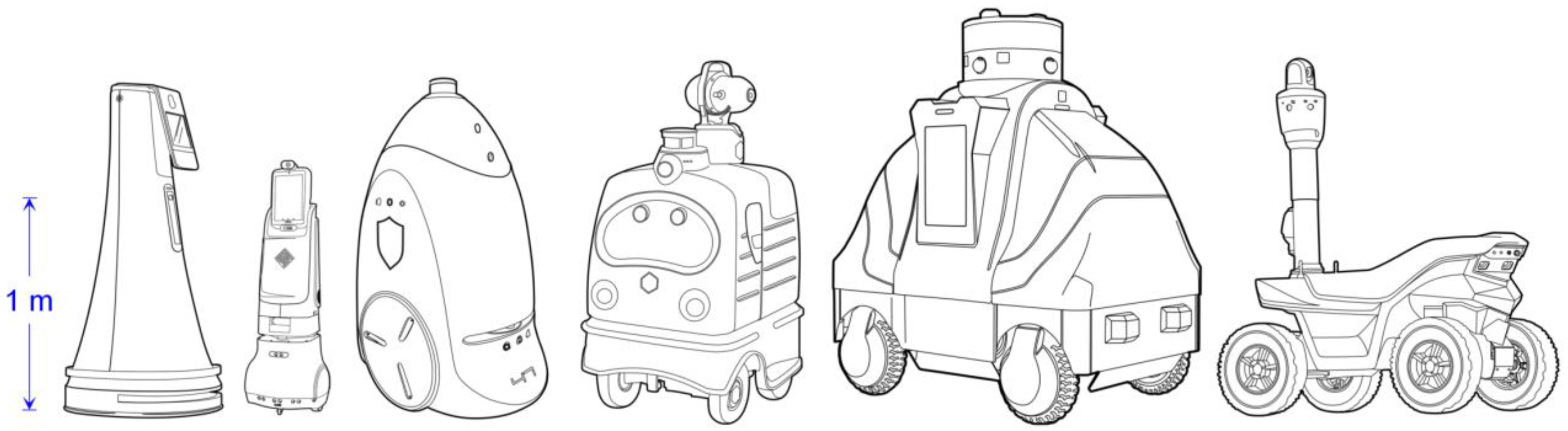
:1. Introduction
2. System Structure
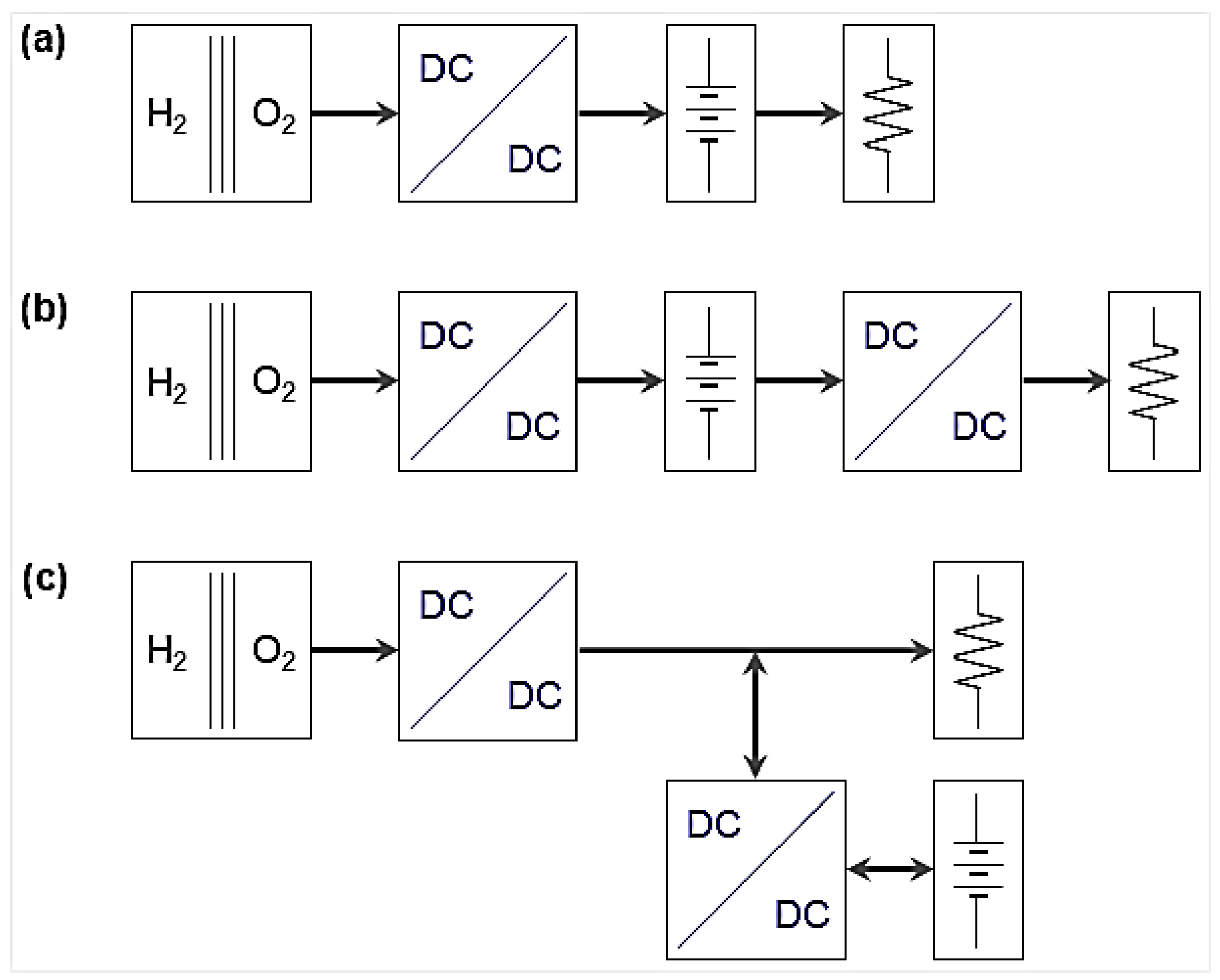
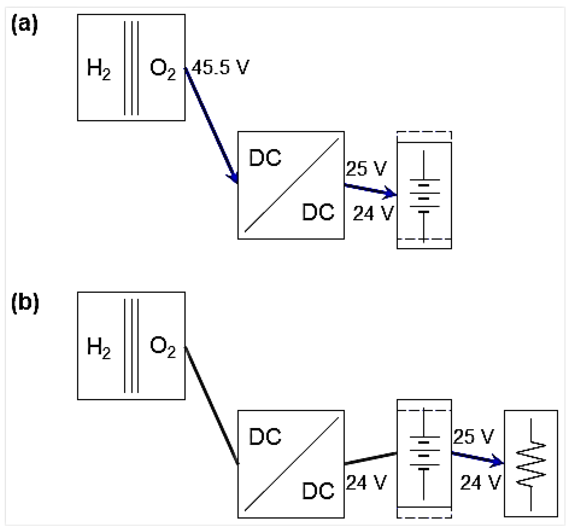
2.1. Passive Structure
2.2. Active Structure
2.3. Selected Structure
3. Component Specifications
3.1. Energy Specification
3.2. Power Specification
3.3. Selected Components
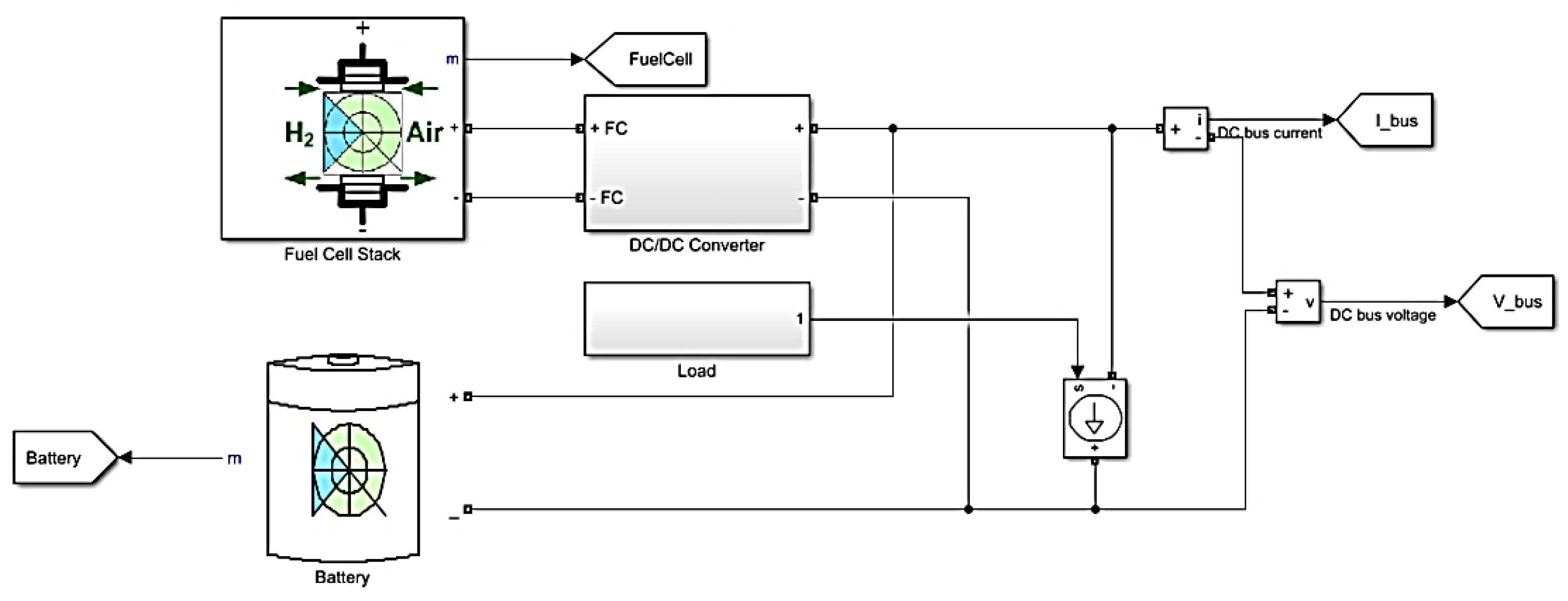
4. Simulator Development
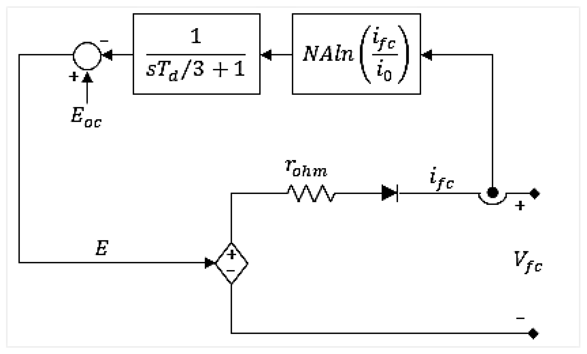
4.1. Fuel Cell Model
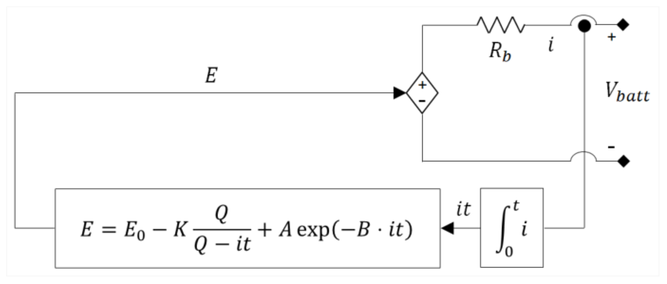
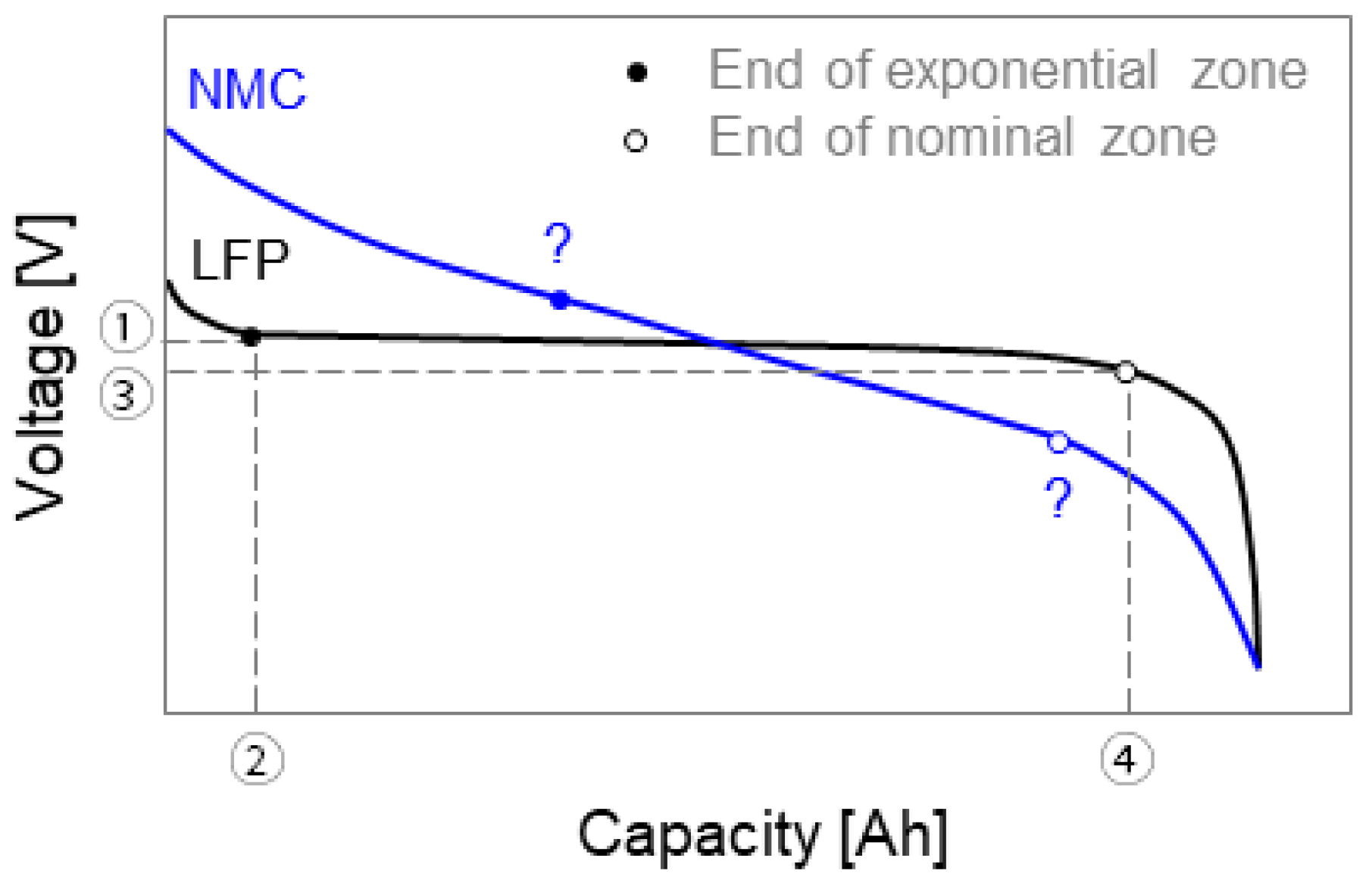
4.2. Battery Model
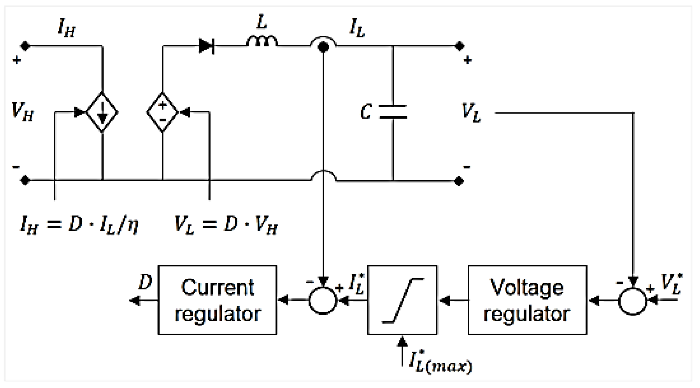
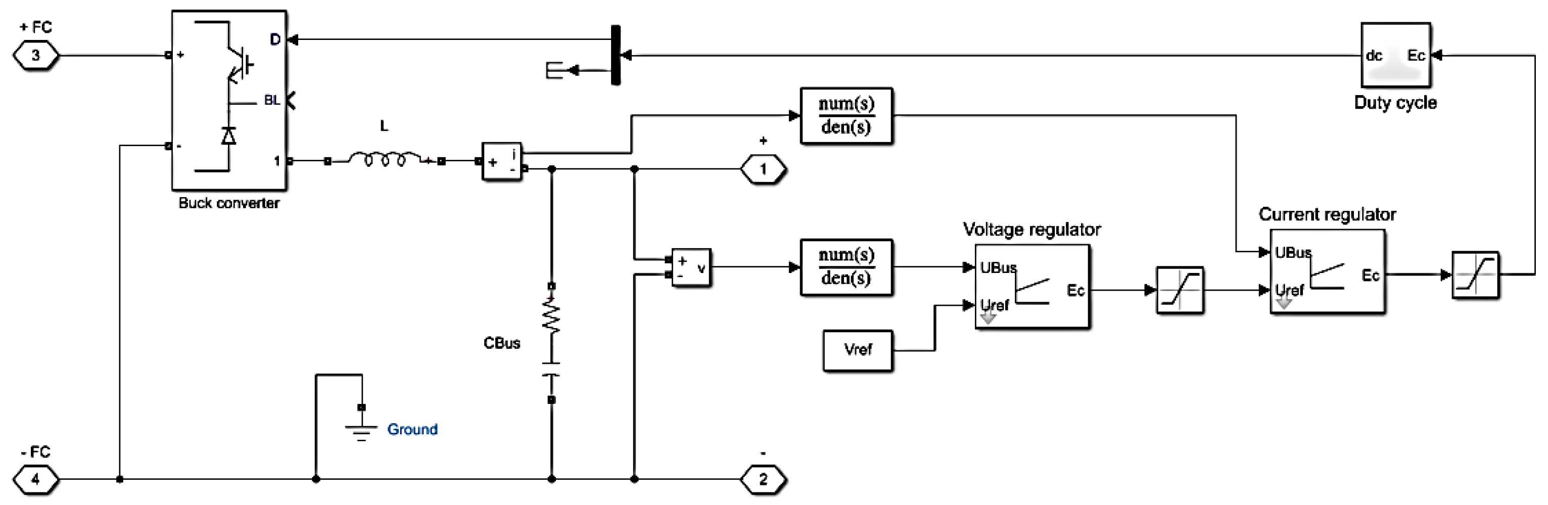
4.3. Converter Model
5. Simulation Verification
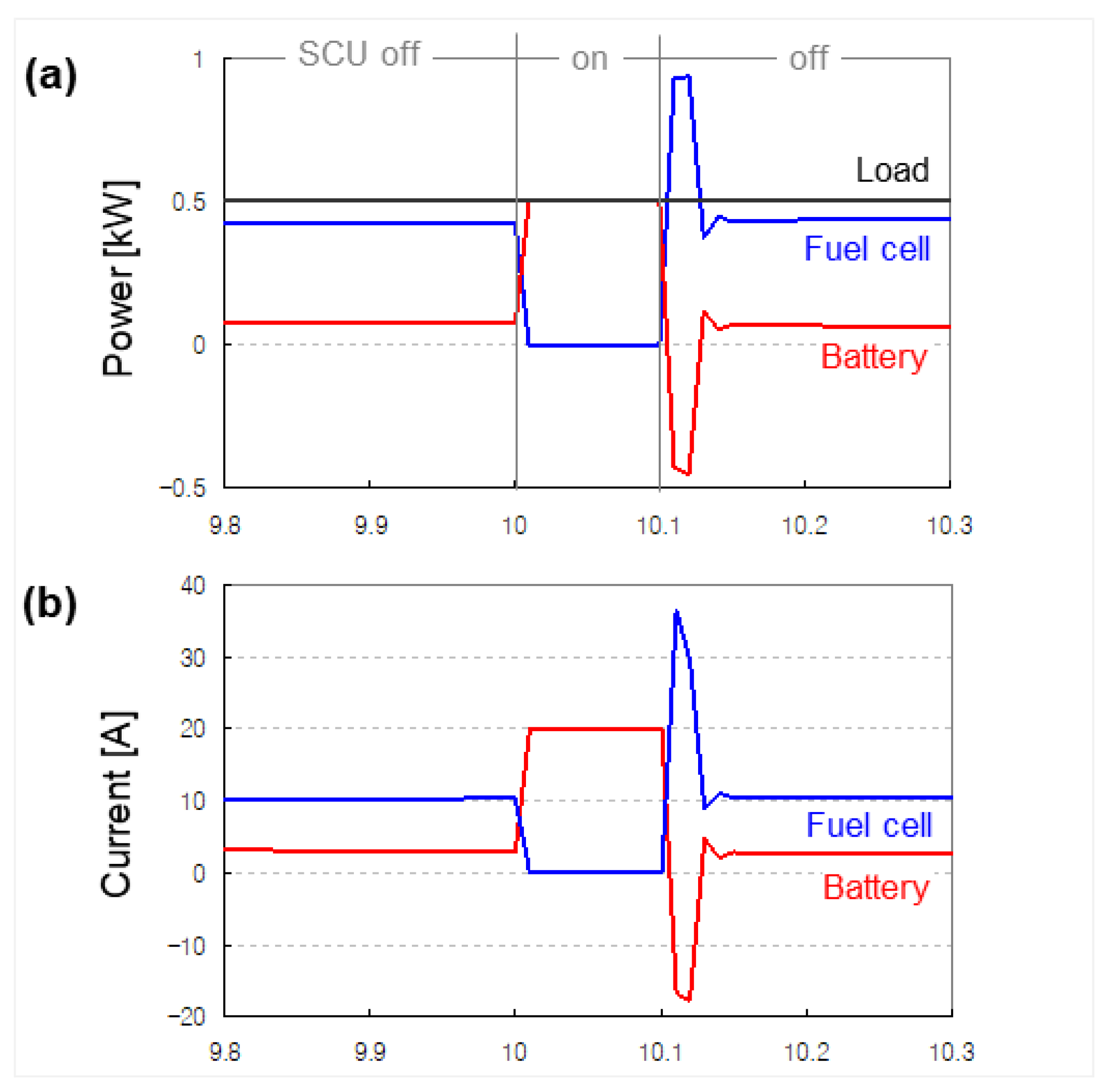
5.1. Overloading
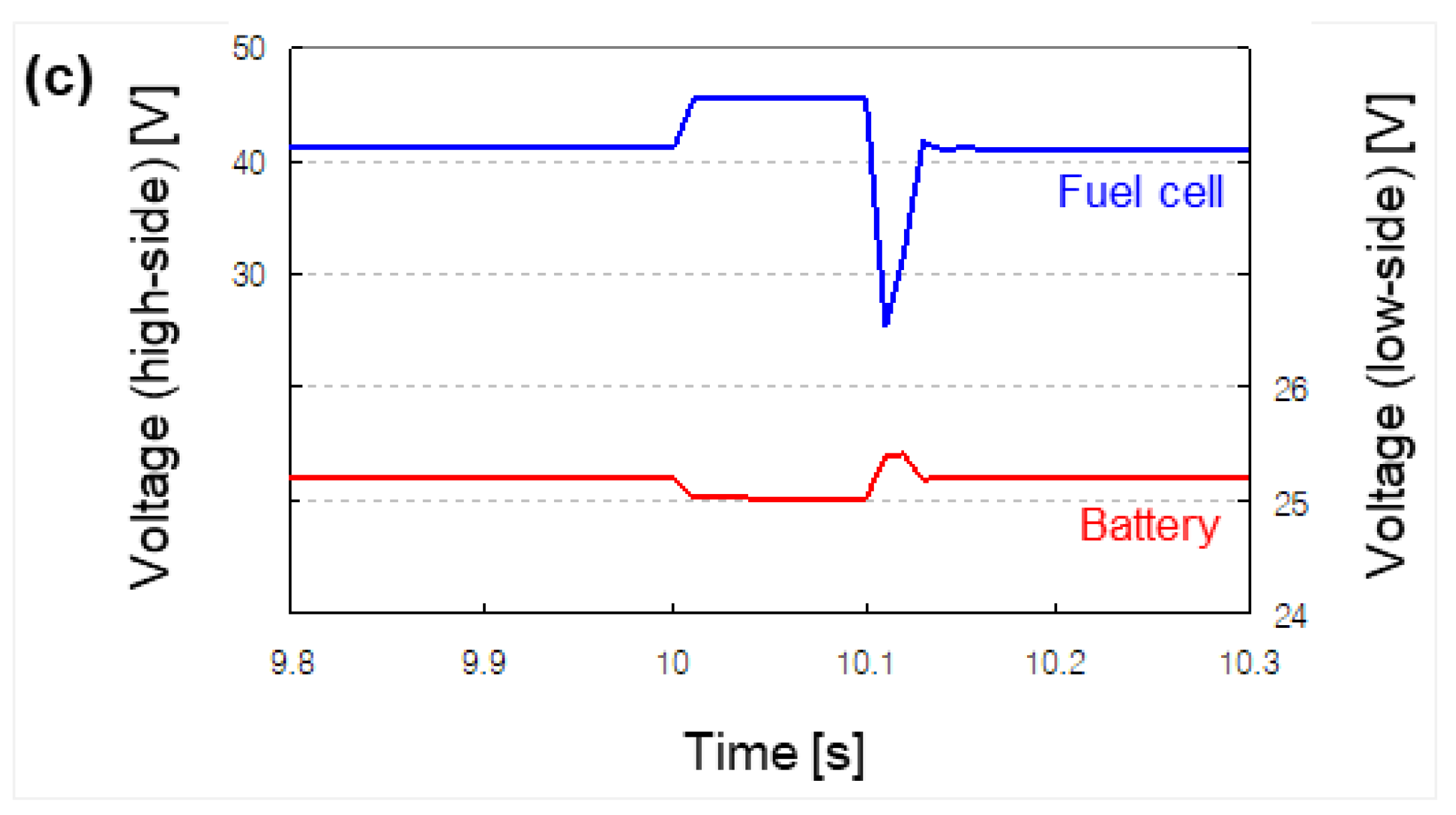
5.2. Terminal Short-Circuiting
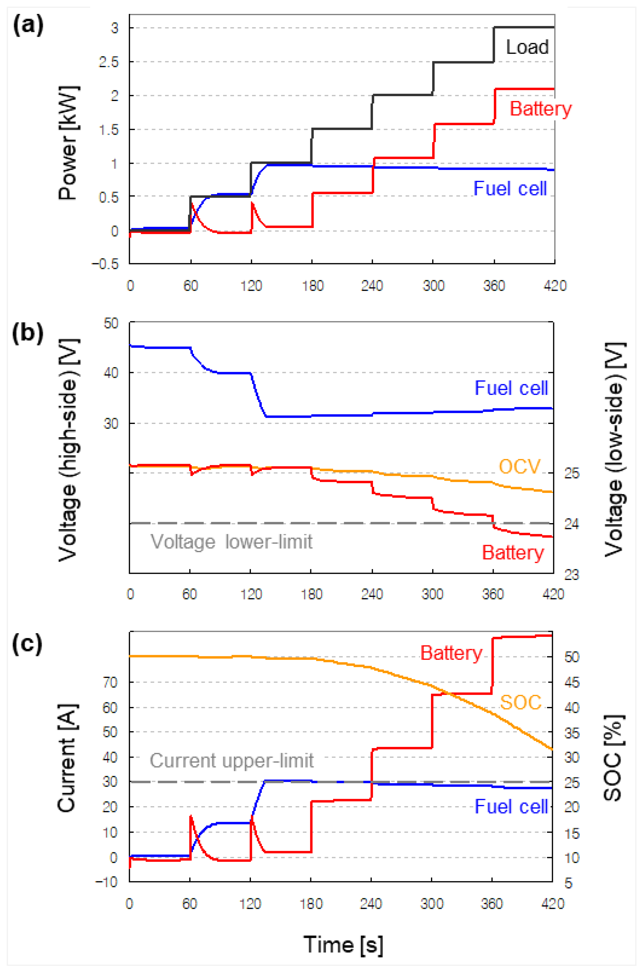
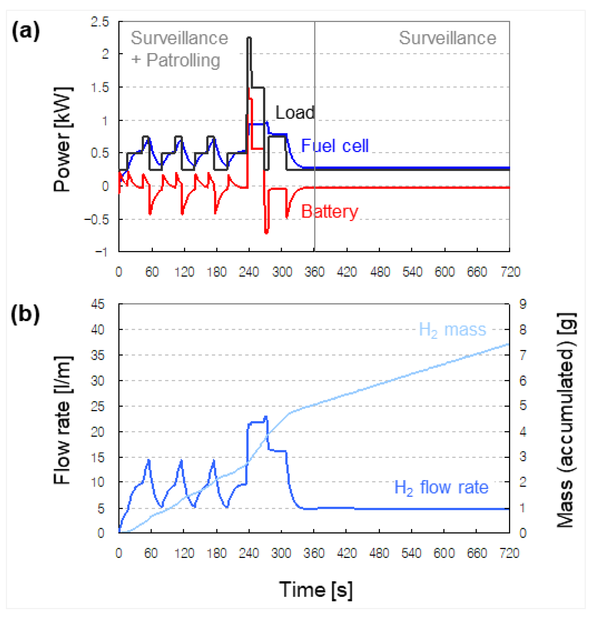
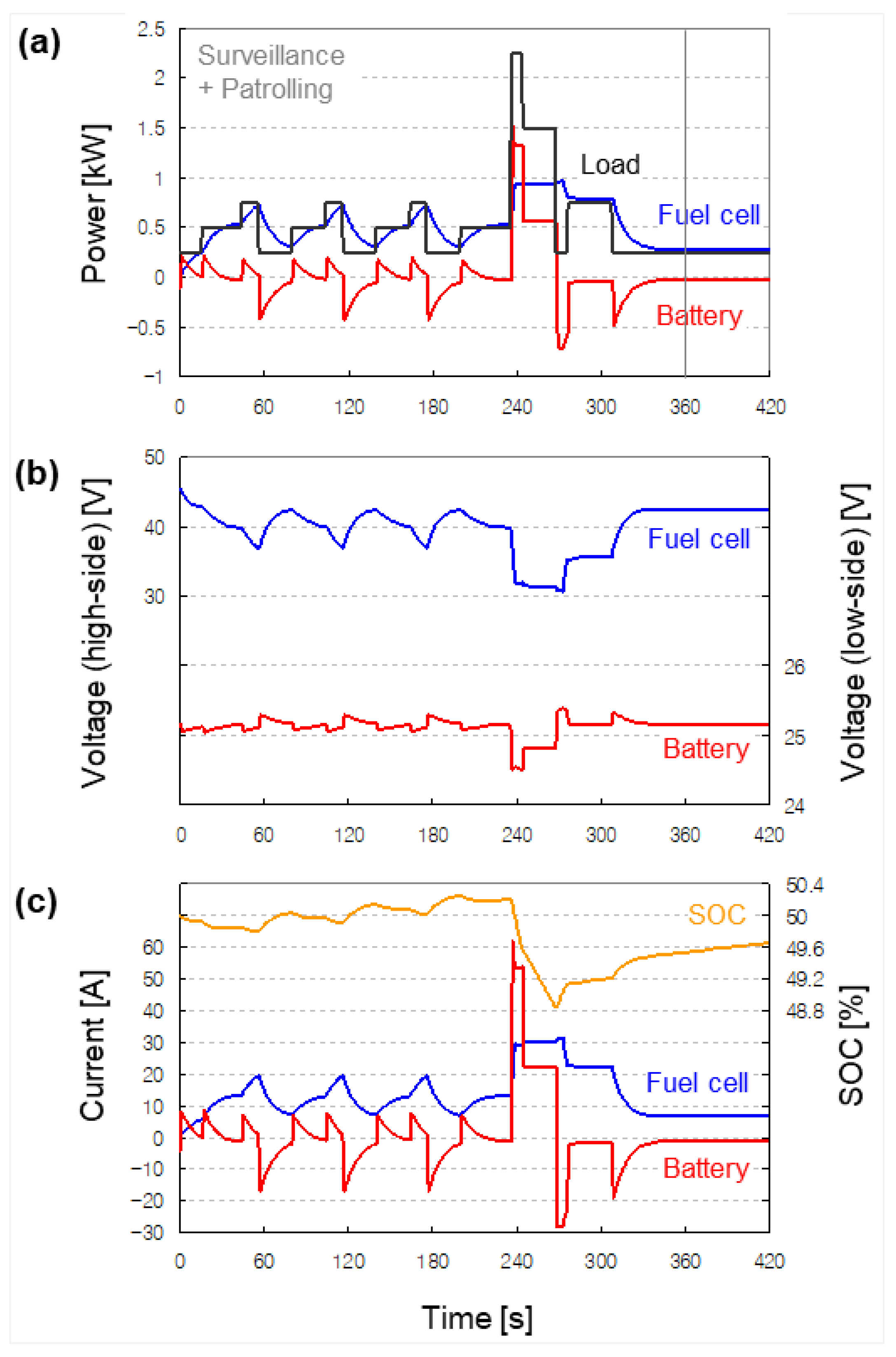
5.3. Drive Cycle
6. Conclusions
Funding
Institutional Review Board Statement
Informed Consent Statement
Data Availability Statement
Conflicts of Interest
References
- Advanced Observation & Reporting. Available online: https://www.cobaltrobotics.com/ (accessed on 15 October 2021).
- Robots: Augmenting Physical Security. Available online: https://www.cobaltrobotics.com/wp-content/uploads/2020/06/Cobalt-Robotics-Whitepaper-Robots-Augmenting-Physical-Security.pdf (accessed on 4 September 2021).
- Cobalt Robotics Introduces a (mostly) Autonomous Mobile Security Robot. Available online: https://spectrum.ieee.org/cobalt-robotics-introduces-mobile-security-robot (accessed on 1 November 2021).
- O-R2, Multipurpose Concierge and Security Robot. Available online: https://otsaw.com/o-r2-concierge-robot/ (accessed on 28 August 2021).
- The K5 ASR—A Fully Autonomous Outdoor Security Robot. Available online: https://www.knightscope.com/k5/ (accessed on 11 September 2021).
- Knightscope. Available online: https://www.knightscope.com/Knightscope-Corporate-Media-Kit.pdf (accessed on 17 September 2021).
- Global Outlook for Mobile Security Robots. Available online: https://www.roboticsbusinessreview.com/wp-content/uploads/2018/03/RBR-UGVs-For-Security.pdf (accessed on 3 October 2021).
- Autonomous Security & Disinfection Robot “PATORO”. Available online: https://www.zmp.co.jp/en/products/lrb/patoro (accessed on 4 October 2021).
- ROAMEO™ 2.0 Is Ready for Patrol. Available online: https://roboticassistancedevices.com/roameo/ (accessed on 17 September 2021).
- S5.2, Security Patrol Robot. Available online: https://smprobotics.com/products_autonomous_ugv/security-patrol-robot/ (accessed on 26 September 2021).
- SMP Security Robot S5.2. Available online: https://smprobotics.com/wp-content/uploads/2019/04/security_robot_s52_smp_robotics_2019.pdf (accessed on 1 August 2021).
- The K7 ASR—A Multi-Terrain Autonomous Security Robot. Available online: https://www.knightscope.com/k7/ (accessed on 27 November 2021).
- Ramos, G.A.; Montobbio de Pérez-Cabrero, T.; Domènech-Mestres, C.; Costa-Castelló, R. Industrial robots fuel cell based hybrid power-trains: A comparison between different configurations. Electronics 2021, 10, 1431. [Google Scholar] [CrossRef]
- Di Trolio, P.; Di Giorgio, P.; Genovese, M.; Frasci, E.; Minutillo, M. A hybrid power-unit based on a passive fuel cell/battery system for lightweight vehicles. Appl. Energy 2020, 279, 115734. [Google Scholar] [CrossRef]
- González, E.L.; Cuesta, J.S.; Fernandez, F.J.V.; Llerena, F.I.; Carlini, M.A.R.; Bordons, C.; Hernandez, E.; Elfes, A. Experimental evaluation of a passive fuel cell/battery hybrid power system for an unmanned ground vehicle. Int. J. Hydrogen Energy 2019, 44, 12772–12782. [Google Scholar] [CrossRef]
- Ng, W.; Patil, M.; Datta, A. Hydrogen fuel cell and battery hybrid architecture for range extension of electric VTOL (eVTOL) aircraft. J. Am. Helicopter Soc. 2021, 66, 012009. [Google Scholar] [CrossRef]
- Motapon, S.N.; Dessaint, L.A.; Al-Haddad, K. A comparative study of energy management schemes for a fuel-cell hybrid emergency power system of more-electric aircraft. IEEE Trans. Ind. Electron. 2014, 61, 1320–1334. [Google Scholar] [CrossRef]
- Joo, D.M.; Woo, D.G.; Kim, D.W.; Lee, B.K. Control algorithm for portable fuel cell-battery hybrid system. In Proceedings of the 2012 IEEE Vehicle Power and Propulsion Conference, Seoul, Korea, 9–12 October 2012. [Google Scholar]
- Larminie, J.; Lowry, J. Electric Vehicle Technology Explained, 2nd ed.; John Wiley & Sons: Chichester, UK, 2012; pp. 159, 185, 220. [Google Scholar]
- Pauwelussen, J.P. Essentials of Vehicle Dynamics; Butterworth-Heinemann: Oxford, UK, 2015; pp. 17–18. [Google Scholar]
- Larminie, J.; Dicks, A.; McDonald, M.S. Fuel Cell Systems Explained, 2nd ed.; John Wiley & Sons: Chichester, UK, 2001; p. 142. [Google Scholar]
- Fuel Cell Stack—Implement Generic Hydrogen Fuel Cell Stack Model. Available online: https://kr.mathworks.com/help/physmod/sps/powersys/ref/fuelcellstack.html (accessed on 19 August 2021).
- Tremblay, O.; Dessaint, L.A. A generic fuel cell model for the simulation of fuel cell vehicles. In Proceedings of the 2009 IEEE Vehicle Power and Propulsion Conference, Dearborn, MI, USA, 7–11 September 2009. [Google Scholar]
- Battery—Generic Battery Model. Available online: https://kr.mathworks.com/help/physmod/sps/powersys/ref/battery.html (accessed on 6 September 2021).
- Tremblay, O.; Dessaint, L.A.; Dekkiche, A.I. A generic battery model for the dynamic simulation of hybrid electric vehicles. In Proceedings of the 2007 IEEE Vehicle Power and Propulsion Conference, Arlington, TX, USA, 9–12 September 2007. [Google Scholar]
- Buck Converter—Implement Buck Power Converter. Available online: https://kr.mathworks.com/help/physmod/sps/powersys/ref/buckconverter.html (accessed on 19 September 2021).
- H-1000 Fuel Cell Stack User Manual. Available online: https://www.fuelcellstore.com/manuals/horizon-pem-fuel-cell-h-1000-manual.pdf (accessed on 20 October 2021).
- Battery Test Manual for Plug-In Hybrid Electric Vehicles. Available online: https://www.osti.gov/biblio/1010675-HTVXDL/ (accessed on 29 October 2021).


| Manufacturer | Cobalt Robotics | OTSAW | KNIGHT -SCOPE | ZMP | RAD | SMP | |
|---|---|---|---|---|---|---|---|
| Model | COBALT | O-R2 | K5 | PATORO | ROAMEO | S5.2 | |
| Dimension (m) | Length | 0.533 | 0.38 | 0.914 | 0.8 | 1.8 | 1.42 |
| Width | 0.533 | 0.4 | 0.851 | 0.654 | 1.2 | 0.78 | |
| Height | 1.549 | 1.15 | 1.588 | 1.089 | 1.9 | 1.32 | |
| Weight (kg) | 68 | 15 | 181 | 99 | 440 | 110 | |
| Terrain capacity | Indoor | Indoor | In/Outdoor | Outdoor | Outdoor | Outdoor | |
| Speed (km/h) | Avg. | 3.2 | 9 | 4 | |||
| Max. | 9.7 | 4.8 | 6 | 12.1 | 6 | ||
| Power system | Type | LIB | LIB | LIB | |||
| Size | 20 (Ah) | 3.1 (kWh) | 200 (Ah) 5.12 (kWh) | ||||
| Charging time (h) | 9 | 9.6 | 4 (fast) 6 (normal) | ||||
| Operating time (h) | 10 | 28.7 (stand-by) 10.6 (patrol) | 12~16 (patrol) | ||||
| Range (km) | 24 | ||||||
| References | [1,2,3] | [4] | [5,6,7] | [8] | [9] | [10,11] | |
| Speed (km/h) | Avg. | 5 | |
| Max. | 13 | ||
| Climbable angle (°) | 18 | ||
| Climbable step-obstacle height (cm) | 20 | ||
| Charging time (h) | 1 | Compressed hydrogen used as a fuel | |
| Operating time (h) | 24 | ||
| Range (km) | 70 | ||
| Operating temperature (°C) | −20~45 | ||
| Terrain capacity (mm) | 40 | Based on the size of pebble used as a road surface material | |
| Fuel cell | Type | PEM | |
| Configuration | 48S | ||
| Voltage (V) | 45.5~28.8 | ||
| Power (W) | 1000 | Nominal | |
| Fuel storage | Type | Composite | Full-wrapped carbon fiber |
| Configuration | 4P | ||
| Mass (kg) | 0.71 | Compress at 310 bar | |
| Battery | Type | NMC | |
| Configuration | 7S8P | ||
| Voltage (V) | 29.4~17.5 | ||
| Capacity (Ah) | 20 | Nominal | |
| DC/DC converter | Type | Non-isolated | |
| Voltage (V) | 19~72 to 24 | Input to Output | |
| Power (W) | 960 | Rated |
| Voltage at 0 A and 1 A (V) | 45.5, 40 | |
| Nominal operating point (A, V) | 20, 35.5 | |
| Maximum operating point (A, V) | 30, 34 | |
| Number of cells | 48 | |
| Nominal stack efficiency (%) | 40 | |
| Operating temperature (°C) | 25 | |
| Nominal air flow rate (lpm) | 300 | |
| Nominal supply pressure (bar) | Fuel | 0.5 |
| Air | 1 | |
| Nominal composition (%) | H2 | 99.999 |
| O2 | 21 | |
| H2O (Air) | 1 | |
| Response time (s) | 1 | |
| Nominal voltage (V) | 23.1 | 3.3 × 7S |
| Rated capacity (Ah) | 20 | 2.5 × 8P |
| Initial state-of-charge (%) | 50 | |
| Battery response time | 30 | |
| Max. capacity (Ah) | 20 | |
| Cut-off voltage (V) | 17.5 | 2.5 × 7S |
| Fully charged voltage (V) | 29.4 | 4.2 × 7S |
| Nominal discharge current (A) | 20 | 1C |
| Internal resistance (ohm) | 0.01 | |
| Capacity at nominal voltage (Ah) | 16.8 | 2.1 × 8P |
| Exponential zone (V, Ah) | 26.18, 5.84 | 3.74 × 7S 0.73 × 8P |
| Input voltage (V) | 45.5~28.8 | |
| Reference voltage (V) | 25.15 | |
| Max. current (A) | 30 | |
| Voltage regulator | P-gain | 3 |
| I-gain | 10 | |
| Current regulator | P-gain | 0.004 |
| I-gain | 2 | |
| Inductance (μH) | 500 | |
| Capacitance (μF) | 7500 | |
| Load resistance (ohm) | 10 | |
Publisher’s Note: MDPI stays neutral with regard to jurisdictional claims in published maps and institutional affiliations. |
© 2021 by the author. Licensee MDPI, Basel, Switzerland. This article is an open access article distributed under the terms and conditions of the Creative Commons Attribution (CC BY) license (https://creativecommons.org/licenses/by/4.0/).
Share and Cite
Sung, W. Hybrid Power System for the Range Extension of Security Robots: Specification Development Phase. Appl. Sci. 2021, 11, 11577. https://doi.org/10.3390/app112311577
Sung W. Hybrid Power System for the Range Extension of Security Robots: Specification Development Phase. Applied Sciences. 2021; 11(23):11577. https://doi.org/10.3390/app112311577
Chicago/Turabian StyleSung, Woosuk. 2021. "Hybrid Power System for the Range Extension of Security Robots: Specification Development Phase" Applied Sciences 11, no. 23: 11577. https://doi.org/10.3390/app112311577
APA StyleSung, W. (2021). Hybrid Power System for the Range Extension of Security Robots: Specification Development Phase. Applied Sciences, 11(23), 11577. https://doi.org/10.3390/app112311577