Abstract
An innovative passive energy damper is introduced and studied experimentally and numerically. This damper is designed as the main plate for energy absorption which is surrounded by an octagon cover. In addition to simplicity in construction, it can be easily replaced after a severe earthquake. Experimental test results, as well as finite element results, indicated that, by connecting the cross-flexural plate to the main plate, the mechanism of the plate was changed from flexural to shear. However, the cross_flexural plate always acts as a flexural mechanism. Changing the shear mechanism to a flexural mechanism, on the other hand, increased the stiffness and strength, while it reduced the ultimate displacement. Comparing the hysteresis curve of specimens revealed that models without cross_flexural plates had less strength and energy_dissipating capability than other models. Adding the flexural plate to the damper without connecting to the main plate improved the behavior of the damper, mainly by improving the ultimate displacement. Connecting the cross plate to the web plate enhanced the ultimate strength and stiffness by 84% and 3.9, respectively, but it reduced the ductility by 2.25. Furthermore, relationships were proposed to predict the behavior of the dampers with high accuracy.
1. Introduction
Concentrically braced frames (CBFs) are common lateral resisting systems for steel structures. This system enables high lateral strength and elastic stiffness in comparison with other common systems such as eccentrically braced frames (EBFs) and moment_resisting frames (MRFs) [1,2,3,4]. Despite the advantages of the CBF system, it does not have considerable seismic energy_dissipating capability due to buckling of the diagonal member under compressive load. Buckling of the compressive diagonal member of the CBF system leads to reduced ductility. When the CBF systems are subjected to cyclic load, due to the buckling of the diagonal member under compressive loading, they show undesirable ductility with low energy dissipation capacity [5,6,7].
Although this system has major weaknesses, due to the simplicity of construction, it is still used around the world. Therefore, in recent decades, studies have focused on the CBF system for changes from unsuitable behavior (buckling) to ductile behavior (preventing buckling and leading to yield). Some of these studies are discussed below.
Utilizing energy_dissipating dampers in addition to preventing the buckling of the diagonal member can limit the damage to the dampers [8,9]; thus, other parts of the structure remain elastic, which can improve their serviceability.
After the Northridge earthquake, special attention was paid to the dampers. Although most of the damage was to the MRF system in the quake, the dampers subsequently improved significantly [10]. Today, the use of mirrors to improve the seismic behavior of the structure is highly accepted. Among dampers, metallic dampers are considered the most widely used type of energy_absorbing device. The energy dissipation mechanism of all metallic dampers is based on the inelastic deformation of metallic materials. The main reason to use a metallic damper in comparison to other types of dampers is that they are easy to fabricate. Furthermore, it imposes less cost on construction in comparison. In the other words, a metallic damper is justified in economic aspects.
Numerous metallic dampers have been developed to improve the hysteretic behavior of CBFs such as ADAS [11,12,13], TADAS [14,15,16,17,18], buckling_restrained brace (BRB) [19,20,21,22,23,24,25,26], ring damper [27,28,29], shear damper [30,31,32,33,34,35,36,37,38,39,40,41,42], J_damper [43], crawler damper [44], and cushion damper [45]. These dampers act as a ductile seismic fuse during an earthquake. These dampers, in addition to improving the behavior of the CBF system, can be replaced after a severe earthquake. Although these dampers improve the seismic behavior of CBF braces, they have manufacturing and implementation problems. Furthermore, they are suitable for special buildings in high seismic zones but have no economic justification for conventional buildings [46].
In the present paper, an innovative damper is introduced, which is easy to fabricate, install, and replace after a severe earthquake. This proposed damper changes the unsuitable behavior (buckling) of the diagonal brace member in the CBF system to ductile behavior (yielding in the damper). The proposed damper, as mentioned earlier, is easy to build and can be fabricated and installed readily at the construction site, in comparison with commonly used dampers worldwide such as ADAS, TADAS, viscous dampers, friction dampers, and BRB. The proposed damper is more economical than the mentioned dampers. As explained in the text, the simple proposed device is first installed on the diagonal bracing member while still on the ground and then installed on the structure. Therefore, the proposed system does not require stringent supervision since, for instance, overhead and vertical welds are omitted.
2. The Proposed Damper
2.1. Damper Geometry
The proposed damper can be used in a variety of braces (diagonal braces, X_braces, chevron braces). Since it is supposed to act as a ductile fuse under seismic loading, brace elements and other components of the frame remain elastic. Therefore, after a severe earthquake, it can be replaced easily.
To characterize the proposed damper, Figure 1 shows the main plates strengthened by a cross_flexural plate surrounded by thick plates (octagonal cover). The main plate can be bolted or welded to the cover plate. Moreover, profiles with different shapes can be used in the center of these main plates, which can be selected according to the needs and construction facilities.
Figure 1.
Schematic views and placement of the damper in frame.
The cross_flexural plate can be connected to the main plate or be used as a separate plate. Furthermore, the main plate can be used without the cross_flexural plate. In this paper, all three scenarios are investigated. Since the damper can be prefabricated, the quality of welding is increased. Due to the simple geometry of the damper and specific mechanism, it is easy to replace after severe earthquakes. This damper is fabricated out of the shop and under proper supervision. Since vertical welds are not required, the welds will have a high quality. After fabricating the damper, it can be easily attached to the diagonal element by welding or friction bolts.
2.2. Predicting the Behavior of the Damper
To impose yielding on the damper’s main plates, the ultimate state of the shear and bending moment capacities reach values of about 1.5Vp and 1.2Mp, respectively. To impose bending yielding before shear yielding of the damper’s plates, the ultimate state of the shear and bending moment capacities reached values of about 0.9Vp and 1.2Mp, respectively. For the main plate not connected to the cross_flexural plate, knowing and , the ratio needs to be limited [34,35,36,37,38,39,40,41] to , where Fy is the yielding stress, and t is the thickness of the main plate.
The ultimate strength and elastic stiffness of the proposed damper, Fu, are obtained from Equations (1) and (2), respectively.
where Ffu is the ultimate strength of the cross_flexural plate that is obtained from Equation (3), and Fwu is the ultimate strength of the main plate. The elastic stiffness of the cross_flexural plate, Kf, is obtained using Equation (4). Since the cross_flexural plate is subjected to a weak axial moment, it always behaves in a flexural form. Therefore, it is assumed that the ultimate strength of the cross_flexural plate, Ffu, can be obtained as
where Mp and If are the plastic moment and moment of inertia of the cross_flexural plate, respectively. Furthermore, E is the Young modulus, and h is the height of the plate, as shown in Figure 2, Mp = . For the main plate, it is under in_plane loading, according to [47]. Thus, considering the Poisson’s ratio of steel of 0.3, the elastic buckling stress, τcr, can be expressed as
Figure 2.
Dampers with different mechanisms.
Since the aspect ratio of the damper’s plate is low, buckling mainly occurs in nonlinear zones after yielding.
For the damper with plates without cross_flexural plates, elastic buckling is minimum according to Equations (5) and (6).
For the main plate, the ultimate strength, Fwu, and elastic stiffness, Kwe, are calculated as
where ∆we is the displacement due to buckling, , and yielding, ∆wpb, as expressed in Equation (9).
where Δwpb is the plastic displacement of the plate under a shear force that is determined as described below. The created stresses in the steel plate are developed along the angle θ. Accordingly, the amount of created stress can be expressed as
where σty is equivalent yield stress. According to the von Mises yield criterion, plate yielding mainly occurs when the following equation is established:
For specimens without the cross_flexural plate or specimens with the cross_flexural plate unconnected to the main plate, the vertical length of the plate is free; therefore, σz = σxx = 0. It should be noted that, for the specimen with cross_flexural plates connected to the main plate, σxx is taken from Equation (10). Since plane stress is formed in the plate, σz = σyz = σxz = 0. Considering , Equation (11) can be simplified as follows:
Substituting Equations (10) and (11) into Equations (12) and (13), the value of σty at which yielding of the plate occurs is defined by
The σty for situations free and not free of stress at edges is calculated using Equations (16) and (17), respectively.
For situations where the cross plate is not connected to the main plate and the damper has no cross plate, it was assumed that the main plate contributes 80% of the resistance to loading. Therefore, the coefficient of 0.8 was applied to σty.
Furthermore, σyx in Equation (7) can be determined as a function of the buckling capacity of plates.
It is determined by equating the external work done by the plastic displacement of the plate, W, to the strain energy, U, of the tension field.
The strain energy is obtained by
By substituting the stresses from Equation (10) into Equation (20) and by setting U = W, the Uwp is calculated as follows:
By substituting Equation (21) into Equation (9), Uwe can be expressed as . For dampers with a flexural mechanism without connecting the main plate to cross_flexural plates, Uwe is multiplied by a factor of τcr/τy. This coefficient is because the plates will undergo elastic buckling before they yield. For flexural dampers with elastic buckling, it is expected that the damper will fracture in low displacement after Uwe. Therefore, the displacement Vwu is determined taking into account the ultimate displacement of 0.8Vwu. Therefore, the stiffness is determined as Kwe = Fwu/Uwe. Moreover, the semi_empirical derivation for a plate connected only to the horizontal element at the top and bottom was presented by Ozcelik and Clayton [48], as shown in Equation (22). The boundary conditions in [19] and the proposed damper presented in this paper are likely the same.
3. Method of Study
The present paper aimed to categorize the commonly utilized main plates into slender, moderate, and stocky plates. Furthermore, the different behaviors and characteristics of these plates are discussed and compared. The appropriateness of different classical and theoretical elastic and plastic buckling solutions for various rectangular flat plates was also investigated. Instead of the often_used slenderness ratio b/t, the slenderness parameter (λ) which captures the material properties was utilized here to compare different materials.
In the AASHTO [49] specifications, different buckling modes for web panels of plate girders are determined by the following relationships;
In the present paper, the classifications were utilized in the paramedical study.
To investigate the effect of the type of buckling and the effect of yielding on the behavior of the proposed damper, dampers with equal length, b, and total thickness, t, were designed. In so doing, three types of dampers were established to investigate the effect of the cross plate on the behavior of the damper, where it was either connected or not to the main plate. A parametric study was conducted using results extracted from a nonlinear numerical FE simulation via ANSYS software. Figure 3 illustrates the dampers investigated in this study.
Figure 3.
Prepared materials for tension test: (a) main plate; (b) cover plate; (c) cross_section plate.
4. Experimental Study
4.1. Experimental Specimens
Three types of specimens were tested to evaluate the behavior of the proposed dampers. In the specimens, models with the same area of the main plate were designed. In all specimens, the length of the main plates was 70 mm and the height was 110 mm (center to center of bolts). The models were named M_P, M_P_St, and S_P_St, where M_P stands for the main plate, whereas M_P_St and S_P_St represent the M_P reinforced with a cross_flexural plate, whereby the former are not connected but the latter are.
4.2. Material Properties
To measure the mechanical properties of the material, an experimental test was performed for all materials. The prepared material is shown in Figure 3. According to an experimental test, the yielding stress and ultimate strength for all materials were calculated as reported in Table 1.
Table 1.
The material properties.
4.3. Setup and Loading
As mentioned before, by using the proposed damper, the diagonal brace element remains elastic. Since the brace member remains elastic, only the damper was tested using a universal instrument at the International Institute of Earthquake Engineering and Seismology, as shown in Figure 4. The loading was applied using the displacement control method, as shown in Figure 5. Before testing the models, an FE simulation was performed to measure the behavior of the dampers during the testing, as explained later. Upon applying the loading, the results were captured automatically. The cyclic loading (displacement control) was applied to the specimens according to the ATC-24 [50] protocol. For this purpose, first, an analysis was carried out to determine the yield point displacement (∆y), and then the displacement was increased according to the ATC-24 protocol. During the test, the hysteresis was captured automatically by lab equipment.
Figure 4.
(a) Test setup; (b) automatic capturing of the hysteresis curve.
Figure 5.
Loading protocol applied in FE models according to the ATC-24 protocol [50].
5. Experimental Results
5.1. Condition of Damper Members during Loading
In this section, the behavior of the main and cross_flexural plates was evaluated, in addition to the overall behavior of the proposed damper.
The model M_P specimen performed well without any tearing in the plates or bolts up to a displacement of 20 mm. At a displacement of 21 mm (cycle 40), the first tearing of the main plate emerged but full tearing did not occur until a displacement of 26 mm.
Interestingly, for the M_P_St (M_P with cross_flexural plates), no tearing of the models occurred even up to 32 mm. The test was stopped because the rotation of the plates reached 32 radians (32%), highlighting that the damper could resist the rotation without any tearing, despite it exceeding allowable drift. Thus, it acted as a ductile fuse for dissipating energy. In the damper with a connected cross plate to the web plates, tearing in the web plate occurred at a displacement of 12 mm; therefore, the test was stopped at this displacement. Figure 6 shows the states of the plates at the end of the test.

Figure 6.
Tearing of the plates.
During the test, the cover plate remained elastic without any nonlinear behavior. This finding confirmed the proposed relation for the design of the damper.
5.2. Comparing the Behavior of the Specimens
Figure 7 illustrates the hysteresis curves of the tested models. As shown, no degradation occurred in the M_P_St and S_P_St specimens up to the ultimate displacement. However, in the M_P model, at a displacement of around 5 mm, a decrease in strength could be noticed. In this model, stiffness also decreased at a displacement of 18 mm.
Figure 7.
Damper: (a) M_P; (b) M_P_St; (c) S_P_St.
Comparing the hysteresis curves of specimens, Figure 8 reveals that M_P had lower strength and energy_dissipating capability than other models. However, a comparison of S_P_St and M_P_St showed that, by connecting the cross plate to the web plate, higher strength and lower ultimate displacement was achieved in contrast to specimens without connected plates.
Figure 8.
Comparing the test models.
The ultimate strength and stiffness of the specimens are listed in Table 2. Results indicate that, by connecting the cross stiffeners to the web plate, the ultimate strength and stiffness increased considerably. Comparing the results of the specimen with (no connected to web plate) and without cross_flexural plates confirmed that the cross plate increased the ultimate strength by 2.65 and reduced the stiffness by 16%. The length of the web plate was more affected in terms of stiffness than thickness. Connecting the cross plate to the web plate improved the ultimate strength and stuffiness by 84% and 3.9, respectively.
Table 2.
Strength and stuffiness.
Comparing the specimens with (not connected to web plate) and without a cross plate showed that cross plates considerably increase the ductility. Although connecting the cross plate to the web plate improved the ultimate strength and stiffness, it reduced the ductility by 2.25. It did not change the displacement corresponding to the yielding, but the maximum displacement was reduced by connecting the cross plate and web plates.
Some of the most important parameters in all damping systems is damping are the damping constant and damping ratio. Thus, in this section, the damping ratio of the tested damper is discussed.
The damping ratio Dp can be estimated on the basis of the hysteresis loop generated due to cyclic loading [51], where Dp is defined as follows:
where ΔW and W are the dissipated energy and the total energy, respectively, during a loading cycle. The ratio between ΔW and W can be calculated as the ratio between the loop and triangle areas generated by the loading and unloading curves [52]. It is noteworthy that the dissipated area depends mainly on the plastic strain that remains after each loading cycle, which indicates how plastic properties of the subgrade soil can be used to mitigate the effect of cyclic excitation.
The calculated damping rations for M_P, M_P_St, and S_P_St specimens were 0.26, 0.28, and 0.48, respectively. S_P_St presented a damping ratio around 84% and 71% greater than the M_P and M_P_St models, respectively.
6. Numerical Study
6.1. Boundary Condition and Materials
All FE models were analyzed under displacement control cyclic loading. The cyclic loading was applied following the damper ATC-24 protocol [50], as shown in Figure 5. For this purpose, first, an analysis was performed to determine the yield point displacement (∆y), and then the displacement was increased by ±∆y, ±2∆y, etc. according to the ATC24 protocol. Furthermore, as boundary conditions, all degrees of freedom were restricted in the location of the damper’s assumed connection to the gusset plate. All degrees of freedom at the end of dampers for support were fixed, while loading was applied at the other end. The boundary conditions of the dampers are shown in Figure 9.
Figure 9.
Loading direction and boundary conditions of the proposed damper.
A36 steel with a yield stress of 240 MPa and Young modulus of 200 GPa was used for the proposed damper.
6.2. FE Modeling
A nonlinear analysis of the finite element (FE) simulation by ANSYS software was utilized to investigate the proposed damper. All elements were modeled by a shell element with four nodes and six degrees of freedom. After several trial-and-error experiments, the optimum FE mesh sizing was selected. In the nonlinear analysis, both geometrical nonlinearity and material nonlinearity were considered. To consider the geometrical nonlinearity, imperfection was applied to the model, and then nonlinear analysis was performed. Figure 10 reveals the good agreement between FE results and experimental test results.
Figure 10.
Comparison of experimental test results with FE results.
6.3. Finite Element Model Properties
The FE models are listed in Table 3. For each model, a name was designated consisting of letters and numbers. The first letters of models, Br, D, and S, represent bare brace members, bare dampers, and the whole system (digital member equipped with prosody damper). For Br models, the second part denotes the length of the diagonal member. In D models, the letters S, SM, and M in the second part denote the shear mechanism, shear–flexural (moment) mechanism, and flexural (moment) mechanism of the damper. The third part of the name reports the status of the buckling on the damper’s plates, whereby E, I, and P indicate elastic, inelastic, and plastic buckling, respectively. The number in the last part of the damper’s name is the thickness of tb. For models with tb = 50 mm, this part is not shown.
Table 3.
FE models properties.
The whole system consists of four parts. The first part, S, represents the system (diagonal member equipped), whereas the second and third parts denote the properties of the damper, and the fourth part represents the diagonal properties.
7. Discussion and Results of FE Simulation
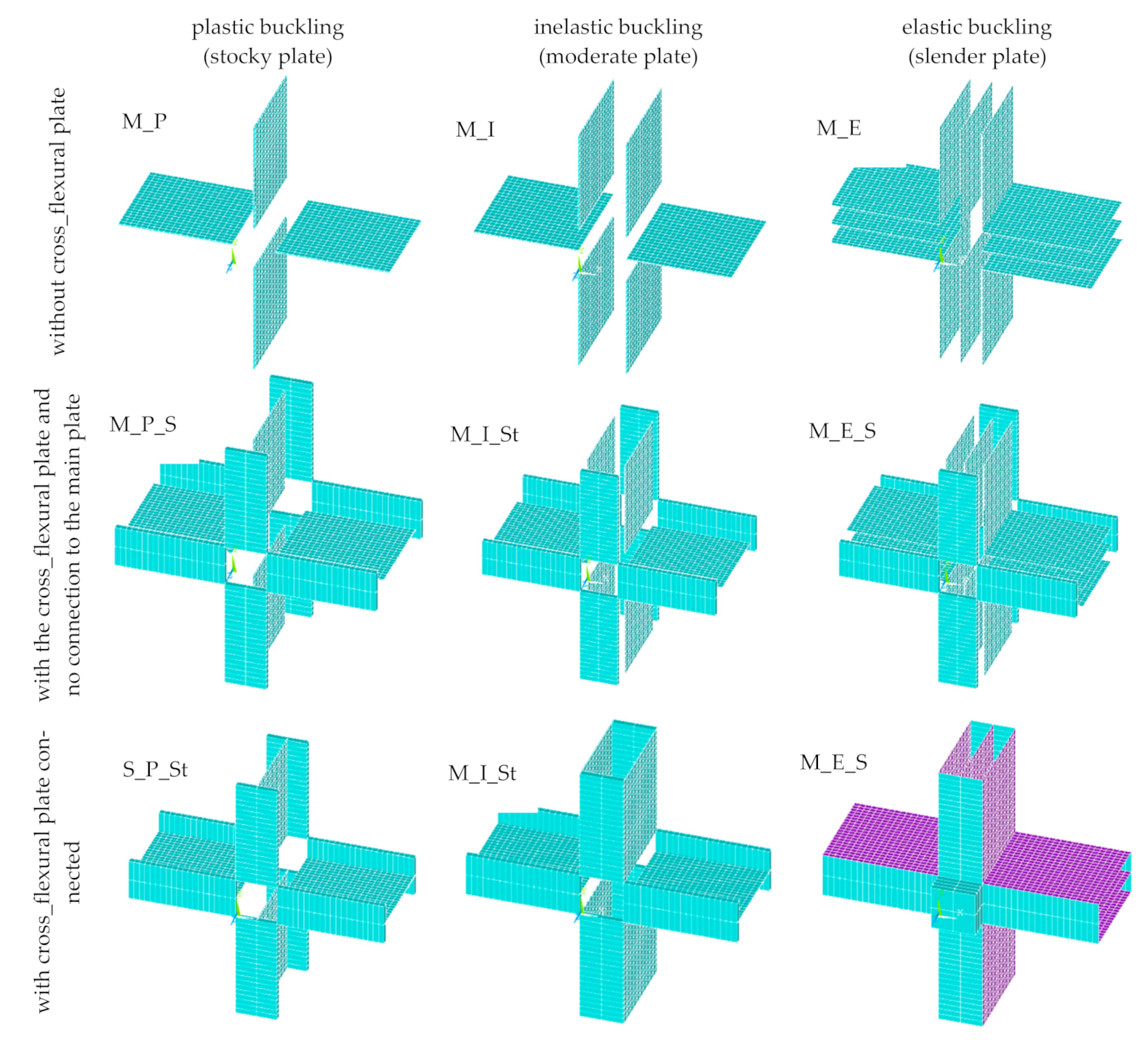
7.1. Categories of the Damper Behavior
To investigate the shearing of the main plate in dissipating the imposed energy, the yielding through the plates is shown in Figure 11. According to this figure, by adding the cross plate, the yielding spread through the plate. In other words, yielding from the bottom and top of plates moved to the middle of the plate. When the cross plate had no connection to the main plate, since the vertical edges of the plate were free, its edge did not yield but a tension field action was formed in the connected cross plate (making the plate yield). Moreover, in the main plate without a cross plate and in the cross plate not connected to the main plate, yielding started at the bottom and top of the plate, whereas it started in the middle of the plate when the cross plate was connected to the main plate. For slender plates (elastic buckling, ) without a cross plate, the dampers did not experience adequate nonlinear zones. Thus, dampers with and without cross_flexural plates are not appropriate for use as seismic dampers.
Figure 11.
The yielding status in the plates of the dampers.
Since the boundary plates support the main plates in dissipating energy, the cover plates must remain elastic. If the boundary plates experience nonlinearity, the proposed damper will not be able to dissipate energy well. Figure 12 illustrates the yielding state of the proposed damper at the ultimate displacement, confirming that the boundary cover plates remained elastic.

Figure 12.
The yielding of all dampers.
For dampers with cross_flexural plates, a flexural hinge was formed at the two ends of the plates. This finding validates the assumption that was used to predict the behavior of the damper.
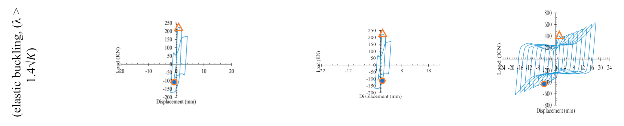
7.2. Hysterias Curve of FE Models
Figure 13 shows the hysteresis curves of the FE models. The results indicate that connecting the cross_flexural plate led to the most effective behavior of the damper, increasing the ultimate strength and reducing the ultimate displacement for models with a stocky and moderate plate (). In dampers with slender plates, , connecting the cross_flexural plate prevented fracture of the damper in the elastic zone. Moreover, it improved ultimate strength, stiffness, and energy dissipation. Therefore, slender plates can be used as seismic dampers only when connected to cross_flexural plates. In this state, the cross_flexural plate plays an important role in improving the behavior of the damper.

Figure 13.
Hysteresis curves of FE models.
7.3. Comparing the Types of Systems
Comparing the hysteresis curve of the FE models, Figure 14 confirms that connecting the cross_flexural plated to the main plate led to the issues described in Section 5.2. As shown in the figure, upon adding the cross plate to the damper, the ratio of normalized shear strength to plastic shear strength of the main plate exceeded 1. This implies that the cross plate not only changes the main plate’s behavior from flexural to shear but also contributes resisting the applied loading. Therefore, the assumption in Section 2.2 is confirmed. The results are listed in Table 2.
Figure 14.
Hysteresis curves of FE models.
Adding the cross plate to M_P models increased the strength and stiffness for all types of main plate buckling. Referring to the Table 4, for a plate with plastic buckling (), the cross_flexural plate increased the strength and stiffness by 2 and 1.06, respectively. This reveals a negligible effect on the stiffness for . For a plate with elastic buckling (), the strength and stiffness due to adding the cross plate increased by 1.2 and 2.64, respectively. Hence, by increasing λ, the effect of the cross plate on strength was reduced in comparison to stiffness. Connecting the plate to the main plate led to considerable increases in the strength and stiffness.
Table 4.
Ultimate strength and elastic stiffness of the damper.
8. Accuracy of the Proposed Relations
In Table 5, the results of the proposed damper derived from the proposed relations are compared with FE results. The proposed relations predicted the stiffness of the dampers with errors <11%. Except for the M_I damper (inelastic buckling), the ultimate strength exhibited errors <12%. In [39,53,54,55,56], the results of AISC_341 [57] were compared with FE results for predicting the shear capacity of shear links. In these studies, researchers presented relations [57] with errors of 50%. Therefore, the proposed relations in this paper for predicting the stiffness and strength of the proposed damper (as a shear link) are in good agreement with the FE results.
Table 5.
Comparing the FE results with the proposed relations.
9. Conclusions
In this paper, the behavior of a proposed damper was investigated experimentally and numerically. The results are summarized as follows:
- -
- Experimental results indicated that M_P had less strength and energy_dissipating capability than other models, as also confirmed by FE results in all types of main plate buckling.
- -
- Experimental and FE results indicated that connecting the cross plate to the web plate improved the strength and stiffness but reduced the ultimate displacement. Comparing the results of the specimen with (not connected to web plate) and without cross-flexural plates confirmed that the cross plate increased the ultimate strength by 2.65 and reduced the stiffness by 16%. The reduction in stiffness was due to the length of the web plate having a greater effect on stiffness than thickness.
- -
- Connecting the cross plate to the web plate improved the ultimate strength and stuffiness by 84% and 3.9, respectively.
- -
- In the main plate without a cross plate and with an unconnected cross plate, the yielding started at the bottom and top of the plate, whereas it started at the middle of the plate when the cross plate was connected to the main plate. For slender plates (elastic buckling, ) without a cross plate, the dampers did not experience adequate nonlinear zones. Thus, dampers with without cross flexural plates are not appropriate for use as seismic dampers.
- -
- Upon adding the cross plate to the damper, the ratio of the normalized shear strength to plastic shear strength of the main plate exceeded 1. Hence, the cross plate not only changed the main plate behavior from flexural to shear but also contributed to resisting the applied loading. Therefore, the assumption in Section 2.2 was confirmed.
- -
- For a plate with plastic buckling (), the cross_flexural plate increased the strength and stiffness by factors of 2 and 1.06, respectively, revealing a negligible effect on the stiffness for . For a plate with elastic buckling (), the strength and stiffness were increased by 1.2 and 2.64, respectively.
Author Contributions
Conceptualization, K.-J.H.; methodology, S.-H.J.; formal analysis, A.G.; investigation, A.G.; resources, S.-H.J. and A.G.; data curation, A.G. and C.-h.K.; writing—original draft preparation, A.G. and B.A.; writing—review and editing, S.-H.J.; visualization, B.A. and C.-h.K.; supervision, K.-J.H.; project administration, K.-J.H. All authors read and agreed to the published version of the manuscript.
Funding
This work was supported by a grant from the Korea Agency for Infrastructure Technology Advancement (KAIA), funded by the Ministry of Land, Infrastructure, and Transport ((Grant 21SCIP-B146946-04)).
Institutional Review Board Statement
Not applicable.
Informed Consent Statement
Not applicable.
Data Availability Statement
All research data used in this manuscript are available upon request.
Acknowledgments
This work was supported by a grant from the Korea Agency for Infrastructure Technology Advancement (KAIA), funded by the Ministry of Land, Infrastructure, and Transport ((Grant 21SCIP-B146946-04)).
Conflicts of Interest
The authors declare no conflict of interest.
References
- Sen, A.D.; Swatosh, M.A.; Ballard, R.; Sloat, D.; Johnson, M.M.; Roeder, C.W.; Lehman, D.E.; Berman, J.W. Development and evaluation of seismic retrofit alternatives for older concentrically braced frames. J. Struct. Eng. 2017, 143, 04016232. [Google Scholar] [CrossRef]
- Roeder, C.W.; Sen, A.D.; Terpstra, C.; Ibarra, S.M.; Liu, R.; Lehman, D.E.; Berman, J.W. Effect of beam yielding on chevron braced frames. J. Constr. Steel Res. 2019, 159, 428–441. [Google Scholar] [CrossRef]
- Sen, A.D.; Sloat, D.; Ballard, R.; Johnson, M.M.; Roeder, C.W.; Lehman, D.E.; Berman, J.W. Experimental evaluation of the seismic vulnerability of braces and connections in older concentrically braced frames. J. Struct. Eng. 2016, 142, 04016052. [Google Scholar] [CrossRef]
- FEMA, 351. Recommended Seismic Evaluation and Upgrade Criteria for Existing Welded Steel Moment-Frame Buildings; FEMA: Washington, DC, USA, 2000. [Google Scholar]
- Sabelli, R.; Mahin, S.; Chang, C. Seismic demands on steel braced frame buildings with buckling-restrained braces. Engineering Structures 2003, 25, 655–666. [Google Scholar] [CrossRef]
- Skalomenos, K.A.; Inamasu, H.; Shimada, H.; Nakashima, M. Development of a steel brace with intentional eccentricity and experimental validation. J. Struct. Eng. 2017, 143, 04017072. [Google Scholar] [CrossRef]
- Inamasu, H.; Skalomenos, K.A.; Hsiao, P.C.; Hayashi, K.; Kurata, M.; Nakashima, M. Gusset plate connections for naturally buckling braces. J. Struct. Eng. 2017, 143, 04017065. [Google Scholar] [CrossRef]
- Housner, G.; Bergman, L.A.; Caughey, T.K.; Chassiakos, A.G.; Claus, R.O.; Masri, S.F.; Skelton, R.E.; Soong, T.T.; Spencer, B.F.; Yao, J.T. Structural control: Past, present, and future. J. Eng. Mech. 1997, 123, 897–971. [Google Scholar] [CrossRef]
- Soong, T.T.; Dargush, G.F. Passive Energy Dissipation Systems in Structural Engineering; Wiley: Hoboken, NJ, USA, 1997. [Google Scholar]
- Symans, M.D.; Charney, F.A.; Whittaker, A.S.; Constantinou, M.C.; Kircher, C.A.; Johnson, M.W.; McNamara, R.J. Energy dissipation systems for seismic applications: Current practice and recent developments. J. Struct. Eng. 2008, 134, 3–21. [Google Scholar] [CrossRef]
- Xia, C.; Hanson, R.D. Influence of ADAS element parameters on building seismic response. J. Struct. Eng. 1992, 118, 1903–1918. [Google Scholar] [CrossRef]
- Khazaei, M. Investigation on dynamics nonlinear analysis of steel frames with steel dampers. Procedia Eng. 2013, 54, 401–412. [Google Scholar] [CrossRef][Green Version]
- TahamouliRoudsari, M.; Eslamimanesh, M.B.; Entezari, A.R.; Noori, O.; Torkaman, M. Experimental assessment of retrofitting RC moment resisting frames with ADAS and TADAS yielding dampers. Structures 2018, 14, 75–87. [Google Scholar] [CrossRef]
- Tsai, K.C.; Chen, H.W.; Hong, C.P.; Su, Y.F. Design of steel triangular plate energy absorbers for seismic-resistant construction. Earthq. Spectra 1993, 9, 505–528. [Google Scholar] [CrossRef]
- Mahmoudi, M.; Abdi, M.G. Evaluating response modification factors of TADAS frames. J. Constr. Steel Res. 2012, 71, 162–170. [Google Scholar] [CrossRef]
- Gray, M.G.; Christopoulos, C.; Packer, J.A.; De Oliveira, C. A new brace option for ductile braced frames. Mod. Steel Constr. 2012, 52, 40–43. [Google Scholar]
- Gray, M.G.; Christopoulos, C.; Packer, J.A. Cast steel yielding brace system for concentrically braced frames: Concept development and experimental validations. J. Struct. Eng. 2014, 140, 04013095. [Google Scholar] [CrossRef]
- Gray, M.G.; Christopoulos, C.; Packer, J.A. Design and full-scale testing of a cast steel yielding brace system in a braced frame. J. Struct. Eng. 2017, 143, 04016210. [Google Scholar] [CrossRef]
- Watanabe, A.; Hitomi, Y.; Saeki, E.; Wada, A.; Fujimoto, M. Properties of brace encased in buckling-restraining concrete and steel tube. In Proceedings of the Ninth World Conference on Earthquake Engineering, Tokyo, Japan, 2–9 August 1988; Volume 4, pp. 719–724. [Google Scholar]
- Kiggins, S.; Uang, C.M. Reducing residual drift of buckling-restrained braced frames as a dual system. Eng. Struct. 2006, 28, 1525–1532. [Google Scholar] [CrossRef]
- Takeuchi, T.; Hajjar, J.F.; Matsui, R.; Nishimoto, K.; Aiken, I.D. Local buckling restraint condition for core plates in buckling restrained braces. J. Constr. Steel Res. 2010, 66, 139–149. [Google Scholar] [CrossRef]
- Takeuchi, T.; Hajjar, J.F.; Matsui, R.; Nishimoto, K.; Aiken, I.D. Effect of local buckling core plate restraint in buckling restrained braces. Eng. Struct. 2012, 44, 304–311. [Google Scholar] [CrossRef]
- Palmer, K.D.; Christopulos, A.S.; Lehman, D.E.; Roeder, C.W. Experimental evaluation of cyclically loaded, large-scale, planar and 3-d buckling-restrained braced frames. J. Constr. Steel Res. 2014, 101, 415–425. [Google Scholar] [CrossRef]
- Atlayan, O.; Charney, F.A. Hybrid buckling-restrained braced frames. J. Constr. Steel Res. 2014, 96, 95–105. [Google Scholar] [CrossRef]
- Budaházy, V.; Dunai, L. Numerical analysis of concrete filled buckling restrained braces. J. Constr. Steel Res. 2015, 115, 92–105. [Google Scholar] [CrossRef]
- Ebadi Jamkhaneh, M.; Homaioon Ebrahimi, A.; Shokri Amiri, M. Seismic performance of steel-braced frames with an all-steel buckling restrained brace. Pract. Period. Struct. Des. Constr. 2018, 23, 04018016. [Google Scholar] [CrossRef]
- Abbasnia, R.; Vetr, M.G.H.; Ahmadi, R.; Kafi, M.A. Experimental and analytical investigation on the steel ring ductility. Sharif J. Sci. Technol. 2008, 52, 41–48. [Google Scholar]
- Bazzaz, M.; Andalib, Z.; Kheyroddin, A.; Kafi, M.A. Numerical comparison of the seismic performance of steel rings in off-centre bracing system and diagonal bracing system. J. Steel Compos. Struct. 2015, 19, 917–937. [Google Scholar] [CrossRef]
- Azandariani, M.G.; Abdolmaleki, H.; Azandariani, A.G. Numerical and analytical investigation of cyclic behavior of steel ring dampers (SRDs). Thin-Walled Struct. 2020, 151, 106751. [Google Scholar] [CrossRef]
- Roeder, C.W.; Popov, E.P. Inelastic behavior of eccentrically braced steel frames under cyclic loadings. STIN 1977, 78, 20375. [Google Scholar]
- Richards, P.W.; Uang, C.M. Effect of flange width-thickness ratio on eccentrically braced frames link cyclic rotation capacity. J. Struct. Eng. 2005, 131, 1546–1552. [Google Scholar] [CrossRef]
- Okazaki, T.; Engelhardt, M.D.; Hong, J.K.; Uang, C.M.; Drolias, A. Improved link-to-column connections for steel eccentrically braced frames. J. Struct. Eng. 2015, 141, 04014201. [Google Scholar] [CrossRef]
- Shayanfar, M.A.; Rezaeian, A.R.; Taherkhani, S. Assessment of the seismic behavior of eccentrically braced frame with double vertical link (DV-EBF). In Proceedings of the 14th World Conference on Earthquake Engineering, Beijing, China, 12–17 October 2008; pp. 12–17. [Google Scholar]
- Shayanfar, M.A.; Barkhordari, M.A.; Rezaeian, A.R. Experimental study of cyclic behavior of composite vertical shear link in eccentrically braced frames. Steel Compos. Struct. 2012, 12, 13–29. [Google Scholar] [CrossRef]
- Shayanfar, M.A.; Rezaeian, A.R.; Zanganeh, A. Seismic performance of eccentrically braced frame with vertical link using PBPD method. Struct. Des. Tall Spec. Build. 2014, 23, 1–21. [Google Scholar] [CrossRef]
- Bouwkamp, J.; Vetr, M.G.; Ghamari, A. An analytical model for inelastic cyclic response of eccentrically braced frame with vertical shear link (V-EBF). Case Stud. Struct. Eng. 2016, 6, 31–44. [Google Scholar] [CrossRef]
- Vetr, M.G.; Ghamari, A.; Bouwkamp, J. Investigating the nonlinear behavior of Eccentrically Braced Frame with vertical shear links (V-EBF). J. Build. Eng. 2017, 10, 47–59. [Google Scholar] [CrossRef]
- Vetr, M.G.; Ghamari, A. Experimentally and analytically study on eccentrically braced frame with vertical shear links. Struct. Des. Tall Spec. Build. 2019, 28, e1587. [Google Scholar] [CrossRef]
- Ghamari, A.; Kim, Y.; Bae, J. Utilizing an I-shaped shear link as a damper to improve the behaviour of a concentrically braced frame. J. Construct. Steel Res. 2021, 186, 1–13. [Google Scholar] [CrossRef]
- Ghamari, A.; Haeri, H.; Khaloo, A.; Zhu, Z. Improving the hysteretic behavior of Concentrically Braced Frame (CBF) by a proposed shear damper. Steel Compos. Struct. 2019, 30, 383–392. [Google Scholar]
- Zahrai, S.M.; Moslehi Tabar, A. Analytical study on cyclic behavior of chevron braced frames with shear panel system considering post-yield deformation. Can. J. Civ. Eng. 2013, 40, 633–643. [Google Scholar] [CrossRef]
- Zahrai, S.M. Cyclic testing of chevron braced steel frames with IPE shear panels. Steel Compos. Struct. 2015, 19, 1167–1184. [Google Scholar] [CrossRef]
- Kato, S.; Kim, Y.B.; Nakazawa, S.; Ohya, T. Simulation of the cyclic behavior of J-shaped steel hysteresis devices and study on the efficiency for reducing earthquake responses of space structures. J. Constr. Steel Res. 2005, 1457–1473. [Google Scholar] [CrossRef]
- Deng, K.; Pan, P.; Wang, C. Development of crawler steel damper for bridges. J. Constr. Steel Res. 2015, 140–150. [Google Scholar] [CrossRef]
- Zkaynak, H. Model proposal for steel cushions for use in reinforced concrete frames. KSCE J. Civ. Eng. 2017, 21, 2717–2727. [Google Scholar] [CrossRef]
- Xu, L.Y.; Nie, X.; Fan, J.S. Cyclic behaviour of low-yield-point steel shear panel dampers. Eng. Struct. 2016, 126, 391–404. [Google Scholar] [CrossRef]
- Basler, K. Strength of plate girders in shear. J. Struct. Div. 1961, 87, 151–180. [Google Scholar] [CrossRef]
- Ozcelik, Y.; Clayton, P. Strip model for steel plate shear walls with beam-connected web plates. Eng. Struct. 2017, 136, 369–379. [Google Scholar] [CrossRef]
- ASHTO, American Association of State Highway and Transportation Officials. LRFD Bridge Design Specifications, 3rd ed.; ASHTO: Washington, DC, USA, 2005. [Google Scholar]
- Applied Technology Council (ATC). Guidelines for Cyclic Seismic Testing of Components of Steel Structures; ATC-24; ATC: Redwood, CA, USA, 1992. [Google Scholar]
- ASTM D3999-91. Standard Test Methods for the Determination of the Modulus and Damping Properties of Soils Using the Cyclic Triaxial Apparatus; American Society for Testing and Materials: West Conshohocken, PA, USA, 2003. [Google Scholar]
- Nguyen, T.; Indraratn, B.; Singh, M. Dynamic parameters of subgrade soils prone to mud pumping considering the influence of kaolin content and the cyclic stress ratio. Transp. Geotech. 2021, 29, 100581. [Google Scholar] [CrossRef]
- Ghadami, A.; Pourmoosavi, G.; Ghamari, A. Seismic design of elements outside of the short low-yield-point steel shear links. J. Constr. Steel Res. 2021, 178, 106489. [Google Scholar] [CrossRef]
- Azad, S.K.; Topkaya, C. A review of research on steel eccentrically braced frames. J. Constr. Steel Res. 2017, 128, 53–73. [Google Scholar] [CrossRef]
- Daneshmand, A.; Hashemi, B. Performance of intermediate and long links in eccentrically braced frames. J. Constr. Steel Res. 2012, 70, 167–176. [Google Scholar] [CrossRef]
- Dusicka, P.; Itani, A.M.; Buckle, I.G. Cyclic behavior of shear links of various grades of plate steel. J. Struct. Eng. 2010, 136, 370–378. [Google Scholar] [CrossRef]
- AISC 341-16. Seismic Provisions for Structural Steel Buildings; American Institute of Steel Constriction: Chicago, IL, USA, 2016. [Google Scholar]
Publisher’s Note: MDPI stays neutral with regard to jurisdictional claims in published maps and institutional affiliations. |
© 2021 by the authors. Licensee MDPI, Basel, Switzerland. This article is an open access article distributed under the terms and conditions of the Creative Commons Attribution (CC BY) license (https://creativecommons.org/licenses/by/4.0/).