
Conceptual and Preliminary Design of a Shoe Manufacturing Plant

 ,
,
Abstract
1. Introduction
2. The Shoe Industry
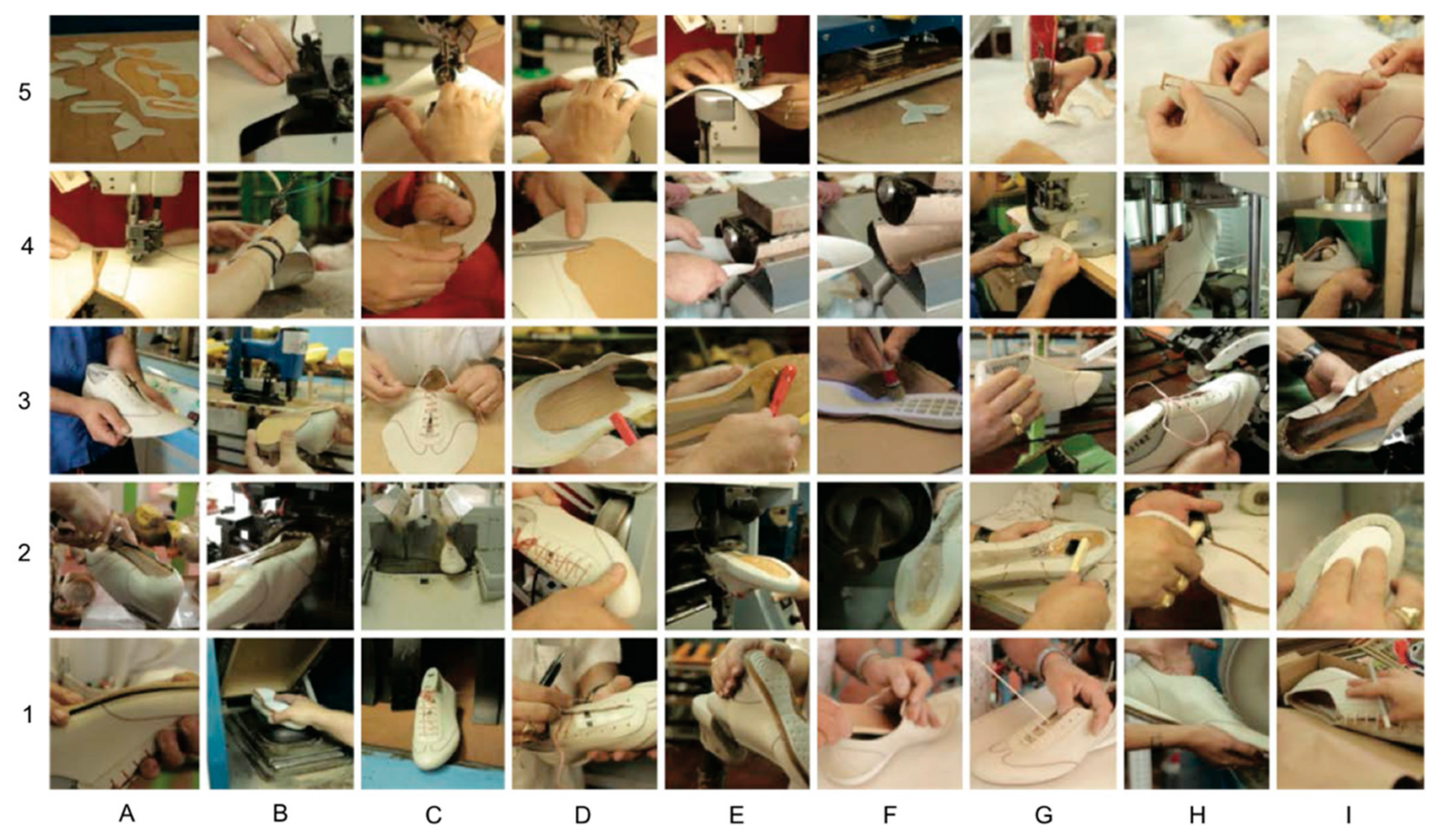
Shoe Production
- Cutting: The different pieces (of leather, synthetic canvas, suede, textile, etc.) that will form the upper are cut (Figure 1(A5)). In addition, cut pieces are prepared for the following processes by doing guiding marks or temporary unions among others.
- Stitching: Upper pieces are stitched together with a sewing machine (Figure 1(B5–A4)).
- Assembly: Upper is prepared by placing heel counter, welt, and toecap if required. Some pieces are pre-shaped and mounted using a last and then, the upper is bonded to the outsole (Figure 1(B4–C1)).
- Finishing: In this final step, the product gets its final appearance. Processes of cleaning, insole, and laces placement, etc., are done. Finally, the product is packed and stored in the warehouse (Figure 1(D1–I1)).
3. Literature Review
4. Methodology and Materials
4.1. Expert System Approach
4.2. Software Simulation Approach
4.3. Time Estimation for Process Operations
5. Case Study 1: The Direct-Injection Process
5.1. Time Estimation for Process Operations
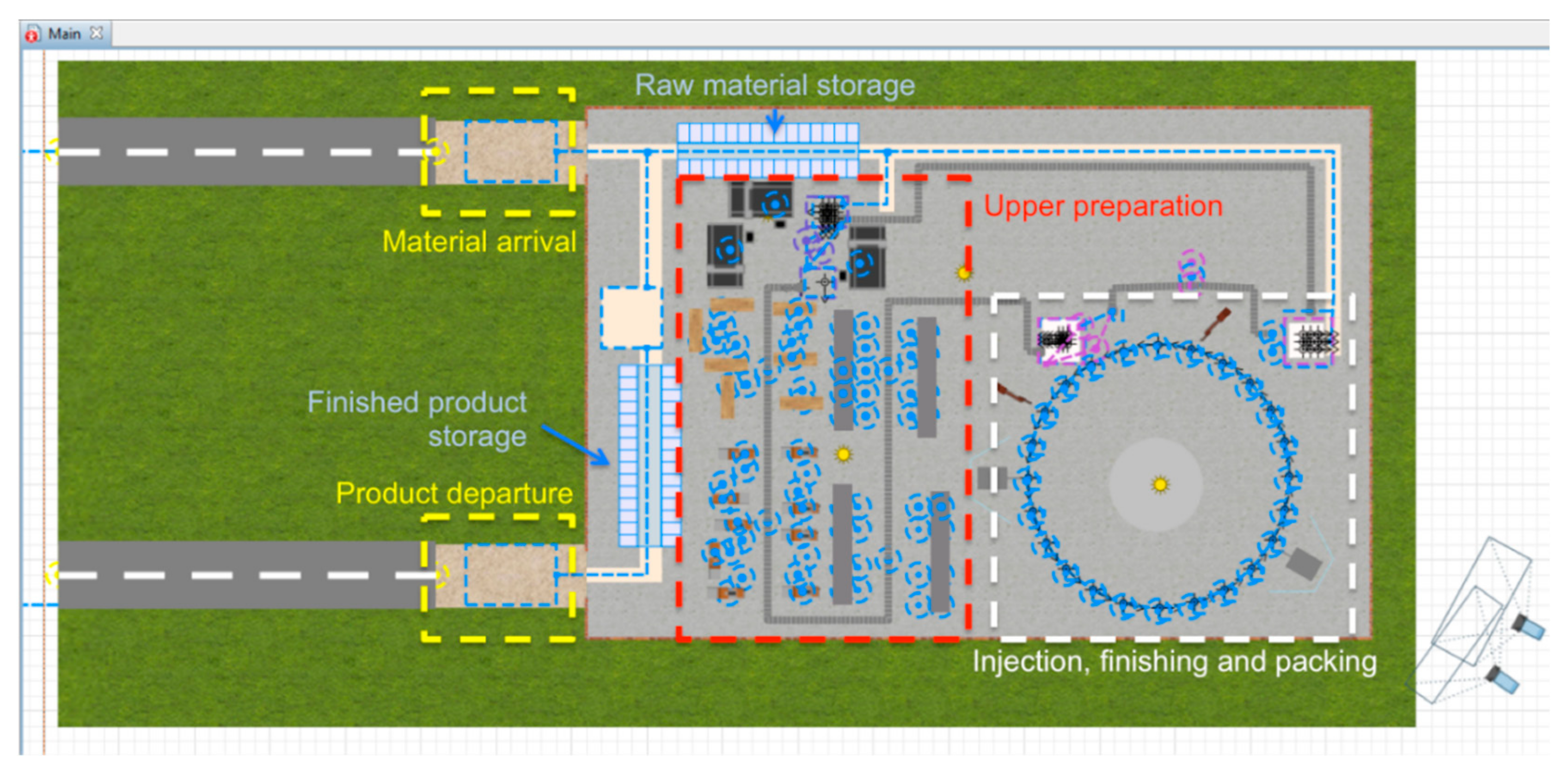
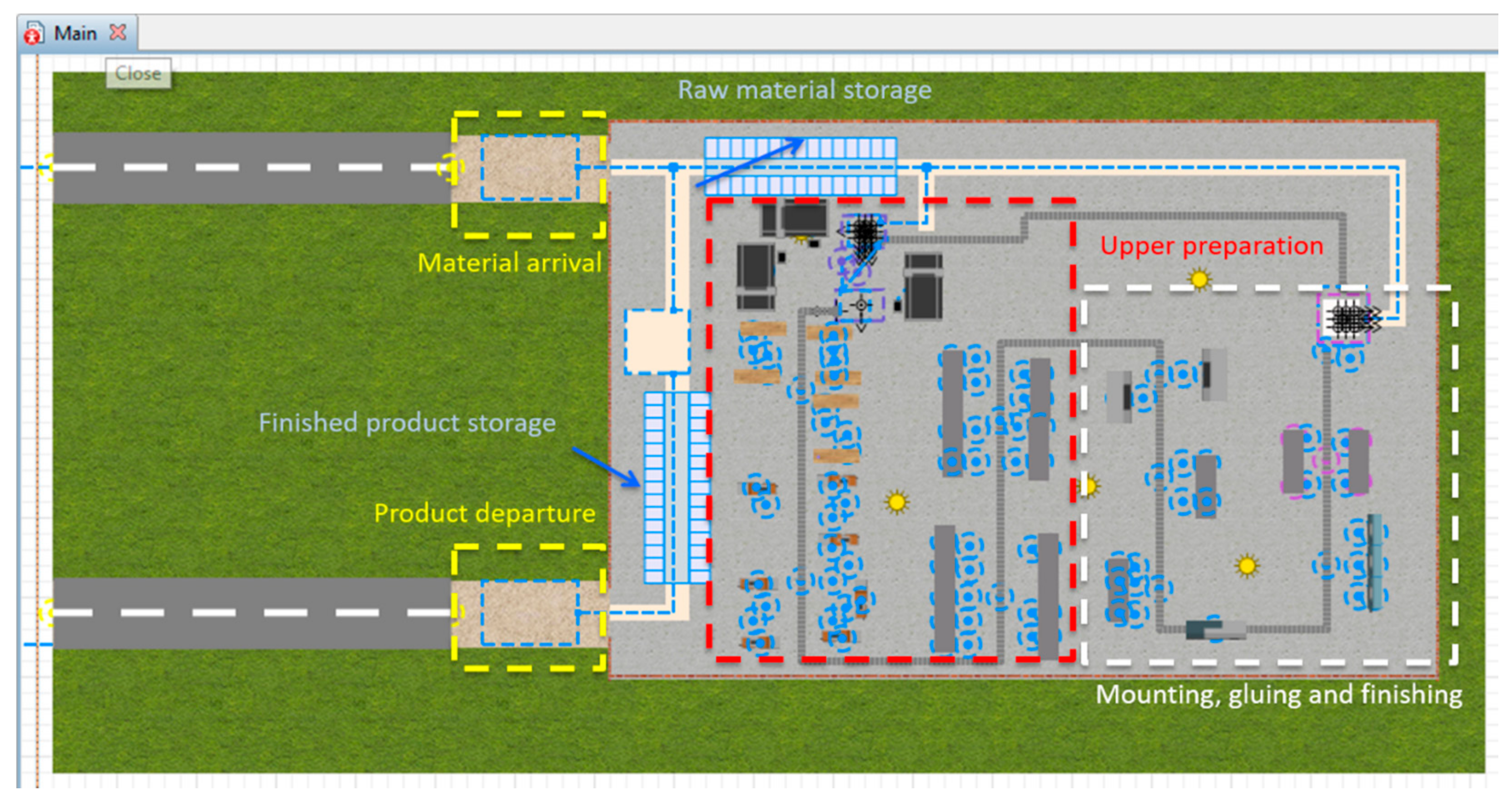
5.2. Modelling Results
- Delivery, storage, and shipping of materials and products: First of all, a system for the delivery and storage of raw material is modelled. Either the storage capacity or the interval delivery time can be controlled through the parameters that have been previously defined in order to avoid stock shortage.
- Limiting factor: Secondly, the ‘Rotary’ agent that represents the rotary injection machine is configured. Simultaneously, the relationship between the rotary machine and the rest of the system is defined. Figure 5 shows the logical blocks used for modelling the rotary injection machine movement.
- Pre limiting factor operations: After having properly defined the limiting factor, the operations prior to that point must be modelled and the number of resources needed to keep the rotary machine at full capacity established.
- Post limiting factor: Finally, the operations of finishing and packing are modelled. At this moment, it is necessary to establish the number of resources needed to extract every product injected from the rotary injection machine without getting new queues.
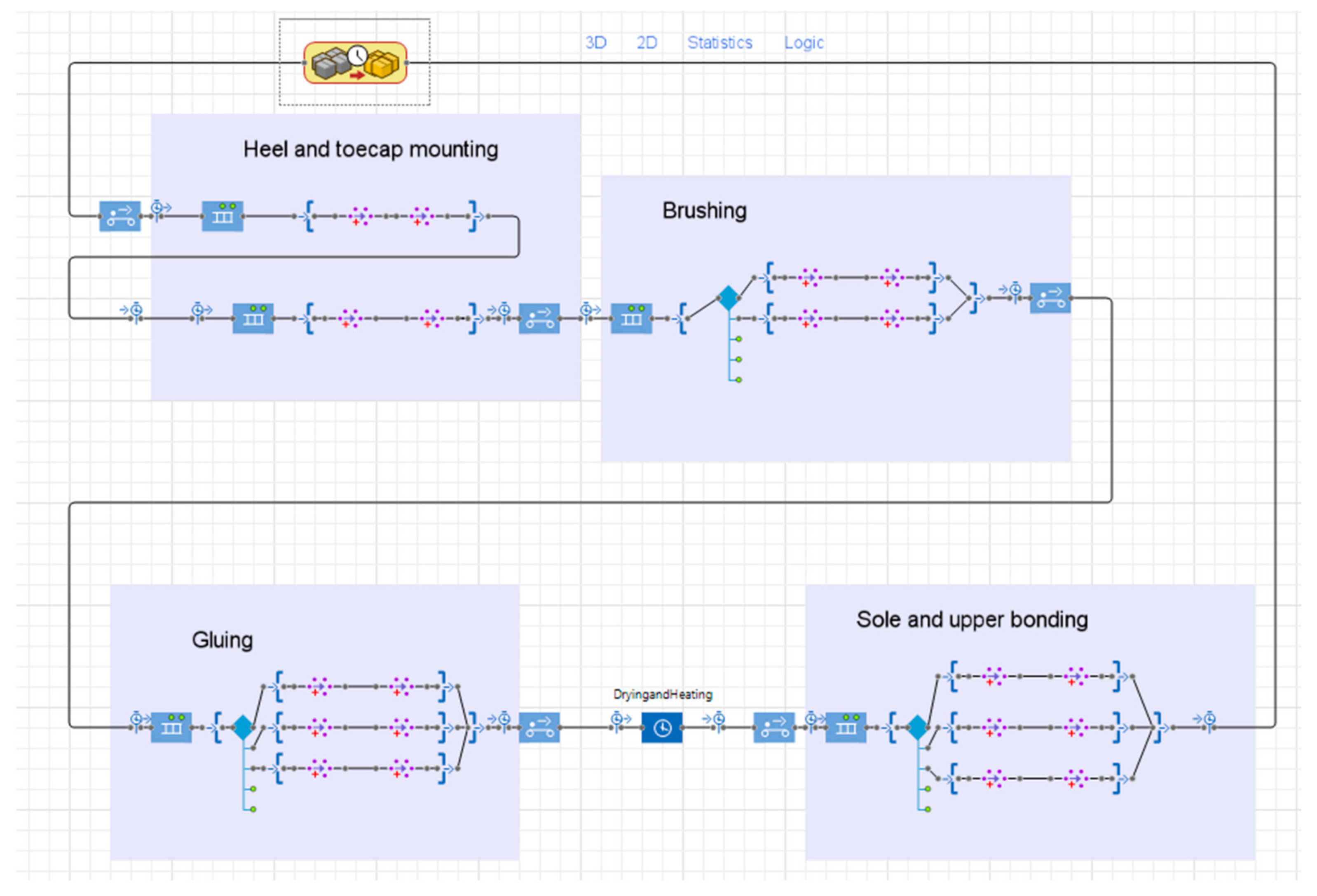
6. Case Study 2: The Mounting-and-Cementing Process
6.1. Input Data
6.2. Modelling Results
7. Comparison between Both Processes
8. Conclusions
- Proposal of productive design alternatives: resources and productivity of both analysed methods (direct-injection and mounting-and-cementing).
- Industrial process design when exact or complete data does not exist.
- Space needs for different resources, especially for production and storage (finished product and raw materials).
Author Contributions
Funding
Institutional Review Board Statement
Informed Consent Statement
Data Availability Statement
Acknowledgments
Conflicts of Interest
References
- Kidd, A.L. Knowledge Acquisition for Expert Systems: A Practical Handbook; Springer: Cham, Switzerland, 1987. [Google Scholar]
- Chan, F.T.; Chan, H. Design of a PCB plant with expert system and simulation approach. Expert Syst. Appl. 2005, 28, 409–423. [Google Scholar] [CrossRef]
- Borshchev, A.; Filippov, A. AnyLogic—Multi-paradigm simulation for business, engineering and research. In Proceedings of the 6th IIE Annual Simulation Solutions Conference, Orlando, FL, USA, 15–16 March 2004. [Google Scholar]
- Ivanov, D. Operations and Supply Chain Simulation with Anylogic 7.2: Decision-Oriented Introductory Notes for Master Students; Berlin School of Economics and Law: Berlin, Germany, 2016. [Google Scholar]
- Grigoryev, I. AnyLogic 7 in Three Days; CreateSpace: Scotts Valley, CA, USA, 2016. [Google Scholar]
- Global Industry Analysts. The Global Footwear Market. 2019. Available online: https://www.strategyr.com/market-report-footwear-forecasts-global-industry-analysts-inc.asp (accessed on 30 September 2021).
- Schmél, F. Structure of Production Costs in Footwear Manufacture; United Nations Industrial Development Organization: Vienna, Austria, 2003. [Google Scholar]
- Boër, C.R.; Dulio, S. The EUROShoE project. In Mass Customization and Footwear: Myth, Salvation or Reality? Springer: London, UK, 2007. [Google Scholar]
- Jeng, Y.-R.; Liu, D.-S.; Yau, H.-T. Fast numerical algorithm for optimization mold shape of direct injection molding process. Mater. Manuf. Process. 2013, 28, 689–694. [Google Scholar] [CrossRef]
- Denkena, B.; Scherger, S. A concept for shoe last manufacturing in mass customisation. CIRP Ann. 2005, 54, 341–344. [Google Scholar] [CrossRef]
- Jatta, F.; Zanoni, L.; Fassi, I.; Negri, S. A roughing/cementing robotic cell for custom made shoe manufacture. Int. J. Comput. Integr. Manuf. 2004, 17, 645–652. [Google Scholar] [CrossRef]
- Lee, C.-Y.; Kao, T.-L.; Wang, K.-S. Implementation of a robotic arm with 3d vision for shoes glue spraying system. In Proceedings of the 2nd International Conference on Computer Science and Artificial Intelligence, Shenzhen, China, 8–10 December 2018; pp. 562–565. [Google Scholar]
- Mendez, J.B.; Perez-Vidal, C.; Heras, J.V.S.; Perez-Hernandez, J.J. Robotic pick-and-place time optimization: Application to footwear production. IEEE Access 2020, 8, 209428–209440. [Google Scholar] [CrossRef]
- Das, B.; Grady, R.M. Industrial workplace layout design. An application of engineering anthropometry. Ergonomics 1983, 26, 433–447. [Google Scholar] [CrossRef] [PubMed]
- Ulutas, B.; Islier, A.A. Dynamic facility layout problem in footwear industry. J. Manuf. Syst. 2015, 36, 55–61. [Google Scholar] [CrossRef]
- Linko, S. Expert systems—What can they do for the food industry? Trends Food Sci. Technol. 1998, 9, 3–12. [Google Scholar] [CrossRef]
- Ali, J.M.; Hussain, M.A.; Tade, M.O.; Zhang, J. Artificial Intelligence techniques applied as estimator in chemical process systems: A literature survey. Expert Syst. Appl. 2015, 42, 5915–5931. [Google Scholar]
- Iymen, G.; Tanriver, G.; Hayirlioglu, Y.Z.; Ergen, O. Artificial intelligence-based identification of butter variations as a model study for detecting food adulteration. Innov. Food Sci. Emerg. Technol. 2020, 66, 102527. [Google Scholar] [CrossRef]
- Jha, K.; Doshi, A.; Patel, P.; Shah, M. A comprehensive review on automation in agriculture using artificial intelligence. Artif. Intell. Agric. 2019, 2, 1–12. [Google Scholar] [CrossRef]
- Eryilmaz, M.; Kuakci, A.; Gavranovic, H.; Findik, F. Análisis de líneas de espera a través de teoría de colas y simulación. Sci. Tech. 2010, 17, 56–61. [Google Scholar]
- Covas, J.T.M. Production Line Balancing Simulation: A Case Study in the Footwear Industry. Master’s Thesis, University of Porto, Porto, Portugal, 2014. [Google Scholar]
- Thomopoulos, N.T. Assembly Line Planning and Control; Springer: Singapore, 2014. [Google Scholar]
- Bangsow, S. (Ed.) Use Cases of Discrete Event Simulation; Springer: Cham, Switzerland, 2012. [Google Scholar]
- Nisanci, H.I.; Sury, R.J. Production analysis by simulation in a shoe manufacturing factory. Int. J. Prod. Res. 1980, 18, 31–41. [Google Scholar] [CrossRef]
- Dang, Q.-V.; Pham, K. Design of a footwear assembly line using simulation-based ALNS. Procedia CIRP 2016, 40, 596–601. [Google Scholar] [CrossRef][Green Version]
- Zangiacomi, A.; Zhijian, L.S.; Boer, C.L. Process planning and scheduling for mass customised shoe manufacturing. In Proceedings of the 6th IIE Annual Simulation Solutions Conference, Orlando, FL, USA, 15–16 March 2004. [Google Scholar]
- Matelli, J.A.; Bazzo, E.; da Silva, J.C. An expert system prototype for designing natural gas cogeneration plants. Expert Syst. Appl. 2009, 36, 8375–8384. [Google Scholar] [CrossRef]
- Dym, C.L.; Levitt, R.E. Knowledge-Based Systems in Engineering; McGraw-Hill: New York, NY, USA, 1991. [Google Scholar]
- Kumar, S.L. Knowledge-based expert system in manufacturing planning: State-of-the-art review. Int. J. Prod. Res. 2018, 57, 4766–4790. [Google Scholar] [CrossRef]
- Gabbar, H.A.; Suzuki, K.; Shimada, Y. Plant object-orientated model formalization: A case study: HDS plant design. Des. Stud. 2003, 24, 101–108. [Google Scholar] [CrossRef]
- Alting, L. Manufacturing Engineering Processes; Marcel Dekker: New York, NY, USA, 1994. [Google Scholar]
- Colledani, M.; Terkaj, W.; Tolio, T.; Tomasella, M. Development of a conceptual reference framework to manage manufacturing knowledge related to products, processes and production systems. In Methods and Tools for Effective Knowledge Life-Cycle-Management; Springer: Cham, Switzerland, 2008; pp. 259–284. [Google Scholar]
- ProModel. ProModel Process Simulator. 2020. Available online: http://promodel.com.mx/promodel/ (accessed on 30 September 2021).
- Arena Simulation. Manufacturing Simulation Software. 2020. Available online: https://www.arenasimulation.com/industry-solutions/industry/manufacturing-simulation-software (accessed on 30 September 2021).
- Simio. Simio Simulation Software. 2020. Available online: https://www.simio.com/software/simulation-software.php (accessed on 30 September 2021).
- FlexSim. FlexSim Problem Solved. 2020. Available online: https://www.flexsim.com/flexsim/ (accessed on 30 September 2021).
- AnyLogic. AnyLogic Manufacturing Simulation Software. 2020. Available online: https://www.anylogic.com/manufacturing/ (accessed on 30 September 2021).
- Ivanov, D.; Rozhkov, M. Coordination of production and ordering policies under capacity disruption and product write-off risk: An analytical study with real-data based simulations of a fast moving consumer goods company. Ann. Oper. Res. 2017, 107, 1–21. [Google Scholar] [CrossRef]
- Gianesello, P.; Ivanov, D.; Battini, D. Closed-loop supply chain simulation with disruption considerations: A case-study on Tesla. Int. J. Inventory Res. 2017, 4, 257–280. [Google Scholar] [CrossRef]
- SimplicityWorks. SimplicityWorks Europe S.L. 2021. Available online: http://www.simplicity.works/ (accessed on 15 November 2021).


| Task | Direct Injection Mounting and Cementing Time per Shoe (s) | |
|---|---|---|
| Material placement and projections adjustment | 6.5 | |
| Cutting | 39 | |
| Upper marking | 30 | |
| Tongue marking | 9 | |
| Milling | 30 | |
| Temporary unions | 45 | |
| Toecap sewing | 37 | |
| Quarter sewing | 67 | |
| Heel sewing | 37 | |
| Gluing between tongue, upper, and lining | 52 | |
| Gluing between upper and lining | 47 | |
| Gluing foam in tongue | 22 | |
| Top moulder | 52 | |
| Heel moulder | 52 | |
| Eyelets | 36 | |
| Top mounting | - | 17 |
| Heel and shank mounting | - | 17 |
| Marking and brushing | - | 26 |
| Gluing sole and upper | - | 40 |
| Drying and glue activation | - | 20 |
| Press outsole bonding | - | 38 |
| Flash cutting | 10 | - |
| Last removal | 6 | |
| Cleaning | 13 | |
| Insole and shoelace | 51 | |
| Packing | 14 | |
| Cutting | 39 | - |
| Number of stations | 24 |
| Cycle of time (s) | 16 |
| Movement time between stations (s) | 2 |
| Number of injectors | 2 |
| Process | Operations | Time per Product | N Workers | Efficiency | |||
|---|---|---|---|---|---|---|---|
| Operation Time | Total Time | DI | M&C | DI | M&C | ||
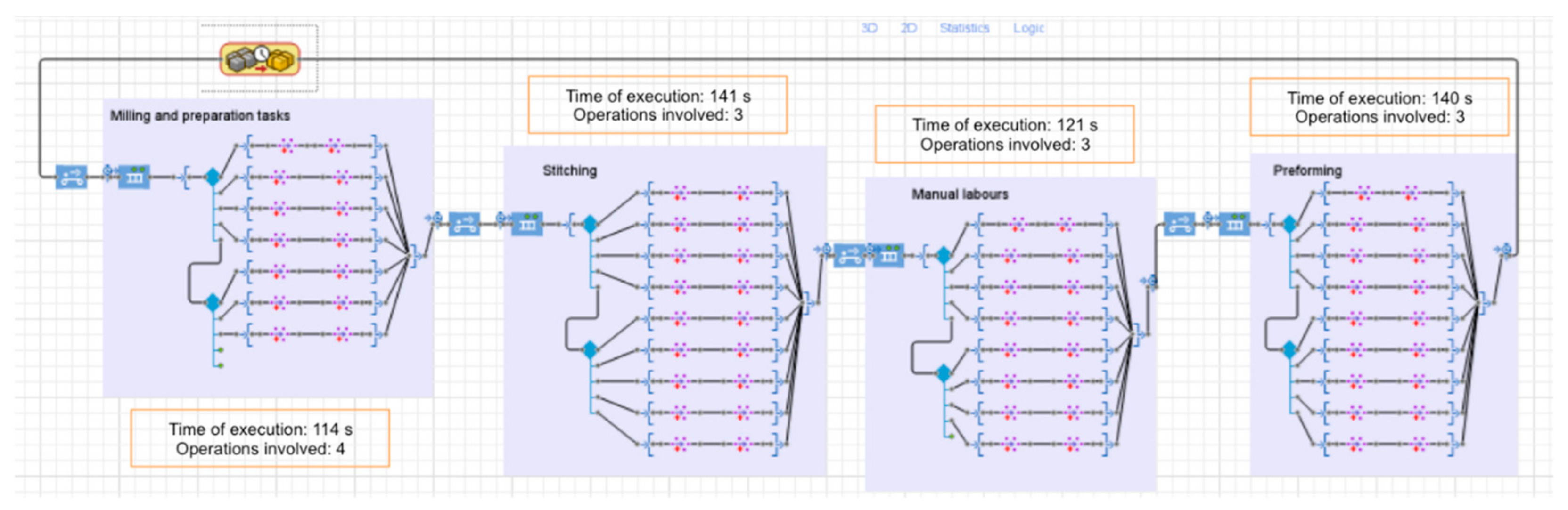
| Milling and preparations tasks | Upper marking | 30 | 114 | 7 | 6 | 88.57% | 86.67% |
| Tongue marking | 9 | ||||||
| Milling | 30 | ||||||
| Temporary unions | 45 | ||||||
| Toecap sewing | 37 | ||||||
| Stitching | Quarter sewing | 67 | 141 | 9 | 8 | 83.93% | 82.21% |
| Heel sewing | 37 | ||||||
| Gluing tongue, upper, and lining | 52 | ||||||
| Manual labours | Gluing upper and lining | 47 | 121 | 8 | 7 | 81.70% | 80.60% |
| Gluing foam | 22 | ||||||
| Top moulder | 52 | ||||||
| Preshaping | Heel moulder | 52 | 140 | 9 | 8 | 81.96% | 79.04% |
| Eyelets | 36 | ||||||
| Last removal | 6 | ||||||
| Finishing | Cleaning | 13 | 70 | 4 | 4 | 88.00% | 78.00% |
| Insole and shoelace | 51 | ||||||
| Process | Time per Product (s) | N of Workers | Efficiency |
|---|---|---|---|
| Toecap mounting | 17 | 1 | 89.00% |
| Heel and shank mount | 17 | 1 | 86.00% |
| Brushing and marking | 26 | 2 | 67.50% |
| Gluing sole and upper | 40 | 3 | 76.00% |
| Press outsole bounding | 38 | 3 | 61.66% |
| One Shift Labour Day (8 h) | N of Workers | Productivity Ratio Shoes per Worker per Day | |
|---|---|---|---|
| Direct injection | 1574 pairs of shoes | 37 | 36.60 |
| Mounting-and-cementing | 1320 pairs of shoes | 43 | 28.08 |
Publisher’s Note: MDPI stays neutral with regard to jurisdictional claims in published maps and institutional affiliations. |
© 2021 by the authors. Licensee MDPI, Basel, Switzerland. This article is an open access article distributed under the terms and conditions of the Creative Commons Attribution (CC BY) license (https://creativecommons.org/licenses/by/4.0/).
Share and Cite
Borrell Méndez, J.; Cremades, D.; Nicolas, F.; Perez-Vidal, C.; Segura-Heras, J.V. Conceptual and Preliminary Design of a Shoe Manufacturing Plant. Appl. Sci. 2021, 11, 11055. https://doi.org/10.3390/app112211055
Borrell Méndez J, Cremades D, Nicolas F, Perez-Vidal C, Segura-Heras JV. Conceptual and Preliminary Design of a Shoe Manufacturing Plant. Applied Sciences. 2021; 11(22):11055. https://doi.org/10.3390/app112211055
Chicago/Turabian StyleBorrell Méndez, Jorge, David Cremades, Fernando Nicolas, Carlos Perez-Vidal, and Jose Vicente Segura-Heras. 2021. "Conceptual and Preliminary Design of a Shoe Manufacturing Plant" Applied Sciences 11, no. 22: 11055. https://doi.org/10.3390/app112211055
APA StyleBorrell Méndez, J., Cremades, D., Nicolas, F., Perez-Vidal, C., & Segura-Heras, J. V. (2021). Conceptual and Preliminary Design of a Shoe Manufacturing Plant. Applied Sciences, 11(22), 11055. https://doi.org/10.3390/app112211055