1. Introduction
The exploitation of petroleum, natural gas, geothermal, and other resources cannot be separated from drilling engineering [
1]. With the depletion of shallow oil, natural gas, geothermal, and other resources, the goal of exploration and development has gradually deepened, and the drilling depth of drilling engineering, rock hardness, compressive shear strength, and abrasiveness of the drilled stratum have increased rapidly. Influenced by drilling depth and rock formation characteristics, a problem will eventually arise when the bit torque is insufficient to break the formation, causing the bit to stop rotating instantaneously [
2,
3,
4]. If the ground turntable is rotating normally when this happens, then the applied energy will be temporarily stored in the drill string, resulting in the drill string becoming twisted more and more tightly and the cutting torque being transmitted to the drill bit, causing it to become larger [
5,
6]. When torque is required for shearing and when the stratum breaks, then the energy of the drill string will be released instantly, causing the drill string and the drill bit to rotate violently; in other words, stick-slip vibration will occur [
7,
8,
9]. Stick-slip vibration not only affects the service performance of the drill pipe and the service life of a drill bit, but it also causes drilling engineering losses [
10,
11,
12].
The torsional impactor TorkBuster was jointly developed by the United Diamond, Canada, and Ulterra, United States, the representative of torsional impactors in foreign countries. The TorkBuster torsional impactor has a good use effect, but its use cost is high in China due to patent protection [
7,
8,
9]. The domestic torsional impactor is represented by the SLTIDT torsional impactor developed by the Drilling Technology Research Institute of the Shengli Petroleum Administration Bureau in 2012. The torque impactor has a good use effect with independent intellectual property rights, but the sand and gravel deposition in the drilling fluid can easily lead to the abnormal operation of the tool [
7,
8,
9].
This paper designs a new type of torsional impactor that can be directly installed on the drill bit and that can apply periodic torsional impact to the drill bit to generate continuous and stable torque in cooperation with the drill string, assist the drill bit in efficiently breaking rocks, reduce or eliminate the stick-slip vibration of the drill bit, improve the penetration rate, and prolong the service life of the drill bit.
2. Structure and Working Principle of New Torsional Impactor
2.1. Structure
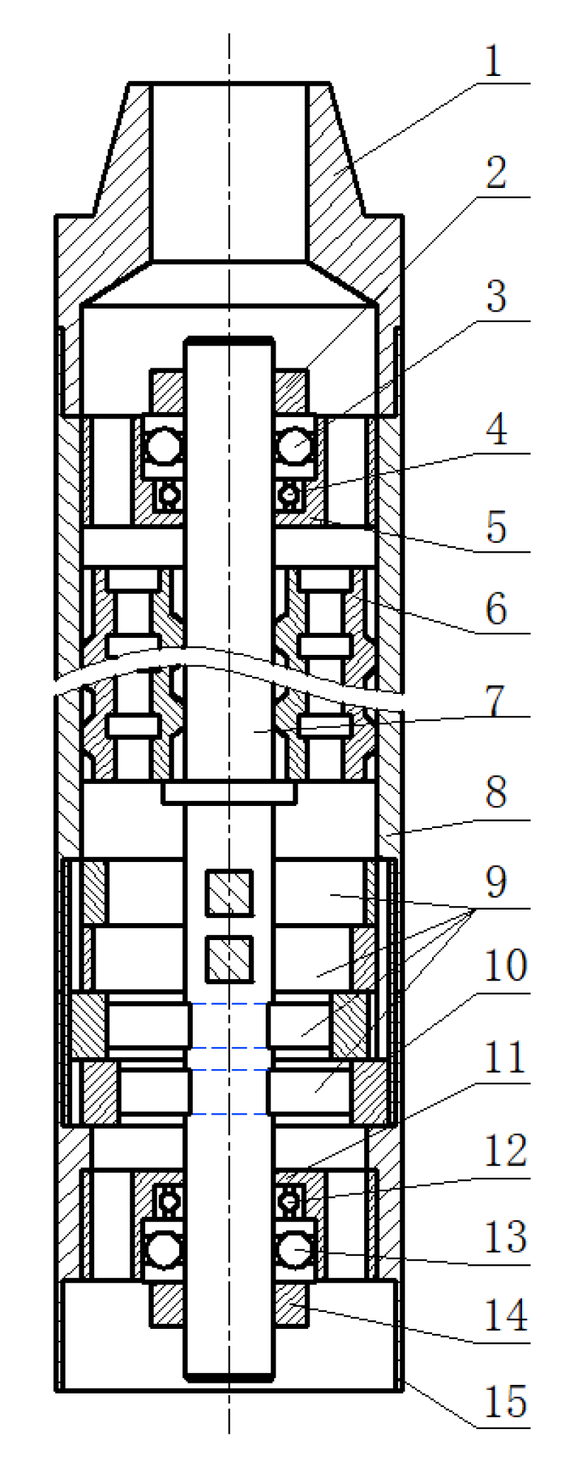
As shown in
Figure 1, the new torsional impactor mainly includes the drill pipe joint, nut, thrust ball bearing, deep groove ball bearing, bearing seat, turbine, transmission shaft, upper joint, impact anvil, impact hammer, connecting shaft, torque transmission joint, and lower joint, which constitute the upper and lower connecting devices, supporting devices, and torque generating devices of the torsional impactor.
The upper and lower connecting devices are composed of drill pipe joints, upper joints, torque transmission joints, and lower joints, which are mainly used to connect drill pipes, drill bits, and other tools. Additionally, the supporting device is composed of an upper joint, bearing seat, thrust ball bearing, deep groove ball bearing, and nut, which are mainly used to support the impeller, transmission shaft, and torsional impact generator.
A torsion generating device is mainly composed of an impact anvil, impact hammer, and a connecting shaft, which can provide torsion with the cooperation of impeller. The upper and lower connecting devices are combined to form a cylindrical shell, and the supporting device is connected to the cylindrical shell, which is responsible for supporting the parts that are installed in the cylindrical shell, and the torque generating device cooperates with the impeller, which is responsible for converting the fluid energy into torsional impact mechanical energy.
2.2. Working Principle
The working principle of the new torsional impactor is as follows: the ground drilling rig drives the drill pipe to rotate, and the drill pipe transmits torque to the drill bit through the drill pipe joint, the upper joint, the torque transmission joint, and the lower joint, thus realizing the rotation of the drill bit and crushing rocks. The ground drilling fluid driving the device transports the drilling fluid while carrying energy to the hollow channel of the drill pipe joint through the hollow drill pipe channel, and the drilling fluid flows to the turbine and makes contact with the turbine blades through the waist hole on the bearing seat. The turbine converts the fluid energy of the drilling fluid into mechanical energy for the rotation of the turbine rotor, and the transmission shaft rotates synchronously with the turbine rotor driven by the turbine rotor. The torque generating device is installed on the transmission shaft through a square hole and square shaft, and the rotating transmission shaft drives the connecting shaft in the torque generating device so that they can together with the punching hammer through the square hole and square shaft. Because of the special structure of the impact anvil (wall thickness is inconsistent and impact surface is designed), the rotating impact hammer can impact the impact anvil and can produce an impact force and impact vibration. When the torque-generating devices are arranged in pairs that are adjacent to each other, then they can generate pairs of impact force and impact vibrations that are basically equal in size, different in action points, and opposite in direction. This pair of impact forces constitutes torsion, while the impact vibration that is generated by cooperation constitutes torsion impact. Torsional impact is finally transmitted to the drill bit through the impact anvil, the torque transmission joint, and the lower joint in order to realize torsional impact drilling.
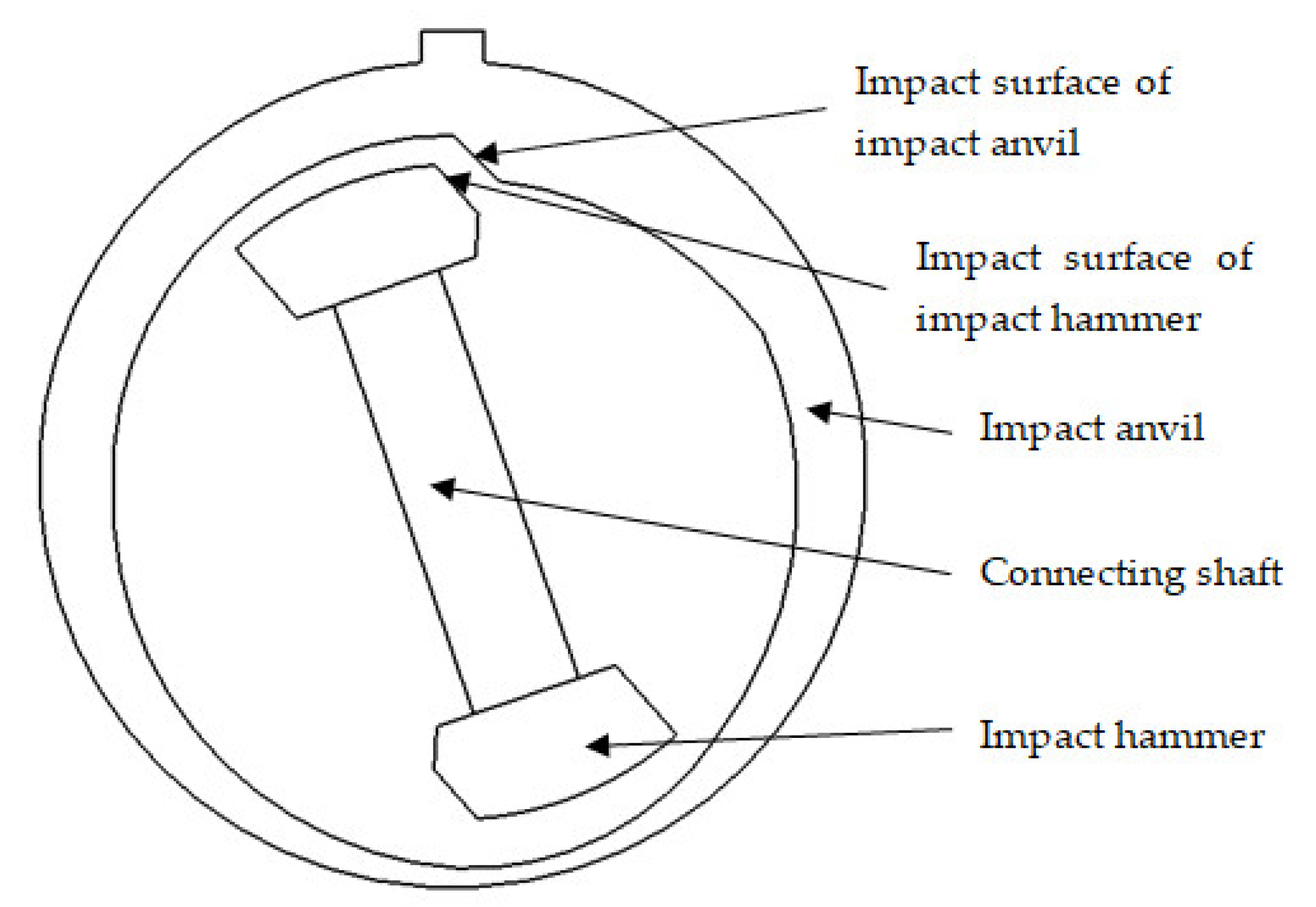
The torsion generator is a key component in the impactor, the structure of which is shown in
Figure 2 and is mainly composed of an impact anvil, impact hammer, and connecting shaft. The working principle is as follows: a single torque generator is composed of four parts, including one 1 connecting shaft, two impact hammers, and one impact anvil. The impact anvil is ring-shaped with protruding keys on the outer part and has a different inner radius, so the thickness of the impact anvil ring wall is different. The part where the impact anvil has protruding keys is the thickest, and the impact surface is designed here, and the thinnest part is designed on the opposite side. The purpose is that when the impact surface of the impact hammer comes into contact and impacts the impact surface of the impact anvil, according to the principle of acting force and reaction force, the impact surface of the impact hammer is subjected to an acting force that is perpendicular to the inclined plane, which can be decomposed into a tangential acting component of the impact hammer and axial-acting component of the connecting shaft. The axial-acting component drives the connecting shaft and the impact hammer to move along the axial direction of the connecting shaft to the thinnest part of the impact anvil wall, thus enabling the impact hammer to bypass the impact surface at the thickest part of the impact anvil and allowing it to continue to rotate after completing the impact task. After the impact hammer rotates 180°, the other impact hammer rotates to the impact surface of the impact anvil, and the other impact hammer also impacts the impact surface of the impact anvil, which also produces tangential and axial force components. Due to the axial force components, the connecting shaft and two impact hammers are driven to move axially and to continue to rotate together under the drive of the transmission shaft, bypass the impact surface of the impact anvil, and then enter the next cycle. A single torsion generator can only generate impact force and impact vibration. To generate torsion force, it is necessary to design and install the torsion generator in pairs, so that the generated pairs of impact forces are basically equal in magnitude and opposite in direction and so their actions are not in the same straight line, which meets the requirements of torsion action, allowing torsion action to be generation. In addition, due to the impact vibration in the impact process, the device can generate torsion impact.
2.3. Performance Characteristics
(1)The new torsional impactor is a pure mechanical structure that does not have any electronic components and rubber parts, allowing it to work in high temperature (such as geothermal exploration and development) environments;
(2)The impact force that is produced by the impactor can be adjusted by selecting turbine blades with different performance parameters, designing different impact surface angles, and designing impact hammers with different qualities;
(3)The torsional impactor has a simple structure, which can convert the hydraulic energy of fluid into torsional mechanical energy under a certain frequency and can directly transmit it to the drill bit. Even if the torsional impactor fails, it will not affect the drilling operation or drilling fluid circulation;
(4)Due to the smooth flow passage when the drilling fluid passes through the diversion holes of the turbine and bearing seat during the flowing process, the drilling hydraulic pressure drop is small;
(5)The torsional impact direction of the torsional impactor is consistent with the rotary direction of the drill bit, which is beneficial to the drill bit being able to cut and break through rocks.
3. Work Methods
The “stick-slip” phenomenon often occurs during the drilling process of hard rock in deep wells. The existing research results show that the “stick-slip” phenomenon results in the reduced performance of the drill pipe, the shortened life of drill bit, reduced drilling efficiency, and increased drilling cost. Installing the torque impactor and the drill bit above and applying periodic, high-frequency and high-torque torsional impact can effectively assist the drill bit to break rock efficiently, improve drilling efficiency, and reduce drilling cost [
13,
14,
15,
16,
17]. Therefore, the performance of the torque impactor is mainly reflected in the following three parameters, namely impact force, impact torque, and impact frequency [
5,
9,
10].
3.1. Impact Frequency
Combined with the structure and working principle of the torsion impactor designed in this paper, it can be seen that the impact frequency of the torsion impactor is related to the rotational speeds of the transmission shaft and the turbine rotor, so the working rotational speed of the turbine is related to the impact frequency of the torsion impactor.
At present, there are four types of turbodrills with outer diameters of 240 mm, 195 mm, 175 mm, and 165 mm in China [
14], and their related parameters are shown in
Table 1 [
18,
19].
It can be seen from
Table 1 that the working speed of different types of turbodrills in China is 400~600 rot/min, which is characterized by high speed and large torque. When the transmission shaft rotates once as a cycle, then the impact frequency is:
where
f is the impact frequency, Hz
; Vz is working speed of turbodrill, rot/min; and
n is the number of torsion-generating devices installed in the torsion impactor.
3.2. Impact Force
According to the structure and working principle of the torque generator, the impact force
F is related to impact hammer mass, impact hammer speed, and impact surface angle. After the impact hammer collides with the impact anvil, because of the existence of the impact-inclined plane, the impact-inclined plane will generate an impact reaction force against the impact hammer. One component of the impact reaction force will make the impact hammer move in the axial direction of the connecting shaft, so that the impact hammer will pass over the impact anvil inclined plane, and it will then continue to rotate under the drive of the transmission shaft until it meets the impact-inclined plane here, thus completing the periodic impact task. During this impact process, the motion energy of the impact hammer is transferred to the impact anvil. According to the principle of momentum conservation:
where
F is the impact force that is generated by torque generator, N; ∆
t is the contact time between impact hammer and impact anvil during impact, s;
m is the impact hammer mass, kg; and
Vx is the linear velocity of impact hammer, m/s.
where
ω is the angular velocity, rad/s;
Vz is the rotation speed of the transmission shaft, rot/min; and
r is the rotary radius of impact hammer, mm.
In addition, when the impact hammer acts with the impact anvil, it comes into contact with an inclined plane (i.e., there is an impact angle
α, 0° <
α < 90°); in other words, part of the force that is generated in the impact process is in the radial direction of the impact anvil, and this part of force cannot work on the impact anvil. Only the force in the tangential direction of the impact anvil can work on the impact anvil. Therefore, the impact force f acting on the torsional impact that is generated by the torsional impactor is:
where
F is the impact force, N; Δ
t is the impact contact time of two parts, s; and
α is the impact angle, °.
3.3. Impact Torque
Impact torque is the product of the impact force and the turning radius of the impact hammer. As torque-generating devices are installed in pairs, the impact torque
M is:
where
M is the impact torque, N·m;
F is the impact force, N; and
r is the rotary radius of the impact hammer, mm.
4. Results
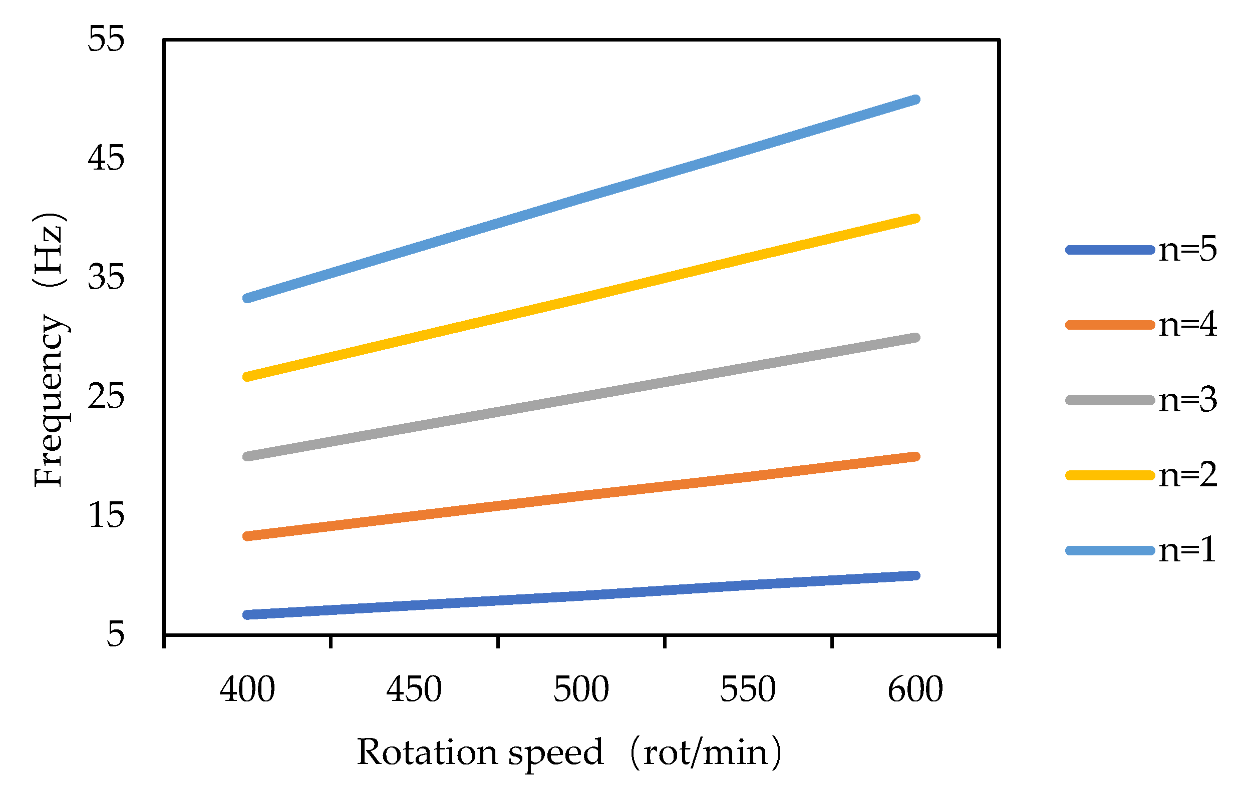
According to formula (1), the working speed range of the turbine, and the number of installed torque generators, the relationship between the impact frequency of the torque impactor, the working speed of the turbine, and the logarithm installed in the torque generators is shown in
Figure 3 below.
It can be seen from
Figure 3 that the impact frequency of the torsional impactor increases with the increasing working speed of the turbine and the installation number of torsional the impact-generating devices. According to the calculation results shown in the figure and the structure of the torsional impactor, it is recommended that the working speed of the turbine should be 500~600 rot/min or above, the installation logarithm of the torsional impact generator should be 3~4 pairs, and the impact frequency f should be in the range of 24~40 Hz in order to obtain high-frequency torsional impact.
When the outer diameter of the turbodrill is 195 mm and when the structural parameters of the parts are reasonably designed, it can be determined that the distance between the two hammers (center of gravity distance) in the torque generator can be 120~140 mm and the rotating radius
r of the hammers can 60~70 mm according to Equations (2)–(4). The impact angle
α determines the magnitude of the impact force, and when
α = 0°, torsional impact cannot be produced. When
α = 90°, it is difficult for the impact hammer to cross the impact surface of the impact anvil after the first time, and the impact process cannot continue. With
r = 60 mm and turbine speed
Vz of 500 rot/min, then the impact contact time Δ
t of the impact hammer and the impact anvil is about 0.001 s [
13], and the relationship between impact force and impact hammer mass m and impact angle
α can analyzed, with the results being shown in
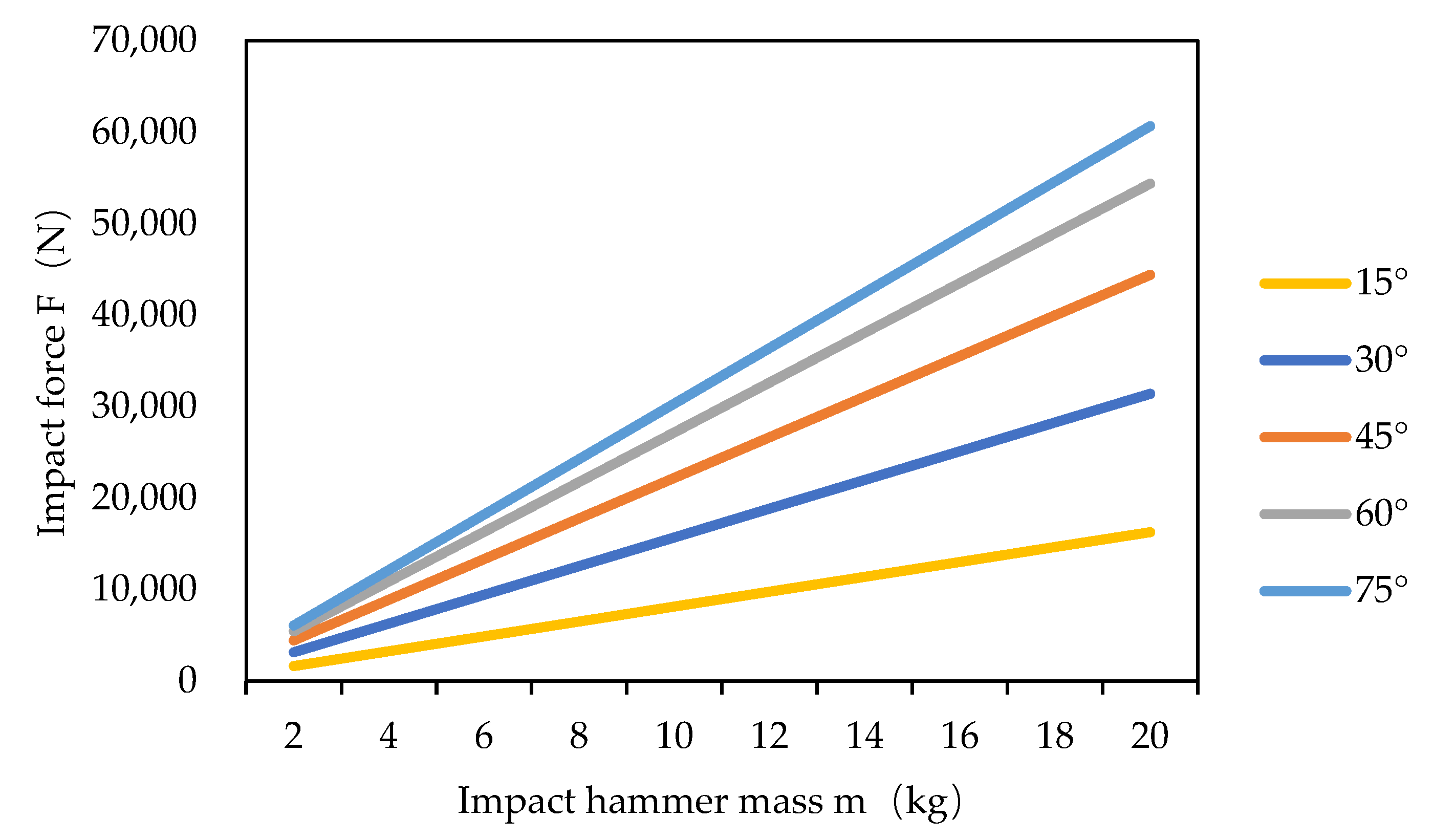
Figure 4.
It can be seen from
Figure 4 that the impact force
F increases with the increase of the impact angle
α (0° <
α < 90°), and when the impact angle
α is larger, the slope of the straight line is larger. This indicates that a larger impact angle is beneficial to produce a larger impact force in the range of values, but an excessively large impact angle
α will affect the time that is needed for the impact hammer to cross the inclined plane of the impact anvil, which would further affect the impact frequency. It can also be seen from
Figure 4 and Equation (4) that the impact force increases with the increase of the hammer mass, the rotation speed of the transmission shaft, the rotation radius of the hammer, and the action time of the hammer and anvil. According to the illustrated results and the designed torsional impactor structure, it is recommended that the impact angle
α be in the range of 30°~60°, the impact weight be in the range of 6~14 kg, and the impact force be in the range of 9420~38,096 N in order to obtain a larger impact force.
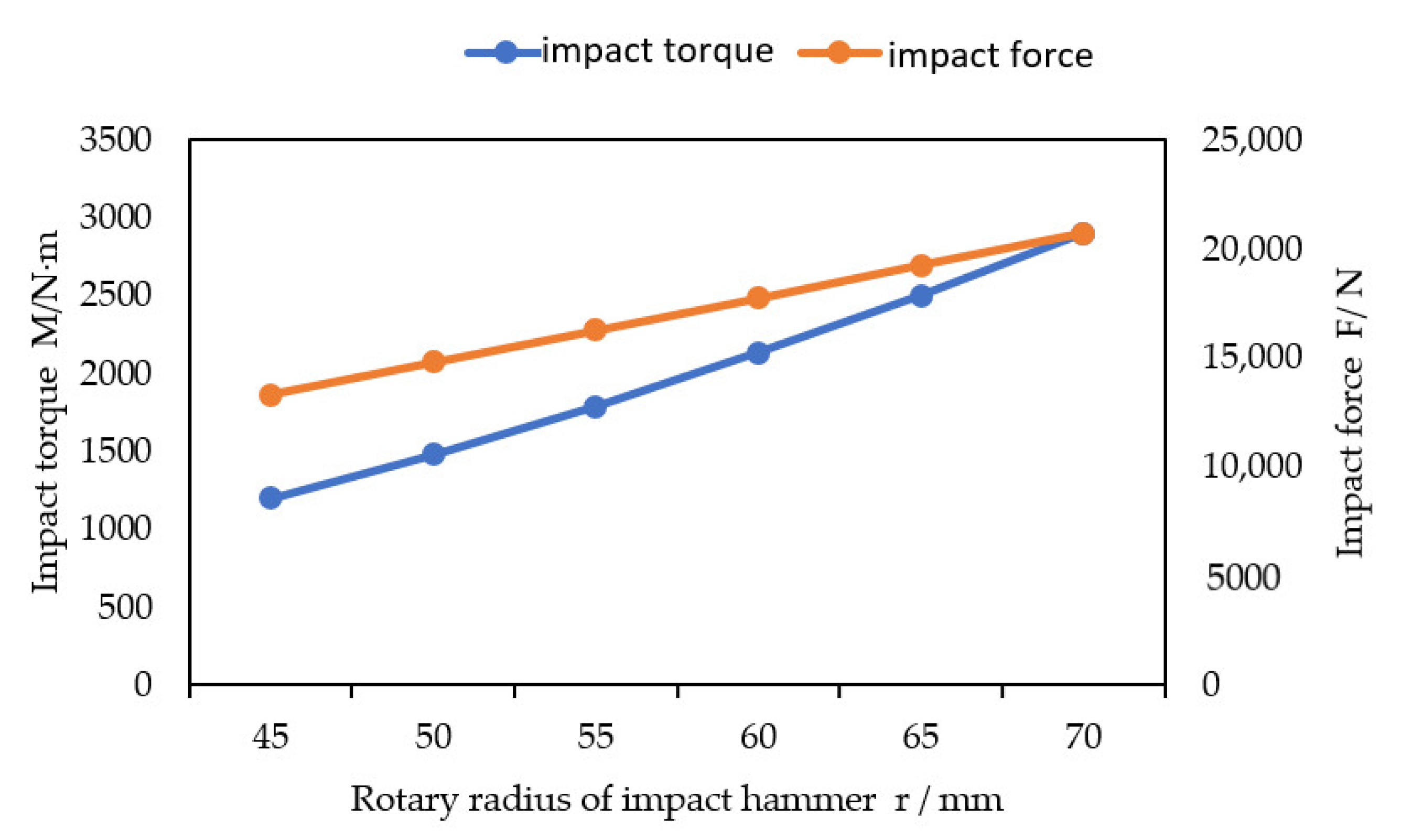
According to Equation (5), when
Vz is 500 rot/min, the impact angle
α is 45°, the
π is 3.14,
m is 8 kg, and the Δ
t is 0.001 s, the relationship between the rotating radius
r and impact force
F and impact torque
M is as it is shown in
Figure 5.
It can be seen from
Figure 5 that all of the parameters that affect the impact force may also affect the impact torque. Under the condition that the other parameters are unchanged, the impact torque
M is directly proportional to the square of the rotary radius
r of the impact hammer, indicating that increasing the rotary radius
r of the impact hammer is the most beneficial to increasing the impact torque
M. However, according to the structure of the torsional impactor, the rotary radius
r of the impact hammer, which is limited by the diameter of the drilling tool, cannot be increased at will, so it is recommended that the value range of the rotary radius of the impact hammer be 50~65 mm. According to the above values, the impact torque can reach 1480~2501 N·m once.
5. Case Study
A torsion impactor is a downhole auxiliary rock breaking tool that is used to connect the drill bit and the drill collar. In order to ensure a normal connection between the drill bit and the drill collar, it is necessary to consult relevant industry standards and to determine the outer diameter and joint thread parameters of the tool. According to the type of drill collar and drill bit, the main parameters of other parts can be designed, and the torsional impact performance can analyzed, with a torsional impactor with an outer diameter D is 203 mm being used as an example.
With the outer diameter of torsion impactor being designed as 203 mm, the inner diameter
d and outer diameter
D1 of the drill collar are selected to be 71.4 mm and 203.2 mm, respectively, while the corresponding outer diameter of drill collar selected as
D2 is 311 mm for drilling operations with a torsional impactor. According to the structure of the torsional impactor shown in
Figure 1, turbine model 195 was selected. As shown in
Table 1. The model 195 turbine has a working speed of 430~560 rot/min and a working torque of 3200~5600 N·m.
According to the analysis in
Section 3.1, the impact frequency of the torsion impactor designed in this paper is mainly related to the rotation speed of the turbine rotor and the pairs of the torque impact generator. According to the turbine model speed range that was selected, the turbine speed
Vz is set as 500 rot/min. Approximately 2~4 pairs of torsional impact generators can be installed as required. Here, the installation logarithm is three pairs. It can be seen from Formula (1) that the impact frequency
f of the torsional impact generator is 25 Hz.
According to the analysis in
Section 3.2, the impact force
F of the torsion impactor that was designed in this paper is mainly related to the impact hammer mass
m, the impact hammer speed
Vz (i.e., the speed at which the turbine rotor drives the transmission shaft), the impact angle
α, and the impact hammer rotation radius
r. According to the selected turbine model, the impact hammer speed
Vz is 500 rot/min, as above. According to the structure and limited space of the torsional impact generating device, the mass of the impact hammer is taken as
m is 6 kg; in order to ensure that there is enough axial force to ensure that the impact hammer moves axially after impacting the anvil, the impact angle
α should be taken as 45°; according to the outer diameter of the torsion impactor, the structure of the torsion generator and the value range of the rotary radius
r of the impact hammer as well as the rotary radius
r of the impact hammer is taken as 60 mm, and the impact force
F is about 13,320 N
, according to the calculation of Formula (4).
According to the analysis in
Section 3.3, the impact torque
M of the torsion impactor designed in this paper is mainly related to the impact force
F and the rotation radius
r of the impact hammer, so the parameters related to the impact force are all related to the impact torque. According to the above impact force calculation results of 13,319.88 N and the radius of gyration
r of the hammer of 60 mm, it can be calculated that the impact torque
M is 1598 N·m, as per formula (5).
To sum up, the related parameters of the structure and performance of the torsional impactor are all shown in
Table 2.
6. Conclusions
(1)In view of the stick-slip phenomenon during drilling, a new type of torsional impactor is proposed, which can provide circumferential torque, generate circumferential torsional impact vibration, and reduce stick-slip of drill string. The torsion impactor of the new structure is a pure mechanical structure with a simple structure, convenient processing, low-cost manufacturing, and no electronic components or rubber parts, allowing the torsional impactor designed here to work in high-temperature (about 300 °C) environments. Under the same input, parts with different structural parameters can be selected to adjust to different outputs. The impact direction is consistent with the rotary direction of the bit, which is beneficial to the bit shear rock breaking.
(2)According to the structure and working principle of the newly designed torque impactor, the relationship between the impact frequency, impact force, impact torque, and related parameters is theoretically analyzed. The results show that the impact frequency f is directly proportional to the transmission shaft speed Vz and the number of n of the installation of the torque impact generator. The impact force F is directly proportional to the sine value of the impact angle α (i.e., sinα), the hammer mass m, the hammer speed (i.e., transmission shaft rotation speed) Vz, and the hammer rotation radius r and is inversely proportional to the action time Δt of the impact hammer and the anvil. The impact torque M is directly proportional to impact force F and the impact hammer rotation radius r; in other words, all of the parameters affecting the impact force F may affect the impact torque. Under the condition that the other parameters remain unchanged, the impact torque M is directly proportional to the square of the impact hammer’s rotation radius r, indicating that increasing the impact hammer rotation radius r is the most conducive to increasing the impact torque M.
(3)According to the analysis results that indicate the parameters of the drill collar and drill bit, the outer diameter parameters of the torsional impactor were selected, and the other related structure and performance parameters of the torsional impactor were obtained through the calculation and analysis of an example. This article lays a foundation for further theoretical research and experimental research on the torsional impactor and provides a reference for the design and testing of the torsional impactor discussed here.


