Article

Sensorless Predictive Current Control of a Permanent Magnet Synchronous Motor Powered by a Three-Level Inverter

School of Electrical Engineering, Nantong University, Nantong 226019, China
*
Author to whom correspondence should be addressed.
Appl. Sci. 2021, 11(22), 10840; https://doi.org/10.3390/app112210840
Submission received: 8 October 2021 / Revised: 2 November 2021 / Accepted: 15 November 2021 / Published: 16 November 2021

Abstract

:
Permanent magnet synchronous motors and their relevant control techniques have become more and more prevalent in electric vehicle driving applications because of their outstanding performance. This paper studies a simple and effective sensorless scheme based on a current observer for a permanent magnet synchronous motor powered by a three-level inverter, which avoids the injection of a high-frequency signal and the observation of back-electromotive force. In this way, a current observer is constructed to observe d–q-axes currents by relying on an extended-current model. Thereafter, the position and speed of the machine can be extracted from two PI controllers associated with the d–q-axes current-tracking errors. Meanwhile, it takes into account the model predictive current control with neutral-point voltage balance to maintain the stability of the three-level inverter system. In general, this scheme realizes sensorless operation in a full-speed domain and is no longer limited by the types of inverter and method used.

1. Introduction

Among various types of motor drives for EVs, a permanent magnet synchronous motor (PMSM) drive is attractive due to its commercial merits, such as its high efficiency and high power density [1,2,3,4]. In terms of PMSM drive technologies, traditional control techniques mainly consist of vector control (VC) and direct torque control (DTC) [5,6]. A PMSM drive relying on VC can perform comparably in dynamic characteristics to a direct current machine drive, while requiring complex coordinate transformation and significantly depending on precise machine parameters. In addition, a DTC drive suffers from the drawback of extensive calculation and greater real-time requirements, although it is simpler in structure. In comparison to the aforementioned techniques, model predictive control (MPC) possesses key features, namely, quick responsiveness, multi-objective evolutionary capability, and a simple principle [7,8,9], with this method having gained significant interest in recent years. On the other hand, the three-level, neutral-point-clamped (3L-NPC) inverter has been applied to motor drives [10], owing to its superiorities in voltage distortion, semiconductor stress, and switching frequency [11,12,13,14]. The aforementioned control techniques have been actively extended to a 3L-NPC-powered PMSM drive. When traditional methods are chosen, an additional control loop is required to keep neutral-point voltage (NPV) balance, complicating the overall control system. When aiming to eliminate the additional control loop, MPC is undoubtedly the most feasible option because of its effectiveness in terms of solving such an optimization problem with multi-objectives.
Regardless of the control strategies employed and the inverter’s topologies, installing a position sensor is normally required and is essential for an EV application. As such, once the sensor or the connecting cable breaks down, the machine, and hence the vehicle, will be out of control. For this reason, integrating a sensorless position control as an alternative option is necessary to ensure the safety of the EV when the position sensor is faulty. Conventional sensorless position control methods can be partitioned into two methodologies for different speed ranges: a back-electromotive force (BEMF)-based scheme for mid- and/or high- speed regions, and a magnetic saliency-based scheme for the low-speed region. For example, in [15], a sensorless control was created based on an improved high-frequency injection (HFI) and mainly functions to estimate motor position information as well as realize predictive current control. In this manner, the control performance and the accuracy of the position estimation are highly contingent on the injected signal frequency. Although this method can be used at an injection frequency up to a quarter of the PWM switching frequency, it also suffers from high-frequency torque ripples, and an unfavorable control performance when a high speed is required. Since the machine used for an EV application is usually required to operate in the whole speed range in practice, some blended position estimation strategies combining the above two methodologies have been recognized as future methods of meeting these requirements. A previous study [16] developed a virtual HFI method, where the high-powered sensorless control is associated with the precise automatic tracking performance of maximum-torque-per-ampere (MTPA) by constructing a virtual q-axis inductance. Additionally, in [17], a quadratic extended back-electromotive force (QBEMF) model was developed for a universal full-speed sensorless control. By incorporating the injection-based method with model-based position estimations, it enables QBEMF to work as a self-demodulator. To be specific, this scheme estimates the rotor position using diverse HFI voltages at low speed, while, as the rotor speed increases, the position estimation is still accomplished by the same observer avoiding any injections. Nevertheless, it should be noted that the sensorless schemes in [16,17] are all firmly tied to the use of a modulator (SVPWM or SPWM) and will be inoperable if the MPC method is applied due to the absence of said modulator.
Additionally, incorporating sensorless control methods and a 3L-NPC inverter scheme into a PMSM drive can greatly extend the application scope, improving performance and reliability. To this end, [18] implemented a sensorless control for a 3L-NPC drive, which was based on an extended Kalman filter. The information of both speed and flux was obtained using the extended Kalman filter to take the place of the sampled ones. Then, the prediction model utilized the estimated information, avoiding the measurement noise accordingly. However, the extended Kalman filter was horrifically computation-intensive, which is very demanding for digital implementation.
In light of the above analyses, this paper proposes a simple and effective position-estimation scheme reliant on a current observer, which is constructed on a d–q frame. Firstly, the voltage vector applied to the inverter is obtained using the current prediction model, and then their d–q-axes components are obtained through coordinate transformation. Thereafter, a current observer is constructed to observe the d–q-axes currents. On this basis, the position and speed of the machine can be extracted from two PI controllers associated with the tracking errors of d–q-axes current. In this condition, the proposed sensorless control can effectively operate the PMSM drive within the full speed domain and is not limited by the types of inverter and method used. Moreover, because this strategy senses fewer parameters and processes fewer calculations, it can be readily implemented into embedded systems.
This paper illustrates the study of the proposed sensorless control based on the following parts. In Section 2, the model of the PMSM fed by a three-level NPC inverter is constructed in detail. Then, in Section 3, the proposed sensorless predictive current control is elaborated upon, as well as the current and rotor position observers. Experimental results are presented in Section 4. Finally, a conclusion is given in Section 5.

2. Model of the Three-Level, NPC Inverter-Fed PMSM

This paper concerns the three-phase PMSM, whose dynamic model of synchronous rotating reference frame is given by
u d u q = R ω e L q ω e L d R i d i q + L d 0 0 L q d d t i d i q + 0 ω e ψ f
where ud and uq represent the stator voltages; id and iq represent the stator current; Ld and Lq represent the stator inductance; the subscripts d and q represent the components in the d and q axes, respectively; ωe denotes the electrical rotor speed; ψf denotes the flux linkage of the permanent magnet; R denotes the resistance of stator windings.
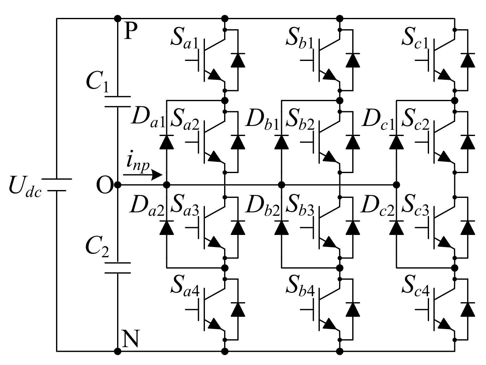
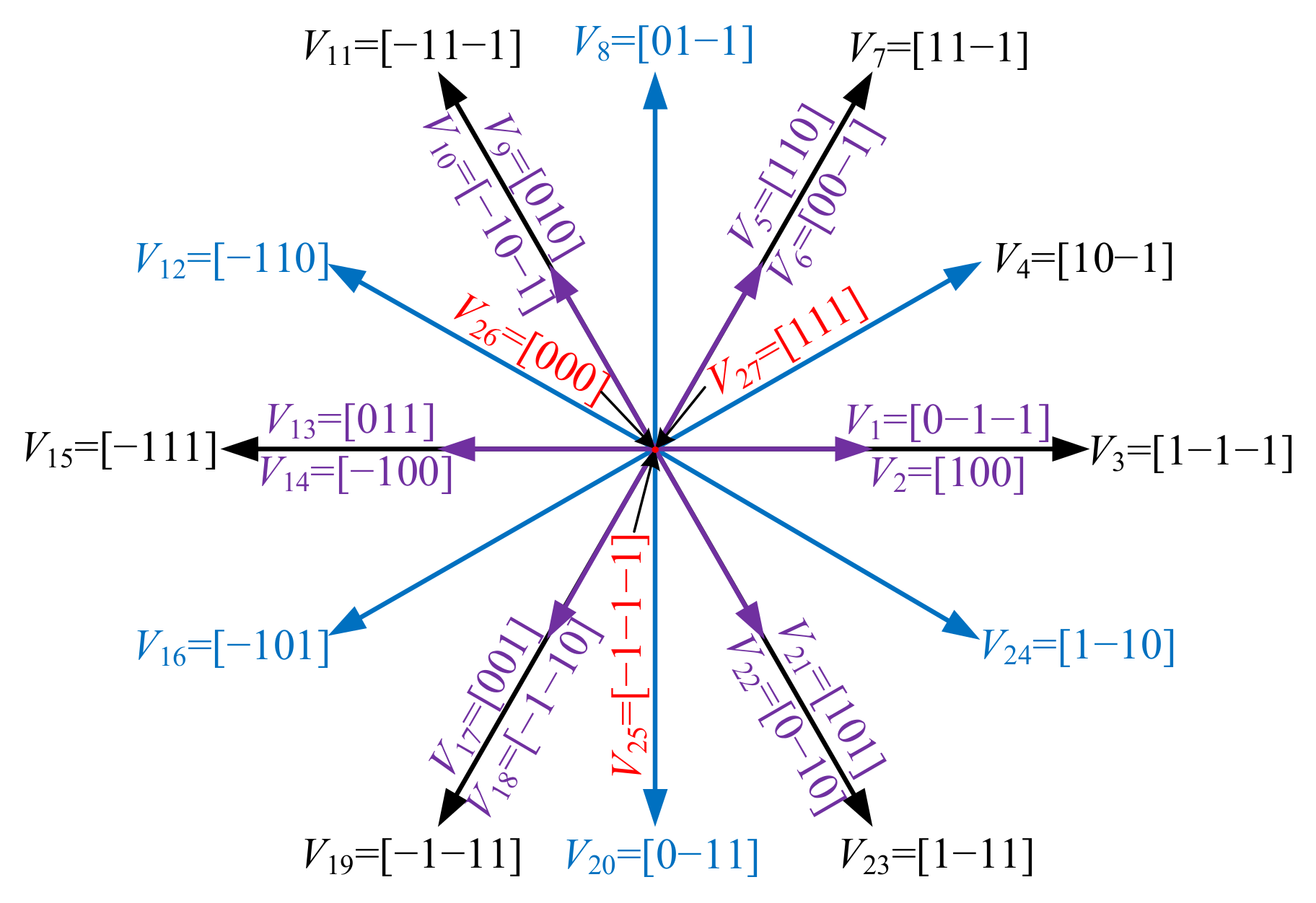
The simplified circuit topology of the 3L-NPC inverter is illustrated in Figure 1, where the output terminal is, respectively, linked to the positive-bus “P”, negative-bus “N”, or specifically linked to the neutral-point “O” via a diode-clamping circuit. In this way, the 3L-NPC inverter can theoretically produce three different voltage level outputs and 27 voltage vectors, as shown in Figure 2.

3. Control Algorithm

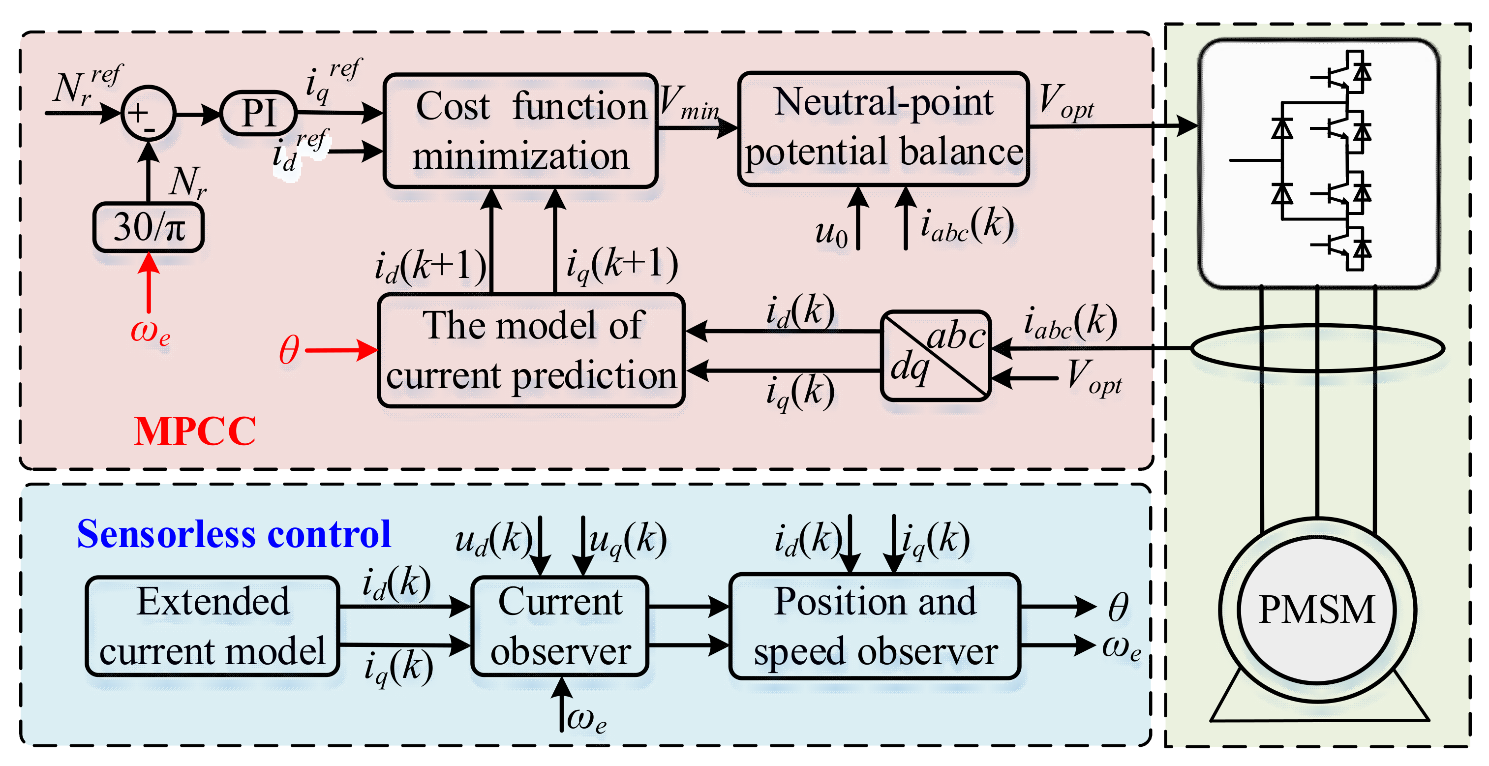
The overall diagram of the proposed sensorless control is depicted in Figure 3. The model predictive current control (MPCC) module in the proposed algorithm mainly requires the rotor position angle, reference current values, and predicted current values. The variants, which are difficult to measure, can be estimated through the suitably designed observer. In terms of the proposed sensorless drive, the rotor position angle is estimated from an estimated value of d–q-axes currents according to the calculated relationship between them. Then, the rotor speed information takes the place of the measured information feeding back to the model predictive controller.

3.1. MPCC

To effectively address the implicated operation constraints within the three-level inverter, the objective of the MPCC scheme is involved in the applied vector choosing and neutral-point voltage balance.
After transforming the stator voltage equation in (2), the differential equation of the d–q-axes current can be obtained as
d d t i d i q = R / L d ω e L q / L d ω e L d / L q R / L q i d i q + u d / L d u q ω e ψ f / L q  
The currents at the (k + 1)th, namely, [id(k + 1) and iq(k + 1)], are able to be predicted by utilizing the forward Euler discretization equation as
i d ( k + 1 ) i q ( k + 1 ) = 1 R T s / L d ω e T s L q / L d 1 R T s / L q ω e T s L d / L q i d ( k ) i q ( k ) + T s / L d 0 0 T s / L q u d ( k ) u q ( k ) + 0 ψ f ω e T s / L q
where Ts donates the sampling period; (k) and (k +1) represent the components measured at the (k)th and predicted at the (k + 1)th, respectively.
Specifically, at the (k)th sampling period, the stator voltages used in (3) can be calculated as
u d ( k ) u q ( k ) = cos θ sin θ sin θ cos θ u α ( k ) u β ( k )  
with
u α ( k ) u β ( k ) = 2 / 3 1 / 2 1 / 2 0 3 / 3 3 / 3 u a ( k ) u b ( k ) u c ( k )  
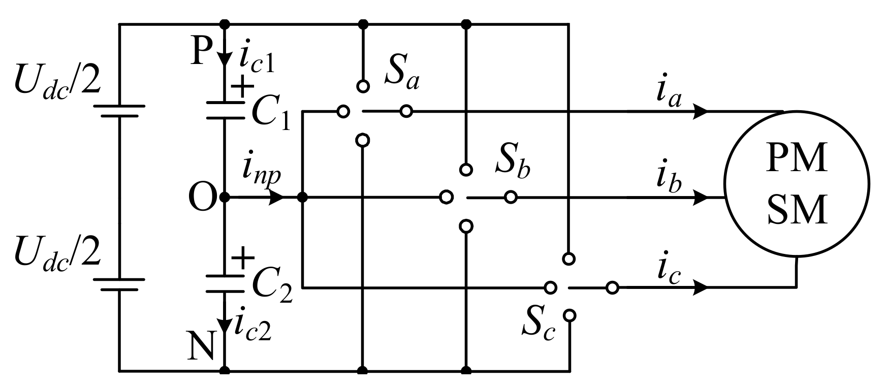
where ux(k) are the three-phase voltages at the (k)th sampling period, ux(k) = (Sx + 1) × Udc/2, x∈{a, b, c}, Udc is the dc-bus voltage, Sx refers to the switch states of the three-phase bridge arms, as can be seen in Figure 4, and Sx∈{−1, 0, 1}; uα(k) and uβ(k) represent the αβ-axes voltages, respectively; θ is rotor position angle.
Furthermore, the cost function, which combines the absolute errors between the commands and prediction values in terms of the stator current, can be constructed as
g = i d r e f ( k + 1 ) i d ( k + 1 ) + i q r e f ( k + 1 ) i q ( k + 1 )  
where idref(k + 1) and iqref(k + 1) are given as the d–q-axes current commands at the (k + 1)th. To keep balance between the two current errors, a weighting factor is not utilized in the cost function.

3.2. Neutral-Point Voltage Balance Control

It is important to note that if the NPV is unbalanced in the 3L-NPC inverter, several issues will limit its employment, such as current distortion, increased torque ripple, and even the serious damage of semiconductor devices. Therefore, this paper attempts to address the unbalanced NPV issue of a 3L-NPC inverter through the investigation of the relationships between various voltage vectors and the NPV.
Initially, the drive circuit of a 3L-NPC-inverter-fed PMSM can be equivalent to a simplified circuit model, as shown in Figure 4. Here, C1 and C2 donate the voltage-dividing capacitors, whose flowing currents are ic1 and ic2, respectively, and C1 = C2; ia, ib and ic represent the three-phase currents, and the sum of the all three is zero; inp is the neutral-point current; Sa, Sb and Sc correspond to the switch states of the simplified three-phase bridge arms, which can only be set as −1, 0, or 1 when the switch is connected to N, O, and P, respectively. Intrinsically, the reason for the unbalanced NPV is because the inp has failed to remain at 0A, in conjunction with the charge and discharge of the dc-bus capacitors. In addition, the neutral-point current inp can be expressed as
i n p = x = a , b , c ( 1 S x ) i x  
On the condition of Sx = −1 or Sx = 1, namely, 1−|Sx| = 0, inp with zero value has no effect on the neutral-point voltage. When Sx =0, namely, 1−|Sx| = 1, it is obvious that inp fails to remain at zero, resulting in the charge–discharge operation of C2. In this way, uneven partial pressure occurs between C1 and C2, indicating the problem of an unbalanced NPV.
Furthermore, the effects of different switching vectors on the NPV are shown in Table 1. The symbols “+”, “−”, and “=” indicate the states of the NPV in the following order: increase, decrease, and invariant. inp is decreased when employing medium vectors, and remains unchanged when employing large vectors and zero vectors, while the positive and negative redundant small vectors have opposite impacts on the neutral-point current. Additionally, each set of positive and negative redundant small vectors have the same magnitude and direction, indicating that their application leads to the same control effect on motor control. As such, when the Vmin outputting from the cost function is a small vector, the balance control of the NPV in the 3L-NPC inverter can be realized through replacing the positive and negative redundant small vectors. For example, if V1 = [0−1−1] is the applied vector to the inverter, inp will be equal to ia (assuming ia > 0); according to Equation (7), C2 will be discharged, leading to the decrease in the NPV. In this time, if the sampled neutral-point voltage U0 is less than zero, the counterpart of V1, namely V2 = [100], should be adopted, which causes C2 to be charged, and the NPV therefore increases.

3.3. Current Observer

In the proposed sensorless scheme, an electric angular velocity tracking error associated with the d–q-axes current tracking error is an important argument. Hence, in order to obtain the needed current tracking error, an estimated value rather than the measured value of the d–q-axes current should first be obtained.
In this case, an extended current model of the d–q-axes is adopted in the proposed scheme. According to (2), the differential equation of the d–q-axes current can be rewritten as
d d t i d + ψ f / L d i q = R / L d ω e L q / L d ω e L d / L q R / L q i d + ψ f / L d i q + 1 / L d 0 0 1 / L q u d + R ψ f / L d u q
with the definition as
i d i q u d u q = i d + ψ f / L d i q u d + R ψ f / L d u q  
Afterward, combining (8) and (9), the adjustable current model can be built as
d d t i d i q = R / L d ω e L q / L d ω e L d / L q R / L q i d i q + 1 / L d 0 0 1 / L q u d u q  
Then, the current observer could be designed to estimate the d–q-axes currents, as
d d t i ^ d i ^ q = R / L d ω ^ e L q / L d ω ^ e L d / L q R / L q i ^ d i ^ d + 1 / L d 0 0 1 / L q u ^ d u ^ q  
where hat “^” represents the estimated value; u ^ d = ud’, u ^ q = uq’, and it has been proved to be asymptotically stable in [19].
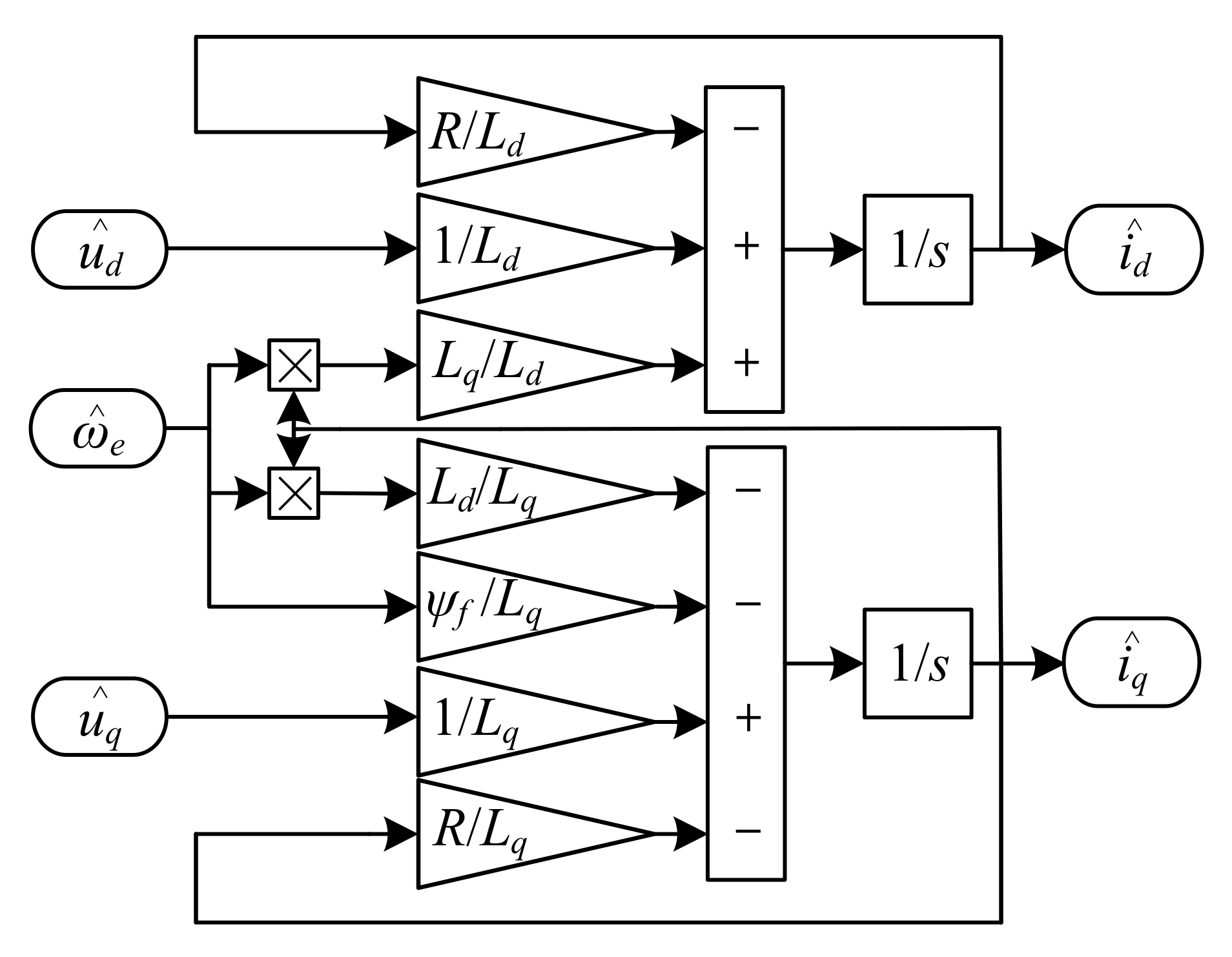
It is obvious that estimated values of the dq-axes currents can be obtained when ω ^ e , u ^ d , and u ^ q are all clear. As such, a current observer can be constructed according to the adjustable model of the dq-axes current, as shown in Figure 5, where ω ^ e , u ^ d , u ^ q are defined as the input value.

3.4. Rotor Position Observer

As mentioned previously, to further obtain rotor position information, the electric angular velocity tracking error should be calculated. As can be seen from (10) and (11), when i ^ d = id’ and i ^ q = iq’, ω ^ e will be equal to ωe. Therefore, if (11) is subtracted from (10), the existing observed current can be utilized to build the following mathematical model
d d t Δ i d Δ i q + R / L d 0 0 R / L q Δ i d Δ i q = L q / L d 0 0 L d / L q ω e i q ω ^ e i ^ q ω e i d ω ^ e i ^ d  
where Δid = id- i ^ d and Δiq = iq- i ^ q represent the tracking error of the d–q-axes current, respectively. Δωe = ωe ω ^ e , represents the electric angular velocity tracking error. Then, (12) can be transformed into
L d / L q 0 0 L q / L d d d t Δ i d Δ i q + R / L q 0 0 R / L d Δ i d Δ i q + ω e 0 0 ω e i q i ^ q i d i ^ d = Δ ω e i ^ q Δ ω e i ^ d  
According to the above analysis, the electric angular velocity tracking error Δωe can be directly calculated by the combined action from Δid and Δiq. Thus, (13) should be rewritten as
Δ ω e ( i ^ d + i ^ q ) = L d L q d Δ i d d t + ( R L q ω e ) Δ i d [ L q L d d Δ i q d t + ( R L d + ω e ) Δ i q ]  
Consequently, a d–q-axes current error PI controller mainly associated with the Δid and Δiq is constructed to obtain the electric angular velocity tracking error Δωe as
0 t Δ ω e = ( k i d s + k p d ) Δ i d ( k i q s + k p q ) Δ i q  
where kp and ki represent the proportional and integral coefficients of PI controllers, respectively. Thereafter, the angular velocity of the rotor can be estimated by
ω e ^ = k ω e 0 t Δ ω e  
where kωe is the proportionality coefficient of Δωe. In this way, once the two estimated currents reach the real currents, the rotor speed error will be around zero, and then the estimated rotor speed will be stable.
Lastly, the rotor position angle θ can be calculated by the integral operation of ω ^ e as
θ = 1 s ω ^ e  
Figure 6 shows the composition of the rotor position observer. It is observed that the position and speed information of the machine can be extracted from two PI controllers associated with the tracking errors of d–q-axes current.

3.5. Summary of the Proposed Method

With reference to the analysis above, a trial-and-error method can be carried out to obtain the suitable proportional and integral coefficients for acceptable performance, and the following steps are required to implement the proposed method:
  • Measure the stator currents, dc-link voltage, and the NPV;
  • Calculate the stator currents and voltages in the d–q-axes via coordinate transformation;
  • Estimate the d–q-axes current i ^ d , i ^ q via the designed current observer, as shown in Figure 5;
  • Obtain the estimated value of the electric angular velocity using (16), and then the rotor position angle θ can be calculated by (17);
  • Acquire iqref, the reference values of the q-axis current, via the PI controller of the speed error, and then set idref(k + 1) = idref, iqref(k + 1) = iqref;
  • Substitute the 27 switching states of the 3L-NPC inverter and the rotor position angle into (4) and (5) to calculate the d–q-axes voltages at the (k)th under a different voltage vector, and, at the same time, predict the stator current at the (k + 1)th;
  • Calculate and compare the cost function values under the different voltage by substituting the reference current values obtained in Step 5 and the predicted current values obtained in Step 6 to receive the optimal vector Vmin∈{V1, V2, ..., V27} satisfying min{g};
  • Judge whether the obtained vector is one of the small vectors. If not, apply the optimal vector to the inverter. Otherwise, perform the next step;
  • If inp × U0 ≥ 0, directly exert the corresponding small vector on the inverter; otherwise, adopt its redundant counterpart to drive the machine.
4. Results

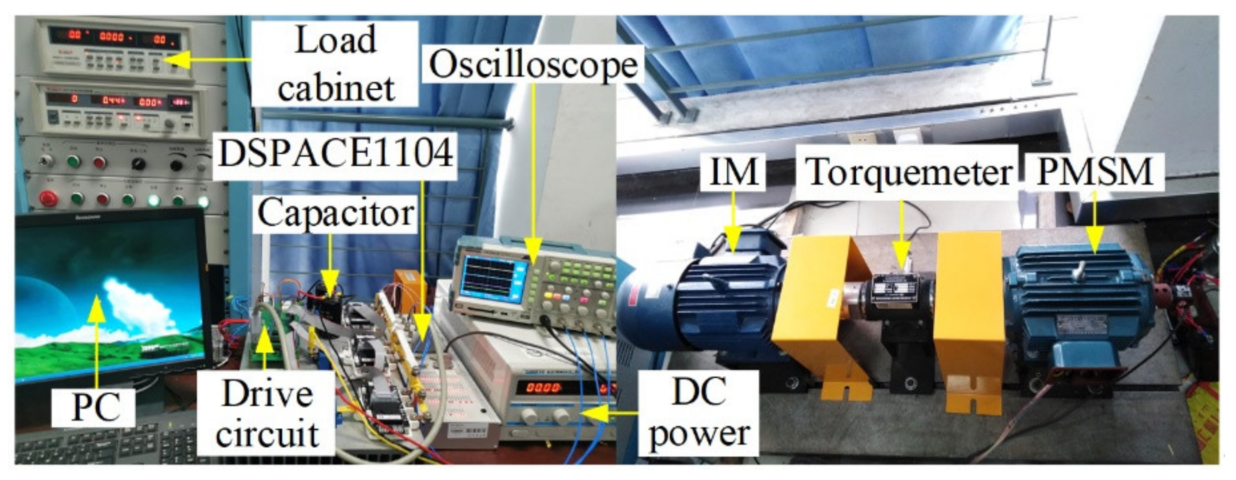
Aiming to validate the correctness of the proposed sensorless scheme for the MPCC, a 2.2 kW PMSM experimental prototype with 300 V dc-link voltage was employed in the test, as illustrated in Figure 7. All the parameters of the experimental machine are the same as the simulated setup, as listed in Table 2. A dSPACE1104 digital controller was applied for the real-time regulation via connecting to the S-function of Matlab/Simulink2009a with a PC, realizing the control system with a sampling period of 200 μs. Meanwhile, the drive circuit was considered as the connection module of software and hardware to realize the control of the PMSM by the software, including signal acquisition and transfer circuit, inverter drive circuit, 3L-NPC inverter module, and so on. Specifically, the 3L-NPC inverter module was derived from three F3L300R07PE4 IGBT modules from INFINEON with a maximum voltage stress of 650 V and a current flow of 600 A, and each module consisted of four IGBT switches and two diodes for clamping purposes. The F3L300R07PE4 modules were equipped with the proven PSPC 432-EP4 driver, which could open/close each IGBT switch in isolation. The snubber circuit in the PSPC 432-EP4 was designed simply as a single capacitor type, with a capacitance of 470 pF. Additionally, phase current and capacitor voltage were measured by current sensors HAS50S and voltage transducers LV25-P, respectively.

4.1. Steady-State Performance

With the aim to evaluate the operating performance generated by the proposed sensorless scheme at the steady-state, experiments were carried out under the circumstances that the speed command was set as 50 rpm and 500 rpm, as exhibited in Figure 8a,b, respectively. In these two cases, the torque command was given as 6 N∙m. It can be observed that both speed and torque can remain steady around the given value as expected in the two cases, and the scheme yields a sinusoidal stator current with THD values of about 14.22% and 11.46%, respectively.
Furthermore, experimental waveforms considering the NPV balance are displayed in Figure 9. Certainly, both phase-A current and the rotor position angle are severely distorted, and the NPV increases to approximately 200 V before the control strategy is introduced. In particular, the motor speed produces large oscillations so that the whole system is out of control. Comparatively, speed can remain steady around 500 rpm, and the phase-A current changes into a nearly sinusoidal waveform once the NPV balance control is involved. In the meantime, the NPV returns quickly to 0 V within 200 ms, which is in accordance with the theoretical analysis. Overall, the proposed sensorless scheme gives an advantageous performance in terms of the neutral-point voltage balance.
Next, to clearly analyze the position-tracking performance of the proposed scheme, the speed tracking error and position tracking error are introduced by
e N r = ( N r r e a l N r ) / N r r e f × 100 % e θ = ( θ r e a l θ ) / 2 π × 100 %
where Nrreal and θreal represent the actual rotor speed and the actual position angle, respectively.
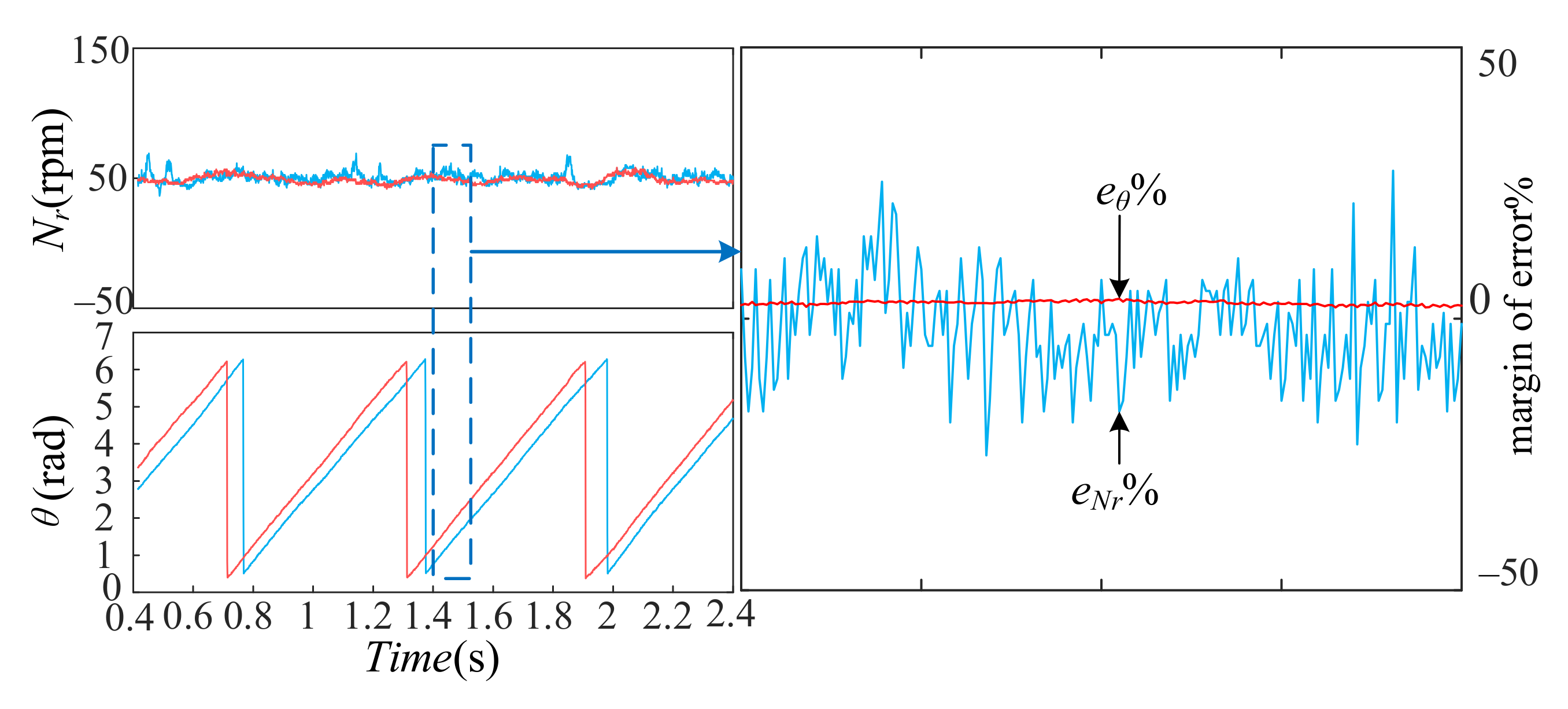
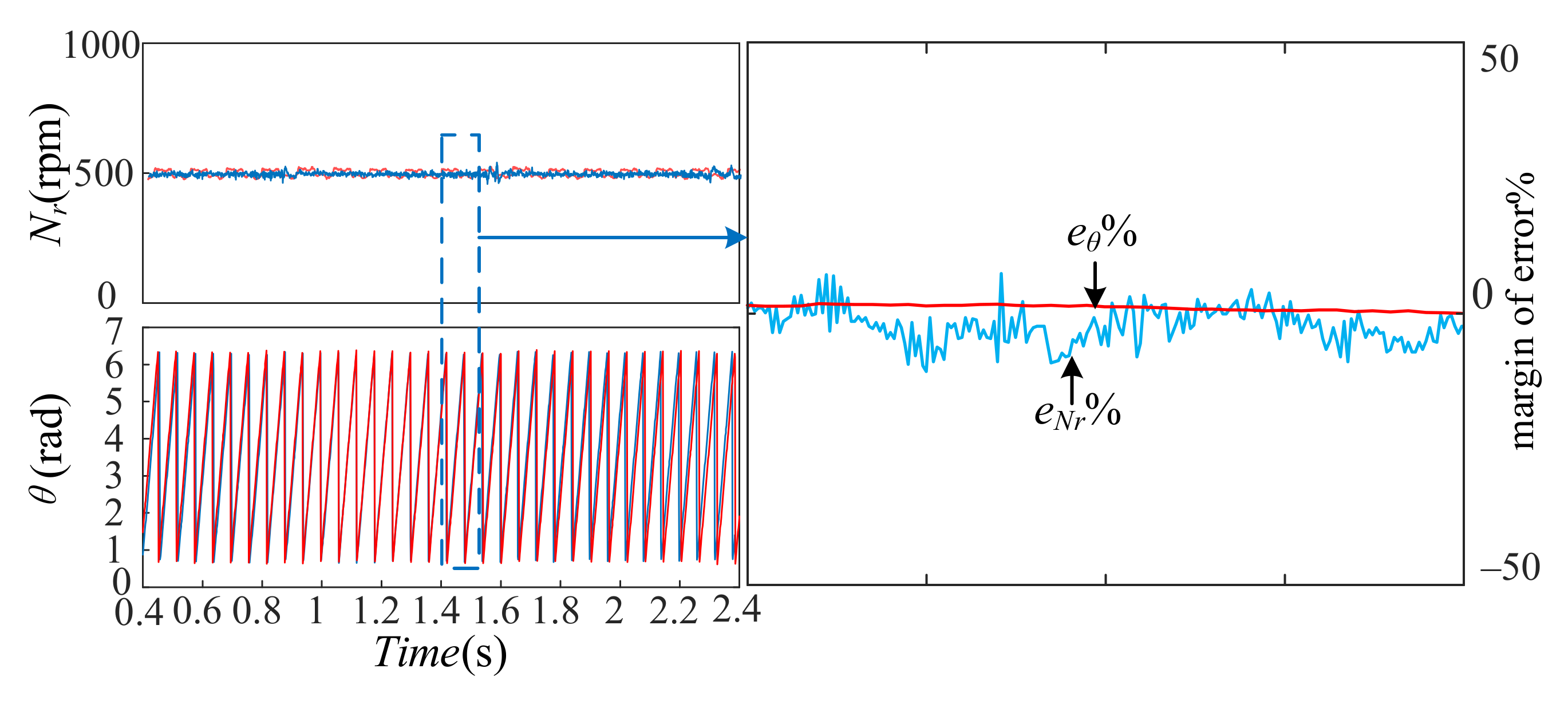
Specifically, the position-tracking performance is tested under the two cases in Figure 8, as presented in Figure 10 and Figure 11. It is worthwhile highlighting that the estimated value of the rotor speed follows the actual value accurately, not only under the condition that the speed command is set at 50 rpm but also when it is set at 500 rpm. In detail, the maximum speed tracking error at 50 rpm is within 25%; meanwhile, the maximum speed tracking error is within 10% at 500 rpm. On the other hand, the position-tracking error eθ of both operating conditions is no more than 5%, indicating that the proposed sensorless scheme satisfactorily reflects the position-tracking performance.

4.2. Dynamic Performance

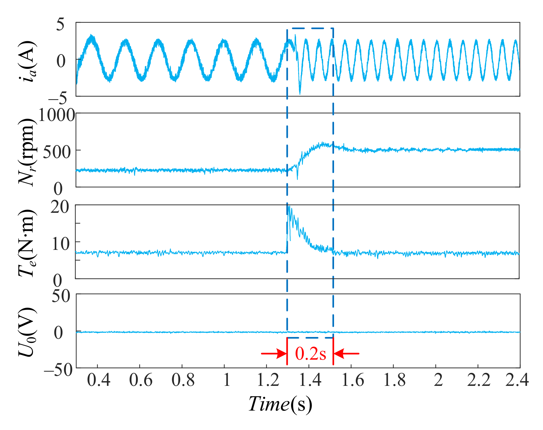
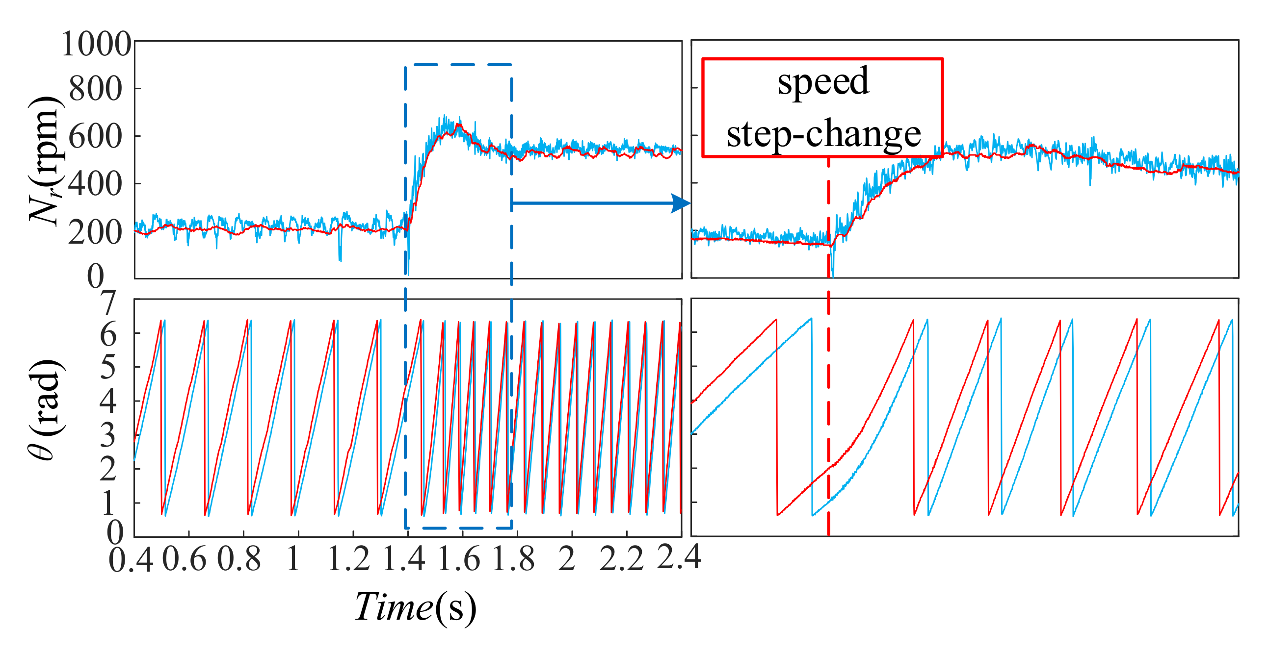
Two tests were executed to attest that the proposed sensorless scheme exhibits the accepted dynamic performance. In Figure 12, the acceleration operation is performed by abruptly transforming the speed command from 200 to 500 rpm, with the torque command being 6 N∙m. The result is smooth speed profiles with negligible overshoot, with the whole response being accomplished within roughly 200 ms. Additionally, the electromagnetic torque is capable of tracking the load command immediately, and the NPV remains constant around 0 V in the whole dynamic process of speed change. Additionally, Figure 13 exhibits the experimental waveforms of the speed-tracking response and the position tracking response of the corresponding speed step-change test. As illustrated in the figure, the estimated speed follows the actual speed accurately during the speed step-change, and position observations can also quickly respond to changes in the speed and accurately track the actual position of the motor.
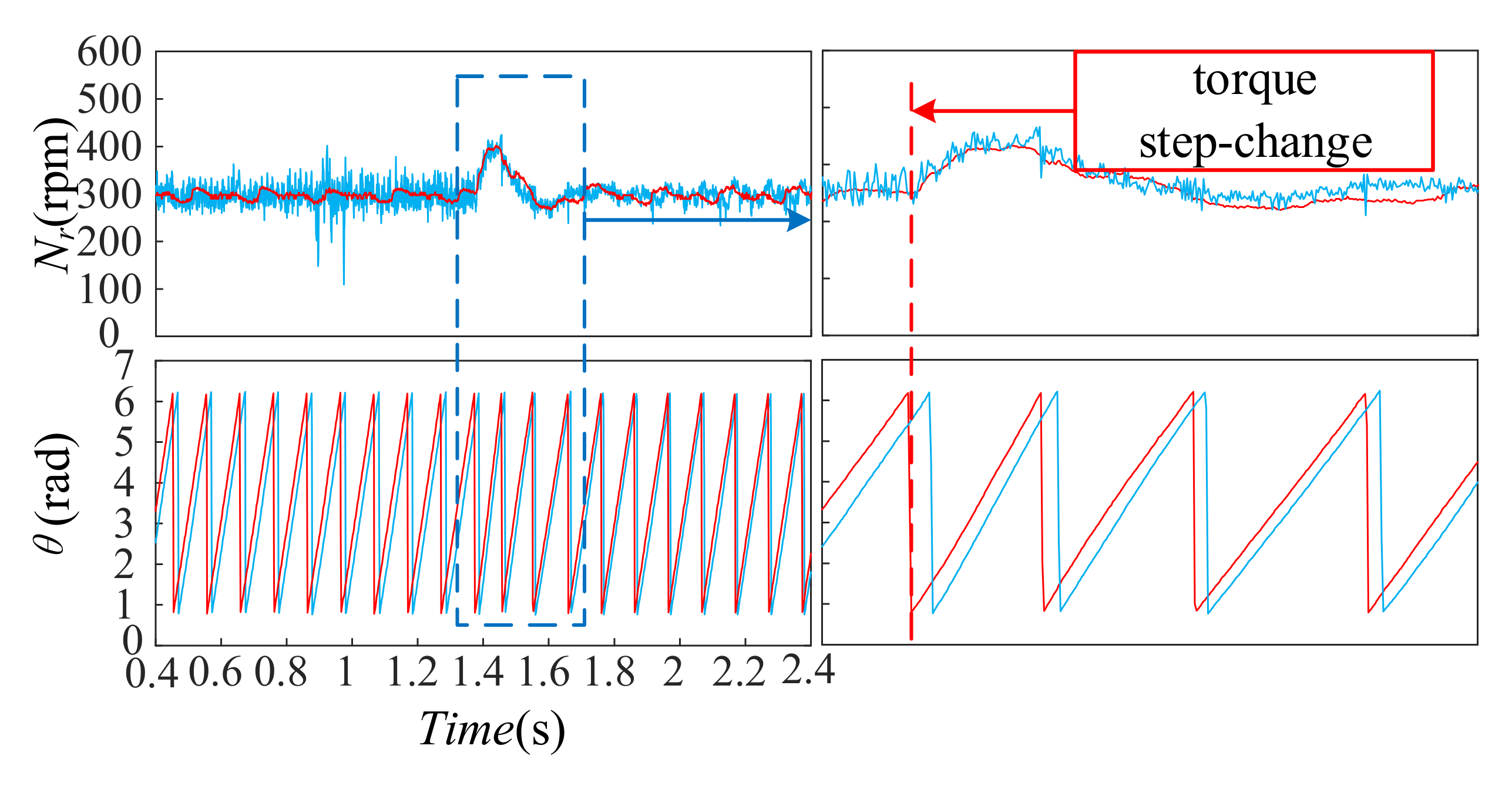
In addition, the torque step-change test is executed at 300 rpm, as shown in Figure 14. It can be observed that the response torque step-change is completed within 200 ms, where the torque is abruptly decreased from 6 N∙m to 0 N∙m. The neutral-point voltage can be kept as a constant value of 0 V during the entire transient process, while the phase-A current and speed are all regulated to follow the load change in view of a negligible overshoot of speed occurring in the process of the load step-change. Meanwhile, a dynamic tracking waveform of speed and rotor position at the torque step-change is exhibited in Figure 15. It is worthwhile noting that both speed-tracking performance and position-tracking performance are acceptable and remain unchanged in the process of the torque step-change. Although the high-frequency oscillations (and even some spikes) in the feedback signal may directly result in the output of controller performance at the same oscillations, on the whole, the proposed sensorless scheme can obtain an acceptable quick dynamic response performance.

5. Conclusions

In this article, a speed-sensorless MPCC for the PMSM drive supplied by a 3L-NPC inverter is proposed, which can operate the PMSM drive in the full speed domain and is not limited by the types of the inverter and method used. Different from the well-known sensorless methods, namely, the BEMF-based scheme and the magnetic saliency-based scheme, this paper builds a current observer on the premise of an adjustable current model and focuses on extracting the position and speed information from two PI controllers associated with the tracking errors of d–q-axes current. Both the speed-tracking performance and the position-tracking performance in experimental tests are acceptable under high-speed and low-speed conditions. Nonetheless, at present, the MPCC used in this paper takes some demerits, including the higher computation burden and lower current tracking performance. Luckily, with the progress of microprocessor technology, the advanced DSP platforms alongside FPGA systems are a promising solution to enhance the competitiveness of the proposed method in a practical application.

Author Contributions

Conceptualization, C.Z. (Chenhui Zhou) and C.Z. (Chenguang Zhu); methodology, C.Z. (Chenguang Zhu); software, C.Z. (Chenguang Zhu); validation, C.Z. (Chenhui Zhou) and C.Z. (Chenguang Zhu); formal analysis, C.Z. (Chenhui Zhou); investigation, C.Z. (Chenhui Zhou); resources, F.Y.; data curation, C.Z. (Chenhui Zhou); writing—original draft preparation, C.Z. (Chenguang Zhu); writing—review and editing, C.Z. (Chenhui Zhou); visualization, C.Z. (Chenhui Zhou); supervision, F.Y. and J.M.; project administration, F.Y.; funding acquisition, F.Y. and J.M. All authors have read and agreed to the published version of the manuscript.

Funding

This research was funded by the Postgraduate Research & Practice Innovation Program of Jiangsu Province, China, grant number KYCX21_3089, and the Key People’s Livelihood Science and Technology Project of Nantong City, grant number MS22020022.

Institutional Review Board Statement

Not applicable.

Informed Consent Statement

Not applicable.

Data Availability Statement

Not applicable.

Conflicts of Interest

The authors declare no conflict of interest.

References

  1. Kelm, P.; Mieński, R.; Wasiak, I. Energy Management in a Prosumer Installation Using Hybrid Systems Combining EV and Stationary Storages and Renewable Power Sources. Appl. Sci. 2021, 11, 5003. [Google Scholar] [CrossRef]
  2. Cheng, H.; Chen, H.; Yang, Z.; Huang, W. Braking Torque Closed-Loop Control of Switched Reluctance Machines for Electric Vehicles. J. Power Electron. 2015, 15, 469–478. [Google Scholar] [CrossRef] [Green Version]
  3. Zhou, J.; Liu, K.; Li, J. VSI Nonlinearity Compensation of a PMSM Drive System Using Deadbeat Prediction Based Current Zero-Crossing Detection. World Electric Vehicle J. 2021, 12, 17. [Google Scholar] [CrossRef]
  4. Chen, W.; Zeng, S.; Zhang, G. A Modified Double Vectors Model Predictive Torque Control of Permanent Magnet Synchronous Motor. IEEE Trans. Power Electron. 2019, 34, 11419–11428. [Google Scholar] [CrossRef]
  5. Liu, C. Emerging Electric Machines and Drives—An Overview. IEEE Trans. Energy Conversion 2018, 33, 2270–2280. [Google Scholar] [CrossRef]
  6. Payami, S.; Behera, R.K. An Improved DTC Technique for Low-Speed Operation of a Five-Phase Induction Motor. IEEE Trans. Ind. Electron. 2017, 64, 3513–3523. [Google Scholar] [CrossRef]
  7. Shukla, S.; Sreejeth, M.; Singh, M. Minimization of Ripples in Stator Current and Torque of PMSM Drive Using Advanced Predictive Current Controller Based on Deadbeat Control Theory. J. Power Electron. 2021, 21, 142–152. [Google Scholar] [CrossRef]
  8. Luo, Y.; Liu, C. Elimination of Harmonic Currents Using a Reference Voltage Vector Based-Model Predictive Control for A Six-Phase PMSM Motor. IEEE Trans. Power Electron. 2019, 34, 6960–6972. [Google Scholar] [CrossRef]
  9. Luo, Y.; Liu, C. A Simplified Model Predictive Control for A Dual Three-Phase PMSM with Reduced Harmonic Currents. IEEE Trans. Ind. Electron. 2018, 65, 9079–9089. [Google Scholar] [CrossRef]
  10. Gong, Z.; Dai, P.; Wu, X.; Deng, F. A Hierarchical Model Predictive Voltage control for NPC/H-Bridge Converters with A Reduced Computational Burden. J. Power Electron. 2017, 17, 136–148. [Google Scholar] [CrossRef] [Green Version]
  11. Jun, E.-S.; Nguyen, M.H.; Kwak, S. Model Predictive Control Method Based on Deterministic Reference Voltage for Single-Phase Three-Level NPC Converters. Appl. Sci. 2020, 10, 8840. [Google Scholar] [CrossRef]
  12. Calle-Prado, A.; Alepuz, S.; Bordonau, J. Model Predictive Current Control of Grid-Connected Neutral-Point-Clamped Converters to Meet Low-Voltage Ride-Through Requirements. IEEE Trans. Ind. Electron. 2015, 62, 1503–1514. [Google Scholar] [CrossRef] [Green Version]
  13. Zhao, H.; Li, Y.; Lin, F.; Yan, Y. Neutral-Point Voltage Balance Control of Three-Level Converter Based on Selection Method of Dynamical Adjustment for Small Voltage Vector. Appl. Sci. 2021, 11, 5076. [Google Scholar] [CrossRef]
  14. Kakosimos, P.; Abu-Rub, H. Deadbeat Predictive Control for PMSM Drives with 3-L NPC Inverter Accounting for Saturation Effects. IEEE J. Emerg. Sel. Top. Power Electron. 2018, 6, 1671–1680. [Google Scholar] [CrossRef]
  15. Im, J.; Kim, R. Improved Saliency-Based Position Sensorless Control of Interior Permanent-Magnet Synchronous Machines with Single DC-Link Current Sensor Using Current Prediction Method. IEEE Trans. Ind. Electron. 2018, 65, 5335–5343. [Google Scholar] [CrossRef]
  16. Tang, Q.; Shen, A.; Luo, P. IPMSMs Sensorless MTPA Control Based on Virtual q-Axis Inductance by Using Virtual High-Frequency Signal Injection. IEEE Trans. Ind. Electron. 2020, 67, 136–146. [Google Scholar] [CrossRef]
  17. Xiao, D.; Nalakath, S.; Filho, S. Universal Full-Speed Sensorless Control Scheme for Interior Permanent Magnet Synchronous Motors. IEEE Trans. Power Electron. 2021, 36, 4723–4737. [Google Scholar] [CrossRef]
  18. Jofre, M.; Llor, A.; Silva, C. Sensorless Low Switching Frequency Explicit Model Predictive Control of Induction Machines Fed by Neutral Point Clamped Inverter. IEEE Trans. Ind. Electron. 2019, 66, 9122–9128. [Google Scholar] [CrossRef]
  19. Quntao, A.; Li, S. On-line Parameter Identification for Vector Controlled PMSM Drives Using Adaptive Algorithm. In Proceedings of the 2008 IEEE Vehicle Power and Propulsion Conference, Harbin, China, 3–5 September 2008; pp. 1–6. [Google Scholar]
Figure 1. The main circuit of a three-level inverter.
Applsci 11 10840 g001
Figure 2. Space vector distribution of a 3L-NPC inverter.
Applsci 11 10840 g002
Figure 3. A diagram of the proposed sensorless control algorithm.
Applsci 11 10840 g003
Figure 4. An equivalent circuit model of the 3L-NPC inverter-fed PMSM.
Applsci 11 10840 g004
Figure 5. A diagram of the current observer of the d–q-axes.
Applsci 11 10840 g005
Figure 6. Diagram of the position observer of the rotor.
Applsci 11 10840 g006
Figure 7. Experimental setup.
Applsci 11 10840 g007
Figure 8. Experimental results in a steady-state with a 6 N∙m torque command: (a) 50 rpm speed command; (b) 500 rpm speed command.
Applsci 11 10840 g008
Figure 9. Experimental results of the NPV balance control.
Applsci 11 10840 g009
Figure 10. Tracking performances of speed and position under a speed command of 50 rpm (the red line represents the actual value, and the blue line represents the estimated value).
Applsci 11 10840 g010
Figure 11. Tracking performances of speed and position under a speed command of 500 rpm (the red line represents the actual value, and the blue line represents the estimated value).
Applsci 11 10840 g011
Figure 12. Dynamic experimental results during the speed step-change.
Applsci 11 10840 g012
Figure 13. Tracking performances of speed and position during the speed step-change (the red line represents the actual value, and the blue line represents the estimated value).
Applsci 11 10840 g013
Figure 14. Dynamic experimental results during the torque step-change.
Applsci 11 10840 g014
Figure 15. Tracking performances of speed and position during the torque step-change (the red line represents the actual value, and the blue line represents the estimated value).
Applsci 11 10840 g015
Table 1. The effects of different switching vectors on the NPV.
Positive Small VectorU0Negative Small VectorU0Medium VectorU0Large VectorU0Zero VectorU0
100+0−1−110−11−1−1=111=
110+00−101−111−1=000=
010+−10−1−110−11−1=−1−1−1=
011+−100−101−111=
001+−1−100−11−1−11=
101+0−101−101−11=
Table 2. Motor parameters.
ItemsSpecifications
Rated power2.2 kW
Rated current5 A
Rated voltage380 V
Rated torque14 N∙m
Direct axis inductance24 mH
Quadrature axis inductance36 mH
Stator resistance5.25 Ω
Rated speed1500 rpm
Moment of inertia0.001 kg.m2
Pole pairs2
Permanent magnet flux linkage0.8 Wb
Publisher’s Note: MDPI stays neutral with regard to jurisdictional claims in published maps and institutional affiliations.