Featured Application
The most commonly used methods for line detection in images are the Radon and Hough transforms. For a line to be detected, many pixels of the image must be aligned on the slope and offset values of the line, in such a way that lines that do not run through the whole domain, because they are cornered, usually get few votes and do not pass the detection threshold. However, the conventional Radon transform puts a lot of effort into accurately calculating the corner lines, since, without this information, the transform is not invertible. However, for detection, the proposed central transform is much more efficient, since ignoring about 15% of corner values results in a 50% reduction of the computation. If invertibility is a requirement, we propose the periodic transform, which exhibits a similar reduction of computations.
Abstract
The multi-scale discrete Radon transform (DRT) calculates, with linearithmic complexity, the summation of pixels, through a set of discrete lines, covering all possible slopes and intercepts in an image, exclusively with integer arithmetic operations. An inversion algorithm exists and is exact and fast, in spite of being iterative. In this work, the DRT forward and backward pair is evolved to propose two faster algorithms: central DRT, which computes only the central portion of intercepts; and periodic DRT, which computes the line integrals on the periodic extension of the input. Both have an output of size , instead of , as in the original algorithm. Periodic DRT is proven to have a fast inversion, whereas central DRT does not. An interesting application of periodic DRT is its use as building a block of discrete curvelet transform. Central DRT can provide almost a speedup over conventional DRT, probably becoming the faster Radon transform algorithm available, at the cost of ignoring 15% of the summations in the corners.
1. Introduction
1.1. Radon Transform, Use, and Algorithms for Its Computation
The Radon transform, as originally envisioned [1], describes a bi-dimensional function, in terms of the set of line integrals through its domain. A set of line integrals that is complete, in the sense of covering all possible angles and interceptions. This mathematical tool has had an enormous impact in radiology, as it made tomography of the human body viable [2,3]. This is because, as a pair of transforms, it manages not only to describe the integrals from the values in the measurement domain, but also to recover the values, based on their line integrals. Those are the forward and backward Radon transforms, respectively. In tomography, the most relevant part is the inverse path: the backward transform that reconstructs the values (the absorption rate of the different tissues within the human body) from the line integrals (the measured energy of beams attenuated after they traversed the body).
In order to cope with Radon transform in a computer, several methods have been proposed. The inverse transform is a hard problem, not only because of its ill-posed nature, but even the forward one can be tricky, as its computational complexity, with a brute force approach, is , because an integral must be calculated for each slope and for each intercept; additionally, each integral involves the many elements present in the path of that line. Fortunately there are better algorithms than brute force, and they bring the complexity down to .
Although the calculation of the forward transform can be uninspiring for tomography (that is the task of the computer tomography scanner), it can still be of interest, nowadays, in other fields. It can be used to aid in robot auto-positioning [4], as a biometric identifier [5], to speed up differential equations solvers [6], or to straighten pictures taken with mobile phones [7], to name but a few examples.
There are as many possible uses as there are methods to calculate the Radon transform. Some methods arose because of and for tomography; that is, with an emphasis on the inverse path. Among them are the algebraic reconstruction techniques [8], which are very tightly coupled to the design of the scanner. Another family of algorithms, probably the most widespread, arises from the Fourier projection-slice theorem [9,10]. This theorem allows Radon transforms to be expressed in terms of Fourier transforms; in doing so, the backward Radon transform is not only feasible, but inherits the computational complexity of the latter, becoming fast to compute. Moreover, after years of refinement, Fourier-based methods are virtually free of artifacts.
There are also methods designed specifically for the analysis of lines in images, i.e., with the emphasis on the forward transform. These are methods whose inputs will be intensities on a Cartesian grid. Although Fourier-based methods are still applicable, and despite their reduced complexity (of ), they are not the most optimal. There are methods, such as the Hough transform [11,12], with voting bins, which may be more efficient. Another family of methods relies on Dirac lattices and lines of rational slope [13,14] which can be also of interest, for example, for reconstructions with just a few projections [15].
Finally, we will consider a family of methods, which we will call multi-scale, that compute the forward transform with a divide-and-conquer approach, and so they exhibit the same complexity as those based on Fourier, , but without requiring interpolation or the use of floating point numbers. When they were initially proposed, they were not considered invertible, but it was later shown that such methods, although operating on integer mathematics, had a fast and exact inverse [16].
Our work is motivated by trying to squeeze the maximum computational efficiency out of the multi-scale DRT transform, in pursuit of its application, at video acquisition rates, in computer vision problems. We will demonstrate its applicability in two problems, but it could be advantageous in any context where a fast response is required, such as those mentioned in this introduction [4,5,6,7]. After this preamble, let us begin by explaining the multi-scale methods.
1.2. Conventional Discrete Radon Transform
Discrete Radon transform (DRT), with a multi-scale approach, dates back to the late 1990s [17,18,19] and was originally designed to compute all of the integrals (i.e., sums) of pixels located on a discrete line (actually a 1 pixel wide, N pixels long, stripe with approximately constant slope) that touches at least one point on an image, whose size is , whilst projecting in a semi-circumference around it. There exists an algorithm that solves this problem with linearithmic complexity (), for a quadrant covering from 0 to 45 degrees. By joining together four runs of the algorithm on four mirrored versions of the input, a sort of Möbius band is obtained, which comprises of the whole set of line integrals that arise when projecting on 180 degrees around the image: a discrete version of the sinogram in the continuum, devised by Johann Radon [1,3].
Suppose an image of size , N results are obtained by adding together the values in the same rows. Additionally, other N results are obtained by summing the values lying in the same columns. These two sets of summations correspond with projections at 0 and 90 degrees, respectively. Each summation adds N values and each set of summations comprises of N sums, corresponding to different intercepts in the projection axis. Two sums have been computed, in order to obtain line integrals. With a little more computational effort, the multi-scale DRT algorithm provides N sets of line integrals to different angles between 0 and 45 degrees and, for each angle, its whole set of intercepts.
Taking into account all the discrete lines that touch an image for a given projection angle is a non-trivial task. In order to not discard any line, even if it touches the image in just a single pixel, more intercepts must be considered for angles close to odd multiples of and less for those close to , and so forth. This explains why conventional DRT can have between N and number of intercepts, depending on the angle being calculated. Conventional DRT computes them all, and, as a result, the total output size for an input occupies , where only half of the results sum other than zero.
In this work, two alternatives are presented. They generate an output of size N along the intercept dimension, independent of the angle being considered; that is, the output size for a single quadrant will be the same as the input. This will alleviate the computations and memory footprint of DRT by almost half.
Considering the Figure 1, the first three subfigures, from left to right, show the same image but sheared, so that, when summed along rows, they give the conventional DRT for slopes 0 and 1 as results. There is a column at the left of each subfigure that is precisely the DRT at each intercept for that slope. It can be appreciated that the number of intercepts to be calculated can be as much as twice the vertical size of the input, in order to accommodate the most extreme intercepts, when slope is maximal. This is what gives rise to the particular shape of the conventional DRT output, as shown to the rightmost in Figure 1.
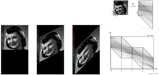
Figure 1.
First three subfigures: from left to right, an image sheared to accommodate, in a row, the discrete lines of conventional DRT for minimal, intermediate, and maximal slope of the 0 to 45 degrees quadrant. Rightmost, a depiction of input and output of conventional DRT for a single quadrant. Additionally, the shape of the output of 4 quadrants, joined together within a rectangular memory footprint, where half of the space is wasted.
The algorithm itself does not shear the images. Instead, it can be thought that a plurality of discrete lines will be traversed, summing the pixels that lie on them. For the 0 to 45 degrees quadrant, the relation between the pixels belonging to the same discrete line is formulated, based on the ascents on the vertical dimension while the horizontal dimension is traversed. A discrete line will visit exactly one pixel on each column, and no interpolation will be required. In this basic quadrant, the lines to be considered are the discrete versions of lines of the form , where s denotes the slope or ascent and d denotes the displacement or intercept. The variety of names is due to the adoption of the algebraic slope–intercept formulation of the lines and, simultaneously, the adherence to previous authors’ notations. Actually, in the context of discrete lines, it is more precise to denominate ascent, the parameter normally denoted as s. Anyway, from that s parameter, the slope could be calculated as and the angle of projection, relative to the positive direction of the x-axis, as . From now on, the parameters on the Radon domain will be denoted as s and d and called slope and displacement.
The slopes to be evaluated are those that generate ascents varying from 0 to pixels on the vertical axis, whilst traversing N pixels on the horizontal axis. For each slope, there will be as much as displacements to be calculated. In case of the slope being maximum, all the displacements are different from zero, whilst, when slope is minimal, only N displacements will really touch the image. This can be better appreciated in Figure 2.
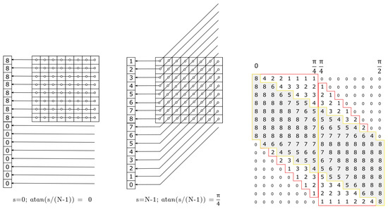
Figure 2.
Number of pixels to be summed together at different displacements, when calculating DRT for (left) and (middle). The number of pixels evaluated for the rest of slopes and displacements of two quadrants of a image are shown on the right.
These new algorithms have a goal to suppress the computations for the output at marginal displacements and, by doing so, the shape of the new DRTs output for the 4 quadrants will become a fully populated rectangle. In other words, the number of displacements considered for a single quadrant will be always N, independent of the slope.
Two alternative algorithms, with different uses and properties that overcome the aforementioned problem, have been developed, while still remaining of linearithmic complexity.
The equivalent shearing for different slopes, shown in Figure 1, for conventional DRT is now shown for central DRT in Figure 3. The idea behind central DRT is to exclusively compute the N displacements around the projection of the center of the image. Therefore, the output of central DRT should be coincident with a portion (the central band on a light gray color on Figure 2 surrounded by yellow) of the output of the conventional DRT (surrounded by red). It can be seen that most of the input, when sheared and truncated to the central N displacements, will still be considered. In Figure 2, the values inside the red area, but outside the yellow area, those that are going to be discarded, are less than a 15% of the total. It will be demonstrated that this can be achieved with a saving of almost half of the computations and, in certain scenarios, this central band can substitute the whole output of the conventional DRT. The proposed transform will save computations in the forward transform; although the backward transform exists and converges, it will be much slower than the backward transform of conventional DRT, becoming practically unusable.

Figure 3.
From left to right, an image sheared to accommodate, in a row, the discrete lines of central DRT for minimal, intermediate, and maximal slope of the 0 to 45 degrees quadrant.
1.3. Founding Idea on Periodic DRT
The second alternative transform that will be proposed will also have a reduced output size and a lesser number of computations, compared to conventional DRT. However, there will now also exist a fast backward transform; its output will, mostly, not be coincident with any portion of the conventional DRT. As can be noticed in Figure 4, the periodic DRT will operate as if the input image has been extended by periodicity. This type of transform was already known for non-multi-scale Radon methods [20], as Fourier-based methods operate on the periodic extension of the input. It will be coincident with conventional (and central) DRT for certain slopes and displacements, but in most cases, it will add replicas of the input, where the other multi-scale DRTs would add zeroes.

Figure 4.
From left to right, an image, sheared to accommodate, in a row, the discrete lines of central DRT for minimal, intermediate, and maximal slope of the 0 to 45 degrees quadrant.
1.4. Structure of this Paper
First, a deeper insight of the multi-scale approach to the discrete Radon transform is given. Then, the central variation of DRT will be introduced in Section 3 and the periodic DRT in Section 4. After that, these two proposals will be compared to conventional DRT and Radon transform algorithms based on Fourier projection-slice theorem in Section 5. This comparison will include some insight about the invertibility of each transform.
Central and periodic transform can act, under certain restrictions, as replacements for conventional DRT. A use and obtained speedup of the demonstrative application, running on a smart-phone, will be presented in Section 6 and the founding transform of first generation Curvelets, in the context of the shape-from-focus method, in Section 7.
To conclude the paper, some future lines will be outlined in Section 8.
2. Conventional 2D Discrete Radon Transform
In the continuum, the 2D Radon transform allows us to describe a 2D signal (), in terms of the integrals along lines parameterized by an angle and a displacement (), instead of single values, accessed by their horizontal and vertical pair of cartesian coordinates (). This is:
or, equivalently, using the absolute slope and displacement form, with :
The calculation of the Radon transform on a computer has to deal with the discretization of data. Basically, for regularly spaced discrete data, they will be available only for a finite number of samples, normally accessed with integer indexes. The problem arises when the continuous definition of line integral makes it necessary to evaluate the function at positions where there is no sample available and interpolation is required.
However, using the pseudo-polar Fourier transform [10] (a variation of FFT that operates on a grid of concentric squares), a discrete Radon transform can be designed that is algebraically exact, invertible, fast [21], and can be generalized to 3D [22,23]. However, it is based on Fourier transforms, which is something that we want to avoid. Moreover, if, as it is the case in our application domains, the problem to solve is purely discrete, the multi-scale Radon transform performs better than any other discrete Radon transform [24], including those based on pseudo-polar FFT.
2.1. Forward Multi-Scale Discrete Radon Transform
Götz & Druckmüller [17], Brady [18], and Brandt & Dym [19] almost simultaneously proposed a divide and conquer approach reminiscent to FFT, in the sense that it works by solving the problem at smaller scales and then combines those solutions to solve at greater scales, but with no multiplications nor complex twiddle factors involved, relying exclusively on integer arithmetics to achieve its goal. By working at multiple scales, and due to the symmetry of the problem, intermediate computations can be reused, preventing any sum to be computed twice, thus reducing the computational load from O() to O().
To make this possible, the key is to define a loose discrete line that traverses the domain, visiting only integer positions, and, therefore, not exactly in a straight way. Ascensions are defined recursively, making lines composed of two halves, which, in turn, each come from other two line segments of half their size (and so on) until line segments that join only two points are reached, and the problem can not be further reduced.
DRT authors eluded to establish any sort of trigonometric relation between the x and y variables; instead, they decomposed the u and s variables of Equation (2) into binary indexes and mixed them at the binary level, one index of u and s at a time, thus avoiding the direct multiplication of u by a slope, which would have produced non-integer indexes.
In a previous work [25], the formulation of DRT was redefined, so that the extension to more dimensions became feasible. This work adheres to that notation. The details on the formulation of the discrete Radon transform can be found there. The resulting discrete Radon transform (DRT) or, more specifically, the definition of discrete lines, Equation (3); the definition of partial transform until stage m, Equation (4) and the mapping between the two stages, Equation (5), are:
with , i.e., the function that converts from binary multidimensional indexes to a decimal unidimensional index. Notice that a single comma (,) is used to separate binary indexes, and a vertical bar (|) is used to separate different parameters.
Notice, also, that the number of bits in partial stages is varying and depends on m, the current stage. When , the array is really bidimensional, as variable s is still empty, so maps directly to . The variable, the last stage, v will be emptied, and so is the desired result . That can also be appreciated by evaluating the definition of the partial transform, Equation (4), for stage : This last equation is none other than the discrete version of the Radon transform, as expressed in Equation (2), with multiplication with the slope substituted by discrete line interactions between u and s at the binary level.
Discrete Lines in Conventional DRT
As said when analyzing Figure 1, it is not the image itself that is sheared, but the for loops distribution and memory access of the algorithm that traverse it, adding pixels lying on a plurality of lines. The lines that are traversed for a image (with another region filled with zeros padded below) are depicted in Figure 5. Each rectangle depicts the lines, starting at different displacements for a certain slope. There are 8 rectangles corresponding to the N slopes, , with s varying from 0 to 7.
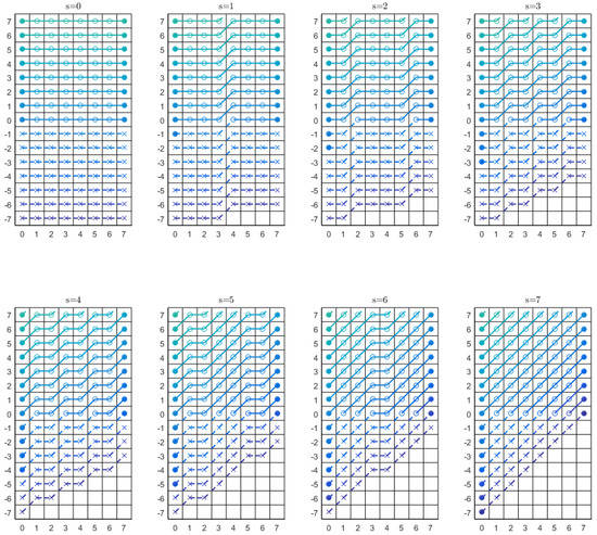
Figure 5.
A depiction of the whole set of discrete lines covering the displacements and slopes, as computed by conventional DRT.
Notice that each line joins a point with coordinates , with the point at . The inner points of those lines have the integer coordinates , that is . The crosses depict the values previously filled with zeroes. The circles are the input data. When there is a cross on the left, column 0, it means that the discrete line with that slope and displacement will never touch the image; a circle on the left, even if with negative displacement, means that it will sum different than zero (for a non-null image).
The algorithm exhibits linearithmic complexity because any two-points line segment, for example the one that joins the points and , will be computed only once and then reused when needed. In this case, when computing results with parameters , , , and . This holds true for every segment, computed on any scale.
The zeroes padded to the input at the first stage make the input double in size and, therefore, doubles the number of operations at each stage, just to accomplish the completeness in slopes and intercepts, even if a lot of partial sums on this region will never be used: for example the sums of pixel at with or the pixel at with .
2.2. Full Sinogram Construction
Equations (3)–(5) constitute the core of the DRT algorithm for the basic quadrant with angles between 0 and 45 degrees. A discrete version of the full sinogram can be accomplished, reusing the algorithm that solves a quadrant by applying it another thrice to versions of the input where axis are swapped and/or flipped conveniently and their partial outputs merged in a four times bigger global result. A typical output was shown in the rightmost image of Figure 1.
Figure 6 depicts the behavior of the basic quadrant algorithm in the subfigure (a). The other subfigures explain how the rest of the angles could be computed.
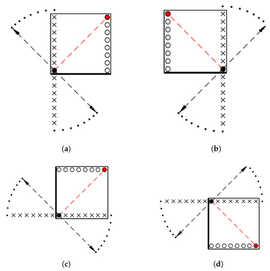
Figure 6.
Schemes of behavior of the 4 quadrants of a full DRT. Each quadrant covers angles of projection. Together they cover all projection angles. (a) Quadrant covering angles; (b) ; (c) ; (d) .
The schemes on the subfigures follow these conventions:
- The black filled circle will be considered our {0, 0} reference point.
- The reference point will be joined by discrete lines, with the empty circles on the opposite extreme; so, those empty circles depict the plurality of the slopes to be considered.
- The reference and the slopes are at the extremes of an axis marked with a coarse black line. This axis is coincident with the discrete line with null displacement and slope.
- For the maximal slope, the reference point will be joined with the red circle. This line of maximal slope is one of the diagonals of the plane and has, as normal, the vectors depicted with dashed arrows. Those can be interpreted as positives or negatives.
- The rest of discrete lines, those corresponding to the ascents from 1 to , have, as a finishing vertex of their normals, the black dots that describe arches close to the axis, where crosses are depicted.
- Those crosses represent the displacements that must be considered.
2.3. Radon Adjoint Transform
To achieve an inverse Radon transform, it is necessary to define, previously, the adjoint transform.
As can be seen in the next terms: the forward transform computes from an input image, the summation of pixel values through a set of lines, which is complete in slopes and displacements.
The adjoint transform is such that, for every point in the Radon domain, corresponding to a certain slope and displacement, it redistributes uniformly that summation value back to the image domain, assigning the same quantity to every pixel traversed by the line. That, obviously, is not the inverse transform, but (and that is the key of the contribution from William H. Press [16]) it is a sufficiently good starting point for inducing an iterative refinement process.
The adjoint discrete Radon transform is defined by the inverse mapping of Equation (5):
Figure 7 shows the adjoint operator working independently on the four quadrants of a forward DRT, as well as the sum of all of them.

Figure 7.
The adjoint discrete Radon transform, as defined by Equation (6), applied on each quadrant of the forward transform of the image, used as example through this paper. The image on the right corresponds to the adjoint of the whole DRT and is equivalent to the sum of the four images in the left. It is reminiscent of the unfiltered back-projection method used in medical imaging.
2.4. Radon Inverse Transform
Now, the inverse, or backward, Radon transform algorithm can be built upon this adjoint transform. The adjoint transform will be used as an approximate inverse operator of the forward transform in the theory of iterative improvement of a solution to linear equations, described in chapter 2.5 of the numerical recipes book from, again, Press [26].
This method, by itself, is extremely slow to converge. In order to accelerate this inversion, so that it becomes fast, exact, and practical, Press suggests to use a multi-grid approach, described in the same book [26], chapter 19.6. In Figure 8, the images depicts the convergence after just five iterations. Press demonstrated that, in spite of being iterative, it can be properly called a fast inverse, because convergence, up to the resolution of the machine, never takes more than a few iterations. Additionally, it is well conditioned, so that noise does not preclude the inversion.

Figure 8.
The first 5 iterations of recursive multi-grid inverse Radon transform of a DRT.
3. Central DRT
3.1. Discrete Lines in Central DRT
Figure 9 shows, similarly to Figure 5 for conventional DRT, how the discrete lines of central DRT operate on a image. Input data must still be padded in the displacement dimension, but an increase of rows is sufficient. This scheme shows an increase of rows, for the sake of comparison with Figure 5.
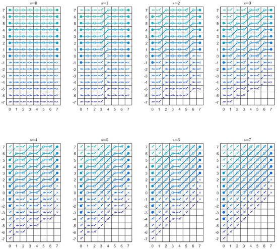
Figure 9.
A depiction of the whole set of discrete lines covering the displacements and slopes, as computed by central DRT.
The circles in the first column of each rectangle are the displacements that the central DRT will compute for that slope. Now, they will always be N independently of the slope. Their position, in order to maintain centered with the line that crosses the image through its centre, descends as s increase. Lines whose displacements verify or will simply be ignored.
3.2. Memory Footprint at Partial Transforms
The proposal of central DRT arises from the finding that if we prune the computations of the values outside this central band, as a collateral effect, half of the values at partial transforms do not need to be evaluated. Remember that the discarded output values represent less than 15% of Radon summations on input data; this is because the zones to be discarded basically operate on the zones padded with zeroes. So, for certain applications, they can safely be ignored.
Pruning techniques have a very reduced effect in fast Fourier transform [27]: from to , when only coefficients are required. This is, to achieve the same reduction by half of computations, on a 256 1D FFT, the output size should be limited to just 16 coefficients. This reduction by half of computations, when halving required coefficients in an already linearithmic transform, was unexpected.
Figure 10 shows the memory patterns of data required for the computation of a quadrant of central DRT for an image of size , that is, . The rectangles represent, visually, if a value at partial stages , as defined by Equation (4), is needed to compute the central DRT; in that case, it is shown in gray and, otherwise, in black.
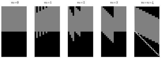
Figure 10.
Memory patterns of data required for computing central DRT on a image.
This depiction reveals that, at each partial stage, only N adjacent values must be computed per column.
The other finding is that the pattern, observed here, for (that sort of sawtooth on the first horizontal half of each stage) follows a formula that will be described later.
3.3. Central DRT Algorithm
Unraveling this access pattern is, in itself, the algorithm that is being looked for, since it will be enough to operate exactly as in conventional DRT but only on the highlighted zones. The algorithm described, however, will add another improvement: the DRT can be formulated with pointwise sums of N-length vectors lying on different columns, thus paving the road to an efficient implementation on SIMD arithmetic units.
So, instead of offering a formula for each value d, it is possible to operate on N consecutive values of two columns on a previous stage to achieve another N-length vector that comprise the required data at a column on a later stage. The indications of where each N-length vector of interest starts (for a given stage, size, and slope) is provided next.
It can be demonstrated that the computation relationship between columns, shown in Figure 10, is in accordance with the diagram shown in Figure 11.
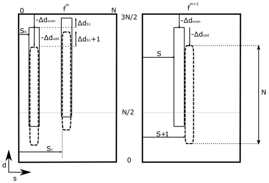
Figure 11.
Data related in the computation of two consecutive columns, with indexes S and , at stage , from two columns of the previous stage, with indexes and .
Let us consider the data at a certain stage () that will be calculated from data from the previous stage (m). The index m, denoting the stage, will range from 0 to , with . Let S be an index at an even column, followed at an odd position by index , both belonging to stage . In order to calculate the required N values of each of these columns, it is necessary to add together two vectors of length N, coming from columns with indexes and . The starting point, over the d axis, of the vectors to add will be expressed according to the schema and depend on values , and .
The index S will be subdivided according to its binary expression, as follows:
Then, the indexes of stage m will be expressed as:
To calculate the starting point of the vector on the other axis, d, we have to define:
With this value, we can calculate: , , and
In these formulas, and are, respectively, the rounding operators to the next larger and smaller integer; the symbol refers to the binary shift and < is the lower than comparison, evaluated to 0 or 1.
Those values are applied following the schema on Figure 11:
- N data in column S, descending from row index , are the result of adding N data in column , descending from row index , and N data in column , descending from row index .
- N data in column , descending from row index , are the result of adding N data in column , descending from row index , and N data in column , descending from row index .
The resulting algorithm can be found in pseudo-code as Algorithm A1. The last for loop rectifies the central band, so that the output is a square.
Figure 12 shows the vectors to be added at each stage of the algorithm for a image. From left to right and from bottom to top: initial stage, partial stages, and final stage of the transform. Each stage, labeled as , with , shows data positions that will be acceded to calculate the next stage. Accesses for even column computations are shown with flat corners, whilst odd columns accesses are shown with rounded corners.
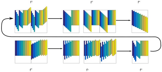
Figure 12.
N-length vectors lying on different columns to be added at each stage of the algorithm for a image.
At each stage of the computation, there will be two memory buffers storing the data at stages m and . Here, for the sake of depiction, accesses from odd and even columns are shown isolated; otherwise, they would overlap. However, they access the same columns for a pair of S and computation, only with different starting row indexes. The result of the computation at a stage is shown again as input for the next step of the transformation.
It can be seen in the schema how, in each stage, only the data required by a later stage are computed. During the transformation, positions outside the zone are sometimes acceded. These accesses are simply ignored because they would add zeros.
An example of output of central DRT will be shown later, after exposing the periodic DRT algorithm.
4. Periodic DRT
Equations (3)–(5) remained untouched when defining central DRT, because it computes the same as conventional DRT, only for fewer values. The algorithm had to be modified to operate on half of the values, but the operations carried out on those values did not change. Now, it will be the opposite; the algorithm remains mostly untouched from conventional DRT, but there will be a slight change in Equation (4).
It is desirable, in the case of periodic DRT, that discrete lines do not abandon the square region where the input is defined. Instead, if for a certain slope and displacement a discrete line is going to cross the upper limit through position , it will be forced to reenter at position .
This line wraparound effect is normally undesired because such definition of lines turns the transform useless for tomographic inversion. In Fourier-based transforms, this effect is counteracted by additional padding. However, some applications can benefit from a collateral effect of this redefinition of discrete lines: the forward transform that emerges has a fast inversion algorithm, something that central DRT does not.
In Figure 13, the expected behavior for discrete lines in periodic DRT is depicted. Lines with parameters will finish now on positions . To accomplish such behavior, the partial transform equation must be redefined:
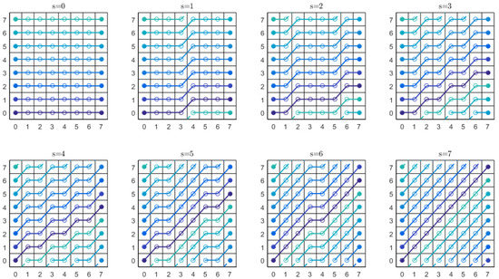
Figure 13.
A depiction of the whole set of discrete lines covering the displacements and slopes, as computed by periodic DRT.
That change translates directly into the mapping equation:
The input image must not be padded now. The algorithm for a quadrant is given in Algorithm A2. This algorithm is a more direct translation of the equations defining the transform than before, on central DRT, because operations are performed again at datum level, not on N-length vectors.
The output can be rectified by applying a circular shift of magnitude to each column of the four quadrant outputs, .
5. Results and Discussion
5.1. Time Measurements and Quality of Reconstructions
Later in this section, we will cover the similarities and differences between our two proposed methods, but let’s start by comparing them with previously available methods for computing Radon transform, in terms of our main motivation: speed. In that sense, we will measure how they compare with three methods that represent the plethora of available Radon transform algorithms. The three selected methods for comparison will be: the conventional multi-scale discrete Radon Transform, which is the direct ancestor of our propositions; a method representing those based on Fourier projection-slice theorem, namely the pseudo-polar Fourier-based Radon transform, PPFRT; and one covering the main alternative, whose lines can dispense with interpolation: the Mojette transform, in particular, the fast Mojette transform, FMT.
The methods we will compare with, in each case, will be run on the same platform, with the most optimised versions provided by the different authors; the times will be averaged for 100 runs. The type of data in the multi-scale transforms will be integers, with floating points in the rest, reflecting the nature of each method.
The conventional DRT has been programmed in C++ by us but is an almost direct transposition from the appendices of Press’ article [16]. As a reference for the Fourier-based methods, we have used the one provided by Shkolnisky [28]. In spite of coming packaged for Matlab environment, most of its time is devoted to FFT computations, which are optimal, even if Matlab itself is suboptimal for time measurements. As a representative of the Mojette family, we have selected the fast Mojette transform, which can be found on the Finite transform library [29]. Pseudo-polar Radon transform is based on the Fourier slice-projection theorem; then, the core 2D Fourier algorithm, within the method, is computed on a non-Cartesian grid: the pseudo-polar Fourier transform, running on concentric squares, where points are equispaced in slopes. This is essential to guarantee results free of artifacts. The number of coefficients (displacements × angles) computed by this algorithm is , where N is the number of elements on a dimension of the input image. The now proposed methods return the same number of coefficients, but the conventional DRT computes . The Mojette transform, to be commented subsequently, can operate with much less: .
Mojette transform uses a set of infinitesimal Dirac lines, whose slopes are rational: they can be written as the inverse tangent of an irreducible rational fraction. The number of angles computed in the test were N + N/2, as recommended by the authors, and without redundancy, . There is not a fast forward Mojette transform available in the software package.
Tests were conducted on an Intel i5-6600 CPU with 16 GB of RAM running Arch Linux. This is a 64-bit CPU with 4 cores running between 3.3 and 3.9 GHz. It is not capable of hyper-threading.
There are some interesting things to note in Figure 14. First, the multi-scale methods, denoted in the graph as DRT, CDRT, and PDRT, are sequential implementations that almost directly translate the provided pseudo-code, and they were not optimised. The central and periodic DRT are, at least, twice as fast as conventional DRT. Even these non-optimised versions are much faster than the widespread Fourier-based methods. FMT remains faster.
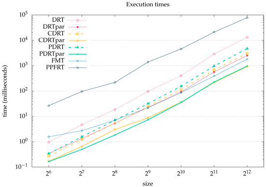
Figure 14.
Log–log representation of execution times (in milliseconds) for different algorithms and sizes of input on the same CPU platform. DRT stands for conventional DRT, whilst CDRT and PDRT are our proposed central and periodic DRT. FMT stands for fast Mojette transform. PPFRT stands for pseudo-polar Fourier-based Radon transform; par stands for parallel versions.
It must be taken into account that, in order not to penalize the FMT, the times reported are those of its backward transform. While the rest were evaluated for forward transforms. FMT is dozens of times faster in the backward transform than in the forward transform, due to the low number of back-projections it considers. However, it is unable to keep the same pace in both applications that we will show later: line detection and Curvelet transform, as its forward transform, is impractical for real-time implementations.
In summary, for non-parallel implementations on CPU, the periodic and conventional DRT have a similar performance to FMT and were much faster than PPFRT. Again, if a forward and backward pair is needed, the PPFRT will be preferable to the FMT, which only excels in the backward path.
When we port multi-scale methods to the Halide [30] parallel language, –denoted by DRTpar, CDRTpar and PDRTpar–, then our proposed methods achieve a result even better than FMT. Notice that FMT cannot be further optimised, as it uses the FFTW [31] library underneath, and it has already minimized the angular sampling density ( vs. ). Regarding the behaviour between our proposed methods and the conventional DRT, in these parallel versions, both periodic and central DRT reduce even more than the 1:2 factor suggested by the number of operations. We think this could be a combined effect of the minor memory footprint and a better coherence of memory accesses.
Encouraged by these results, we will propose, in a later section, to take the central DRT to a mobile phone, in order to test whether we can support video acquisition rates, 30 fps. That implementation will be written in OpenCL language and run on the GPU of the mobile phone. In Figure 15, we show how the multi-scale DRT transforms behave when executed on a PC’s GPU, again, programmed with Halide.
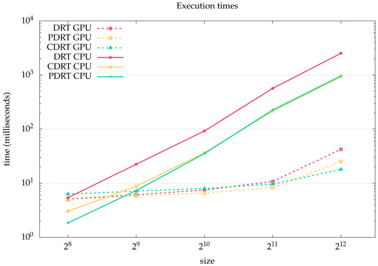
Figure 15.
Log–log representation of execution times (in milliseconds) for multi-scale DRT algorithms on CPU and a NVIDIA Geforce GTX 1080 GPU. DRT stands for conventional DRT, whilst CDRT and PDRT are our proposed central and periodic DRT.
The CPU versions reported are those parallelised, and they were already faster than Fourier-based Radon transforms on CPU. Now, porting them to GPU starts to bring benefits for sizes larger than 1024, as, less than that, the dominant times come from data movement and synchronizing between CPU and GPU. Basically, on a powerful GPU, we could sustain, with the proposed methods, 30 fps acquisition rates, even on 4K video streams.
As a final note, regarding the backward transforms, the periodic DRT results are completely analogous to those of conventional DRT, in terms of quality. Central DRT has no inverse. For a more detailed assessment on how conventional DRT, and, hence, periodic DRT, compares with the Fourier-based transform and the Mojette transform, see Kingston et al. [24].
5.2. Comparison of Central and Periodic DRT
Figure 16 shows the output of conventional, central, and periodic DRTs, when fed with the image containing two black circles on a white background, shown on a corner of the conventional DRT output. Those two circles have diameters of 240 px and 120 px, in a square image. Additionally, four pixels in the center of the image are black.
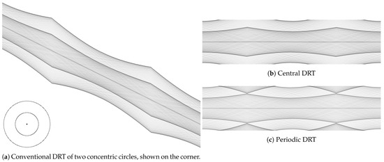
Figure 16.
Conventional DRT (a), Central DRT (b), and Periodic DRT (c) of a image of two concentric circles, shown bottom left of first subfigure.
Those images reveal the internal functioning of each DRT. The particular shape of conventional DRT can be noticed, in order to contemplate every possible displacement and slope. Central DRT contains the central band of conventional DRT rectified, with the center of the image projecting always in the central displacement of the DRT, at index . The periodic DRT can be considered as a mixture of both, in the sense that the displacement dimension now remains of size N, independent of the slope; however, those projections, not considered in central DRT, are now again present, but that added to a position already occupied by another displacement of the central band.
The value occupying position in conventional DRT separated values, with respect to the displacement of the center of the image, , for a certain slope s, i.e., , will be added to the value in periodic DRT.
5.3. Adjoint Operators of Central and Periodic DRT
Both proposed transforms have an adjoint, also called back-projection, operator. In the case of periodic DRT, it will be based on the inverse mapping of Equation (8):
In the case of central DRT, the Equation (6) remains valid. Apart from that, the adjoint operator has to repeat every step on the forward transform but in the reverse order, with the outer loop of algorithm for a quadrant descending from to .
Figure 17 shows the result of applying the respective adjoint operators on a previously forward transformed image, containing equispaced deltas, for each type of transform: conventional, central, and periodic (in that order from left to right).
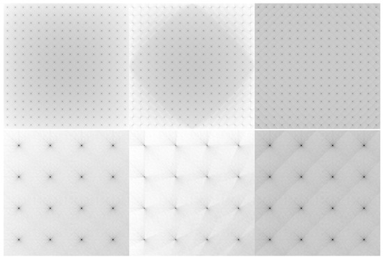
Figure 17.
Top row, from left to right, the respective adjoint operators applied to the conventional, central, and periodic forward DRTs of an input, constituted by equispaced black pixels. Bottom row, details of top left corners of back-projections in the same order.
There is a sort of vignetting in conventional DRT, due to the different length of discrete lines that are considered in this method: every line traverses N values, but depending on the slope and displacement, more or less of those values correspond to real pixels on the input image or zeroes in the padded zone.
The back-projected result, corresponding to central DRT, is equivalent to that of conventional DRT but inside of the rhomboid with vertexes , and . The vignetting effect is very notorious outside that zone. Moreover, the shapes around each (originally) black dot are not symmetric: those shapes are lacking the discrete lines discarded by this method.
The back-projection corresponding to periodic DRT is the more symmetric of the three results, and it is not affected by the vignetting effect; simply all N values considered for each value of the output have effectively traversed the N pixels of the input.
5.4. Convergence of Inversion Algorithm
With the aforementioned adjoint operators, the same technique described by Press [16] for conventional DRT has been applied to central and periodic DRT.
Convergence of inversion of periodic DRT is as fast as that of conventional DRT.
In the case of central DRT, even if the eigenvalues of the multiplication of the adjoint and forward operators, expressed as matrices, are lower than one, the convergence of its backward transform is fast, only in the previously mentioned rhomboid central zone. Outside of that zone, it converges so slowly that it ruins the speedup gained on the forward step.
The inversion method, proposed by Press, reduces the error on image domain, based on observations of the error on Radon domain, where the trace of cornered line integrals are basically absent.
Figure 18 shows the behavior of combined forward and back-projection transforms for each DRT type, operating on an input with a horizontal line inside the rhombus, inscribed in a square zone, described for central DRT and additional smaller lines, slanted and positioned closer to each corner.
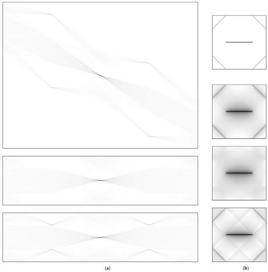
Figure 18.
Forward and back-projected transforms of an input, consisting of one horizontal line in the center and four lines closer to the corners. From top to bottom: conventional, central, and periodic DRT. (a) Forward transforms; (b) Input and back-projections.
The cornered lines are part of those not considered by central DRT, and they leave no trace, neither in the forward transform nor in the back-projection. On the other hand, the back-projection, in the case of periodic DRT, is good enough for the method to converge.
Figure 19 shows the quality of inversion achieved for each type of DRT after three and five iterations. Surprisingly, periodic DRT performs even better than conventional. Central DRT inversion is only valid in the central rhomboid zone.
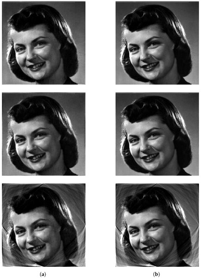
Figure 19.
From top to bottom, quality of the inversion for conventional, periodic, and central DRTs. (a) Inversion after three iterations; (b) Inversion after five iterations.
6. Example of Central DRT Application
A suitable problem for demonstrating the capacity of central DRT transform is the automatic localization of rectangles on images taken with cameras of smart devices. In this context, the use of central DRT provides an important speedup (at the cost of omitting some cornered lines).
Implementation on Mobile Devices
Central DRT has been devised with its vectorized implementation in mind: it not only computes less sums than conventional DRT, its formulation have also been modified to operate on vectors, instead of single values. Additionally, central DRT has been adapted for this application, by operating on unsigned, 16-bit integers. It is easy to avoid arithmetic overflow when it is the relative value that is important (and not the absolute values).
Table 1 shows the computation times for central DRT run on an Android™ smart-phone, and the transform is computed on the GPU. A demonstrative execution of the application has been provided as Supplementary Materials, a screenshot can be seen in Figure 20. The position on Radon space of the most prominent edges are highlighted. With this information, the rectangle is determined in image coordinates; simultaneously, the output of DRT is being shown, in order to verify the ability to compute the DRT on an smart-phone camera preview pipeline.

Table 1.
Measured times, in milliseconds, of an Android™ application, running a GPU implementation of the central DRT on different SoCs with different resolutions.
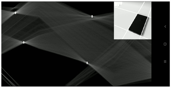
Figure 20.
Screen recording of a smart-phone executing the demonstrative application. The camera input is shown on the top-left corner. The rest of the image is the output of the central DRT of the gradient magnitude. Four maxima are highlighted and back-projected to image domain.
The camera is initialized and put in preview mode at around 30 frames per second and at a resolution of (depending on light conditions). These frames are converted to a single luminance (grayscale) channel of 16-bit depth. Then, it is cropped to or and fed to the kernel that calculates the gradient magnitude, which outputs another image of the same resolution. The gradient magnitude output image is then processed by the central DRT, giving a four times wider output as a result. This output is resized to fill the whole screen and converted to the screen display format (32 floating point ARGB); an overlay, containing the input image, is added.
The processing time of the central DRT on the Snapdragon™ 835 [32] is 16% faster than the 821 [33], and the 845 [34] is 40% faster. Halving the resolution on both dimensions yields an average speedup of 70%. With all this in mind, for terminals equipped with a Snapdragon™ 845, it is possible to acquire full resolution images and process them, after resizing to , at 30 frames per second. The vectorized central DRT, along with the rest of the pipeline, was programmed on OpenCL™. Given that the whole process happens in the GPU, the computation times do not vary a lot and, given the nature of the Android environment, it does not suffer visibly from throttling, as it drastically would when running the same processes on CPU. The measured times showed variations of only 2–5%.
The use of this transform, in the context of automatic localization of bar-codes, has been patented by the company Wooptix [35]. The use of Radon transform to accurately localize a bar-code on smart-phones has been prohibitive until now [36,37]. We believe that the use of central DRT can drastically enhance the applicability of Radon (or its equivalent, Hough transform) in several fields, due to the achieved reduction of execution times.
7. Example of Periodic DRT Application
Periodic DRT has a similar complexity to central DRT and adds the benefit of having a fast inversion algorithm. It would not have been of use in the previous demonstration because of the periodicity it recreates at image domain. However, another field that suits its properties has been found.
An invertible, discrete Curvelet transform, running exclusively in integer arithmetics, was introduced in [38]. Inside Curvelet transform, conventional DRT was used at the Radon level. In the conclusions of that work, it was remarked that the computation times should be reduced, so that the important benefits of using Curvelets as a focus estimator in the shape-from-focus technique could be really useful.
It is the case that conventional DRT can be safely replaced by periodic DRT, as the founding transform of the discrete, first generation Curvelet transform, without affecting the quality of inversion.
With the very slight modifications suggested in Equations (7) and (8), the measured times show a speed-up of for the forward transform and for the inverse transform when using periodic over the conventional DRT pair. The measurement has been done in an implementation written in Python3, with the aid of Cython [39] to include a C implementation for those parts that take the most of the computation time. The Wavelet transform has been implemented using the library PyWavelets, available in [40]. The results are indistinguishable to those obtained when using conventional DRT as founding block of Curvelet. An example of reconstruction, after hard thresholding in the Curvelet domain, is shown in Figure 21. Notice that the original image, taken from the Press article [16], has a lot of compression artifacts that are efficiently removed with Curvelet thresholding. A lesser divergence has been found in the degree of smoothness, which seems bigger for the same factor of thresholding when using a periodic, instead of conventional, DRT. However, by simply readjusting this correction factor, the results coincide again.

Figure 21.
From left to right: detailed of images, recovered with Curvelet inverse transform after thresholding at 100%, 85%, and 75% of the accumulated magnitude of coefficients, obtained from Curvelet forward transform, which employs periodic DRT as founding tool for computing ridgelets.
8. Conclusions
In this work, two new variations to discrete Radon transform, with a multi-scale approach, have been introduced. Both reduce the number of computations of conventional DRT, almost by half. Depending on the deployment platform, this translates into a halving of execution times, compared to the fastest alternative available, to the best of our knowledge. The methods benefit greatly when ported to parallel languages and GPUs.
The central DRT is of interest as a substitute to conventional DRT whenever a forward Radon transform is required, but not its inverse. The other useful condition is that, for the field of application, lines at the corners can mostly be ignored.
The usefulness of periodic DRT may seem reduced, but it is exactly what was required, in order to accelerate the computation of the discrete Curvelet transform.
In two recent papers, we have extended the conventional, multi-scale DRT to perform summation on planes and lines, in a three-dimensional volume [41]; we proposed an advantageous backward transform, based on filtered back-projection [42], again for the conventional DRT. We think both proposed central and periodic DRT will be equally extensible to three dimensions, and, in the case of periodic DRT, the filtered back-projection approach also seems feasible.
The search for deepening the knowledge of discrete Radon transforms will be continued in the future. Some of the objectives that remain open are:
- A fast inversion algorithm for central DRT.
- The manner to operate on non-square domains.
- An algorithm to simultaneously compute more than one quadrant at a time.
- The efficient implementation of the whole Curvelet pair of transforms on smart-phones.
Supplementary Materials
The following are available online at https://www.mdpi.com/article/10.3390/app112210606/s1: Video S1: A screen recording of a demonstration mobile phone application that uses the proposed central DRT to detect, in real-time, the most prominent rectangle seen by the device’s camera.
Author Contributions
Conceptualization, J.G.M.-H. and Ó.G.-C.; methodology, J.G.M.-H. and J.M.R.-R.; software, Ó.G.-C., J.P.L., and J.G.M.-H.; validation, Ó.G.-C.; formal analysis, J.G.M.-H. and J.M.R.-R.; visualization, J.G.M.-H.; writing—original draft preparation, J.G.M.-H.; writing—review and editing, J.P.L., Ó.G.-C., and J.M.R.-R.; project administration, J.M.R.-R. All authors have read and agreed to the published version of the manuscript.
Funding
This research was partially funded by ‘Estrategia de Especialización inteligente de Canarias RIS-3’, Government of the Canary Islands, and European Regional Development Fund, under grant number ProID2020010066, as well as “Promotion of open dissemination of research excellence results”, University of La Laguna, and the Council of Economy, Knowledge and Employment of the Government of the Canary Islands. J.G.M.-H. was partially supported by Wooptix S.L., through ‘Convenio de colaboración Wooptix-Universidad de la Laguna, 2019–2020’.
Institutional Review Board Statement
Not applicable.
Informed Consent Statement
Not applicable.
Data Availability Statement
Data sharing is not applicable to this article. The images in the experiments are the result of applying the provided algorithms, and are available on request from the corresponding author.
Conflicts of Interest
The authors declare no conflict of interest. The funders had no role in the design of the study; in the collection, analyses, or interpretation of data; in the writing of the manuscript, or in the decision to publish the results.
Abbreviations
The following abbreviations are used in this manuscript:
| ARGB | Alpha Red Green Blue |
| CPU | Central Processing Unit |
| DRT | Discrete Radon Transform |
| FFT | Fast Fourier Transform |
| FFTW | Fast Fourier Tranform in the West [31] |
| FMT | Fast Mojette Transform |
| fps | Frames per Second |
| GPU | Graphical Processing Unit |
| SFF | Shape From Focus |
| SIMD | Single Instruction Multiple Data |
| SoC | System on Chip |
| PPFRT | Pseudo-Polar Fourier Radon Transform |
Appendix A
| Algorithm A1 Compute the central DRT of a quadrant |
| Input: Image f(x, y), consisting of data. Output: Central Radon transform of f, (s, d), consisting of data.
|
| Algorithm A2 Compute the periodic DRT of a quadrant |
| Input: Image f(x, y), consisting of data. Output: Periodic Radon transform of f, (s, d), consisting of data.
|
References
- Radon, J. Über die Bestimmung von Funktionen durch ihre Integralwerte längs gewisser Mannigfaltigkeiten. Akad. Wiss. 1917, 69, 262–277. [Google Scholar]
- The Nobel Prize in Physiology or Medicine. Nobel Prize Outreach AB 2021. 1979. Available online: https://www.nobelprize.org/prizes/medicine/1979/summary/ (accessed on 7 November 2021).
- Kak, A.C.; Slaney, M. Principles of Computerized Tomographic Imaging; Society of Industrial and Applied Mathematics: Philadelphia, PA, USA, 2001. [Google Scholar]
- Berenguer, Y.; Payá, L.; Valiente, D.; Peidró, A.; Reinoso, O. Relative Altitude Estimation Using Omnidirectional Imaging and Holistic Descriptors. Remote Sens. 2019, 11, 323. [Google Scholar] [CrossRef]
- Qin, H.; He, X.; Yao, X.; Li, H. Finger-vein verification based on the curvature in Radon space. Expert Syst. Appl. 2017, 82, 151–161. [Google Scholar] [CrossRef]
- Rim, D. Dimensional Splitting of Hyperbolic Partial Differential Equations Using the Radon Transform. SIAM J. Sci. Comput. 2018, 40, A4184–A4207. [Google Scholar] [CrossRef]
- Takezawa, Y.; Hasegawa, M.; Tabbone, S. Camera-captured document image perspective distortion correction using vanishing point detection based on Radon transform. In Proceedings of the 2016 23rd International Conference on Pattern Recognition (ICPR), Cancun, Mexico, 4–8 December 2016; pp. 3968–3974. [Google Scholar] [CrossRef]
- Hansen, P.C.; Saxild-Hansen, M. AIR Tools—A MATLAB package of algebraic iterative reconstruction methods. J. Comput. Appl. Math. 2012, 236, 2167–2178. [Google Scholar] [CrossRef]
- Bracewell, R. The Projection-Slice Theorem. In Fourier Analysis and Imaging; Springer: Boston, MA, USA, 2003; pp. 493–504. [Google Scholar] [CrossRef]
- Averbuch, A.; Coifman, R.R.; Donoho, D.L.; Israeli, M.; Shkolnisky, Y. A Framework for Discrete Integral Transformations I-The Pseudopolar Fourier Transform. SIAM J. Sci. Comput. 2008, 30, 764–784. [Google Scholar] [CrossRef]
- Hough, P.V. Method and Means for Recognizing Complex Patterns. US Patent 3,069,654, 18 December 1962. [Google Scholar]
- Duda, R.O.; Hart, P.E. Use of the Hough Transformation to Detect Lines and Curves in Pictures. Commun. ACM 1972, 15, 11–15. [Google Scholar] [CrossRef]
- Matus, F.; Flusser, J. Image representations via a finite Radon transform. IEEE Trans. Pattern Anal. Mach. Intell. 1993, 15, 996–1006. [Google Scholar] [CrossRef]
- Guedon, J.; Normand, N. Mojette transform: Applications for image analysis and coding. In Proceedings of the Visual Communications and Image Processing, San Jose, CA, USA, 8–14 February 1997. [Google Scholar] [CrossRef]
- Dulio, P.; Pagani, S.M. A rounding theorem for unique binary tomographic reconstruction. Discret. Appl. Math. 2019, 268, 54–69. [Google Scholar] [CrossRef]
- Press, W.H. Discrete Radon transform has an exact, fast inverse and generalizes to operations other than sums along lines. Proc. Natl. Acad. Sci. USA 2006, 103, 19249–19254. [Google Scholar] [CrossRef]
- Götz, W.; Druckmüller, H. A fast digital Radon transform—An efficient means for evaluating the Hough transform. Pattern Recognit. 1996, 29, 711–718. [Google Scholar] [CrossRef]
- Brady, M.L. A fast discrete approximation algorithm for the Radon transform. SIAM J. Comput. 1998, 27, 107–119. [Google Scholar] [CrossRef]
- Brandt, A.; Dym, J. Fast calculation of multiple line integrals. SIAM J. Sci. Comput. 1999, 20, 1417–1429. [Google Scholar] [CrossRef][Green Version]
- Hsung, T.C.; Lun, D.; Siu, W.C. The discrete periodic Radon transform. IEEE Trans. Signal Process. 1996, 44, 2651–2657. [Google Scholar] [CrossRef]
- Averbuch, A.; Coifman, R.R.; Donoho, D.L.; Israeli, M.; Shkolnisky, Y.; Sedelnikov, I. A Framework for Discrete Integral Transformations II-The 2D Discrete Radon Transform. SIAM J. Sci. Comput. 2008, 30, 785–803. [Google Scholar] [CrossRef]
- Averbuch, A.; Coifman, R.; Donoho, D.; Israeli, M.; Waldén, J. Fast slant stack: A notion of Radon transform for data in a Cartesian grid which is rapidly computable, algebraically exact, geometrically faithful and invertible. SIAM Sci. Comput. 2001, 37, 192–206. [Google Scholar]
- Averbuch, A.; Shkolnisky, Y. 3D Fourier based discrete Radon transform. Appl. Comput. Harmon. Anal. 2003, 15, 33–69. [Google Scholar] [CrossRef]
- Kingston, A.; Svalbe, I.; Guédon, J.P. The discrete Radon transform: A more efficient approach to image reconstruction? In Developments in X-ray Tomography VI; Stock, S.R., Ed.; International Society for Optics and Photonics, SPIE: Brussels, Belgium, 2008; Volune 7078, pp. 144–153. [Google Scholar] [CrossRef]
- Marichal-Hernandez, J.G.; Luke, J.P.; Rosa, F.L.; Rodriguez-Ramos, J.M. Fast approximate 4-D/3-D discrete Radon transform for lightfield refocusing. J. Electron. Imaging 2012, 21, 023026-1. [Google Scholar] [CrossRef]
- Press, W.H.; Teukolsky, S.A.; Vetterling, W.T.; Flannery, B.P. Numerical Recipes in C; Cambridge Univ Press: Cambridge, UK, 1982; Volume 2. [Google Scholar]
- Sorensen, H.V.; Burrus, C. Efficient Computation of the DFT with Only a Subset of Input or Output Points. IEEE Trans. Signal Process. 1993, 41, 1184–1200. [Google Scholar] [CrossRef]
- Shkolnisky, Y. Pseudo Polar Fourier Transfom. Last updated on September 2014. Available online: https://sites.google.com/site/yoelshkolnisky/software (accessed on 7 November 2021).
- Chandra, S.S. Finite Transform Library. Last updated on December 2018. Available online: https://github.com/shakes76/finite-transform-library (accessed on 7 November 2021).
- Ragan-Kelley, J.; Adams, A.; Sharlet, D.; Barnes, C.; Paris, S.; Levoy, M.; Amarasinghe, S.; Durand, F. Halide: Decoupling Algorithms from Schedules for High-performance Image Processing. Commun. ACM 2017, 61, 106–115. Available online: http://halide-lang.org/ (accessed on 7 November 2021). [CrossRef]
- Frigo, M. A Fast Fourier Transform Compiler. In Proceedings of the ACM SIGPLAN 1999 Conference on Programming Language Design and Implementation, PLDI ’99, New York, NY, USA, 1–4 May 1999; Association for Computing Machinery: New York, NY, USA, 1999; pp. 169–180. [Google Scholar] [CrossRef]
- Snapdragon 835 Mobile Platform. Available online: https://www.qualcomm.com/products/snapdragon-835-mobile-platform (accessed on 7 November 2021).
- Snapdragon 821 Mobile Platform. Available online: https://www.qualcomm.com/products/snapdragon-821-mobile-platform (accessed on 7 November 2021).
- Snapdragon 845 Mobile Platform. Available online: https://www.qualcomm.com/products/snapdragon-845-mobile-platform (accessed on 7 November 2021).
- Gómez-Cárdenes, Ó.; Rodríguez-Ramos, J.M. Barcode Detection Method. WO Patent 2019219512A1, 21 November 2019. Available online: https://patentscope.wipo.int/search/en/detail.jsf?docId=WO2019219512 (accessed on 7 November 2021).
- Muniz, R.; Junco, L.; Otero, A. A robust software barcode reader using the Hough transform. In Proceedings of the 1999 International Conference on Information Intelligence and Systems (Cat. No.PR00446), Bethesda, MD, USA, 31 October–3 November 1999; pp. 313–319. [Google Scholar] [CrossRef]
- Zamberletti, A.; Gallo, I.; Albertini, S.; Noce, L. Neural 1D Barcode Detection Using the Hough Transform. IPSJ Trans. Comput. Vis. Appl. 2015, 7, 1–9. [Google Scholar] [CrossRef][Green Version]
- Gómez-Cárdenes, Ó.; Marichal-Hernández, J.G.; Trujillo-Sevilla, J.M.; Carmona-Ballester, D.; Rodríguez-Ramos, J.M. Focus measurement in 3D focal stack using direct and inverse discrete radon transform. In Three-Dimensional Imaging, Visualization, and Display 2017; International Society for Optics and Photonics: Brussels, Belgium, 2017; Volume 10219, p. 102190R. [Google Scholar]
- Cython: C-Extensions for Python. 2021. Available online: http://cython.org/ (accessed on 7 November 2021).
- PyWavelets. 2021. Available online: https://github.com/PyWavelets (accessed on 7 November 2021).
- Marichal-Hernández, J.G.; Gómez-Cárdenes, Ó.; González, F.L.R.; Kim, D.H.; Rodríguez-Ramos, J.M. Three-dimensional multiscale discrete Radon and John transforms. Opt. Eng. 2020, 59, 1–23. [Google Scholar] [CrossRef]
- Marichal-Hernández, J.G.; Oliva-García, R.; Gómez-Cárdenes, Ó.; Rodríguez-Méndez, I.; Rodríguez-Ramos, J.M. Inverse Multiscale Discrete Radon Transform by Filtered Backprojection. Appl. Sci. 2021, 11, 22. [Google Scholar] [CrossRef]
Publisher’s Note: MDPI stays neutral with regard to jurisdictional claims in published maps and institutional affiliations. |
© 2021 by the authors. Licensee MDPI, Basel, Switzerland. This article is an open access article distributed under the terms and conditions of the Creative Commons Attribution (CC BY) license (https://creativecommons.org/licenses/by/4.0/).