Article

Design and Test of Load-Lifting Performance for Hydraulic Linkage of the High-Medium Horsepower Tractor

1
State Key Laboratory of Automotive Simulation and Control, Jilin University, Changchun 130022, China
2
Key Laboratory of Bionic Engineering, Ministry of Education, Jilin University, Changchun 130022, China
3
College of Biological and Agricultural Engineering, Jilin University, Changchun 130022, China
4
Luoyang Tractor Research Institute Co., Ltd., Luoyang 471039, China
5
Mechanical and Electrical College, Hainan University, Haikou 570228, China
*
Author to whom correspondence should be addressed.
Appl. Sci. 2021, 11(20), 9758; https://doi.org/10.3390/app11209758
Submission received: 25 August 2021 / Revised: 5 October 2021 / Accepted: 11 October 2021 / Published: 19 October 2021
(This article belongs to the Section Robotics and Automation)

Abstract

:

Featured Application

The present study could provide a reference for the loading and lifting apparatus design to test the hydraulic lifting device for the large-medium horsepower tractor.

Abstract

To improve the detection efficiency and safety of the tractor, the research proposed a device for detecting the loading–lifting performance of the lower link of the tractor based on the four-bar mechanism. According to the actual use requirements and the testing standards, the critical components in the device were designed. The dynamic analysis of the load-lifting device was carried out by dynamic simulation, and the component strength in the machine was checked by the finite element simulation method. The results showed that the designed device could realize the hooking and connection of the lower link without an artificial method. The average cost of the device was 5.13 s to realize the connection with the lower link, and it took 7.30 s to raise the lower hitch point to a set height, about 750 mm. The loading test showed that the device could keep the loading force of the lower link stable during the lifting process. The designed device could shorten the detection time of the tractor hydraulic linkage and improve the cost, safety, and efficiency of detection. The research could provide a reference for the design of hydraulic linkage detection devices for the large-medium horsepower tractors and help realize the intelligent detection of tractors.

1. Introduction

China is a large agricultural country. According to the reference [1] statistics, China’s agricultural planting area reached 1.167 × 10⁸ hectares in 2020. Tractors are one of the critical equipment types in the process of crop planting, harvesting, spraying, etc. The number of tractors held and sold gradually increases with the increase of the planting area. With the increasing agricultural area circulation in China, more and more small farms have been established. The demand for large and medium horsepower tractors is increasing. For example, China’s production of large and medium horsepower tractors was 3.46 × 10⁵ units, an increase of 23% compared to the previous year [1]. Additionally, the Chinese government formulated a special law to promote agricultural mechanization.
In China, the hydraulic linkage is widely used in large and medium-sized tractors, connected with rotary tiller, riding machine, seeder, and other agricultural machinery through the lower link [2,3,4,5]. The performance of hydraulic linkage directly affects the working quality and efficiency of the tractor in the field, such as depth of the rotary blade, sowing depth, etc. [4,6,7]. With the promotion of precision agriculture, the loading–lifting performance of the hydraulic linkage also affects the operation accuracy of agricultural machinery. Hence, it is required to test the load-bearing and lifting performance of the hydraulic linkage during the production process of the tractor [8,9,10]. Many methods have been developed to test the loading and lifting performance of tractor hydraulic linkages, such as the weight loading method, orifice loading method, and hydraulic loading method [11,12,13]. As the lower link in the hydraulic linkage system can swing horizontally in the horizontal direction, the existing test method requires an artificial connection between the test mechanism and the hydraulic linkage. This will reduce the test efficiency, precision, and safety factor, and easily cause casualties and other shortcomings [11,14]. Additionally, these methods cannot achieve continuous loading of the hydraulic linkage. The research team investigated some tractor manufacturers (for example, Yto Group Corporation, which has a complete tractor product series in China), and found that it takes 10 to 15 min to test the hydraulic linkage. Meanwhile, these methods also need to dig trenches on the test site, which further decreases the safety of the tractor test. In recent years, with the introduction of “Made in China 2025” and some key science and technology plans in China, intelligent agricultural machinery equipment is one of the key development areas in these plans [15]. Therefore, there is an urgent need for a new method in the engineering field to actively connect the tractor lower link to improve the test efficiency and safety of the tractor hydraulic linkage.
In order to realize the intelligent test of the hydraulic linkage of the tractor before leaving the factory, the study proposed an automatic test device for the load-bearing and lifting performance of the hydraulic linkage. The designed tractor hydraulic linkage hook test device was analyzed from the kinematics and mechanics. Based on the analysis results, the automatic test device for load-bearing and lifting performance of the hydraulic linkage was optimized and developed. Additionally, a test of the hooking, loading, and lifting performance was carried out. The research can provide a reference for the tractor to develop a hydraulic linkage hooking test device, realize the unmanned hooking during the test process. Additionally, the safety and efficiency of the tractor hydraulic linkage test are improved, and the detection cost is reduced. The present study can provide a reference for the design of lifting devices of other types of tractors.

2. Device Design

The hydraulic linkage (model SZ804-55E-010, purchased from Yto Group Corporation) widely used in large and medium horsepower tractors is adopted during the present study. The lifting force range of the hydraulic linkage device used in the test is 17~36 kN. Based on the actual use requirements and the [16,17], the test indexes for the adopted hydraulic linkage are shown in Table 1.

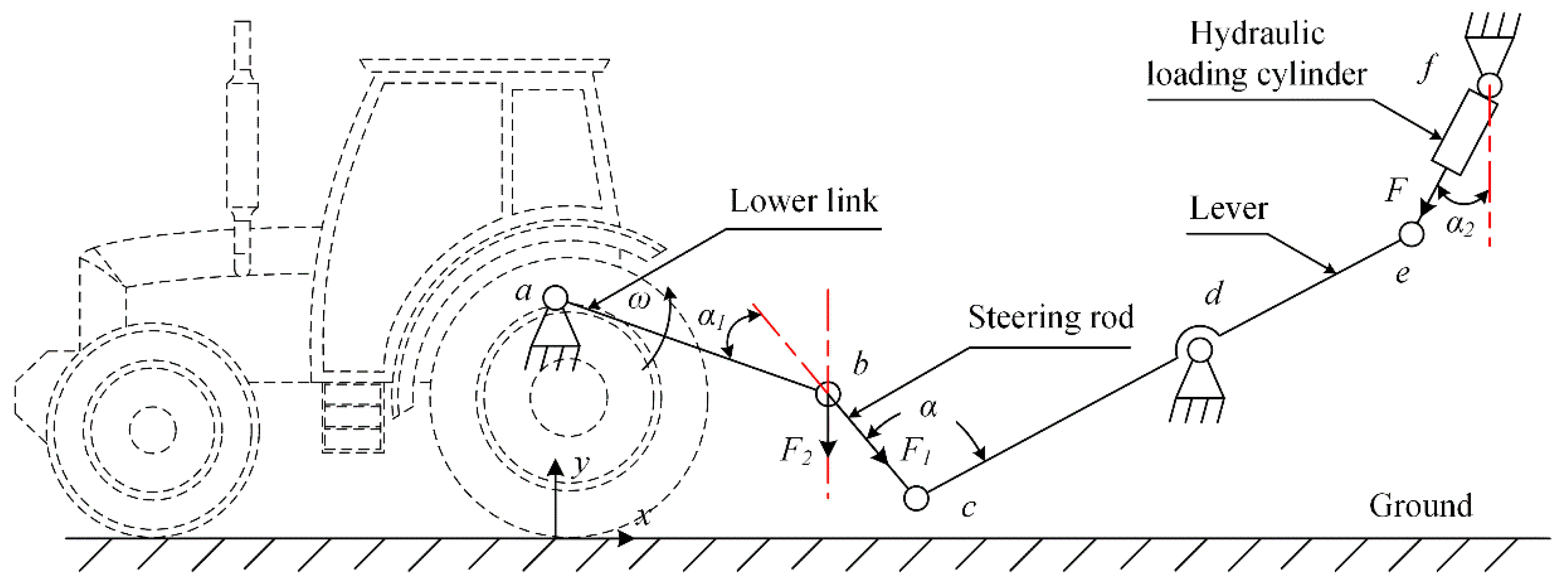
2.1. Principle of Design

Combined with the investigation and published literature [2,11,12,13,14], the test process of the load-lifting capacity of the tractor hydraulic linkage can be divided into the connection stage of hydraulic linkage and test device, and the load-lifting stage. The hooking stage includes two processes: the limit of the lower link and the connection between the load-lifting device and the lower link. Meanwhile, the movement track of the lower link point is arc-shaped during the lifting process (as shown in Figure 1), so the hydraulic linkage lifting device is designed based on a four-bar mechanism. Meanwhile, the hydraulic linkage lifting device designed in the present study would not dig trenches on the test site to increase test safety.
The load-lifting device for testing hydraulic linkage was designed based on the four-bar mechanism and took hydraulic to load the lower link, as shown in Figure 1. The linkage (ab rod in Figure 1) was the lower link connected to the tractor and rotated with point a as the center of the circle during the lifting process. Due to the large lifting stroke of the lower link of the large and medium-sized tractors and the high position of point a, a ce lever was added into the four-bar mechanism to change the lifting direction during the operation process and improve the safety factor. The bc rod played the role of steering and connecting the ab rod and the ce rod during the lifting process. During the rotation of the lower link, the steering rod bc was driven, and a hydraulic loading cylinder was used to load the e end of the lever.
The load-lifting device was designed according to Figure 1, as shown in Figure 2. According to the lifting process of the tractor hydraulic linkage, the device was composed of the lower link catching system, a connection system between the lifting device and the lower link, and a load-lifting system. The ce lever was loaded by the hydraulic pump station connected with the hydraulic loading cylinder, and then the load was applied to the lower link. Meanwhile, the displacement sensor was added to the device to record the height of the lifting position of the lower link during the lifting process.

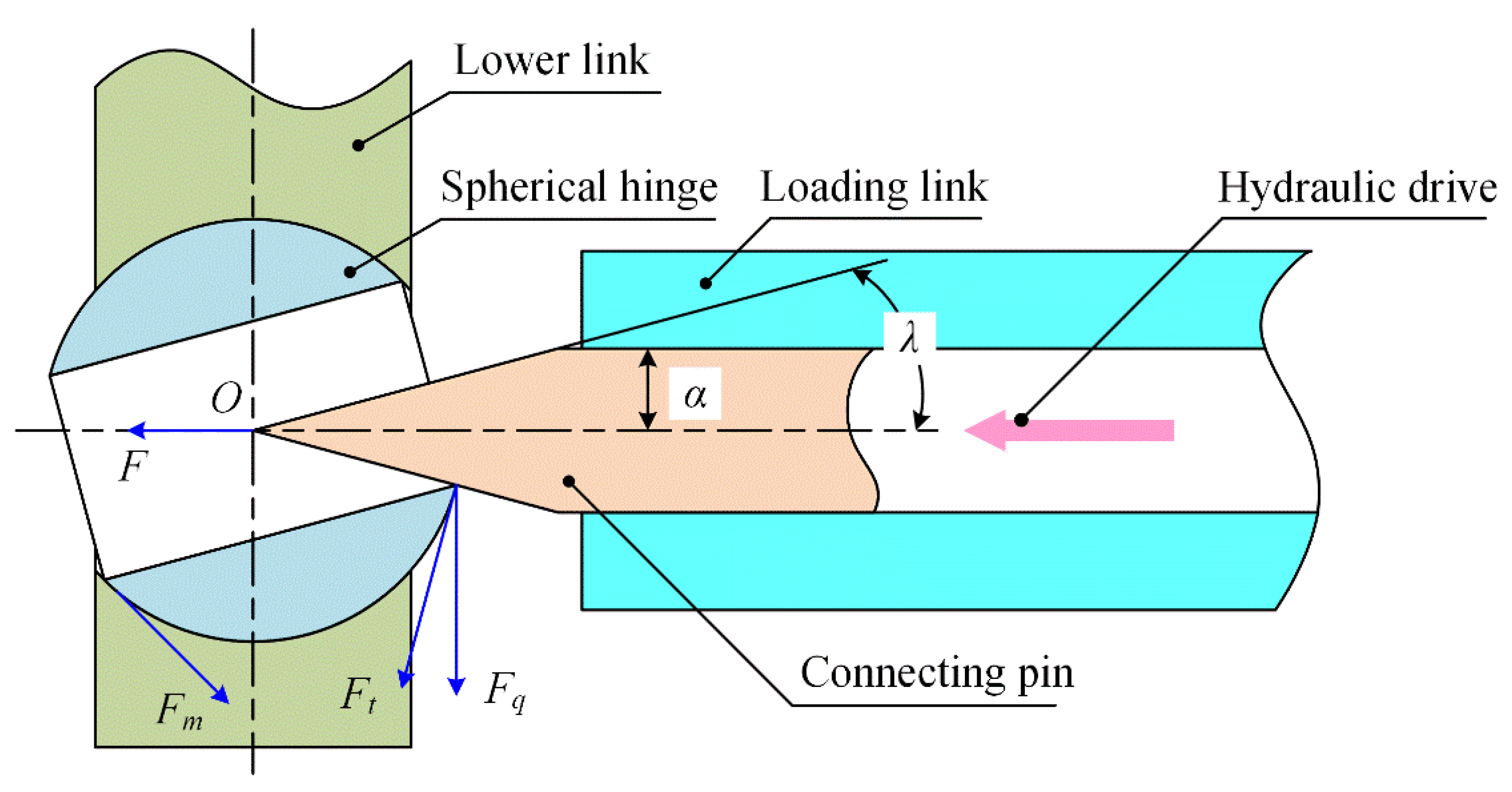
2.2. Hooking Structure

Since the lower link could swing laterally on the axle, the lower link could first be caught and limited during the lifting process. The “∩” structure was adopted in the device to capture the lower link, as shown in Figure 3. To restrict the lower link, L2 should meet the following requirements:
{ L 2 2 L 1 + L 0 L 1 L 0 + Δ
where L0 was the width of the lower link, and L1 and L2 were the widths of the upper and lower grooves of the limiting component, respectively. Δ was the fit clearance between the lower link and the upper groove, and the range was 3~5 mm. When the lower link moved to the upper groove on the “∩” part, the movement of the lower link was limited to facilitate the connection between the lower link and the load-lifting device.

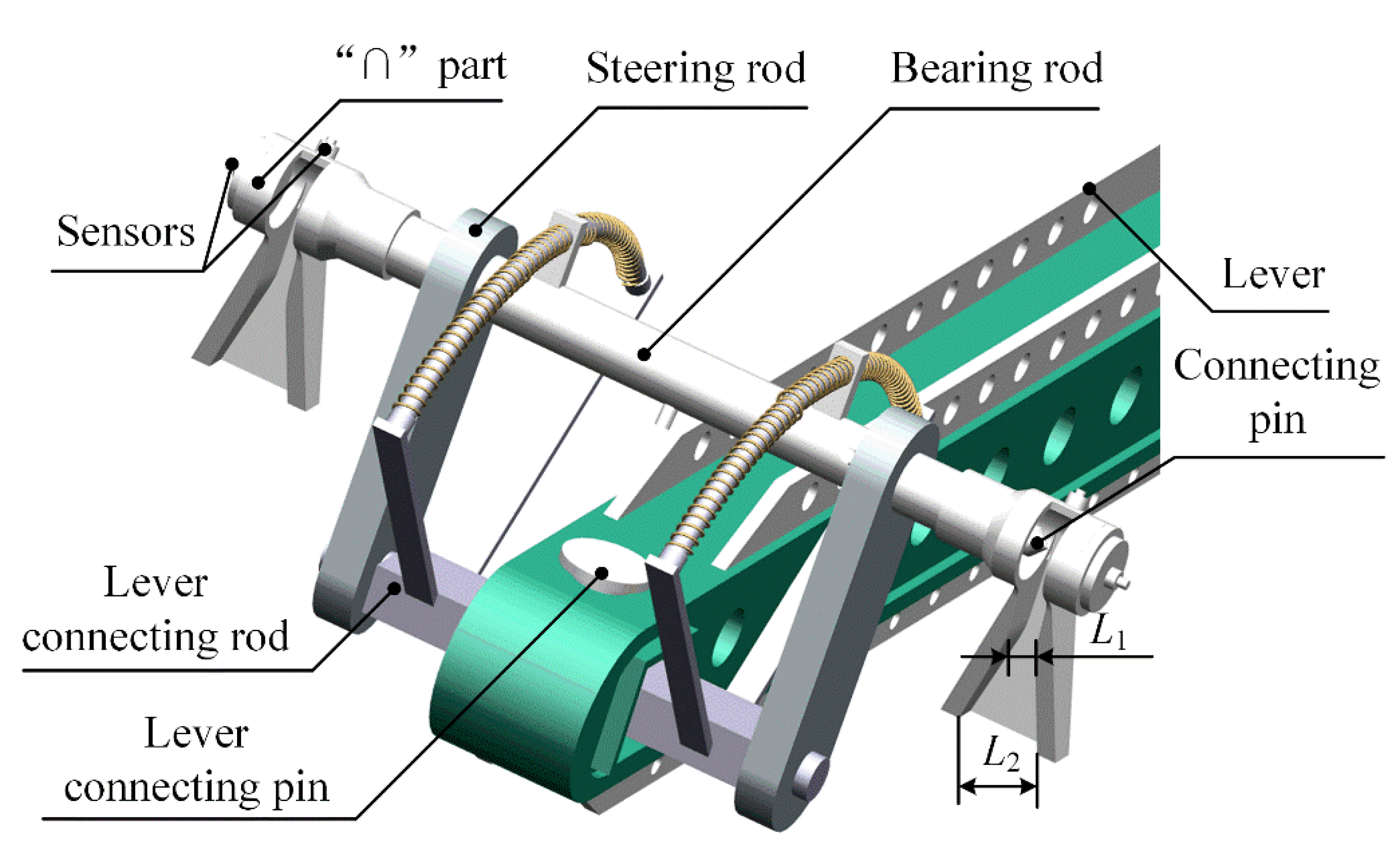
2.3. Connecting Structure

The test process of the load-lifting capacity of the tractor hydraulic linkage could be divided into the connection stage of hydraulic linkage and test device, and the load-lifting stage. To avoid the influence of the manual connection between the lower link and loading device on staff safety, Figure 4 showed the mechanism to realize the unmanned connection between the tractor and the loading device. Two connecting pins and a hydraulic cylinder were built in the loading link, and the connecting pin was driven to realize the connection between the device and the lower link under the action of the hydraulic cylinder. Whether the connection is successful can be confirmed by the color change of the sensor indicator.
The spherical hinge of the lower link used to connect agricultural equipment is prone to tilt, and the axis of the spherical hinge is not parallel to the axis of the hole. Therefore, the manual way is often used to level during the previous test. The shape of the connecting pin in the device would affect whether the lower link could be connected to the device under this condition.
During the movement of the connecting pin through the spherical hinge, it is necessary to overcome the frictional force of the rotation of the spherical hinge. Additionally, the load torque is required to be less than the driving torque of the spherical hinge. Hence, to ensure that the spherical hinge can rotate during the connection process, the shape of the connecting pin should meet the following conditions:
{ { F m = f v F q F q = F tan λ F t = F sin λ { F t r > F m r F sin λ > F tan λ f v cos λ > f v
where F is the thrust of the connecting pin during the move process; Ft is the positive pressure on the spherical hinge; Fm is the friction of the spherical hinge; fv is the equivalent friction coefficient with a value of 0.2; Fq is the vertical component of the positive pressure of the spherical hinge; and λ and r are the taper angle and the radius of the connecting pin, respectively.
Meanwhile, the connecting pin could also bear the test load. The radius of the connection pin should conform to Equation (3):
{ τ = F A = F π r min 2 [ τ ] σ = M y I z = M max W z [ σ ] W z = π r min 3 4
where [τ] and [σ] are the characteristic strength parameters of 45# steel, and the safety factor was 1.5. rmin is the minimum radius of the connection pin. Iz is the inertial moment of the cross-section of the connection pin to the neutral axis; Wz is the bending section coefficient of the connection pin; Mmax is the maximum bending moment borne by the connecting pin. The tensile strength of 45# steel with a hardness of 197 HB is 600 MPa [18].
Therefore, the taper angle λ ranged from 0° to 78°, and the minimum radius of the connection pin was 7.8 mm. To facilitate penetration of the connection pin into the spherical hinge and meet the safety of the connection pin, the taper angle and diameter of the connection pin were 39° and 16 mm, respectively.

2.4. Load-Lifting Structure

The tractor lifting and loading device was composed of a ce lever rod, hydraulic loading cylinder, and other parts, as shown in Figure 1. The lever rod was 2700 mm, and the ratio of cd rod and de rod was 1:1. The hydraulic loading cylinder was connected with the hydraulic station, and the changes of the loading oil pressured during the load-lifting process are recorded in real-time.
According to Equation (4), the rectangular section parameters of the lever in the loading mechanism were determined.
δ max = M z max W z = F l d e B H 3 b h 3 6 H [ δ ]
where h and H are the inner and outer heights of the rectangular section, respectively. b and B are the inner and outer widths of the rectangular section, respectively. [δ] is the permissible stress of the 45# steel.

3. Simulation and Experiment

According to design requirements and the actual working conditions of the tractor, the initial hook position of the lower link was set at an angle of 20° with the horizontal direction. The height of the support point of the lever and the hydraulic cylinder from the ground was 650 mm and 1750 mm, respectively. When the vertical load of 40 kN (accuracy of 1% full scale) was applied to the lower link point, the height range that the lower link should lift was 750 mm (accuracy of 10 mm). The simulation analysis method could be used to analyze the kinematics and strength check of the device to help the design and optimization of the designed device [5,19]. Hence, the simulation method analyzed the kinematics and mechanical properties of the structure shown in Figure 2.

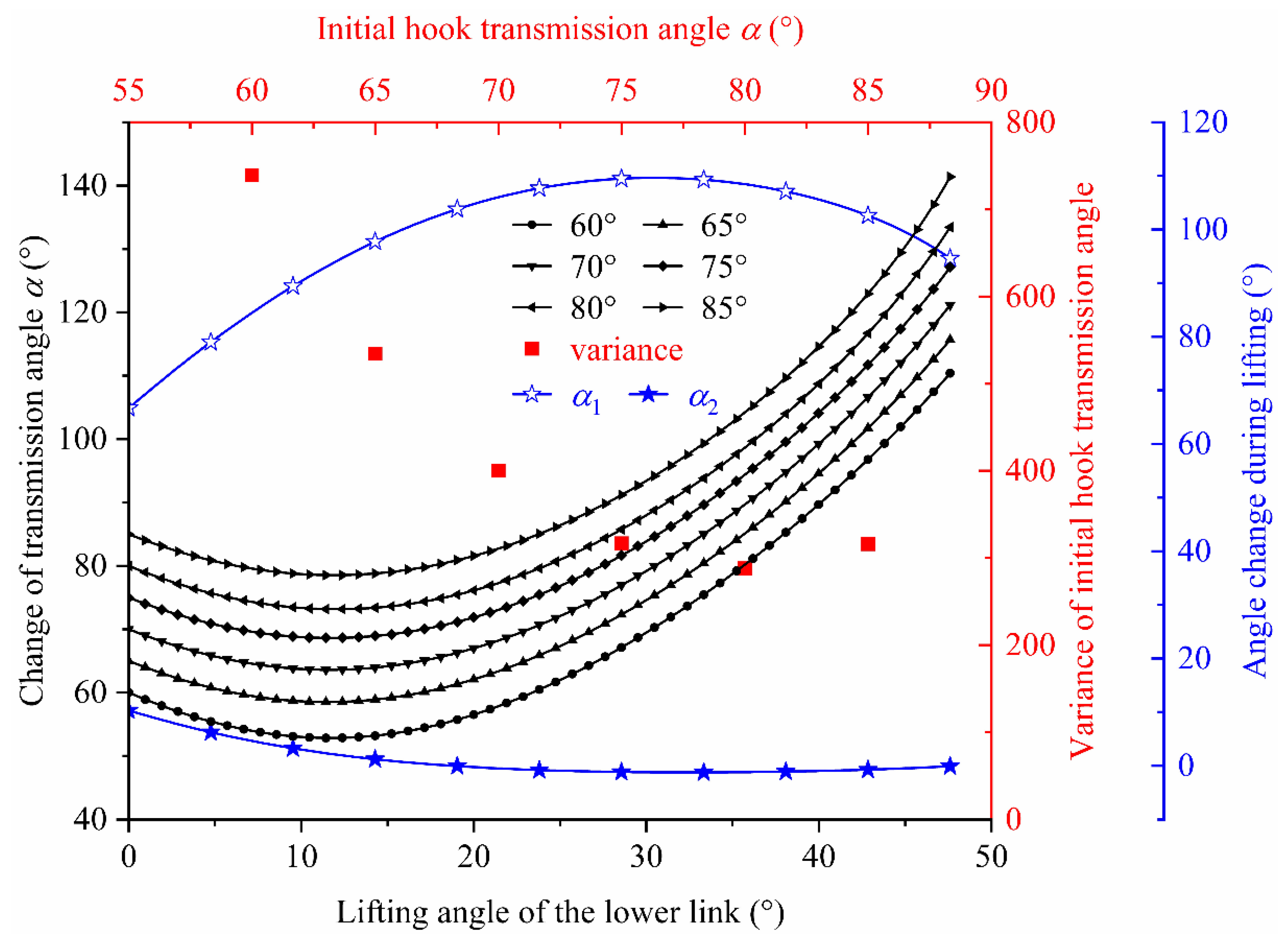
3.1. Kinematics Simulation

The transmission angle would affect the transmission efficiency, and the extrusion force on the lever shaft would increase. The model of the load-lifting device shown in Figure 2 was established and imported into Adams software. After simplifying the model, constraints and loads were applied to analyze the kinematics. When the angle between the initial position of the steering rod and the lever was at an ideal value of 90°, the lever rod rotated more than 44.3°, and the transmission angle α was too large. Therefore, the initial transmission angle needed to be optimized.
The initial hook transmission angle was, respectively, set at 60°, 65°, 70°, 75°, 80°, and 85°, and the analysis model was adjusted. The transmission angle during the lifting process was analyzed by using the software, and the variance of the transmission angle during the lifting process corresponding to different initial hook transmission angles was calculated, as shown in Figure 5. Based on the analysis results, it could be known that when the initial transmission angle between the bc rod and the cd rod was 80°, the variance was the smallest. It showed that the change of the transmission angle α in the lifting process was smaller than that in the lifting operation of other initial positions. When the initial hook transmission angle α was 80°, the range of α1 and α2 were 66.7°~109.65° and −1.25°~10.3°, respectively.
To maintain a constant load force of 40 kN on the lower link, a hydraulic loading cylinder was used for loading with variable force. The Adams software was used to calculate the load F applied by the hydraulic loading cylinder and the load F1 transmitted by the steering rod during the lifting process. The rotation angle of the lower link during the dynamic simulation analysis was one degree per second. The results were shown in Figure 6. F and F1 varied from 44,948~55,265 N and 40,001~43,554 N, respectively. These parameters could be used as the design basis for component strength calibration. Meanwhile, the load-lifting process could be carried out according to the parameters to ensure that the load force of the lower link was kept at 40 kN.
According to the dynamic simulation analysis results, the function equation of the loading force of the hydraulic cylinder during the loading and lifting process was fitted to check the strength of the design device. The fitting equation was shown in Equation (5), the fitting coefficient was high. Hence, the fitting equation could be used as one of the boundary conditions of the finite element simulation analysis.
F = 0.0388 t 4 3.3115 t 3 + 94.692 t 2 994.47 t + 45612 ,   R 2 = 0.9919
where F is the loading force of the hydraulic cylinder, N; t is the time for the lower to rise to the set height, s. The range of t varies from 0 s to 47.6 s.

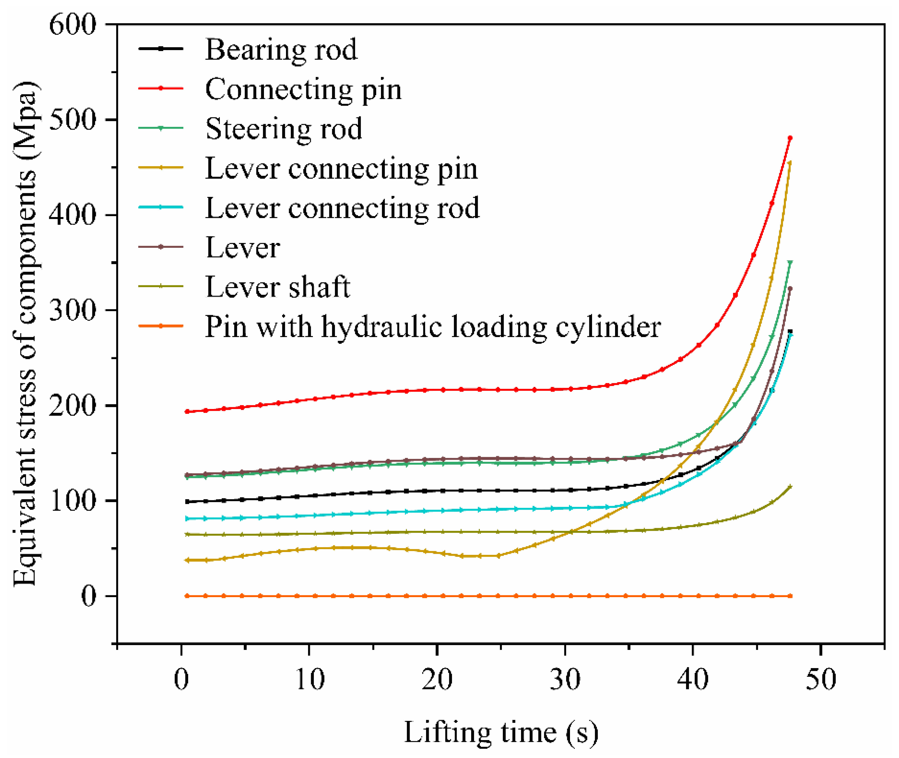
3.2. Mechanical Simulation

The model shown in Figure 2 was simplified in Workbench to analyze the transient stress–strain characteristics of the components during the load-lifting process. The transient-structural module in Workbench was used for analysis, and the boundary conditions were as follows: (1) the rotation speed of the lower link was 1°/s, and the rotation time was 47.6 s; (2) the driving force of the hydraulic cylinder was applied to the device according to the Equation (5); and (3) the analysis process was divided into 100 substeps. 45# steel was used as the component material. The transient analysis results of the critical components were shown in Figure 7.
It could be seen from the analysis results that the equivalent stress of the components changed significantly during the end stage of the lifting and loading process. In particular, the equivalent stresses of the connecting pin, bearing rod, steering rod, and lever connecting pin were close to the tensile strength of 45# steel. It was necessary to adopt the materials with better performance than 45# steel to make the key components of the device. To improve the use safety factor of the lifting and loading device, 40 Cr was used as the material of key components in the device, such as the connecting pin, lever connecting pin, and steering rod. The tensile strength of 40 Cr with a hardness of 207 HB is 980 MPa [18].

3.3. Loading and Lifting Test

The load-lifting device for testing the hydraulic linkage of large and medium horsepower power tractors was assembled, as shown in Figure 8. The hydraulic pump station in the designed device was purchased from Shenyang Boxroth hydraulic, and the control box was designed by Jilin Province Zhongyan Testing Equipment Co., Ltd (Changchun, China). The purchased hydraulic structure was placed at the same height as the tractor to leave the factory. The load-lifting device was connected with the control box and hydraulic station to monitor the change of height and loading force during the lifting process. Meanwhile, the movement of connecting pin and the loading of the hydraulic cylinder was control. In the test, the “∩” part moved downward driven by the hydraulic loading cylinder, and the lower link slid into the groove on the “∩” part. The connection pin realized the connection between the lower link and the load-lifting device under the action of hydraulic drive. The hydraulic loading cylinder loaded the lever to realize the loading of the lower link.

3.3.1. Hooking and Lifting Test
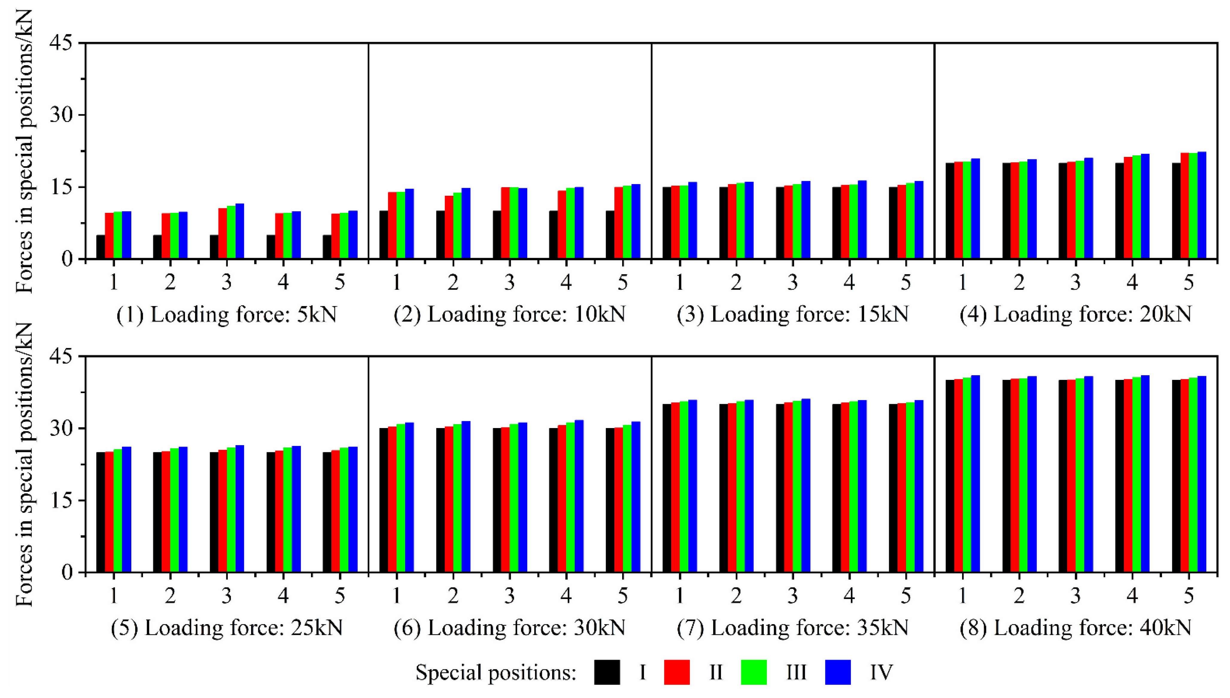
In the lifting test, the automatic hooking success rate β, the hooking time t1, the lifting time t2, and the lifting height h were used as the evaluation indicators of the load-lifting device. The test was repeated 20 times. The results were shown in Table 2. It could be concluded that the hydraulic linkage has good connecting and lifting performance, and the hooking success rate was 100%. The average hooking time of the device was 5.15 s, and the average lifting time was 7.30 s. The lifting height of the lower hitch point was greater than 750 mm, which met the testing requirements. Compared with the average 10~15 min of the manual hooking time, the load-lifting device could significantly shorten the hooking time, improve check efficiency and automation. Meanwhile, the device could realize the unmanned connection with the lower link of the tractor.

3.3.2. Loading Test

After the lower link was connected to the device at the initial position, the hydraulic loading cylinder was applied to the lower link to perform a load test. The actual load-bearing performance of the designed device was tested at the particular locations during the lifting process. The loading force of the lower link was increased by 5 kN. The initial value of the loading force of the lower link was 5 kN, and the maximum value was 40 kN. The loading test was repeated five times under the test conditions of different load forces.
During the lifting process, the particular positions were as follows: initial position of the lower link, the horizontal position of the lower link and the lever, the maximum height of the lower link. The four special positions were defined as Ι, II, III, and IV, respectively. When the components were in different special positions during the loading test, the loading force of the lower link was collected by the force sensor. The force sensor was purchased from Shenzhen Gensun Technology Co., Ltd. (China), with a capacity load of 100 kN and an error of ±0.05% of the full scale. The experimental results were shown in Figure 9.
According to the test results, when the initial loading force was 5 kN and 10 kN, the loading force of the lower rod could not be well maintained, and the loading force was increased with the continuous rotating of the lower link. This could be solved by increasing the hydraulic pipe diameter and increasing the return oil speed. When the loading force of the lower link exceeded 15 kN, the variation of the loading force on the lower link was small, and the load could be kept stable.

4. Discussion

The study designed a device based on the four-bar mechanism to test the lifting and loading performance of the hydraulic linkage of the large and medium horsepower tractor. According to kinetic analysis, strength check, and experimental results, it was shown that the designed device could meet the actual use requirements. Compared with the previous test methods, the designed device significantly shortened the detection time. Compared with the time consumed by the previous detection methods, the average hooking time between the device proposed by the present study and the lower link was 5.15 s. It could change the way of connecting with a tractor by manual method and improve the detection safety of the large and medium horsepower tractor. Additionally, the average lifting time of the device was 7.30 s to raise the lower link to a height of 750 mm to 760 mm. The test cost was reduced. Meanwhile, the device could avoid artificially connecting the loading device and the lower link during the test, which could improve the safety factor of the tractor test. The present study could provide a reference for the design of the loading–lifting performance test device of the large and medium horsepower tractor. Additionally, it could improve the intelligence and automation of tractor detection.

Author Contributions

Conceptualization, Q.C., Z.Y., J.X., B.M. and T.C.; methodology, Q.C., Z.Y., J.X., B.M., T.C., X.Z., L.W. and S.R.; validation, Q.C., Z.Y., J.X. and T.C.; literature search, Z.Y., J.X., B.M. and T.C.; figures, Z.Y., J.X. and T.C.; formal analysis, Q.C., Z.Y., J.X., B.M. and T.C.; investigation., Q.C., X.Z. and L.W.; resources, Q.C.; data curation, Z.Y., J.X., T.C., X.Z., L.W. and S.R.; writing—original draft, Z.Y., J.X. and T.C.; writing—review and editing, Q.C. and T.C.; visualization, Z.Y., J.X. and B.M.; supervision, Q.C. and T.C.; project administration, Q.C. and T.C. All authors have read and agreed to the published version of the manuscript.

Funding

This research has been supported by the National Key R&D Program during the 13th Five-year Plan Period, China, grant number 2017YFD0700202; and the State Key Laboratory of Automotive Simulation and Control, China, grant number 20171115.

Institutional Review Board Statement

Not applicable.

Informed Consent Statement

Not applicable.

Data Availability Statement

The data supporting the findings of this study are available in the article.

Conflicts of Interest

On behalf of all authors, the corresponding author states that there is no conflict of interest. The funder had no role in the design of the study; in the collection, analyses, or interpretation of data; in the writing of the manuscript; or in the decision to publish the results.

References

  1. National Bureau of Statistics of China. 2020 China Statistical Yearbook, 1st ed.; China Statistics Press: Beijing, China, 2020.
  2. Bentaher, H.; Hamza, E.; Kantchev, G.; Maalej, A.; Arnold, W. Three-point hitch-mechanism instrumentation for tillage power optimization. Biosyst. Eng. 2008, 100, 24–30. [Google Scholar] [CrossRef]
  3. Eltom AE, F.; Ding, W.M.; Ding, Q.S.; Tagar, A.A.; Talha, Z. Field investigation of a trash-board, tillage depth and low speed effect on the displacement and burial of straw. CATENA 2015, 133, 385–393. [Google Scholar] [CrossRef]
  4. Nielsen, S.K.; Munkholm, L.J.; Lamande, M.; Norremark, M.; Skou-Nielsen, N.; Edwards GT, C.; Green, O. Seed drill instrumentation for spatial coulter depth measurements. Comput. Electron. Agric. 2017, 141, 207–214. [Google Scholar] [CrossRef]
  5. Tarighi, J.; Ghasemzadeh, H.R.; Bahrami, M.; Abdollahpour, S.; Mahmoudi, A. Optimization of a lower hitch link for a heavy duty tractor using finite element method. J. Fail. Anal. Prev. 2016, 16, 123–128. [Google Scholar] [CrossRef]
  6. Nielse, S.K.; Munkholm, L.J.; Lamande, M.; Norremark, M.; Edwards GT, C.; Green, O. Seed drill depth control system for precision seeding. Comput. Electron. Agric. 2018, 144, 174–180. [Google Scholar]
  7. Wang, Y.X.; Jing, H.R.; Zhang, D.X.; Cui, T.; Zhong, X.J.; Yang, L. Development and performance evaluation of an electric-hydraulic control system for subsoiler with flexible tines. Comput. Electron. Agric. 2018, 151, 249–257. [Google Scholar] [CrossRef]
  8. Laceklis-Bertmanis, J.; Pirs, V.; Kronbergs, E.; Metla-Rozentals, A. Evaluation of hydraulic hitch-system improvement. In Proceedings of the 13th International Scientific Conference on Engineering for Rural Development, Jelgava, Latvia, 29–30 May 2014; pp. 74–78. [Google Scholar]
  9. Laceklis-Bertmanis, J.; Pirs, V.; Kronbergs, E.; Metla-Rozentals, A.; Metla, M. Hydropneumatic suspension for tractor implement. In Proceedings of the 11th International Scientific Conference on Engineering for Rural Development, Jelgava, Latvia, 24–25 May 2012; pp. 372–376. [Google Scholar]
  10. Mohammadikia, R.; Aliasghary, M. Design of an interval type-2 fractional order fuzzy controller for a tractor active suspension system. Comput. Electron. Agric. 2019, 167, 105049. [Google Scholar] [CrossRef]
  11. Chang, J.X. Research on hydraulic suspension technology of tractor. Adv. Intel. Syst. Res. 2017, 154, 552–555. [Google Scholar]
  12. Gao, Q.; Lu, Z.X.; Xue, J.L.; Gao, H.S. Design and test of hydraulic device for electro-hydraulic controlled hitch system of a horticultural tractor. Inmateh-Agric. Eng. 2020, 60, 253–260. [Google Scholar] [CrossRef]
  13. Meng, C.Y.; Li, G.Y.; Xu, F.; Li, J.F. Tractors hydraulics system stress testing design and experiment. IOP Conf. Ser. Earth Environ. Sci. 2019, 252, 032134. [Google Scholar] [CrossRef]
  14. Laceklis-Bertmanis, J.; Kronbergs, E. Model of hydropneumatic three point hitch. In Proceedings of the 12th International Scientific Conference Engineering for Rural Development, Jelgava, Latvia, 23–24 May 2013; pp. 49–54. [Google Scholar]
  15. National Manufacturing Strategy Advisory Committee. China Manufacturing 2025 Bluebook, 1st ed.; Publishing House of Electronics Industry: Beijing, China, 2018. [Google Scholar]
  16. GB/T 3871.4-2006. Agricultural Tractors-Test Procedures—Part 4: Rear Three-Point Linkage Lifting Capacity; General Administration of Quality Supervision, Inspection and Quarantine of China; Standardization Administration of China: Beijing, China, 2006.
  17. GB/T 1593-2015. Agricultural Wheeled Tractor-Rear-Mounted Three-Point Linkage-Categories 0, 1N, 1, 2N, 2, 3N, 3, 4N and 4; General Administration of Quality Supervision, Inspection and Quarantine of China; Standardization Administration of China: Beijing, China, 2015.
  18. Qin, D.T.; Xie, L.Y. Modern Handbook of Mechanical of Design, 1st ed.; Chemical Industry Press: Beijing, China, 2011. [Google Scholar]
  19. Seyedabadi, E. Finite element analysis of lift arm of a MF-285 tractor three-point hitch. J. Fail. Anal. Prev. 2015, 15, 737–743. [Google Scholar] [CrossRef]
Figure 1. Schematic diagram of load-lifting test of tractor hydraulic linkage. α1 is the angle between the ab rod and the bc rod; α is the transmission angle; α2 is the angle between the loading rod of the hydraulic cylinder and the vertical direction. F represents the loading force of the hydraulic cylinder; F1 is the actual loading force on the steering rod; F2 is the theoretical loading force, which should be a constant value of 40 kN according to the design requirements.
Applsci 11 09758 g001
Figure 2. Load-lifting device model for tractor hydraulic linkage.
Applsci 11 09758 g002
Figure 3. Catching mechanism of the lower link.
Applsci 11 09758 g003
Figure 4. Connection mechanism of the lower link and the lifting device.
Applsci 11 09758 g004
Figure 5. The changes of angle during the lifting process.
Applsci 11 09758 g005
Figure 6. Kinematics analysis of the load-lifting device.
Applsci 11 09758 g006
Figure 7. Equivalent stress of the device component during the lifting process.
Applsci 11 09758 g007
Figure 8. The load-lifting device of the lower link.
Applsci 11 09758 g008
Figure 9. Loading test.
Applsci 11 09758 g009
Table 1. Test indexes of hydraulic linkage for large and medium horsepower tractors.
Test RequirementsIndexes
Maximum lifting force40 kN
Number of lifts10
Lifting height750 ± 10 mm
Lifting time15 s
Table 2. Hitch and lifting test.
Noβ (%)t1 (s)H (mm)t2 (s)Noβ (%)t1 (s)H (mm)t2 (s)
1100576071110047606
2100676281210077607
3100476181310057606
4100676091410057597
5100675981510057587
6100475971610077568
7100476161710067616
8100576091810047617
9100576081910057617
10100676072010047608
Publisher’s Note: MDPI stays neutral with regard to jurisdictional claims in published maps and institutional affiliations.

