Article

A New Inspiration in Bionic Shock Absorption Midsole Design and Engineering

1
School of Physical Education, Quanzhou Normal University, Quanzhou 362000, China
2
Key Laboratory of Bionic Engineering (Ministry of Education, China), Jilin University, Changchun 130022, China
3
Beijing Institute of Mechanical Equipment, Beijing 100039, China
4
Faculty of Mathematics and Computer Science, Quanzhou Normal University, Quanzhou 362000, China
5
Key Laboratory of Intelligent Computing and Information Processing, Fujian Province University, Quanzhou 362000, China
6
Fujian Provincial Key Laboratory of Data Intensive Computing, Quanzhou 362000, China
*
Authors to whom correspondence should be addressed.
These authors contributed equally to this work.
Appl. Sci. 2021, 11(20), 9679; https://doi.org/10.3390/app11209679
Submission received: 3 September 2021 / Revised: 7 October 2021 / Accepted: 14 October 2021 / Published: 17 October 2021
(This article belongs to the Special Issue Artificial Intelligence in Medicine and Healthcare)

Abstract

:
Inspired by the performance of the ostrich in terms of loading and high-speed moving ability, the purpose of this study was to design a structure and material on the forefoot and heel of the middle soles of sports shoes based on the high cushioning quality of the ostrich toe pad by applying bionic engineering technology. The anatomical dissection method was used to analyze the ostrich foot characteristics. The structure and material of the bionic shock absorption midsole were designed according to the principles of bionic engineering and reverse engineering. F-Scan and numerical simulation were used to evaluate the bionic shock absorption midsole performance. The results showed that the bionic shock absorption midsole decreased the peak pressure (6.04–12.27%), peak force (8.62–16.03%), pressure–time integral (3.06–12.66%), and force–time integral (4.06–10.58%) during walking and brisk walking. In this study, the biomechanical effects to which the bionic shock absorption midsole structure was subjected during walking and brisk walking exercises were analyzed. The bionic midsole has excellent shock resistance. It is beneficial for the comfort of the foot during exercise and might reduce the risk of foot injuries during exercise.

1. Introduction

In the design and selection of sports shoes, the shock absorption properties have attracted increasing attention, and many shoe manufacturers now employ shock absorption as a selling point [1]. The shoe sole comprises three components, which are the insole, midsole, and outsole. The design of the soles depends very much on the mechanical characteristics of the material [2,3]. The material and structure of the midsole crucially affect the shock absorption properties of the shoes and are one of the most important bases of sports shoes [4,5]. During daily exercise, shoes are the first line of defense against the frequent impact of ground reaction force. Highly repetitious and large impact forces increase the risk of injury during exercise by generating extra vibrations in the body segments and subsequently causing head or joint damage [6].
Previous studies showed that the impact force during landing is buffered and dispersed by soft tissue, mitigating any painful sensation in the feet [7]. However, excessive impact force leads to stress fractures and knee joint injuries [8]. Therefore, the shock absorption function of sports shoes plays an essential role in protecting the body from sports injuries. Fine shock absorption properties can decrease the impact force on the feet and achieve a reasonable distribution of body weight across the plantar surface, with the benefits of preventing concussion of the brain [9], muscular system [10], and skeletal system [10,11]; minimizing sports fatigue [12]; improving comfort [10,11,12]; and enhancing sports performance [11,12].
Ostriches are the fastest biped in terrestrial locomotion [13]. They have an extraordinary speed and endurance, especially in deserts. Adult ostriches can continuously run at an average speed of 50–70 km/h for up to 30 min. Such a high-speed running ability is attributed to the muscles, tendons, legs, feet, and other anatomical structures, as well as their coordination [14]. Therefore, it is very desirable to take the ostrich foot as a bionic prototype and apply the excellent characteristics of the ostrich foot to the design of a shoe’s midsole.
The shock absorption ability of sports shoes is affected by the structure and materials, which are key factors in achieving a redistribution of plantar pressure through reasonable design [8]. Cushioning is a critical factor of a sports shoe. Wei et al. [15] reported the concept of cushion shock absorption to reduce the impact force during exercise and decrease the injury risk. A shock absorption sole is an ideal choice to decrease repeated impacts during exercise [15,16], especially in the midsole structure, which plays an important role in reducing the impact shock. Most shock absorption designs in footwear are focused on material selection or structure reform [16]. First, the research observed the ostrich toe pad anatomies, and then the toe pad parameters were applied in a shoe’s midsole design accordingly. Aside from that, the material selection and structure design of the forefoot and heel area are rarely investigated. Consequently, the shock absorption problems in this discipline remain unresolved. Nonetheless, the research and development of sports shoes with fine shock absorption properties is imperative [8,17]. Therefore, the purpose of this study was to design a structure and material on the forefoot and heel of the midsoles of sports shoes through bionic engineering.

2. Materials and Methods

There are three sections to this research: (1) the dissection method was used to analyze the anatomy of ostrich feet; (2) the structure and material of the bionic shock absorption midsole were designed according to the principles of bionic engineering and reverse engineering; and (3) physics tests and numerical simulations of the midsole performance were carried out.

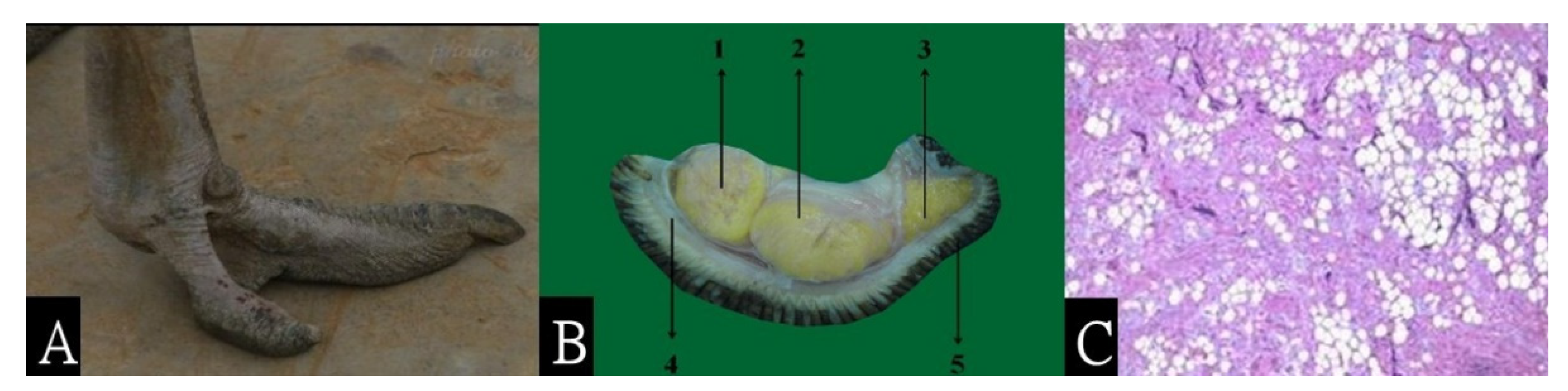
2.1. Ostrich Foot Dissection

Ostrich feet were collected from an ostrich farm in Jilin province in China. In total, 3 ostrich feet were dissected for this research. After butcher processing, the feet were immediately cryopreserved at a temperature of −20 degrees until the dissection date. The dissection tools included a scalpel, surgical scissors, and tweezers. The cushioning toe pad structures of the ostrich feet were measured as a basic parameter for bionic design. Each toe pad of the feet was surveyed 3 times.

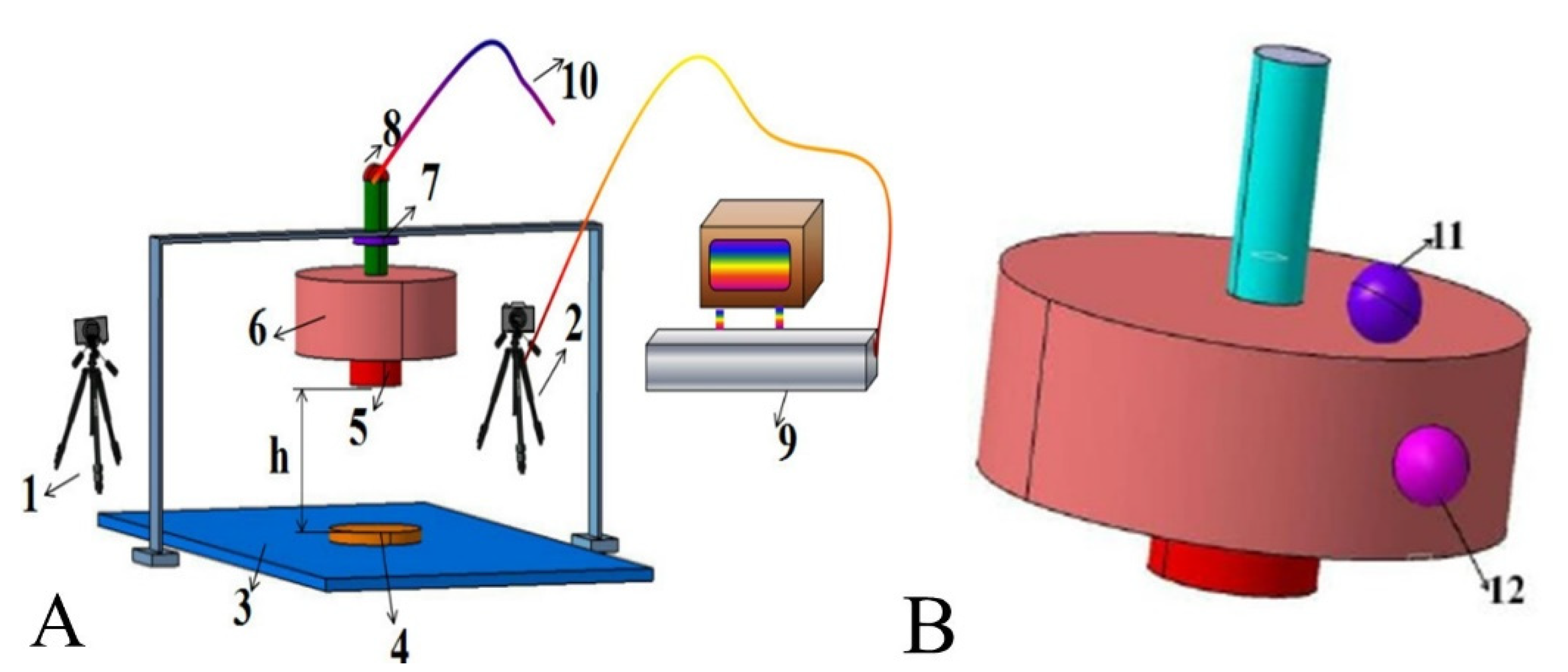
2.2. Physics Tests and Numerical Simulations

The hardness of the toe pad structure was tested with an LX-A Shore durometer according to the standard method (ISO 481984). Statics elastic tests of the ostrich toe pad structure were used in a universal testing machine (Yuxing, Inc., Shanghai, China) with an upper limit of 500 N and a 0.001-mm resolution. Corneal trephine (9 mm) was used to measure the density of the ostrich toe pad structure, and they were calculated according to the m/V formula.
A model of the midsole was constructed via the finite element method (FEM) and established based on contact and boundary loadings. The four equations of the midsole profile curves were as follows: Curve 1: y = 2 × 10 8 x 5 3 × 10 6 x 4 + 8 × 10 5 x 3 + 8 × 10 4 x 2 + 0.08 x 41.69 ( R 2 = 0.89 ) ; Curve 2: y = 4 × 10 8 x 5 3 × 10 5 x 4 + 9 × 10 3 x 3 + 1.41 x 2 102.11 x + 2861.9 ( R 2 = 0.91 ) ; Curve 3: y = 8 × 10 8 x 5 6 × 10 5 x 4 + 0.02 x 3 2.56 x 2 + 184.09 x 5336.9 ( R 2 = 0.91 ) ; and Curve 4: y = 2 × 10 8 x 5 3 × 10 6 x 4 7 × 10 5 x 3 0.02 x 2 0.15 x 126.63 ( R 2 = 0.88 ) . The Abaqus (Dassasult Simulia Company, Providence, RI, USA) dynamic analysis module was used to calculate the impacts on the forefoot model and heel model. Drop heights of 4, 5, 6, 7, 8, 9, and 10 cm were used, corresponding to impact energy values of 2.35, 2.94, 3.53, 4.12, 4.70, 5.29, and 5.88 J, respectively [14]. The shock absorption properties of the conventional and bionic midsoles were evaluated using the method employed by Chiu et al. [14]. The peak acceleration values (created using an impact hammer) were recorded [18], and the impact and impact energy absorbed by the midsoles were calculated on the basis of the collected peak acceleration data. The input parameters of the bionic midsole finite element are shown in Table 1.
The impact experiments were conducted using a simple self-developed drop impact test machine and a high-speed camera capture system (CASIO EX-FH25, 250 Hz). The impact experiment set-up is shown in Figure 1. For each camera, 3D global coordinates were used to determine the DLT calibration in Simi motion software (Simi Reality Motion Systems GmbH, Unterschleissheim, Germany) and then calculate the marker trajectory. The acceleration–time curve at the location of impact during the experiment was obtained by means of the second derivative from marker displacement.

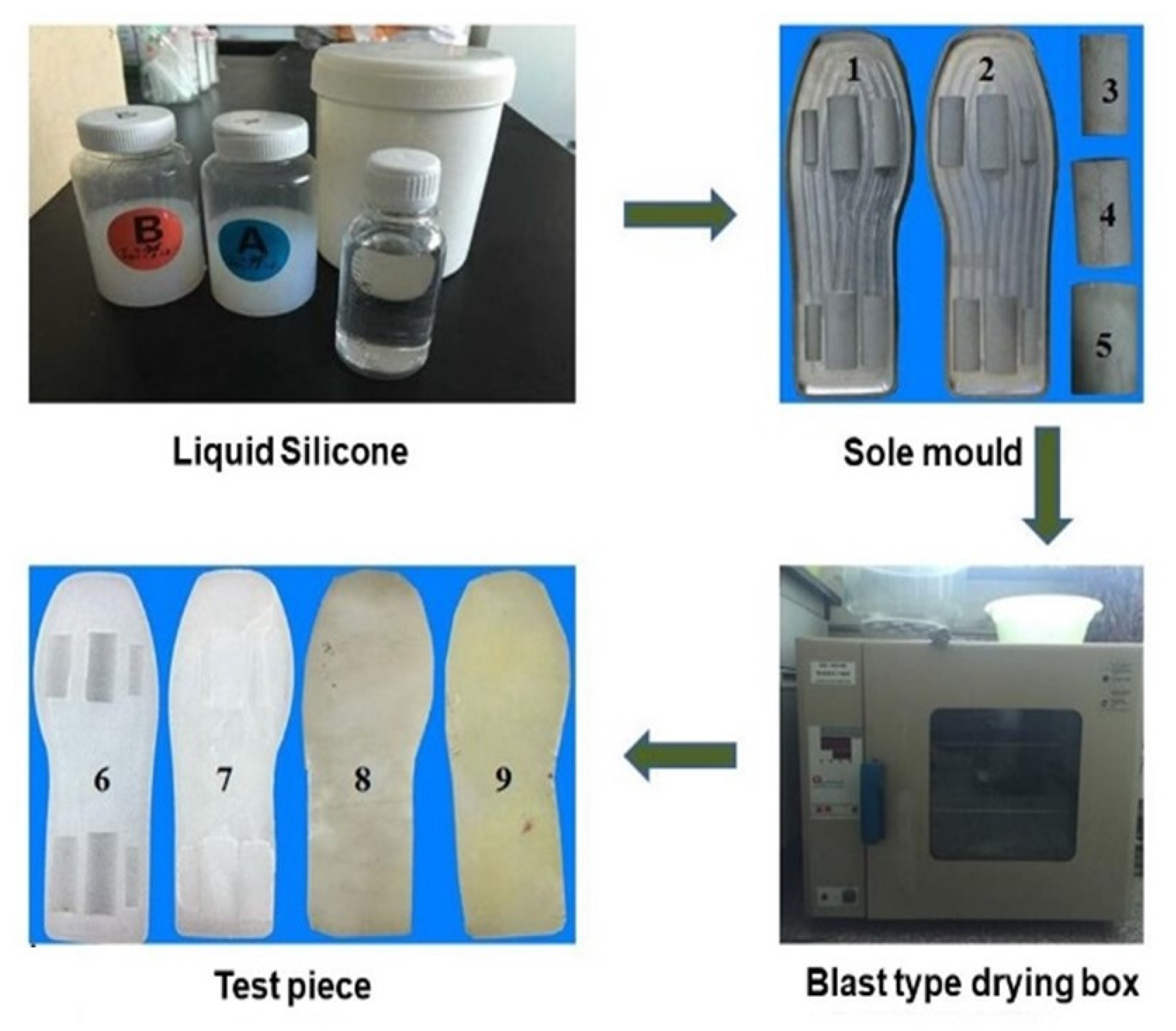
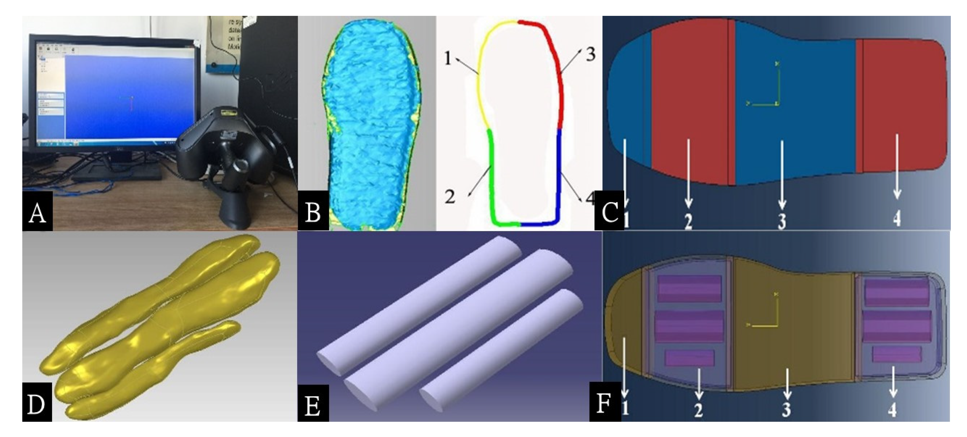
2.3. Bionic Engineering Procedures

The profile of a midsole was scanned using a Handyscan 3D laser scanner system (Creaform, Levis, QC, Canada) with a 40-mm depth of field, 50-μm resolution, and 0.02-mm volumetric accuracy in three directions. The sampling rate was set to 25,000 Hz to obtain the corresponding curve equations. The shape of the midsole area was simplified based on the measurement results of the ostrich toe pad, which were used for the forefoot, and the heel area design was simplified into elliptical, cylindrically shaped structures [18]. The conventional midsoles were formed according the ostrich foot skin structure, and the bionic midsoles were made according the ostrich foot toe pad complex structure (cushioning, fascial, and skin structure) in the forefoot and heel area. When comparing the two midsoles, the conventional midsole had a greater hardness (66 C), and the bionic midsole was softer (46 C).
The test midsoles were manufactured in silicone material. The raw material was mixed with a curing agent in a predetermined ratio, poured into the mold at a given spot, and then placed in a blast air oven for curing. After that, the products were stripped from the molds, and the midsole was finally assembled. Figure 2 shows the process of midsole manufacturing.

2.4. Participants

Three male adults were recruited to participate in the foot pressure experiment (mean age: 24.7 ± 0.9 years; body mass: 71.5.3 ± 6.5 kg; height: 1.79 ± 0.35 m; body mass index: 22.2 ± 1.6 kg/m2; shoe size: 42). They were recreational runners and all rearfoot strikers. All subjects were free from lower extremity injuries for 6 months prior to testing, and written consent was obtained before testing. All procedures carried out in this study were approved by the Institutional Animal Care and Use Committee (IACUC) of Jilin University. The subjects were tested under the conditions of constant-speed walking (2 km/h) and brisk walking (4 km/h).

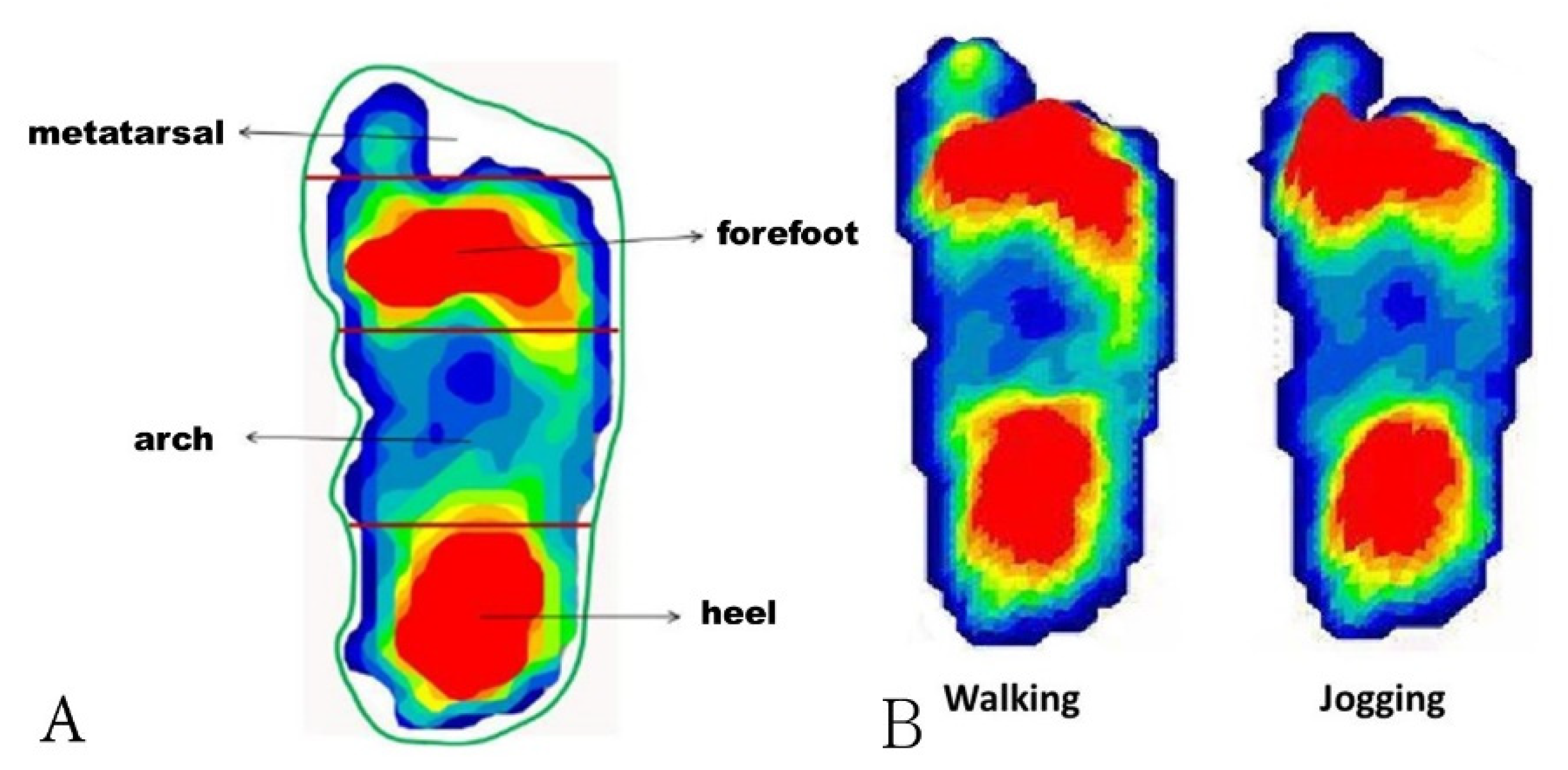
2.5. Plantar Pressure Test Procedures

The F-Scan (100 Hz, Tekscan, Inc., South Boston, MA, USA) was employed to collect plantar pressure data when the participants were wearing shoes with either the bionic or conventional midsole. The participants performed 5 trials in each experimental condition (i.e., bionic midsoles walking; bionic midsoles brisk walking; conventional midsoles walking; and conventional midsoles brisk walking) in a randomized order. A stopwatch was used to confirm the walking or brisk walking velocity. Four planta areas were analyzed: the metatarsal, forefoot, arch, and heel areas (Figure 3). In total, 8 s of walking or brisk walking data were collected. The peak pressure, peak force, and average pressure in the forefoot and heel areas, as well as the pressure–time and force–time integrals [19,20,21,22], were collected.

3. Results and Discussion

3.1. Ostrich Foot Dissection

After dissection, the three structural elements of an ostrich foot (Figure 4A) were confirmed: the highly elastic yellow cushioning toe pad structure, the fascial structure, and the outermost skin structure (Figure 4B). The elastic structures were assumed to buffer the counter reaction force exerted by the ground when the ostrich runs at high speed and act as a protective layer for the ostrich foot. Additionally, the elastic structures were assumed to store a certain amount of energy, which was then released when the foot was above the ground. This reduces the ostrich’s energy expenditure during running. Morphology analysis of the ostrich’s cushioning toe pad was performed through observation of a thin paraffin-embedded section. The corresponding image at 100× magnification is presented in Figure 4C. The irregular and semitransparent aggregations shown in Figure 4C are fat cells. The image indicates that the fat cells in the toe pads are clustered, and these clusters play a critical role in energy storage and shock absorption. The measurement results of the cushioning toe pad structures of the ostrich feet are shown in Table 2 and Table 3.
The animal body’s composition is divided into soft tissue and hard tissue. Except for the teeth and bones, most body structures are classified as soft tissue, such as cartilage, skin, muscle, fat, tendons, and ligaments. Due to the higher hardness and convenience in machining, bones are often used for bionic and other related biology research [23,24,25]. In contrast to bones, soft tissue is difficult to shape, which makes it much more difficult to test, leading to less research in this area. However, in the past few years, advances in measurement technology have led to significant progress in soft tissue biomechanics [26]. Nevertheless, there has been little research on the soft tissue biomechanics of ostriches. Our research measures the toe pads of ostrich feet and analyzes the structure and properties based on biomaterials and biomechanics.

3.2. Bionic Engineering Procedures

The forefoot and heel areas of the bionic midsole were designed to comprise three components, namely the internal shock absorption structure, the middle transitioning structure, and the outer pressure-bearing structure. In particular, the thickness ratio of the transitioning structure to the pressure-bearing structure was 1:1. The shock absorption structures were installed in the forefoot and heel area (Figure 5C,F, lines 2, 4), with each structure including three shock absorption components (Figure 5E). The proportions of the three shock absorption components were as follows: width dimensions of 3:6:5, thickness dimensions of 5:8:7, and length dimensions of 10:14:13. The internal shock absorption structure, middle transitioning structure, and outer pressure-bearing structure each comprised silicone material with different levels of hardness. The Shore hardness ratio for the three structures was 6:8:1. The preliminary constructed bionic shoe sole model is displayed in Figure 5.

3.3. Physics Tests and Numerical Simulations

3.3.1. Finite Element Method

The results showed that the energy absorption ability was increased with the bionic midsole compared with the conventional sole in the forefoot and heel areas. In the forefoot area, the energy absorbed increased by 22.1–24.3% when the impact energy was increased from 2.35 to 5.88 J, indicating that the extra impact energy absorbed by the bionic midsole was 14.4–21.0% greater (Figure 6A). In the heel area, the energy absorbed increased by 22.1–24.3% with the bionic midsole, which indicated that the extra impact energy absorbed was 15.8–20.4% greater than with the conventional sole (Figure 6B). In summary, the results indicate that the bionic sole had a superior shock absorption ability compared with the conventional sole and would thus be more capable of protecting the feet during exercise.

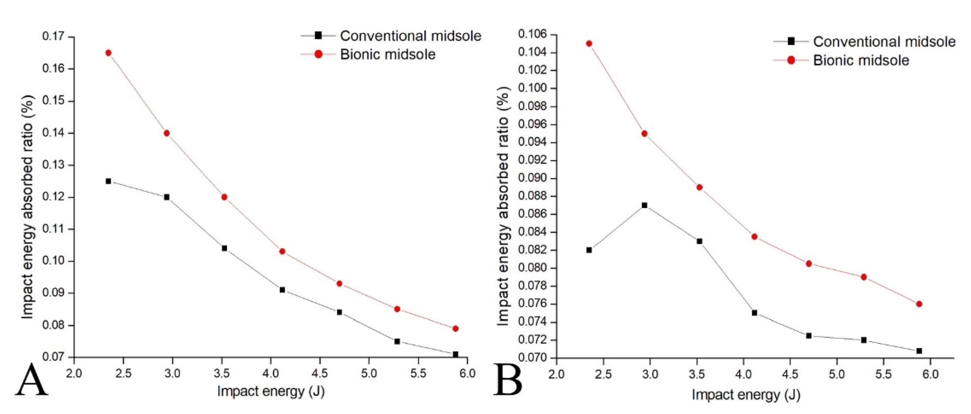
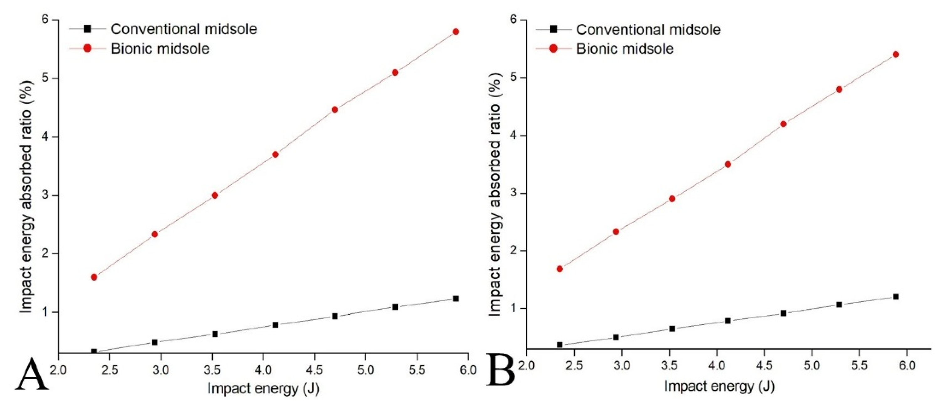
3.3.2. Impact Experiments

When the hammer drop height was increased from 4 to 10 cm (corresponding to an impact energy increase from 2.35 to 5.88 J), the results for the bionic midsole showed that the energy absorbed increased by 7.15–12.49% in the forefoot area, indicating that the extra impact energy absorbed was 7.92–16.88% greater than that for the conventional sole (Figure 7A). In the heel area, the energy absorbed increased by 7.06–8.14% with the bionic midsole, indicating that the extra impact energy absorbed was 7.59–10.45% greater than that with the conventional sole (Figure 7B). These results indicate that the bionic midsole can sustain greater impact and absorb more impact energy than the conventional midsole, thus exhibiting superior shock absorption.
The advantages of the bionic midsole were verified through physics tests and numerical simulations in this research, although discrepancies between the simulation and physics test results were found. These discrepancies may be due to experimental limitations because the impact tests were performed manually, and the test machine may also have had some limitations, such as in the hammer falling distance, frictional force between the hammer and test platform, initial tension of the elastic rope, and direction control of the impact hammer. These influenced the testing results. In addition, the input parameters of the biomaterials were somewhat different, which also influenced the testing results. However, when comparing the simulations and physics tests, the trend in the results was consistent and indicated that the bionic midsole had better shock absorption performance.

3.3.3. Plantar Pressure Tests

The results show that the highest plantar pressure was in the forefoot area under all conditions, and the peak plantar pressure was lower with the bionic midsole shoe. Except for the arch area, the peak plantar pressure in the different plantar areas was lower for the bionic midsole than for the conventional midsole. Our results show that during walking and brisk walking with the bionic midsole shoe, the peak pressure in the forefoot area decreased by 10.59% and 8.35%, respectively, and that in the heel area, it decreased by 12.27% and 6.04%, respectively, while the peak force in the forefoot area decreased by 10.31% and 8.62%, respectively, and that in the heel area decreased by 16.03% and 14.47%, respectively. The average pressure in the forefoot area during walking and brisk walking decreased by 7.95% and 7.88%, respectively, and that in the heel area decreased by 8.92% and 7.36%, respectively, while the pressure–time integral in the forefoot area decreased by 4.23% and 4.06%, respectively, and that in the heel area decreased by 10.58% and 10.29%, respectively. The force–time integral in the forefoot area during walking and brisk walking decreased by 12.66% and 6.91%, respectively, and that in the heel area decreased by 3.06% and 5.72%, respectively.
Plantar pressure is a key factor in evaluating shoe comfort which also represents the shock absorption ability of sports shoes. Such sports shoes with better shock absorption function show decreased plantar pressure and impact energy transfer to the body and joints [27]; otherwise, a larger impact force additionally increases the injury risk and makes wearing shoes feel uncomfortable [13,14,28]. Higher plantar pressure in the forefoot during running may be related to metatarsal injuries [29], and evenly distributed plantar pressure is beneficial for foot health [2,11]. The results show that the bionic midsole did show a better shock absorption ability compared with the conventional midsole, especially in the forefoot and heel areas. During the walking and brisk walking tasks, the bionic midsole showed better shock absorption performance in plantar pressure, which indicated that the bionic midsole would likely be more comfortable. For the higher impact force in forefoot area, we believe this was attributed to the reaction force during the push-off phase. The bionic midsole decreased the push-off force during the walking tasks, which needs further research to investigate the influence on exercise or sports. The present research provides a new design idea via the ostrich toe pad structure and the development of a shoe midsole to better protect the feet during daily physical activity. This represents a considerable advance in shoe manufacturing.
The pressure–time integral and force–time integral indicate the cumulative situation of plantar loading, presenting the energy consumption of foot strikes during walking and brisk walking. Exorbitant integral values indicate the poor shock absorption ability of the midsoles, increasing the risk of potential injuries in lower extremity skeletal tissues [30]. Munro et al. (1987) [31] indicated that during running, the higher force loading in the forefoot that makes the impact force swiftly rise to its peak is also believed to have a connection to running-related injuries [32]. A higher contact area or better shock absorption by the midsole could help runners to temporarily avoid lower extremity overload risks [33]. Our results indicate that the bionic midsole had better shock-absorption of the planta pressure compared with the conventional midsole. A runner’s joints may adapt to the stimulation of internal and external forces [33], but the adaptation may not be able to prevent injury factors for a prolonged period. Whether a bionic shock absorption midsole is better for sustained physical activity requires further investigation.
There are some limitations in the present research that should be mentioned. First, there were only three subjects in the plantar pressure test, which expressed only a preliminary achievement of bionic midsole design. Our research group needs to further optimize the bionic midsole. Deep learning analysis [34] to predict the distribution of the impact force on the feet may be applied, which can assist in various other shoe designs. Secondly, the foot type was not classified in terms of the arch heights, and how they affected the apportioning of plantar pressure was unknown.

4. Conclusions

In the present study, we used an innovative approach to develop new products through bionic engineering, with inspiration drawn from the high cushioning quality of ostrich toe pads when ostriches run at high speed. This was employed as a biological prototype and applied for the design of a midsole. Specifically, the critical cushioning characteristics of the ostrich toe pad were identified, and a bionic shock absorption midsole was designed according to the principles of bionic engineering. Additionally, we used plantar pressure measurement to test the midsole performance, which has value for practical applications. We believe that the results of this study could be a determinant reference for researchers that promotes the shoe manufacturing industry and provides new sustainability research directions for bionic sports equipment.

Author Contributions

Conceptualization, R.Z. and G.-L.Y.; Data curation, D.-C.W.; Formal analysis, H.-T.W. and D.-C.W.; Investigation, H.-B.Y.; Methodology, H.-T.W. and D.-C.W.; Resources, R.Z.; Software, G.-L.Y.; Validation, H.-B.Y. and J.-L.H. Writing—original draft, H.-T.W.; Writing—review & editing, W.-H.T. All authors have read and agreed to the published version of the manuscript.

Funding

This research received no external funding.

Institutional Review Board Statement

Not applicable.

Informed Consent Statement

Informed consent was obtained from all subjects involved in the study.

Data Availability Statement

The data presented in this study are available on request from the corresponding author.

Acknowledgments

The authors are grateful for the financial support from the National Natural Science Foundation of China (No.51675221), Science and Technology Program of Quanzhou (No.2021CT0010), and Education Research Project (JAT190544, JAT190545) of Fujian. The authors also acknowledge the support of the Fujian Provincial Key Laboratory of Data-Intensive Computing, Fujian University Laboratory of Intelligent Computing and Information Processing, and Fujian Provincial Big Data Research Institute of Intelligent Manufacturing.

Conflicts of Interest

The authors declare no conflict of interest.

References

  1. Lieberman, D.E.; Venkadesan, M.; Werbel, W.A.; Werbel, W.A.; Daoud, A.I.; D’Andrea, S.; Davis, I.S.; Mang’Eni, R.O.; Pitsiladis, Y. Foot strike patterns and collision forces in habitually barefoot versus shod runners. Nature 2010, 463, 531–535. [Google Scholar] [CrossRef]
  2. Xu, X.; Zhang, C.; Derazkola, H.A.; Demiral, M.; Zain, A.M.; Khan, A. UFSW tool pin profile effects on properties of aluminium-steel joint. Vacuum 2021, 192, 110460. [Google Scholar]
  3. Xu, X.; Zhang, C.; Derazkola, H.A.; Demiral, M.A.; Khan, A. Dispersion of waves characteristics of laminated composite nanoplate. Steel Compos. Struct. 2021, 40, 355–367. [Google Scholar]
  4. Gupta, N.A. functionally graded syntactic foam material for high energy absorption under compression. Mater. Lett. 2007, 61, 979–982. [Google Scholar] [CrossRef]
  5. Zhang, S.; Clowers, K.; Kohstall, C.; Yu, Y.J. Effects of various midsole densities of basketball shoes on impact attenuation during landing activities. J. Appl. Biomech. 2005, 21, 3–17. [Google Scholar] [CrossRef] [PubMed]
  6. Beynnon, B.D.; Vacek, P.M.; Murphy, D.; Paller, D. First-time inversion ankle ligament trauma: The effects of sex, level of competition, and sport on the incidence of injury. Am. J. Sports Med. 2005, 33, 1485–1491. [Google Scholar] [CrossRef] [PubMed]
  7. Rome, K.; Frecklington, M.; McNair, P.; Gow, P.; Dalbeth, N. Foot pain, impairment, and disability in patients with acute gout flares: A prospective observational study. Arthritis Care. Res. 2012, 64, 384–388. [Google Scholar] [CrossRef] [PubMed] [Green Version]
  8. Li, Y.; Leong, K.F.; Gu, Y. Construction and finite element analysis of a coupled finite element model of foot and barefoot running footwear. Proc. Inst. Mech. Eng. Part J. Sport Eng. Technol. 2018, 233, 101–109. [Google Scholar] [CrossRef]
  9. Sofla, F.S.; Hadadi, M.; Rezaei, I.; Azhdari, N.; Sobhani, S. The effect of the combination of whole body vibration and shoe with an unstable surface in chronic ankle instability treatment: A randomized clinical trial. BMC Sports Sci. Med. Rehab. 2021, 13, 28. [Google Scholar]
  10. Wong, P.L.; Chamari, K.; Mao, D.W.; Wisloff, U.; Hong, Y. Higher plantar pressure on the medial side in four soccer-related movements. Br. J. Sports Med. 2007, 41, 93–100. [Google Scholar]
  11. Guettler, J.H.; Ruskan, G.J.; Bytomski, J.R.; Brown, C.R.; Richardson, J.K.; Moorman, C.T. Fifth metatarsal stress fractures in elite basketball players: Evaluation of force acting on the fifth metatarsal. Am. J. Orthop. 2006, 35, 532–536. [Google Scholar]
  12. Cui, L. Analyzing the functional requirements of the sole of basketball shoes based on plantar pressure distribution. J. Shanxi Univ. Sci. Technol. 2010, 28, 311–315. [Google Scholar]
  13. Tang, Z.; Zhao, G.; Ouyang, T. Two-phase deep learning model for short-term wind direction forecasting. Renew. Energy. 2021, 173, 1005–1016. [Google Scholar] [CrossRef]
  14. Chiu, H.T.; Shiang, T.Y. Effects of insoles and additional shock absorption foam on the cushioning properties of sport shoes. J. Appl. Biomech. 2007, 23, 119–127. [Google Scholar] [CrossRef] [Green Version]
  15. Wei, Z.; Zhang, Z.; Jiang, J.; Zhang, Y.; Wang, L. Comparison of plantar loads among runners with different strike patterns. J. Sports Sci. 2019, 37, 2152–2158. [Google Scholar] [CrossRef]
  16. Ali, M.; Nazir, A.; Jeng, J.Y. Mechanical performance of additive manufactured shoe midsole designed using variable-dimension helical springs. Int. J. Adv. Manuf. Technol. 2020, 111, 3273–3292. [Google Scholar] [CrossRef]
  17. Wei, Q. An Exploration of the Relationship between the Sole Structure of Basketball Shoes and Its Shock Absorption Properties. Master’s Thesis, Shanxi University of Science & Technology, Shanxi, China, 2012. [Google Scholar]
  18. Ye, S. The dynamic foot pressure distribution of university students during jogging. Chin. J. Tissue Eng. Res. 2009, 13, 9109–9112. [Google Scholar]
  19. Zhao, C. Design and Study on Jogging Shoes Cushioned Insoles. Master’s Thesis, Shanxi University of Science & Technology, Shanxi, China, 2013. [Google Scholar]
  20. Wu, J.; Li, J.S. Research progress in the biomechanics of human gait during walking. Chin. J. Sports Med. 2002, 21, 305–307. [Google Scholar]
  21. Yu, H.B.; Zeng, Q.S.; Zheng, Z.Y.; Pan, Z.S.; Yang, L. Relationship between foot presure and subjective comfort of shoes during 20 km running. J. Beijing Sport Univ. 2018, 41, 70–75. [Google Scholar]
  22. Liu, L. Effects on the Shoe Sole’s Shock Absorption Structures on the Shock Absorption System of Human Feet. Master’s Thesis, Shanxi University of Science & Technology, Shanxi, China, 2015. [Google Scholar]
  23. Gosman, J.H.; Hubbell, Z.R.; Shaw, C.N.; Ryan, T.M. Development of cortical bone geometry in the human femoral and tibial diaphysis. Anat. Rec. 2013, 296, 774–787. [Google Scholar] [CrossRef] [PubMed]
  24. Brassey, C.A.; Margetts, L.; Kitchener, A.C.; Withers, P.J.; Manning, P.L.; Sellers, W.I. Finite element modelling versus classic beam theory: Comparing methods for stress estimation in a morphologically diverse sample of vertebrate long bones. J. R. Soc. Interface 2013, 10, 20120823. [Google Scholar] [CrossRef] [PubMed] [Green Version]
  25. Main, R.P.; Lynch, M.E.; Mc, V.D.M. In vivo tibial stiffness is maintained by whole bone morphology and cross-sectional geometry in growing female mice. J. Biomech. 2010, 43, 2689–2694. [Google Scholar] [CrossRef] [PubMed] [Green Version]
  26. Shergold, O.A.; Fleck, N.A.; Radford, D. The uniaxial stress versus strain response of pig skin and silicone rubber at low and high strain rates. Int. J. Impact Eng. 2006, 32, 1384–1402. [Google Scholar] [CrossRef]
  27. Nigg, B.M.; Stefanyshyn, D.; Cole, G.; Miller, J. The effect of material characteristics of shoe soles on muscle activation and energy aspects during running. J. Biomech. 2003, 36, 569–575. [Google Scholar] [CrossRef]
  28. Kernozek, T.W.; Vannatta, C.N.; Gheidi, N.; Kraus, S.; Aminaka, N. Plantar loading changes with alterations in foot strike patterns during a single session in habitual rear foot strike female runners. Phys. Ther. Sport 2016, 18, 32–37. [Google Scholar] [CrossRef]
  29. Almeida, M.O.; Davis, I.S.; Lopes, A.D. Biomechanical differences of foot-strike patterns during running: A systematic review with meta-analysis. J. Orthop. Sports Phys. Ther. 2015, 45, 738–755. [Google Scholar] [CrossRef] [Green Version]
  30. Munro, C.F.; Miller, D.I.; Fuglevand, A.J. Ground reaction forces in running: A reexamination. J. Biomech. 1987, 20, 147–155. [Google Scholar] [CrossRef]
  31. Zadpoor, A.A.; Nikooyan, A.A. The relationship between lower-extremity stress fractures and the ground reaction force: A systematic review. Clin. Biomech. 2011, 26, 23–28. [Google Scholar] [CrossRef]
  32. Daoud, A.I.; Geissler, G.J.; Wang, F.; Saretsky, J.; Daoud, Y.A.; Lieberman, D.E. Foot strike and injury rates in endurance runners: A retrospective study. Med. Sci. Sports Exerc. 2012, 44, 1325–1334. [Google Scholar] [CrossRef] [PubMed] [Green Version]
  33. Schaller, N.U. Birds on the run: What makes ostriches so fast? Sci. School 2011, 21, 12–16. [Google Scholar]
  34. Lamas, L.P.; Main, R.P.; Hutchinson, J.R. Ontogenetic scaling patterns and functional anatomy of the pelvic limb musculature in emus (Dromaius novaehollandiae). PeerJ 2014, 2, e716. [Google Scholar] [CrossRef] [PubMed] [Green Version]
Figure 1. The impact experiment set-up (A). Note: 1, 2 = high speed camera, 3 = ground, 4 = test object, 5 = impact head, 6 = hammer (6 kg), 7 = securing nut, 8 = hand ring, 9 = computer, 10 = elastic rope, and 11 and 12 = marker set (B).
Applsci 11 09679 g001
Figure 2. Manufacturing process of the silicone midsole. Note: 1, 2 = middle-layer mold of the midsole; 3, 4, 5 = inner-layer mold of the midsole; 6 = end product of middle-layer construction; 7 = combination of the middle layer and inner layer; 8 = conventional midsole; and 9 = bionic midsole.
Applsci 11 09679 g002
Figure 3. Definitions of the plantar pressure areas (A) and the 3D picture of walking or brisk walking (B).
Applsci 11 09679 g003
Figure 4. Observation of an ostrich’s foot pad. (A) Appearance of the ostrich’s foot pad. (B) Sectional view of the ostrich’s foot pad. Note: 1–3 = elastic yellow cushioning toe pad structure, 4 = fascial structure, and 5 = skin structure. (C) Image of a thin paraffin-embedded section.
Applsci 11 09679 g004
Figure 5. Construction of a bionic midsole model, showing (A) 3D laser scanning; (B) extraction of the profile curves; (C) midsole segmentation; (D) internal cushioning toe pads; (E) simplified internal structures; and (F) the final bionic midsole model. Note that in (C,F), 1 = metatarsal area, 2 = forefoot area, 3 = arch area, and 4 = heel area.
Applsci 11 09679 g005
Figure 6. Energy absorption performance of the forefoot (A) and heel (B) in bionic and conventional soles in numerical simulations.
Applsci 11 09679 g006
Figure 7. The energy absorption performance of the forefoot (A) and heel (B) in bionic and conventional soles.
Applsci 11 09679 g007
Table 1. The parameters of the bionic midsole finite element method simulations.
ModelDensity ρ (g/mm3)Elastic Modulus E (MPa)Poisson’s Ratio γ
Cushioning structure7.30 × 10−43.80.47
Fascial structure7.45 × 10−46.40.4
Skin structure8.07 × 10−48.30.4
Loading3.56 × 10−1Rigid body--
Ground support7.85 × 10−3Rigid body--
Table 2. Descriptive data from the survey of toe pads, based on mean (M) and standard deviation (SD) values.
Toe PadLength (mm)
M ± SD
Width (mm)
M ± SD
Thickness (mm)
M ± SD
Mass (g)
M ± SD
Density ρ (g/mm3)
M ± SD
Cushioning structure----7.57 ± 0.230.35 ± 0.027.30 × 10−4 ± 2.11 × 10⁻⁵
Fascial structure35.23 ± 0.214.99 ± 0.041.71 ± 0.030.23 ± 0.017.45 × 10−4 ± 1.57 × 10⁻⁵
Skin structure30.45 ± 0.297.24 ± 0.141.87 ± 0.060.33 ± 0.028.07×10−4 ± 3.15×10⁻⁵
Table 3. Hardness and elasticity data from the survey of toe pad structures.
Toe Pad Hardness (Shore C)Elastic Modulus E (MPa)
Cushioning structure31.8 ± 1.93.77 ± 2.33
Fascial structure41.9 ± 1.96.38 ± 1.37
Skin structure65.8 ± 2.38.30 ± 1.76
Publisher’s Note: MDPI stays neutral with regard to jurisdictional claims in published maps and institutional affiliations.

