Abstract
Renewable and sustainable energy sources can play an important role in meeting the world’s energy needs and also in addressing environmental challenges such as global warming and climate change. Geothermal well-doublet systems can produce both electrical and thermal energy through extracting heat from hot-water aquifers. In this paper, we examine some potential challenges associated with the operation of well-doublet systems, including heat conductivity, chemical, and mechanical issues. In these systems, geomechanics issues such as thermal short-circuiting and induced seismicity arise from temperature and pressure change impacts on the stress state in stiff rocks and fluid flow in fractured rock masses. Coupled chemical processes also can cause fluid channeling or formation and tubular goods plugging (scaling) with precipitates. Mechanical and chemical disequilibrium conditions lead to increased production uncertainties; hence risk, and therefore coupled geo-risk assessments and optimization analyses are needed for comparative commercialization evaluations among different sites. The challenges related to heat transfer processes are also examined. These studies can help better understand the issues that may arise during the operation of geothermal well-doublet systems and improve their effectiveness, subsequently reducing associated costs and risks.
1. Introduction
Energy is an essential and unavoidable need in today’s world and has played a crucial role in human civilization [1,2,3]; demand is increasing, with the principal reasons being the world’s growing population and the general desire for an improved life quality [4,5,6,7]. Fossil fuels comprise over 80% of primary energy sources [8,9], but effects arising from greenhouse gas (GHG) emissions and air pollution, leading to environmental degradation, global warming, and climate change, are of increasing concern [10,11,12,13]. Geothermal energy, a sustainable and green source, is now meeting some communities’ thermal and electrical energy requirements [10,11,14]; it can be reliable in the long term, is environmentally friendly [7,15], and could help reduce fossil fuel consumption [8,9].
1.1. Geothermal Energy Characteristics
Geothermal energy can be categorized as volcanic, sedimentary, geo-pressured, hot dry rock (HDR) or enhanced (engineered) geothermal (EG), or shallow [7,16]. It should be noted that shallow geothermal energy can be defined in terms of shallow geothermal systems based on ground-source heat pumps that are installed at depths less than 500 m [17]. Geothermal resources can also be divided into three groups based on reservoir fluid temperatures [18]: low, medium, and high enthalpy resources. Their common point is accessing natural underground heat sources, whether from dry steam reservoirs (electrical power) to the normal warmth of deeply buried rocks and their interstitial fluids (district heating). Although such energy is often classified as renewable because of the continuous heat flux in the Earth’s crust, realistically, the heat renewal rate (≈100–1000 years) is far slower than the design life-span of a commercial project (25–40 years) unless strong hot fluid recharge is occurring. The extraction system and energy rate must be compatible with project life needs [19], and in most cases, from an engineering project life-span definition, geothermal energy is not renewable. In other words, the life-span of any commercial geothermal project is strongly dependent on the geological characteristics of the resources and the appropriate sizing of the power/heat plant.
Once a spatially limited volume of the reservoir has been “heat mined,” the heat recharge rate from crustal thermal conduction is too slow to sustain commercial use unless an external heat source is being used to “recharge” the reservoir heat content. However, heat is everywhere available at depth, so the project design basis should include continued access to previously unmined heat (i.e., drilling more wells on an ongoing basis or recharging the repository heat).
Economically, the amount of energy available and the rate of energy production are essential criteria for project performance. Although initial reservoir temperature (To) is the dominant variable, which defines the energy content, the amount of energy production is also related to the reservoir pressure—P (natural or maintained if fluid injection is being exploited). Overall, a higher temperature and pressure reservoir is better [8], but there are a variety of other variables such as reservoir volume, permeability, porosity, storativity, and natural recharge rate (if any) that are important to the commercially viable project duration. Site assessment factors include reservoir geometry (depth, thickness, and lateral extent), flow characteristics (permeability heterogeneity, fracture vs. porous media flow, channels, etc.), the potential for natural recharge, the tectonic state and stress field, and structural geology factors [20].
Whether a reservoir is open or closed to natural high-temperature fluid influx impacts life-span assessment: in a closed system with a constant production and no injection, reservoir pressure decreases continuously, requiring aggressive pumping or leading to a rapid loss of water production, although the rock mass may remain at high temperature. These systems may be considered for re-injection operations, as a closed sedimentary geothermal formation can be developed with a well-doublet (or multi-well) system. In contrast, an open system has a more stable pressure but may require flow rate management and assessment of the recharge rate and energy content (production temperature Tin) to assure commercial viability [19]. An open system with an “infinite” flow capacity can be exploited with single pumped production wells, but the geothermal fluids have to be disposed of in the subsurface into suitable (likely shallower) saline aquifers.
In the current paper, we use the increasingly common term “SedHeat” (sedimentary heat) for systems where warm and hot fluids are being exploited from sedimentary rocks of sufficient permeability and porosity at depth [21,22], in contrast to steam systems (wet or dry), or to geothermal heat found in low-permeability rock masses (granites, shales, tight volcanic or metamorphic rocks, etc. [23,24]).
1.2. The Geothermal Doublet
The well-doublet design (Figure 1) is the simplest approach to energy extraction in a closed or limited recharge SedHeat system, whether it is a deep liquid reservoir or a shallow ground-source heat pump system using an unconfined aquifer. From one well equipped with a lifting pump, the SedHeat aquifer supplies hot-water from which energy is extracted by a heat exchanger to be sent for power generation or direct heat use. Cooled geofluid re-injection takes place into another well placed at an optimum distance designed to meet the project’s desired power profile (power = electrical and heat energy rate) [25] and sustain flow. The maximum energy rate (work or power) available, ignoring all of the minor hydraulic losses (pumps, fitting, etc.) and irrecoverable heat losses, is
where is the energy rate (power) in J/s, ΔT = (Tin –Tout) in K, is the flow rate in kg/s, and cp is the fluid heat capacity in J/kg·K. Tin and Tout (units of K) refer to the inlet and exit temperatures in the energy (electricity + heat) extraction system, likely a heat exchanger. The fluid involved may be the natural fluids in the case of SedHeat development, or in the case of EG systems, it is likely to be an introduced fluid such as water or supercritical CO2 [26].
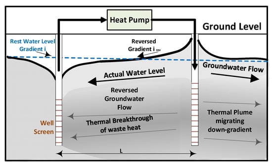
Figure 1.
Schematic illustration of a typical shallow geothermal well-doublet system with a single primary loop, no heat exchanger, in an unconfined aquifer (modified from [27]).
Specifically, Tin is not the original reservoir To; it is the temperature at the surface going into the energy system (the heat exchanger between the primary loop and the secondary power/heat system loop). It will eventually change with time as cool injected fluids begin to impinge upon the production well. Nor is Tout equal to the ambient temperature; Tout will always be higher because of thermodynamic constraints. Unextracted heat in the primary loop fluid is returned to the reservoir through fluid re-injection; if there are low-grade waste heat sources to increase Tout through a downstream heat exchanger, the project life may be extended, and the low-grade heat exploited. The parameter is mainly a function of the aquifer’s permeability, thickness, and layering, the amount of energy desired or achievable, the aquifer’s thermal properties and heat recovery time [8], and several secondary factors. A reasonable value for cp is 4180 J/kg·K for pure freshwater, somewhat different for geofluids of different salinities. For fluids such as supercritical CO2, different specific heats, fluid densities, and viscosities must be used, and these may be quite sensitive to P and T, leading to additional non-linear effects in modeling heat extraction.
Using a recirculating well-doublet in a binary geothermal system means that remnant useable heat in the geofluid (e.g., 50–70 °C) is reinjected after electrical power generation, but if space heating is needed, additional heat can be stripped from the fluids, lowering re-injection T. Furthermore, coupling a deep doublet with a shallow ground-source heat pump system allows shallow seasonal heat storage and recovery (a thermal repository) and leads to higher efficiency and lower fossil-fuel use where there is a cooling deficiency in the summer [28], as in northern climates. Using a deep multi-well system allows injection/production strategies to be devised to maximize the system’s value, while also exploiting the shallow heat repository in the winter when high heat demand exists. The design of such a system depends on the estimated power/thermal energy profiles for the year, combined with a safety factor, and noting that design in Canada (for example) must be to meet November–March energy needs.
If natural or planned thermal recharge is rapid enough, considering the recovery time of the system and the injection/production strategy, a geothermal SedHeat system might approach being a renewable and sustainable energy source [25]. In other words, the deep system life-span can be extended by designing for slow energy extraction relative to the system volume, re-injection of unused heat, extracting value from sources of waste heat, and even using seasonal solar and excess wind power to recharge the thermal repository. It is possible to prolong the system’s energy provision profile by keeping heat extraction at a sustainable level or by designing it initially so that the combined electrical power and heat outputs extend the long-term utility of the project. In addition, it may be possible for a SedHeat system to generate power and heat for 20–30 years, but in the later life stages when the Tin is degraded, and power generation is suffering, the original wells may be operated for heat production, but new sources developed for power generation. In this scenario, given that the capital investment has been recovered, the initial wellbore system can be economically continued for heat provision only. Geothermal energy developed in this way is inherently sustainable because of the huge masses of warm rock in the crust and within reasonable drilling depth. SedHeat is, of course, limited to sedimentary basins, but other technologies are being explored for low permeability rock masses such as crystalline rocks.
1.3. Disequilibrium Processes
Leaving aside initial geological conditions, the causes of disequilibrium that result in an inadequate or a drop in Ė are based on mechanical, geochemical, and heat conductivity conditions and issues, ranging from processes within the reservoir itself (flow, mineral precipitation, channelling, etc.) to the access and energy systems (wells, pumps, heat exchangers, surface tubing insulation, etc.).
- Chemical condition:
- Well integrity
- Induced primary loop corrosion (e.g., acidic waters corroding steel), both internal and external to the well casing, potentially exacerbated by high temperatures and electrochemical corrosion
- Primary loop internal mineral precipitation—scaling (increasing pipe friction losses)
- Reservoir condition
- Mineral and rock dissolution (e.g., dissolving of gypsum) or other alteration (e.g., induced clay mineral swelling from changing geochemistry).
- Microbiologically induced pore blockage or corrosion through the generation of biofilms or weak organic acids that act on minerals (mainly carbonates)
- Chemical changes and processes induced by flow, ΔT, and ΔP, leading to solubility gradients that trigger dissolution and precipitation
- Flushing of pipe corrosion and precipitated mineral particles into the reservoir, generating blockage of flow paths
- Mechanical condition:
- Rock mechanics issues: stress-strain (σ–ε) processes and their effects on porosity and permeability, particularly in systems dominated by fracture flow and susceptible to thermoelastic impacts
- The transition from laminar to turbulent flow regime near the well at high flow rates (short-term impacts on production and injection phases)
- Heat conductivity and recovery condition:
- Pumping rates with respect to produced fluid temperature changes and well field life-span
- Alterations of efficiency associated with thermal viscosity changes
- Interference with the natural thermal recharge system in the deep aquifer
- Channeling of flow, fracture dilation through cooling leading to flow short-circuiting, and related thermoelastic effects that lead to reductions in the subsurface heat exchange area
The long-term result of disequilibrium processes in the reservoir may be evidenced as pore throat blockage and fracture aperture reduction, leading to reservoir fluid conductivity changes, including permeability reduction, channeling of flow, and related processes. If these changes are properly understood and predicted, project planning becomes easier, allowing answers to questions related to the drilling of new wells, workover scheduling for impaired wells, adding more injection or production wells, developing a new productive horizon (deeper or shallower), changing the electricity/heat output ratio, and so on.
To optimize energy production, increase the project life-time, enhance the fiscal outcomes and minimize environmental impacts, many issues associated with heat extraction from a geothermal well-doublet system need to be considered; these issues are addressed in this study.
2. Chemical Condition
Questions arise as to whether deep geothermal systems can be preserved while retaining their production quality, achieving the desired Ė over the project life. We note that the best outcome is keeping Ė constant, but a project can also be designed on the basis of a gradually declining Ė, as long as it can be realistically predicted. Answers depend on water-rock reactions and reservoir condition changes over the project life, as chemical reactions may cause flow-path changes (precipitation in flow paths) and potentially alter the heat transfer efficiency between rock and water. To predict changes in permeability or fracture conductivity, chemical effects need to be investigated for the project’s expected life-span [29].
2.1. Well Integrity
Hot (>60 °C) geothermal fluids are often associated with dissolved carbon dioxide (CO2) and hydrogen sulfide (H2S), which makes the saline brine slightly acidic, providing an aggressive thermochemistry environment [30], leading to severe internal corrosion of steel goods (casing, pipes, heat exchangers, etc.) through the sulfide reaction pathway, shown in Figure 2. Note that well integrity discussions include physical damage (shear, cracking) as well as applied mitigation measures to control corrosion. Corrosion/scaling damage reduces the system efficiency by changing the heat production capacity (Q) and adding corrosion products to the circulation system, potentially reducing reservoir permeability. Well integrity will be affected, shortening productive life [29] and generating various effects leading to efficiency loss, increased maintenance costs, and surface damage [31]. At a cost, anti-corrosion materials can be added to the system, and the choice of material depends on ΔT, ΔP, and formation water chemistry.

Figure 2.
Schematic illustration of the process of iron dissolution and sulfide precipitation in a CO2/H2S aqueous system (modified from [29]).
External steel casing corrosion and cement degradation may occur in an accelerated manner if the formation temperature is increased (Figure 3). Existing outside-the-casing groundwater chemistry in the upper geological section will change from chloride-based to sulfate- or bicarbonate-based as the surface is approached in most sedimentary basins. Heating the cemented steel casing system sets up a large electrolytic cell where corrosion is accelerated by the temperature increase from rising hot fluids. External pitting leads to casing perforation and integrity loss.
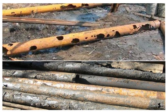
Figure 3.
External steel casing corrosion from acidic water attack [32].
In certain chemical conditions, specifically, the combined presence of archaebacteria, CaSO4·2H2O, and a slow source of CH4 in a stratum, acidic conditions (H2S generated) are created and external steel corrosion accelerated by both the +ΔT and the increasing acidity. We note that the methane may even be traveling up the geothermal production well outside the casing [33].
2.2. Reservoir Condition
Mineral dissolution and precipitation, ΔT and ΔP, and steel goods corrosion are the main issues related to chemical disequilibrium in deep geothermal systems [34]. Geothermal fluids have diverse chemical components due to the diversity of geological settings (e.g., silica-rich, carbonate-rich, chloride brines, etc.). The recharging water source and associated dissolved gases also define the chemical characteristics of the geothermal fluid, and these may change with time because of the perturbation caused by production and injection. The precipitation of minerals or induced corrosion/scaling leads to small particles carried in suspension into the porous reservoir, altering the system’s porosity and permeability. Bächler and Kohl [35] investigated such changes in a deep geothermal system using coupled Thermal-Hydraulic-Chemical (THC) modeling. The study found that the system’s efficiency decreased more rapidly with more mineral dissolution at the start of the project, and it slowed down over a longer time. These results were attributed to the disequilibrium of the system at the start, then changes in the equilibrium condition over time [35]. For production and service life calculations, flow pathway impairment from particles and precipitates is an important disequilibrium effect.
Microbially induced (mediated) corrosion, MIC [36], and fouling affect geothermal energy projects (as well as other industrial activities); designing and implementing protection requires multiple knowledge perspectives—material science and metallurgy, electrochemistry, biochemistry, and microbiology [37]. Salas et al. [38] showed MIC’s impact on the deterioration of geothermal power plant structures (e.g., vapor ducts and cooling tower supports), noting bacterial activity at temperatures as high as 140 °C. A MIC problem in the primary surface loop may migrate to the subsurface as corrosion products, and temperature changes impact the reservoir’s chemical conditions and change the system’s flow properties [39]. Tubular goods may experience general (e.g., steel thinning) or localized corrosion (e.g., pitting) [40]. Uniform corrosion [41], pitting, crevice, and contact (galvanic) corrosion [42,43,44], microbially mediated corrosion [45], and oxygen corrosion [38] are all common in geothermal systems.
Thermohydrochemical reservoir processes are impacted by stimulation efforts (e.g., hydraulic fracturing with gels, acid injection, etc.), and injection/production leads to ΔT and ΔP, triggering mineral precipitation. Even reservoir rock and fluid heat conductivities can be altered by ΔT and ΔP. Blöcher et al. [46] showed that significant changes occur in the porosity and permeability of a sandstone reservoir when the effective stress (σ) is increased, as shown in Figure 4.

Figure 4.
Decrease in measured porosity and permeability of Flechtinger Sandstone geothermal reservoir because of increased effective stress (here called effective pressure) [46].
Remedial/preventive methods include cleaning, jetting, and waste removal in well workovers, and soft acidizing during stimulation to remove carbonate precipitates, with remediation processes guided by leak-off and injection step-rate testing and data from other chemical and physical monitoring methods [47,48,49]. Note that soft acidizing of geothermal systems is taken to mean injecting the same acid volume as used in conventional oil and gas acid treatments but at a much lower rate [48,50]. Salimzadeh and Nick [51] developed a two-way chemical coupling method to include mineral dissolution in Thermal-Hydraulic-Mechanical (THM) coupling, generating a coupled Thermal-Hydraulic-Mechanical-Chemical (THMC) approach to explain noticeable changes in reservoir properties arising from chemical disequilibrium.
3. Geomechanical Conditions
Fluid injection into a geothermal well system can induce stress changes at a scale through hydromechanical, poroelastic, and thermoelastic mechanisms. In this section, we evaluated the geomechanics responses for cold water injection into a geothermal double-well system. Following geophysics symbology, we use “S” to mean total stress, which at a point is the sum of the effective stress σ and the pore fluid pressure, viz.: Sv = σv + Pp; SHmax = σHmax + Pp; Shmin = σhmin + Pp. Injecting cold water into hot rock perturbs the stress in two ways: through ΔP and temperature ΔT. As a preliminary example, assuming a uniform planar and linearly elastic stratum, the effective horizontal stress change (Δσh − MPa) for a uniform reservoir wide temperature change (ΔTr − K) is
where the elastic properties defining the volume change (ΔV) are Young’s modulus (E − GPa), Poisson’s ratio (ν), and the coefficient of thermal expansion (αT − K−1); for a stiff rock E ≈ 60 GPa, αT ≈ 10−5 K−1, and ν ≈ 0.2, so that a ΔT of −30 K can lead to a large effective stress change, Δσh ≈ −22 MPa in this example. In cases with steep temperature gradients from cooling (across boundaries of large permeability contrast, for example), stress changes can readily induce shear slip of pre-existing fractures or small faults and exceptionally trigger the shear yield or tensile rupture of intact rock. This is also impacted by pressure changes, and to evaluate shear yield, it is necessary to introduce a shear slip criterion.
The potential for fracture slip or shear yield of intact rock from combined ΔT and ΔP effects from the fluid injection can be evaluated using simplified (i.e., linearized) Mohr-Coulomb (MC) yield criteria [52]
where, τ is the shear stress at yield (shear slip) along a plane, usually, a rock weakness plane in naturally fractured rock masses, and σn is the normal effective stress acting across the slip plane. C and φ are the cohesion and internal friction angle, respectively; that is, the shear strength parameters of the slip surface (e.g., fault or fracture surface). To apply the MC criterion, the in-situ effective stress tensor, the slip plane shear strength, and the slip plane orientation are needed. Determining the effective stress tensor (σij) at the region of potential slip is a coupled THM problem.
Fluid injection changes stress through hydromechanical (ΔP − Δσ), poroelastic (ΔP − ΔS), and thermoelastic (ΔT − Δσ) volume changes that generate three-dimensional strains (εij) and therefore stress changes (ΔSij and Δσij). Of course, Δσij, in turn, leads to more ΔV; hence, the term “coupled” is used: no process is independent of the others. The first mechanism accounts for the bulk compressibility effect ΔV, the second for the porous rock ΔV, and the third for the thermally induced ΔV. Quantification of ΔV requires coupling heat conduction and convection with fluid flow and stress-strain analysis. In general, in the low permeability host rock, higher pressures reduce the frictional strength (Equation (3)) of a slip plane by decreasing the effective normal stress (), facilitating yield. In a Mohr stress diagram (Figure 5a) using total stresses, a pressure increase shifts the yield envelope (black line) into the Mohr circle (the stress state), and yield is said to have occurred when stresses lie outside the criterion limit.
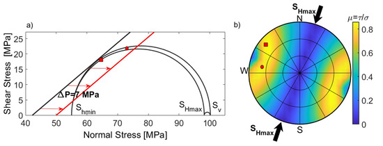
Figure 5.
(a) 3D Mohr circles showing stress condition and slip tendency due to fluid injection in the deep geothermal reservoir Groß Schönebeck in the North German Basin. The red line is the Coulomb failure criterion when pore pressure has been elevated by 7 MPa, and (b) The lower hemisphere stereonet plot illustrates the slip-tendency (ratio of resolved shear to normal stress) and stress direction.
Because stiff, brittle earth materials store elastic strain energy but are strain-weakening, a sudden stress drop (weakening) accompanies shear slip, and a very small fraction of the released strain energy is evidenced as strain waves (seismic waves). Although the fluid-injection fracture-slip-induced deformation is not high, generally far less than a centimeter, Δσij may also trigger and reactivate nearby faults that are near critical stress conditions, causing felt seismicity and casing shear problems [53]. Injection-induced earthquakes are usually small with moment magnitude < 0. However, there are cases where large magnitude (>1) injection-induced seismicity has been recorded [54]. Two groups of field parameters can impact the magnitude and rate of injection-induced seismicity: controllable operational parameters that include fluid injection pressure, rate, temperature, and volume [54]. Uncontrollable subsurface parameters include the initial state of stress and pore pressure, size and density of pre-existing faults/fractures, fault/fracture orientation and shear strength, and other geomechanics parameters [55].
Figure 5 shows the effect of the pressure increase on the fault reactivation in the deep doublet geothermal Groß Schönebeck project in the North German Basin, where fluid-injection-induced seismicity is recorded [56]. The stress state at the injection depth of 4035 m is a normal faulting regime with Sv = 100 MPa, SHmax = 98 MPa, Shmin = 55 MPa, and Pp = 43 MPa [56]. Faults striking in the SHmax direction with dip angles of 45–75° are critically stressed; increasing pore pressure by less than 7 MPa increases the risk of induced seismicity on two fault sets: the NW-SE set (rectangle), and the E-W set (Mohr circle). Shear slip of natural fractures in strong rocks is usually a dilatant process, so the rock mass permeability is enhanced in certain directions, which in turn will alter the fluid flow patterns, and probably increase the permeability anisotropy in a rock mass.
The second mechanism, poroelasticity, governs fluid pressure change effects on in-situ states of stress and rock mass deformation [52,57]. Geothermal SedHeat wells are drilled into porous, permeable reservoirs, and ΔP causes volume changes that lead to stress changes, altering porosity and permeability. Engelder and Fisher [58] demonstrated that stress/pore pressure changes in a normal faulting regime as follows
where α is Biot’s poroelastic coefficient, for this relationship, it is assumed that vertical stress remains constant.
In this study, we evaluated the pore pressure stress coupling at different tectonic stress settings employing 3D geomechanics modeling. According to Anderson’s classification scheme [52], the three states of stress are normal (Sv > SHmax > Shmin), strike-slip (SHmax > Sv > Shmin), and reverse faulting regimes (SHmax > Shmin > Sv), where S values are the principal compressive stresses. One-way hydromechanical coupling is performed to evaluate the fluid injection effects on the stress tensor using the finite element platform Visage™ Geomechanics Simulator. We considered a hypothetical reservoir located at a depth of 2250 m where Pp is hydrostatic (≈11 MPa/km), and Sv increases at a rate of ≈26 MPa/km. Simulation boundaries were sufficiently distant to have no effects on the deformations in the affected (reservoir) zone. This model was subjected to a +ΔP of 8 MPa.
Figure 6 shows the results for (a) normal faulting, (b) strike-slip, and (c) reverse faulting stress regimes, respectively. Pre- and post-injection stress tensors at the point of fluid injection are illustrated by 3D Mohr circles. In all cases, injecting fluid shifts the Mohr circles (stress magnitudes) leftward toward the yield criterion, indicating that the stress state is closer to the yield criterion. Note that in the case of the normal fault, incipient slip is apparent for the values chosen (Pp = 35 MPa). In the normal faulting regime, the effective maximum and minimum principal stress difference (σv − σhmin) decreases as Pp is increased, but not for the other two regimes; notably, in different states of stress, the local stress tensor components respond differently to fluid injection.

Figure 6.
Mohr’s Circle in three dimensions showing the effect of fluid injection (for pressure difference, ΔP = 8 MPa) at different states of stress: (a) normal faulting, (b) strike-slip, and (c) reverse faulting stress regimes.
The third ΔV mechanism, thermoelasticity, leads to slow rock shrinkage with cold water injection [52], inducing stress changes. The thermally induced stress magnitude (ΔσT) effect was illustrated above (Equation (2)). We re-iterate that the stress redistribution process is driven by volume changes governed by ΔT and the host rock elastic properties [59]: ΔV = V·ΔT·αT, where the bulk rock thermal-expansion coefficient is αT. As shown above, in stiff rocks (high E), ΔσT effects can be very large. Cooling occurs mostly convectively in permeable rocks, but in bounding low-permeability rocks, only conduction obtains. Therefore, strong local time-dependent differences in thermal expansion can take place, leading to shear stress concentrations at bounding interfaces (usually bedding), leading to shearing and induced seismicity. Figure 7 demonstrates how cool fluid injection changes the local state of stress around the cooled zone. Thermally-induced contraction decreases σij in the cooled zone, and redistributes stresses around to maintain mechanical stress equilibrium. A similar (poroelastic) effect is expected to take place with ΔP, but the two processes, ΔT and ΔP, have widely different characteristic time scales. This implies that the rock deformation and stress changes are likely to be dominated by ΔP in the early time of a geothermal project, whereas ΔT effects become increasingly more important during the late time [60].

Figure 7.
Induced thermal stress resulting from cold fluid injection into a geothermal reservoir. The color scale is the relative temperature range from 60 to 100 °C.
Hence, the zone being cooled relative to the rock mass loses compressive stress from thermoelastic shrinkage; this lost stress is transferred as increased stress to the surrounding, uncooled rock to maintain stress equilibrium (Figure 7). This stress redistribution generally increases local shear stresses, but the zone of maximum shear stress increase is distant from the injection well, near the region of the thermal front, which can be quite sharp because the reservoir rock shrinks quickly (convectively), whereas the overburden shrinks very slowly (conductively).
In geothermal well systems, increasing the flow rate of the geothermal fluid can lead to the generation of a local turbulent flow regime, particularly around the injection well due to pumping the fluid flow with high pressure, affecting efficiency. In the short-term, the high flow rate of the injection fluid can lead to an increase in thermal energy production, although it has the inverse effect in the long-term. In addition, the turbulent flow near the injection well can cause more stress and, consequently, damage the well because of the induced stress created over time.
4. Heat-and Flow-Transport Challenges
4.1. System Thermal Issues
Eventually, loss of capacity to produce sufficient fluid rates at high enough temperatures to sustain commercial operation defines a geothermal reservoir’s life-time [46]. The reservoir characteristics of porosity, permeability, initial temperature, and bulk heat capacity are performance indicators of a geothermal injection/production well system. These indicators dictate daily energy production and reservoir life-time. The recovery factor is the amount of producible energy compared to the total available energy, and it depends on the use of the heat at the surface (electrical power, power + heat, seasonal heat storage, etc.). Pure power production leads to a lower energy recovery factor. However, if the geothermal system is cooling, useful heat can likely be produced long after the period of electricity generation. Capital cost, operational cost, and the geothermal system performance over time define commercial viability [47]. The performance of a geothermal well system (commercially viable life-time and energy recovery) is related to both the natural physical parameters listed above and human-controlled factors. Transitioning a decaying geothermal system from power generation to sensible heat use makes great economic sense because the capital investment payback is dominated by the early years, when electricity is being generated. For long-term sustainability, this means there must be additional SedHeat systems added on episodically as the initial systems decay because of the slow drop of heat energy provision.
Human controlled parameters are [48]: (1) discharge rate from the reservoir, (2) injection rate and fluid input temperature, and (3) well spacing. Production, injection, and well spacing effects have been studied by Kazemi et al. [8] to show their importance on the life-time of a doublet geothermal system. Porosity, permeability, chemical components of pore fluid, initial temperature, reservoir minerals, and their chemical components and mechanical parameters, reservoir thickness, and the presence of shale layers and their thicknesses are the main natural subsurface physical parameters [48,49]. Thermal depletion happens by continuing injection of cooler water until the production well shows thermal breakthrough and decline in temperature, impacting the efficiency of the doublet geothermal system. Various means of extending life-span and project utility might include episodic electrical power production through integration of other energy sources (wind, solar, diesel, etc.), developing such a large well spacing that life-span is increased (but recovery efficiency may drop), and by thermal recharging from industrial waste heat sources or by use of excess solar and wind energy when available. Solar thermal collectors can be installed instead of photovoltaic systems, and these can feed the hot fluids into the system before the heat exchanger or afterward [61,62], depending on the time of year, the electrical power demand, and other factors. In all cases, the thermal capacity retention time of a project depends significantly on human-controlled parameters, given a set of physical system parameters [50].
Production-recovery cycles comprise an important process in any geothermal well system and need to be considered in any life-time assessment and economical assessment of such a system. A case study on a Riehen reservoir exploited by a doublet geothermal system showed that the recovery of the reservoir is closely related to the cyclic production-recovery plan [50], suggesting that shorter cycles allowed more thermal energy to be produced. If there is some component of natural fluids recharge (a leaky reservoir), beneficially encouraging such recharge involved not only rate management but pressure management. Thermal breakthrough will occur sooner if production continues without letting the reservoir regain some heat through conduction from the surrounding rocks. The exploitation of the doublet aquifer is also affected by the pressure gradient in the aquifer, changing heat retention in the reservoir [63]. Table 1 summarizes some parameters for more effective heat production from a doublet geothermal system.

Table 1.
Effective parameters for heat production from a doublet geothermal system.
The main thermodynamic/commercial objective of a geothermal system must be economically viable heat recovery efficiency, defined as the ultimate recovered heat over the reserved heat in the aquifer [64,65,66,67,68], subject to commercial criteria. In order to achieve optimum efficiency from a geothermal system, the main goal should be to optimize heat recovery from the reservoir to service both the electrical grid needs and to provide useful heat for habitat and industrial needs. Most geothermal power plants are designed to provide electrical energy/heat to the surrounding area, which often is a local detached grid [69,70,71,72]. If geothermal electrical power can be used in a large grid to provide special services such as peak shaving or load displacement, the value of the energy provision increases.
4.2. Reservoir Geological Aspects
A first-order factor in the productivity of a geothermal SedHeat well array is the stratigraphy and flow properties of the reservoir. Figure 8 is a representation of a doublet in a typical SedHeat situation.

Figure 8.
Geological disposition factors in doublet efficacy.
The target stratum is bounded by impermeable strata: U shale is the upper advective flow boundary, L shale is the lower advective flow boundary. Given typical permeability contrasts in geological media, it is usually assumed that the SedHeat fluid reservoir is bounded by impermeable strata, such that advective flow is confined to the more permeable intervals. In litharenite, SedHeat reservoirs (sand-silt-shale), the productive interval contains granular beds (sandstones) of differing permeability; the most common distribution is to find higher values in the lower beds, grading upward to lower permeability in the uppermost beds (also characteristic of transgressive sedimentary regimes).
Commonly, there are intraformational low-permeability strata, deposited under more quiescent flow conditions, called silts or shales; they are of much lower permeability than the low k sandstone, usually by more than two orders of magnitude. Furthermore, because of processes in the original depositional environment, these low-permeability strata may be continuous at the doublet spacing scale (shale C), or they may be laterally discontinuous (shale A and shale B). The complete disposition of the various strata between the doublet pair is difficult to specify, even with excellent seismic investigation; usually, stratigraphic details are known only from the geophysical logs available from the production and injection wells.
One may assume that in the stratigraphic disposition shown, the permeability of the lowermost sandstone is several times that of the central sandstone, which in turn is several times that of the upper sandstone (a permeability range for the sandstones might be from 1 D to 0.1 D). The silty shale interbeds (labeled “shale”) have permeability values less than 0.001 D, so they may be considered functionally impermeable in the context of advective fluid flux. Thus, heat in these strata (water and mineral phases) can migrate to the sandstone only by conductive heat transport, and is thence taken to the production well advectively (blue arrows). Similarly, the heat in the bounding strata (U-, L-shale) can only flow conductively and be exploited when the advectively flowing fluid in the sandstone drops below the original temperature.
Another issue in a natural, unbounded reservoir is that flow is not constrained by lateral no-flow boundaries. Assuming an original pressure Po and similar pressure build-up and draw-down cones around each well (blue line), part of the injected fluid will dissipate into the farfield to the right, driven by the positive ΔP, and at the production well, part of the warm fluids will come from the farfield to the left, driven by the pressure sink -ΔP. The heterogeneity that is characteristic of all sedimentary rock geothermal reservoirs invariably decreases the energy recovery and the energy recovery rate. The most optimistic recovery scenario is the isotropic, constant permeability case, with the further assumption that the local permeability is not impaired by geochemical processes or fine-grained solids migration into the reservoir.
Finally, we point out that in geothermal reservoirs that are dominated by flow in natural fractures, there is an important short-circuiting mechanism associated with thermal effects: maximum fracture aperture increase occurs in the fracture with the most flow, reinforcing the flow rate [73]. It remains unclear if this process can be somewhat suppressed by flow management and by thermal recharge [74]. Assessing the commercial viability of a geothermal SedHeat reservoir that involves the injection of cold water is and will remain a challenging task. Currently, SedHeat projects in laterally extensive reservoirs that do not require re-injection of cold water seem commercially viable because the fluid entry temperature remains constant from continuous recharge. Injection/production projects based on well-doublets or variants require more careful evaluation.
5. Conclusions
Geothermal energy appears to be a green, generally available, potentially constant, and stable source of energy. If economically viable, it is a practical and sustainable solution for supplying energy needs (power or thermal) and can decrease environmental challenges and threats (e.g., air pollution, global warming, climate change). Geothermal well systems can be used to generate both electrical and thermal energy. Despite the advantages listed here, these systems will evidence challenges over time, including heat conductivity, chemical, and mechanical issues, which will affect their operational efficiency, as well as costs. Based on the literature and studies conducted, the following results can be concluded:
- -
- Chemical reactions can lead to flow-path alterations, as well as varying the heat exchange rate between rock and water, resulting in variations in the reservoir’s porosity-permeability and heat capacity.
- -
- Corrosion and scaling damage in the well systems decrease their operational efficiency and impact their life-span.
- -
- Mineral dissolution and precipitation under ΔT and ΔP conditions play a substantial role in chemical disequilibrium in geothermal systems, particularly in deep ones.
- -
- Factors having a significant impact on the life-span and heat recovery of a geothermal well system include energy discharge rate and strategy, injection rate, temperature and heat management, and well spacing.
- -
- Optimization of heat recovery from the reservoir while sustaining a profitable commercial outcome is the most important issue in geothermal well systems.
- -
- Fluid injection into a geothermal well system can induce stress changes at a scale that will increase the likelihood of fault/fracture reactivation and induced seismicity. Understanding the magnitude of these events and their recurrence in time is important.
- -
- Channeling, short-circuiting, leaking, heterogeneity, and permeability impairment can all negatively affect project viability and must be carefully assessed during site assessment.
Knowing the issues discussed in this article will help designers/engineers to better design and implement geothermal SedHeat systems, based on the local geological characteristics of the resources and geographical and climate conditions, resulting in improving operations and enhancing efficiency of the systems as well as reducing their associated costs and risks.
Author Contributions
All authors contributed to the writing and editing of the paper. All authors have read and agreed to the published version of the manuscript.
Funding
This study received no external funding.
Acknowledgments
The authors would like to thank Schlumberger for making the Petrel E&P Platform available for this study.
Conflicts of Interest
The authors declare no conflict of interest.
Nomenclature
| cp | Heat capacity, J/kg·K |
| C | Cohesion of the rock, Pa |
| E | Young’s modulus, Pa |
| Ė | Energy rate or power, J/s |
| P | Pressure, Pa |
| Pp | Pore pressure, Pa |
| ΔP | Pressure difference, Pa |
| Q | Heat production capacity, J/K |
| Flow rate (of fluid), kg/s | |
| Sv | Vertical stress, Pa |
| SHmax | Maximum horizontal stress, Pa |
| Shmin | Minimum horizontal stress, Pa |
| ΔT | Temperature difference, K |
| To | Initial reservoir temperature, K |
| Tin | Fluid temperature entering the energy extraction system, K |
| Tout | Fluid temperature exiting the energy extraction system, K |
| V | Volume, m3 |
| α | Biot’s poroelastic coefficient, - |
| αT | Rock thermal-expansion coefficient, K−1 |
| υ | Poisson’s ratio, - |
| σ | Effective stress, Pa |
| σn | Effective normal stress, Pa |
| φ | Friction angle of the slip plane or intact rock, ° |
| τ | Shear stress, Pa |
Abbreviations
| EG | Enhanced (Engineered) Geothermal |
| GHG | Greenhouse Gas |
| HDR | Hot Dry Rock |
| MC | Mohr-Coulomb |
| MIC | Microbiologically Induced Corrosion |
| THC | Thermal-Hydraulic-Chemical |
| THM | Thermal-Hydraulic-Mechanical |
| THMC | Thermal-Hydraulic-Mechanical-Chemical |
References
- Bahadori, M.N.; Dehghani-Sanij, A.R. Wind Towers: Architecture, Climate and Sustainability; Sayigh, A., Ed.; Springer: Basel, Switzerland, 2014. [Google Scholar]
- Dehghani-Sanij, A.R. Cisterns: Sustainable Development, Architecture and Energy; Sayigh, A., Ed.; River Publishers: Aalborg, Denmark, 2016. [Google Scholar]
- Dehghani-Sanij, A.R.; Tharumalingam, E.; Dusseault, M.B.; Fraser, R. Study of energy storage systems and environmental challenges of batteries. Renew. Sustain. Energy Rev. 2019, 104, 192–208. [Google Scholar] [CrossRef]
- Looney, B. Energy Outlook, 2020th ed.; BP p.l.c.: London, UK, 2020; p. 157. [Google Scholar]
- Dusseault, M.B.; Mahbaz, S.B.; Fraser, R.A.; Dehghani-Sanij, A.R. Hybrid Energy Systems: Delivering Reliable Heat and Power in Remote Locations. In Proceedings of the 46th Annual Yellowknife Geoscience Forum Abstracts; Northwest Territories Geological Survey: Yellowknife, NT, Canada, 2018. [Google Scholar]
- Kinney, C.; Dehghani-Sanij, A.R.; Mahbaz, S.B.; Dusseault, M.B.; Nathwani, J.S.; Fraser, R.A. Geothermal energy for sustainable food production in Canada’s remote northern communities. Energies 2019, 12, 4058. [Google Scholar] [CrossRef]
- Mahbaz, S.B.; Dehghani-Sanij, A.R.; Dusseault, M.B.; Nathwani, J.S. Enhanced and integrated geothermal systems for sustainable development of Canada’s northern communities. Sustain. Energy Technol. Assess. 2020, 37, 100565. [Google Scholar] [CrossRef]
- Kazemi, A.R.; Mahbaz, S.B.; Dehghani-Sanij, A.R.; Dusseault, M.B.; Fraser, R. Performance evaluation of an enhanced geothermal system (EGS) in the Western Canada Sedimentary Basin. Renew. Sustain. Energy Rev. 2019, 113, 109278. [Google Scholar] [CrossRef]
- Dehghani-Sanij, A.R.; Bahadori, M.N. Ice-Houses: Energy, Architecture, and Sustainability; Elsevier, Imprint by Academic Press: Amsterdam, The Netherlands, 2021. [Google Scholar]
- Soltani, M.; Kashkooli, F.M.; Dehghani-Sanij, A.R.; Kazemi, A.R.; Bordbar, N.; Farshchi, M.J.; Elmi, M.; Gharali, K.; Dusseault, M.B. A comprehensive study of geothermal heating and cooling systems. Sustain. Cities Soc. 2019, 44, 793–818. [Google Scholar] [CrossRef]
- Soltani, M.; Kashkooli, F.M.; Dehghani-Sanij, A.R.; Nokhosteen, A.; Ahmadi-Joughi, A.; Gharali, K.; Mahbaz, S.B.; Dusseault, M.B. A comprehensive review of geothermal energy evolution and development. Int. J. Green Energy 2019, 16, 971–1009. [Google Scholar]
- Guney, M.S.; Tepe, Y. Classification and assessment of energy storage systems. Renew. Sustain. Energy Rev. 2017, 75, 1187–1197. [Google Scholar] [CrossRef]
- Dehghani-Sanij, A.R.; Mahbaz, S.B.; Dusseault, M.B. Feasibility study of enhanced geothermal Energy secondary application for agricultural production in Canadian Northern territories. In Proceedings of the 46th Annual Yellowknife Geoscience Forum Abstracts; Northwest Territories Geological Survey: Yellowknife, NT, Canada, 2018. [Google Scholar]
- Bilgili, M.; Ozbek, A.; Sahin, B.; Kahraman, A. An overview of renewable electric power capacity and progress in new technologies in the world. Renew. Sustain. Energy Rev. 2015, 49, 323–334. [Google Scholar]
- Rybach, L. Geothermal Sustainability. In Proceedings of the European Geothermal Congress, Unterhaching, Germany, 30 May–1 June 2007. [Google Scholar]
- Grasby, S.E.; Allen, D.M.; Bell, S.; Chen, Z.; Ferguson, G.; Jessop, A.; Kelman, M.; Ko, M.; Majorowicz, J.; Moore, M.; et al. Geothermal Energy Resource Potential of Canada; Geological Survey of Canada: Ottawa, ON, Canada, 2011; p. 322.
- Pérez, R.E. Shallow geothermal energy: Geological energy for the ecological transition and its inclusion in European and national energy policies. Eur. Geol. Eur. Geol. 2019, 47, 28–32. [Google Scholar]
- Lee, K.C. Classification of geothermal resources by exergy. Geothermics 2001, 30, 431–442. [Google Scholar]
- Axelsson, G. Production capacity of geothermal systems. In Proceedings of the Workshop for Decision Makers on the Direct Heating Use of Geothermal Resources in Asia, Tianjin, China, 11–18 May 2008. [Google Scholar]
- Schiavone, R.; De Natale, G.; Borgia, A.; Troise, C.; Moretti, R.; Somma, R. Seismogenic potential of withdrawal-reinjection cycles: Numerical modelling and implication on induced seismicity. Geothermics 2020, 85, 101770. [Google Scholar] [CrossRef]
- Holbrook, J.; Moore, J.N.; Elsworth, D.; Block, K.A.; Allis, R.; Einstein, H. An Opportunity of Geothermal Proportions in Sedimentary Basins. Sediment. Rec. 2014, 12, 4–9. [Google Scholar] [CrossRef]
- Green, S.; McLennan, J.; Panja, P.; Kitz, K.; Allis, R.; Moore, J. Geothermal battery energy storage. Renew. Energy 2017, 164, 777–790. [Google Scholar] [CrossRef]
- Carlino, S.; Somma, R.; Troiano, A.; Di Giuseppe, M.G.; Troise, C.; De Natale, G. The geothermal system of Ischia Island (southern Italy): Critical review and sustainability analysis of geothermal resource for electricity generation. Renew. Energy 2014, 62, 177–196. [Google Scholar] [CrossRef]
- Carlino, S.; Troiano, A.; Di Giuseppe, M.G.; Tramelli, A.; Troise, C.; Somma, R.; De Natale, G. Exploitation of geothermal energy in active volcanic areas: A numerical modelling applied to high temperature Mofete geothermal field, at Campi Flegrei caldera (Southern Italy). Renew. Energy 2016, 87, 54–66. [Google Scholar] [CrossRef]
- Satman, A. Sustainability of Geothermal Doublets. In Proceedings of the 36th Workshop on Geothermal Reservoir Engineering, SGP-TR-191, Stanford, CA, USA, 31 January–2 February 2011. [Google Scholar]
- Esteves, A.F.; Santos, F.M.; Pires, J.C.M. Carbon dioxide as geothermal working fluid: An overview. Renew. Sustain. Energy Rev. 2019, 114, 109331. [Google Scholar] [CrossRef]
- Banks, D. Thermogeological assessment of open loop well doublet schemes: An analytical approach. In Proceedings of the 27th Annual Groundwater Conference; International Association of Hydrogeologists (Irish Group): Tullamore, Ireland, 2007. [Google Scholar]
- Banks, D. Hydrogeological assessment of open-loop well-doublet schemes: A review and synthesis of analytical approaches. Hydrogeol. J. 2009, 17, 1149–1155. [Google Scholar] [CrossRef]
- Ungemach, P.; Antics, M.; Papachristou, M. Sustainable Geothermal Reservoir Management. In Proceedings of the World Geothermal Congress, Antalya, Turkey, 24–29 April 2005. [Google Scholar]
- Ungemach, P. Chemical Treatment of Low Temperature Geofluids. In Proceedings of the International Course on District Heating Schemes, Cesme, Izmir, Turkey, 19–25 October 1997. [Google Scholar]
- Lerm, S.; Westphal, A.; Miethling-Graff, R.; Alawi, M.; Seibt, A.; Wolfgramm, M.; Würdemann, H. Thermal effects on microbial composition and microbiologically induced corrosion and mineral precipitation affecting operation of a geothermal plant in a deep saline aquifer. Extremophiles 2013, 17, 311–327. [Google Scholar] [CrossRef]
- Courtesy Terry, R. Carter from a published AAPG, American Association of Petroleum Geologists. In Proceedings of the GeoConvention 2014, Calgary, AB, Canada, 12–16 May 2014. [Google Scholar]
- Dusseault, M.B.; Jackson, R.E. Seepage pathway assessment for natural gas to shallow groundwater during well stimulation, in production, and after abandonment. Environ. Geosci. 2014, 21, 107–126. [Google Scholar] [CrossRef]
- Alt-Epping, P.; Diamond, L.W.; Häring, M.O.; Ladner, F.; Meier, D.B. Prediction of water–rock interaction and porosity evolution in a granitoid-hosted enhanced geothermal system, using constraints from the 5 km Basel-1 well. Appl. Geochem. 2013, 38, 121–133. [Google Scholar] [CrossRef]
- Bächler, D.; Kohl, T. Coupled thermal–hydraulic–chemical modelling of enhanced geothermal systems. Geophys. J. Int. 2005, 161, 533–548. [Google Scholar] [CrossRef]
- Gerchakov, S.M.; Little, B.J.; Wagner, P. Probing Microbiologically Induced Corrosion. Corrosion 1986, 42, 689–692. [Google Scholar] [CrossRef]
- Liu, H.; Cheng, Y.F. Microbial corrosion of initial perforation on abandoned pipelines in wet soil containing sulfate-reducing bacteria. Colloids Surf. B Biointerfaces 2020, 190, 110899. [Google Scholar] [CrossRef] [PubMed]
- Salas, V.B.; Wiener, S.M.; de la Peña, L.R.; Bedolla, N.M. Deterioration of materials in geothermal fields in Mexico. Mater. Corros. 2000, 51, 698–704. [Google Scholar] [CrossRef]
- Iberl, P.; Alt, N.S.A.; Schluecker, E. Evaluation of corrosion of materials for application in geothermal systems in Central Europe. Mater. Corros. 2015, 66, 733–755. [Google Scholar] [CrossRef]
- Letcher, T.; Sayigh, A. (Eds.) Comprehensive Renewable Energy; Elsevier: Oxford, UK, 2012. [Google Scholar]
- DIN EN ISO. 15156-153 Grundbegriffe und Definitionen; Beuth Verlag GmbH: Berlin, Germany, 1999. [Google Scholar]
- Weißbach, W. Werkstoffkunde; Vieweg þ Teubner Verlag: Wiesbaden, Germany, 2012. [Google Scholar]
- Gülich, J.F. Kreiselpumpen; Springer: Berlin/Heidelberg, Germany, 2010. [Google Scholar]
- Merkblatt 821. Edelstahl Rostfrei–Eigenschaften; Informationsstelle Edelstahl Rostfrei: Düsseldorf, Germany, 2012. [Google Scholar]
- Dinh, H.T.; Kuever, J.; Muszmann, M.; Hassel, A.W.; Stratmann, M.; Widdel, F. Iron corrosion by novel anaerobic microorganisms. Nature 2004, 427, 829–832. [Google Scholar] [CrossRef] [PubMed]
- Blöcher, M.G.; Zimmermann, G.; Moeck, I.; Brandt, W.; Hassanzadegan, A.; Magri, F. 3D numerical modeling of hydrothermal processes during the lifetime of a deep geothermal reservoir. Geofluids 2010, 10, 406–421. [Google Scholar] [CrossRef]
- Ungemach, P. Insight into Geothermal Reservoir Management. In Textbook; Rosca, M., Ed.; European Summer School on Geothermal Energy Applications: Oradea, Romania, 2001; pp. 43–76. [Google Scholar]
- Ventre, A.V.; Ungemach, P. Soft Acidizing of Damaged Geothermal Injection Wells–Discussion of Results Achieved in the Paris Basin. In Proceedings of the 23rd Workshop on Geothermal Reservoir Engineering, Stanford, CA, USA, 26–28 January 1998; pp. 33–43. [Google Scholar]
- Ungemach, P.; Ventre, A.V.; Nicolaon, S. Tracer Leak Off Tests as Means of Checking Well Integrity, Application to Paris Basin Geothermal Production Wells. In Proceedings of the 27th Workshop on Geothermal Reservoir Engineering, SGP-TR-71, Stanford, CA, USA, 28–30 January 2002. [Google Scholar]
- Portier, S.; Vuataz, F.D.; Nami, P.; Sanjuan, B.; Gérard, A. Chemical stimulation techniques for geothermal wells: Experiments on the three-well EGS system at Soultz-sous-Forêts, France. Geothermics 2009, 38, 349–359. [Google Scholar] [CrossRef]
- Salimzadeh, S.; Nick, H.M. A coupled model for reactive flow through deformable fractures in enhanced geothermal systems. Geothermics 2019, 81, 88–100. [Google Scholar] [CrossRef]
- Jaeger, J.C.; Cook, N.G.; Zimmerman, R. Fundamentals of Rock Mechanics; John Wiley & Sons, Inc.: Hoboken, NJ, USA, 2009. [Google Scholar]
- Dusseault, M.B.; Bruno, M.S.; Barrera, J. Casing shear: Causes, cases, cures. Soc. Pet. Eng. Drill. Completion J. 2001, 16, 98–107. [Google Scholar] [CrossRef]
- McGarr, A. Maximum magnitude earthquakes induced by fluid injection. J. Geophys. Res. Solid Earth 2014, 119, 1008–1019. [Google Scholar] [CrossRef]
- Yaghoubi, A.; Dusseault, M.B.; Mahbaz, S.B.; Leonenko, Y. Probabilistic Injection-Induced Fault Slip Assessment in Fox Creek Alberta. In Proceedings of the 54th US Rock Mechanics/Geomechanics Symposium, ARMA-2020-1880, Golden, CO, USA, 28 June–1 July 2020. [Google Scholar]
- Blöcher, G.; Cacace, M.; Jacquey, A.B.; Zang, A.; Heidbach, O.; Hofmann, H.; Kluge, C.; Zimmermann, G. Evaluating micro-seismic events triggered by reservoir operations at the geothermal site of Groß Schönebeck (Germany) Rock Mech. Rock Eng. 2018, 51, 3265–3279. [Google Scholar] [CrossRef]
- Hojka, K.; Dusseault, B.M.; Bogobowicz, A.D. Analytical solutions for transient thermoelastic stress fields around a borehole during fluid injection into permeable media. J. Can. Pet. Technol. 1993, 32. [Google Scholar] [CrossRef]
- Engelder, T.; Fischer, M. Influence of poroelastic behavior on the magnitude of minimum horizontal stress, Sh in overpressure parts of sedimentary basins. Geology 1994, 22, 949–952. [Google Scholar]
- Stephens, G.; Voight, B. Hydraulic fracturing theory for conditions of thermal stress. Int. J. Rock Mech. Min. Sci. Geomech. Abstr. 1982, 19, 279–284. [Google Scholar] [CrossRef]
- Jalali, M.R.; Evans, K.F.; Valley, B.C.; Dusseault, M.B. Relative importance of THM effects during non-isothermal fluid injection in fractured media. In Proceedings of the 49th US Rock Mechanics/Geomechanics Symposium, San Francisco, CA, USA, 28 June–1 July 2015. [Google Scholar]
- Greenhut, A.D. Modeling and Analysis of Hybrid Geothermal-Solar Thermal Energy Conversion Systems. Ph.D. Thesis, Massachusetts Institute of Technology, Cambridge, MA, USA, 2009. [Google Scholar]
- Erdogan, A.; Colpan, C.O.; Cakici, D.M. Thermal design and analysis of a shell and tube heat exchanger integrating a geothermal based organic Rankine cycle and parabolic trough solar collectors. Renew. Energy 2017, 109, 372–391. [Google Scholar] [CrossRef]
- Willems, C.J.L.; Nick, H.M.; Weltje, G.J.; Bruhn, D.F. An evaluation of interferences in heat production from low enthalpy geothermal doublets systems. Energy 2017, 135, 500–512. [Google Scholar] [CrossRef]
- Babaei, M. Integrated carbon sequestration–geothermal heat recovery: Performance comparison between open and close systems. Transp. Porous Media 2019, 126, 249–273. [Google Scholar] [CrossRef]
- Vik, H.S.; Salimzadeh, S.; Nick, H.M. Heat recovery from multiple-fracture enhanced geothermal systems: The effect of thermoelastic fracture interactions 500 m. Renew. Energy 2018, 121, 606–622. [Google Scholar]
- Crooijmans, R.A.; Willems, C.J.L.; Nick, H.M.; Bruhn, D.F. The influence of facies heterogeneity on the doublet performance in low-enthalpy geothermal sedimentary reservoirs. Geothermics 2016, 64, 209–219. [Google Scholar] [CrossRef]
- Williams, C.F. Updated methods for estimating Recovery Factors for geothermal resources. In Proceedings of the 32nd Workshop on Geothermal Reservoir Engineering, Stanford, CA, USA, 22–24 January 2007. [Google Scholar]
- Salimzadeh, S.; Grandahl, M.; Medetbekova, M.; Nick, H.M. A novel radial jet drilling stimulation technique for enhancing heat recovery from fractured geothermal reservoirs. Renew. Energy 2019, 139, 395–409. [Google Scholar] [CrossRef]
- Vasilyeva, M.; Babaei, M.; Chung, E.T.; Spiridonov, D. Multiscale modeling of heat and mass transfer in fractured media for enhanced geothermal systems applications. Appl. Math. Model. 2019, 67, 159–178. [Google Scholar] [CrossRef]
- Lopez, S.; Hamm, V.; Le Brun, M.; Schaper, L.; Boissier, F.; Cotiche, C.; Giuglaris, E. 40 years of Dogger aquifer management in Ile-de-France, Paris Basin, France. Geothermics 2010, 39, 339–356. [Google Scholar] [CrossRef]
- Nador, A.; Kujbus, A.; Toth, A.N. Geothermal energy use, country update for Hungary. In Proceedings of the European Geothermal Congress, Strasbourg, France, 19–24 September 2016. [Google Scholar]
- Szanyi, J.; Kovács, B. Utilization of geothermal systems in South-East Hungary. Geothermics 2010, 39, 357–364. [Google Scholar] [CrossRef]
- Gee, B.; Gracie, R. Comparison of fully-coupled and sequential solution methodologies for enhanced geothermal system. Comput. Methods Appl. Mech. Eng. 2021, 670, 113554. [Google Scholar] [CrossRef]
- Iorio, M.; Carotenuto, A.; Corniello, A.; Di Fraia, S.; Massarotti, N.; Mauro, A.; Somma, R.; Vanoli, L. Low Enthalpy Geothermal Systems in Structural Controlled Areas: A Sustainability Analysis of Geothermal Resource for Heating Plant (The Mondragone Case in Southern Appennines, Italy). Energies 2020, 13, 1237. [Google Scholar] [CrossRef]


Publisher’s Note: MDPI stays neutral with regard to jurisdictional claims in published maps and institutional affiliations. |
© 2021 by the authors. Licensee MDPI, Basel, Switzerland. This article is an open access article distributed under the terms and conditions of the Creative Commons Attribution (CC BY) license (http://creativecommons.org/licenses/by/4.0/).