Article

A Novel Vascular Intervention Surgical Robot Based on Force Feedback and Flexible Clamping

1
Parallel Robot and Mechatronic System Laboratory of Hebei Province, Yanshan University, Qinhuangdao 066004, China
2
Key Laboratory of Advanced Forging & Stamping Technology and Science of Ministry of Education, Yanshan University, Qinhuangdao 066004, China
3
Academy for Engineering & Technology, Fudan University, Shanghai 200433, China
*
Author to whom correspondence should be addressed.
Appl. Sci. 2021, 11(2), 611; https://doi.org/10.3390/app11020611
Submission received: 10 December 2020 / Revised: 31 December 2020 / Accepted: 7 January 2021 / Published: 10 January 2021

Abstract

:
At present, most vascular intervention surgical robots (VISRs) cannot achieve effective force feedback and lack regulation of the clamping force of the guidewire. In this paper, a VISR based on force feedback and clamping force regulation is proposed. It is a master–slave system consisting of a master manipulator that is flexible enough and a slave wire feeder that can deliver the guidewire. Accurate force feedback is established to ensure the safety of the operation, and the clamping force of the guidewire can be regulated in real time. Based on the dynamic analysis of the mechanism, the control scheme of the system is designed. The two-dimensional fuzzy PID (Proportion Integration Differentiation) controller is equipped with on-line tuning parameters and anti-interference capabilities. The sine and step signals are selected to carry out simulation analysis on the controller. The performance of the designed VISR was verified by a force feedback experiment, a clamping force regulation experiment and a vascular model experiment.

1. Introduction

Vascular interventional surgery means that under the guidance of medical imaging, the doctor manipulates the catheter or guidewire into the human blood vessel through a small wound and then moves to the lesion for treatment, so as to embolize the malformed blood vessel, dissolve the thrombus, dilate the narrow blood vessel and so on [1,2,3]. However, doctors who have been exposed to radiation for a long time cannot completely eliminate radiation hazards, even if they wear radiation-proof lead clothing [4,5], and heavy protective clothing will also bring doctors cervical or lumbar pain [6]. In addition, due to the bending and narrowing of human blood vessels and their many branches, the doctor is required to not shake too much during the operation. As such, the doctor should be highly focused during the operation, which can easily cause fatigue in the doctor, thus leaving him or her unable to guarantee the success and accuracy of the operation [7]. The application of robot technology to the field of vascular interventional technology can largely relieve the burden of doctors and free them from the high radiation environment [8]. With the help of robot technology, surgical safety and accuracy can be improved, and the accidents caused by human fatigue factors can be reduced [9,10].
In recent years, several commercial vascular intervention surgical robot (VISR) systems have been developed. For example, the Sensei robot system developed by Hansen Medical has been successfully used in clinical applications in different fields for remote operations using operable catheters and jackets [11,12]. The Amigo robot system, designed by Catheter Robotics, has three degrees of freedom and can carry out such actions as the propulsion of the active catheter, twisting the catheter and bending the catheter head [13,14]. The Niobe robot system developed by Stereotaxis Incorporation manages the position and incorporation of the catheter by using magnetic navigation technology [15,16]. All three are active catheter systems, but issues such as the size and safety of active catheters limit their use in cardiovascular surgery, compared with the wide range of passive catheters. Currently, the most mature passive catheter system is the Corpath GRX robot system [17,18,19] developed by Corindus Vascular Robotics, which includes a wire feeder and a remote operating station for the operation of catheters, guidewires, balloons and other instruments. In addition, some research institutions have also conducted research in this field, such as Hanyang University, the University of Western Ontario, the Beijing Institute of Technology and Shanghai University [20,21,22,23].
In remote interventional surgery, in addition to the guidance of medical images, doctors also need to use the assistance of robots to judge whether the front end of the guidewire touches the blood vessel [24]. Therefore, the establishment of force feedback has become an important factor affecting the success rate of a surgery, which includes two aspects: the accurate detection of proximal force at the slave end and the formation of force sensation at the master end. However, most of the VISR system only tests the proximal force without providing the operator with a force sensation [25,26]. Otherwise, some agencies use commercial master manipulators, such as the Geomagic Touch X system developed by 3D Systems, which is not flexible enough for vascular intervention surgery and is not in accordance with traditional surgical operations [27].
During an operation, doctors use their fingers to propel and twist the catheter or guidewire, which can sense the degree of clamping and adjust the clamping force in real time. When the VISR is used for surgery, there are two methods for clamping the catheter or guidewire: rolling transmission with a friction wheel [28] and reciprocating propulsion with a sliding platform [29]. Neither of these two methods are able to perform flexible clamping on the catheter or guidewire; that is, the doctor cannot sense the clamping force in real time and adjust it. Moreover, the former is difficult to reliably clamp due to its slippage between the friction wheel and the catheter or guidewire, while the latter will damage the surface of the catheter or guidewire if the clamping force is too large [30]. Therefore, flexible clamping of the catheter or guidewire is critical, but few researchers have conducted research based on flexible clamping.
In light of these problems, a novel vascular intervention surgical robot (VISR) based on force feedback and flexible clamping was designed. In Section 2, the system is described in detail, and the mechanisms of force feedback and flexible clamping are introduced. In Section 3, the dynamics of the system are analyzed. In Section 4, the two-dimensional fuzzy PID controller is designed according to the dynamic model, and its function is analyzed. Four types of experiments to evaluate the performance of the proposed VISR are introduced in Section 5, and the results obtained are discussed. Finally, our conclusions are given in Section 6.

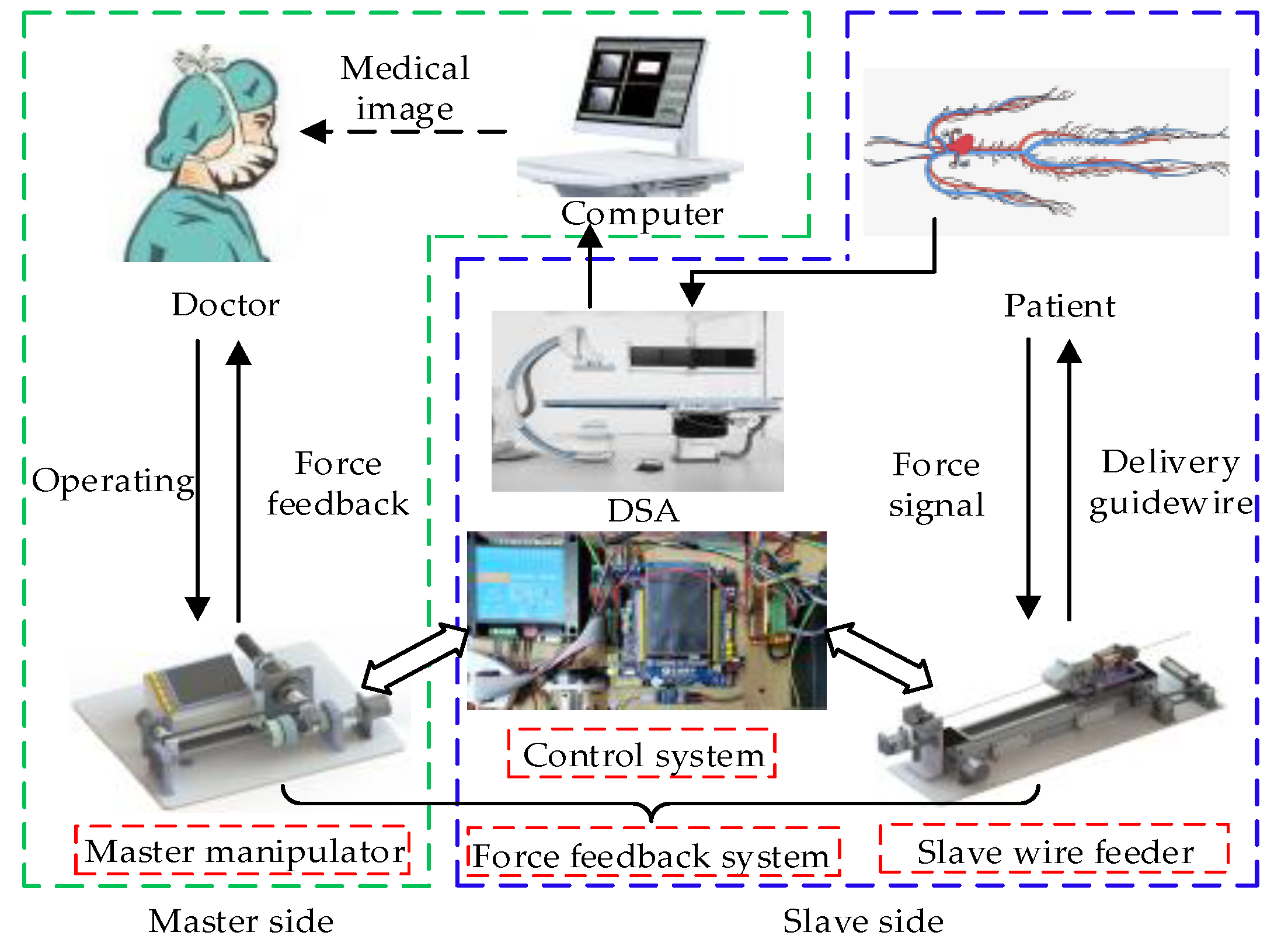
2. System Description

The designed VISR is a master–slave system, including the master manipulator, the slave wire feeder, the control system and the force feedback system between them. The workflow and information interaction of different components in the VISR are shown in Figure 1. The doctor operates the master manipulator in a safe isolation room. The control system then receives this operating signal and issues control instructions to the slave wire feeder. Then, the slave wire feeder copies the doctor’s operation in the operating room to flexibly clamp and deliver the catheter or guidewire, so as to retain the doctor’s dexterity on the premise of ensuring the doctor’s safety. In this process, the slave wire feeder measures the proximal force of the guidewire in real time, and the master manipulator forms a force sensation according to this, thus ensuring the safety of the surgery.

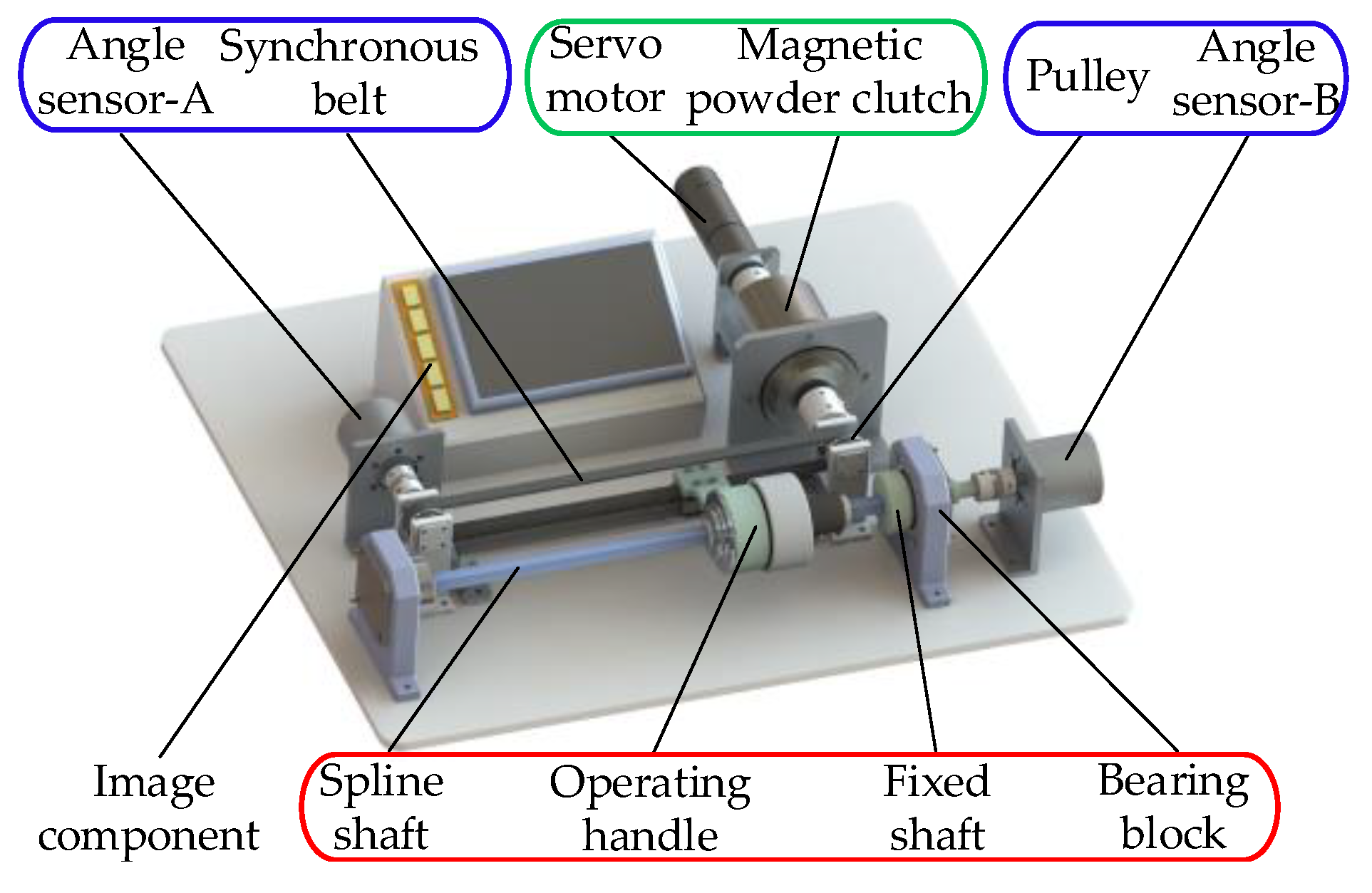
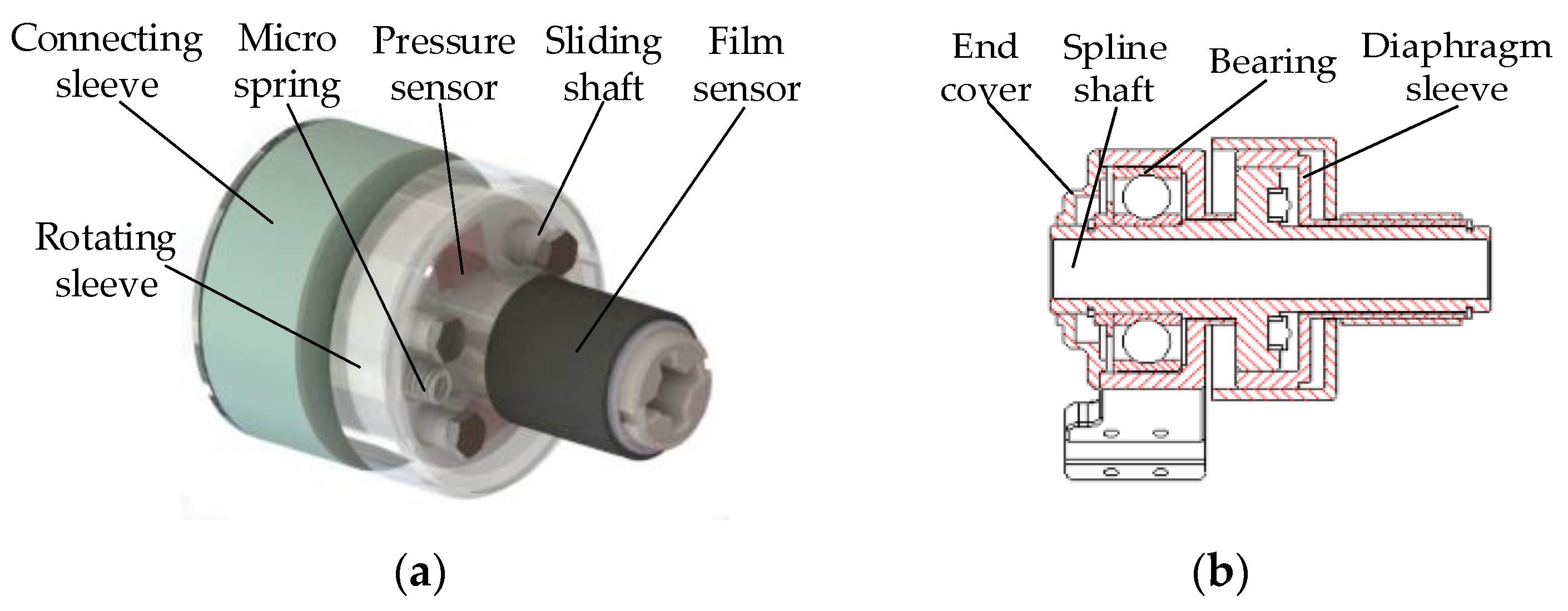
2.1. Master Manipulator

The master manipulator includes an operating component, a position detection component, a force sensation component and an image component, as shown in Figure 2. The operating component is composed of a spline shaft, operating handle, fixed shaft and bearing block. The damped operating handle slides on the spline shaft. The fixed shaft is attached to both sides of the spline shaft to limit its axial movement. The position detection component consists of angle sensor-A, angle sensor-B (P2500, Miran Technology, Shenzhen, CN), a synchronous belt and a pulley. The operating handle is fixed with the synchronous belt, and the propulsion information is converted into rotation angle information through the synchronous belt group and then collected through angle sensor-A, connected to the left end of the synchronous belt group. Angle sensor-B is connected with the extended end of the fixed shaft through a coupling to collect the rotation information. The resolution of the angle sensor is 0.355°, the independent linearity is ±0.1%, and the repeatability is 0.01°. The force sensation component is composed of a servo motor (RE10, Maxon Motor, Canton of Upper Walden, Switzerland) and a magnetic powder clutch (CD-HSY-5, Lanling, Haian, CN). The right end of the synchronous belt group is connected with the output end of the magnetic powder clutch, and the input end of the magnetic powder clutch is connected with the servo motor through the coupling. Image components are used to display intraoperative force–position information and assist doctors to judge the state of the guidewire tip.
The operating handle decouples the propulsion and rotation of the guidewire, as shown in Figure 3. The connecting sleeve is fixed to the synchronous belt. The rotating sleeve drives the spline shaft to rotate, and the two can rotate relative to each other. Therefore, the circumferential rotation of the spline shaft does not affect the axial propulsion of the operating handle. When the doctor delivers the guidewire, the middle finger and thumb squeeze the film sensor (Flexiforce-1lbsA201, Tekscan, Boston, US) to produce a signal to clamp the guidewire, while the forward thrust of the finger acts on the pressure sensor (MDL: SBT674-1 kg, Simbatouch, Guangzhou, CN) to produce a signal to propel the guidewire. The diaphragm sleeve and the rotating sleeve can slide relative to each other through the sliding shaft. In the case of no external force, a certain pressure threshold can be maintained through the micro spring and the adjusting bolt.

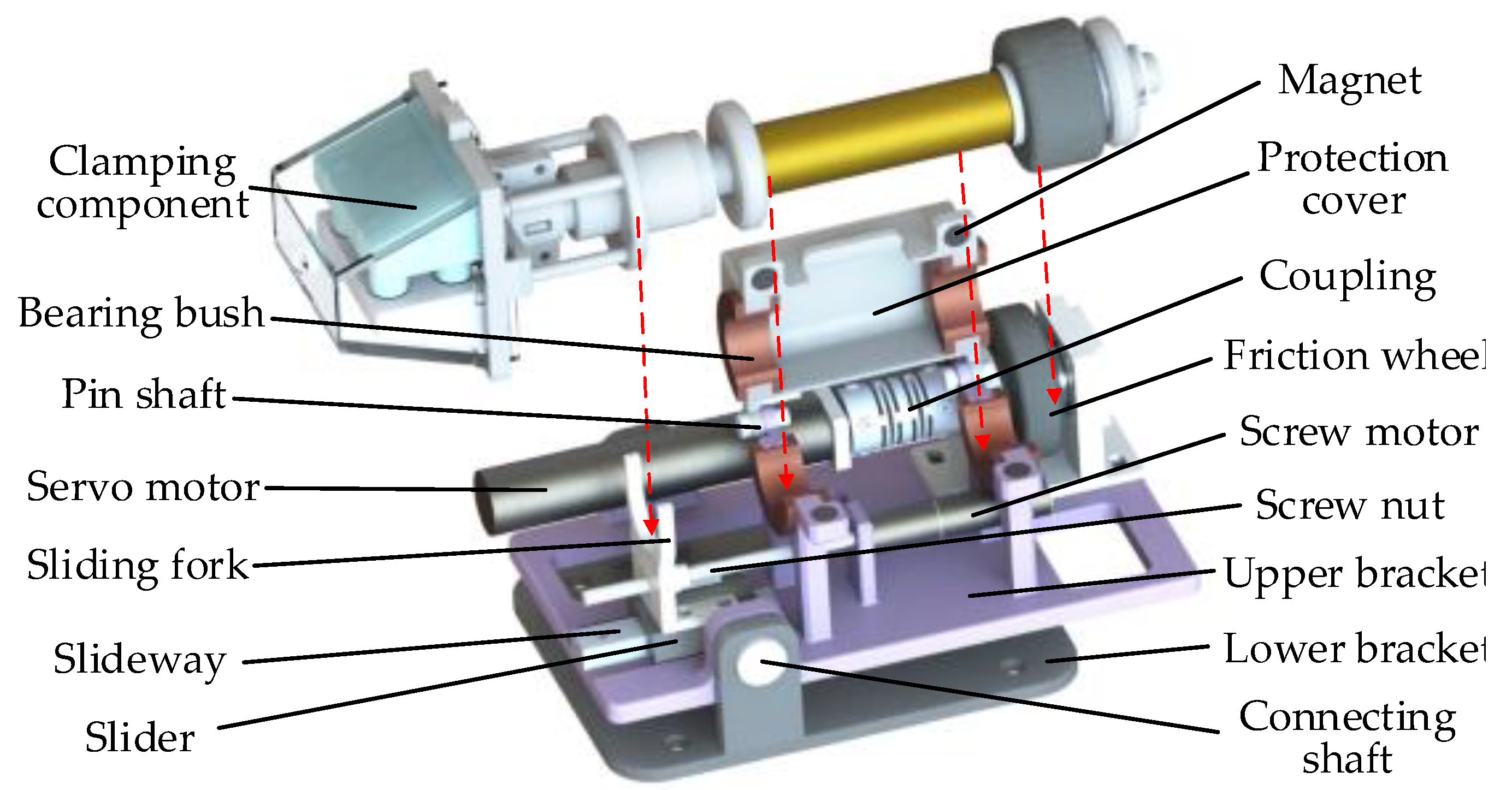
2.2. Slave Wire Feeder

The length of the guidewire is generally 1800~1950 mm, while the slave wire feeder has a stroke of −200 mm. Therefore, the guidewire needs to be continuously propelled through the coordination between fixed and moving components, as shown in Figure 4. The Y-type valve holder is located at the front of the slave wire feeder to hold the medical Y-type valve and adjust its angle. Fixed components include cams driven by a servo motor (RE10, Maxon Motor, Canton of Upper Walden, Switzerland) and clamping blocks, which are turned on when the guidewire is propelled forward and closed when the moving component is returned. The moving component is used to drive the clamping component to move on the sliding module. The clamping component can be used for the flexible clamping of guidewires of different types, and the clamping force can be adjusted or measured in real time. The driving component is connected to the right shaft of the sliding module, which is composed of a servo motor (28SYK43, UPTECH Robotics, CN), a synchronous belt group, a fixed component and a frame to realize the propulsion or return of the moving component. The encoder (Modbus RTU, 8 bits/circle, RealwayTech, Beijing, CN) is connected to the shaft at the left end of the sliding module for recording the position of the guidewire. The axial propulsion error of the system is less than 0.2 mm.
The moving component is shown in Figure 5. The lower bracket is fixed on the sliding module and drives the whole module to move in an axial direction. The clamping component is used for the clamping guidewire. It is placed on the bearing bush of the upper bracket, and the whole component can be removed for convenient disinfection. A servo motor (RE8, Maxon Motor, Canton of Upper Walden, Switzerland) used for twisting is installed on the upper bracket. It is connected with the friction wheel through the coupling. The protection cover is used to ensure the friction wheel group is in close contact, so as to realize the rotational motion of the clamping component. The screw motor (DCX10L, Maxon Motor, Canton of Upper Walden, Switzerland) used for clamping is installed under the clamping component. The screw nut is connected with the sliding fork. Driven by the screw motor, the sliding fork can reciprocate and move on the slider, then propel the sliding sleeve of the clamping component to achieve flexible clamping of the guidewire.
The internal structure of the clamping component is shown in Figure 6. A fixed sleeve and a copper bush are installed on the hollow shaft, and the end is mounted with a driven friction wheel. The sliding sleeve can slide on the hollow shaft and propel the clamping blocks to move on the wedge clamping sleeve through the push rod to realize the clamping of the guidewire. Due the action of the spring, the clamping component is in a normally open state. Only when the screw motor propels the sliding fork will the guidewire be clamped, and the clamping force will be adjusted in real time. The clamping sensor (MDL: SBT674-1 kg, Simbatouch, Guangzhou, CN) is embedded in the lower clamping block to measure the clamping force during operation and display it on the image component of the master manipulator.

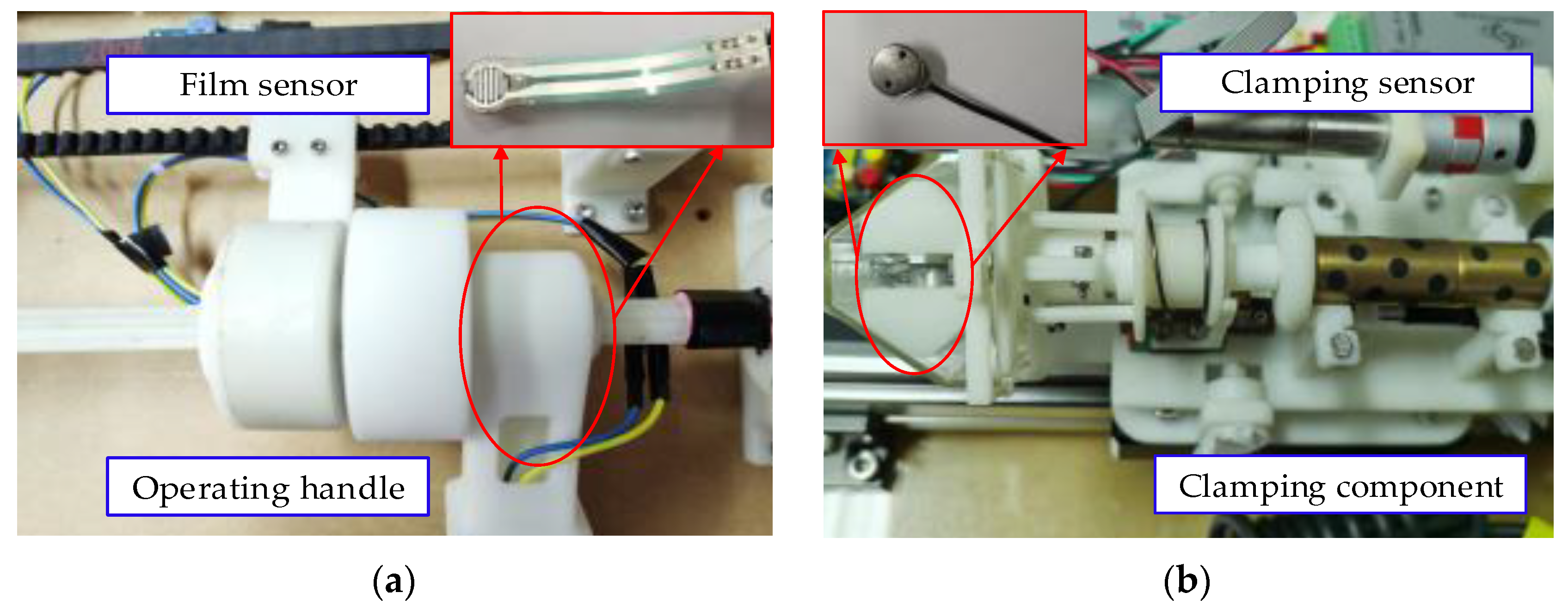
2.3. Force Feedback System

In order to realize the force feedback and the flexible clamping, for the master manipulator, the servo motor and magnetic powder clutch combination scheme is adopted to provide the required force sensation. The relative pressure between the operating handle and the hand is maintained by adjusting the speed of the servo motor. According to the slip characteristic of the magnetic powder clutch, when the input excitation current remains unchanged, the transferred torque is not affected by the rotational speed difference between the main and the driven parts. Therefore, when the magnetic powder clutch provides a force sensation, it can weaken the shaking phenomenon caused by braking torque. A film sensor and a pressure sensor are set in the operating handle to detect the clamping force and the propulsion force exerted by the doctor, respectively, as shown in Figure 7.
For the slave wire feeder, the actual clamping force of the guidewire is collected through the clamping sensor. When the guidewire tip touches the blood vessel and is subjected to force, the resistance detection mechanism will amplify the force through the lever principle and convert it into positive pressure against the resistance sensor (MDL: SBT674-5 kg, Simbatouch, Guangzhou, CN). The spring is set between the upper and lower bracket to balance the effect of gravity on the mechanism itself. The lever arm can be changed by adjusting the position of the resistance sensor to regulate the amplification ratio, which can be set to two here, as shown in Figure 8.

3. Dynamic Analysis

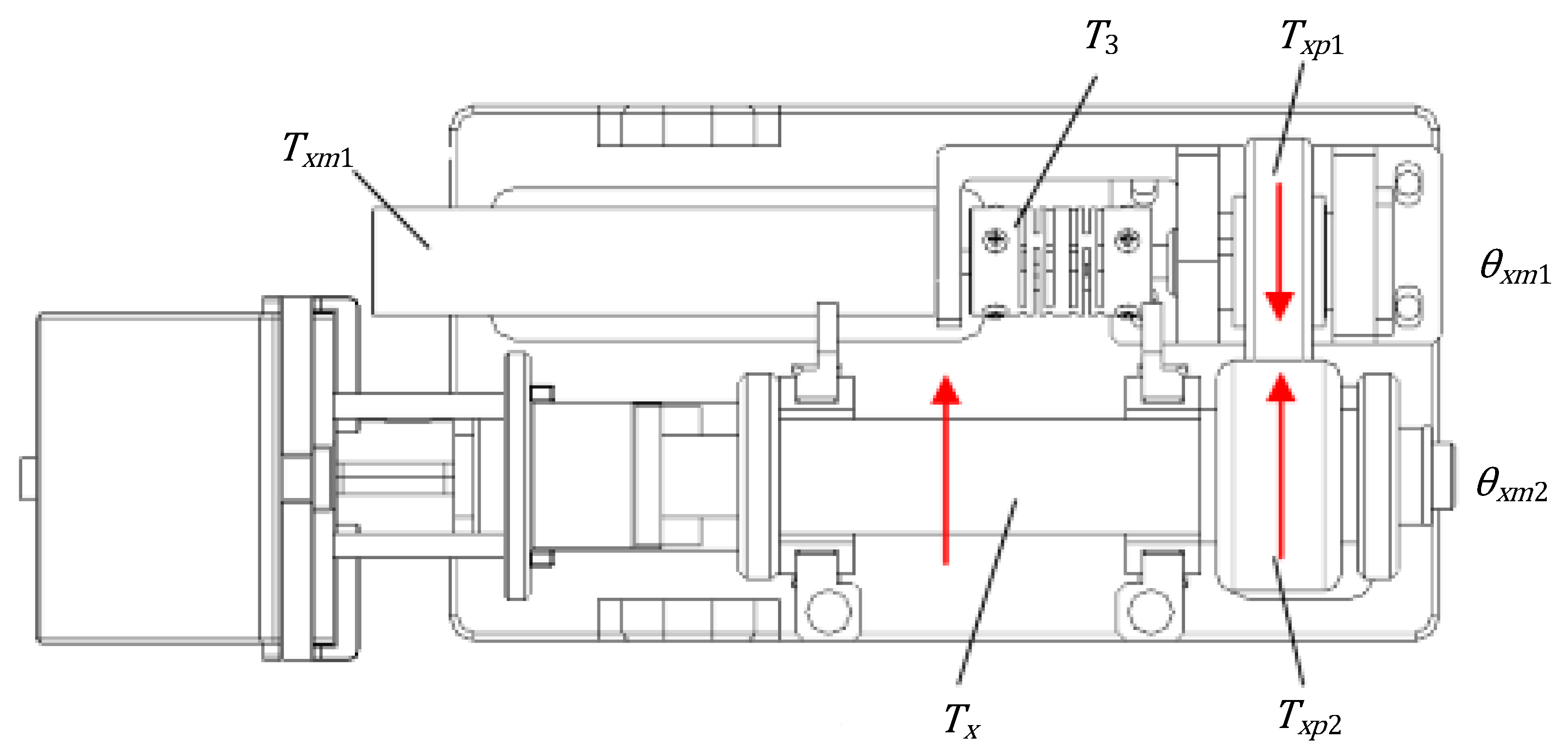
3.1. Dynamical Model of Propulsion

For the motion diagram of the propulsion of the guidewire, as shown in Figure 9, its transmission principle is as follows. The servo motor, as the power source of the slave wire feeder, drives the synchronous belt group through elastic coupling-1. The synchronous belt group converts the driving torque of the servo motor into the driving force of the moving load, and the moving load fixed on the synchronous belt realizes the propulsion of the guidewire with the positive and negative rotation of the motor.
According to the transmission process of the propulsive motion of the slave wire feeder, the dynamic equation of the components in the transmission mechanism is established in turn, ignoring the influence of the friction between components and nonlinear factors such as deformation in the motion process. The dynamic equation of the output side of the servo motor is
T m = J s d 2 θ m d t 2 + B s d θ m d t + T 1
where T m is the driving torque of the propulsion motor, J s is the inertia of the propulsion motor and its reducer, θ m is the angle of the propulsion motor output shaft, B s is the damping coefficient of the propulsion motor and T 1 is the driving torque of elastic coupling-1.
The dynamic equation from coupling-1 to the moving load is
T 1 = J 1 d 2 θ m d t 2 + J p 1 d 2 θ m d t 2 + J p 2 d 2 θ m d t 2 + J 2 d 2 θ m d t 2 + J p 3 d 2 θ m d t 2 + J p 4 d 2 θ m d t 2 + F L · d 2
where J 1 is the inertia of elastic coupling-1, J 2 is the inertia of elastic coupling-2, J p is the inertia of the pulley, F L is the moving load and d is the diameter of the pulley.
The moving load fixed on the synchronous belt group is analyzed as follows:
F L = m t d 2 x s d t 2 + μ v d x s d t + μ c m t g
where m t is the mass of the slider and the object mounted on it, μ v and μ c are the sticky coefficient of friction and Cullen coefficient of friction, respectively, and x s is the axial displacement of the guidewire.
The relationship between the axial displacement of the guidewire and the angle of the servo motor output shaft is as follows:
x S = θ m · d 2
The above formula, joined with prior equations and values, yields
T m = 2 d ( J s + J 1 + J 2 + J p 1 + J p 2 + J p 3 + J p 4 + m t d 2 4 ) d 2 x s d t 2 + ( B s 2 d + μ v d 2 ) d x s d t + μ c m t g · d 2
For simplified modeling, μ c m t g · d 2 is labeled as a disturbance.

3.2. Dynamical Model of Rotation

The principle of the rotation of the guidewire is similar to the propulsion, and its motion diagram is shown in Figure 10. The servo motor, as the power source for rotating, is fixed with elastic coupling-3 and drives the clamping component to rotate through the friction wheel group.
According to the transmission process of the rotating motion of the slave wire feeder, the dynamics equations of the relevant components are established in turn, ignoring the influence of nonlinear factors such as deformation and vibration of the friction wheel group during the motion process. The dynamic equation of the output side of the servo motor is
T x m 1 = J x s d 2 θ x m 1 d t 2 + B x s d θ x m 1 d t + T 3
where T x m 1 is the driving torque of the rotation motor, J x s is the inertia of the rotation motor and its reducer, θ x m 1 is the angle of the rotation motor output shaft, B x s is the damping coefficient of the rotation motor and T 3 is the driving torque of elastic coupling-3.
The dynamic equation from elastic coupling-3 to the clamping component is as follows:
T 3 = J 3 d 2 θ x m 1 d t 2 + J x p 1 d 2 θ x m 1 d t 2 + J x p 2 d 2 θ x m 2 d t 2 + T x
where J 3 is the inertia of elastic coupling-3, J x p is the inertia of the friction wheel, θ x m 2 is the angle of the clamping component and T x is the torque of the clamping component.
The torque of the clamping component is analyzed as follows:
T x = J x d 2 θ x m 2 d t 2 + F f · d x 2
where J x is the inertia of the clamping component, F f is the load on the clamping component and d x is the diameter of the clamping component.
The relationship between the rotation angle of the clamping component and the rotation angle of the output shaft of the servo motor is as follows:
θ x m 2 = θ x m 1 · i
The above formula, joined with prior equations and values, yields
T x m 1 = 1 i ( J x s + J 3 + J x p 1 ) d 2 θ x m 2 d t 2 + ( J x p 2 + J x ) d 2 θ x m 2 d t 2 + B x s i · d θ x m 2 d t + μ x v m x t g · d x 2
For simplified modeling, μ x v m x t g · d x 2 is labeled as a disturbance.

4. Design of the Control System

Due to the infinite freedom of the guidewire and the nonlinear uncertain disturbance caused by the flexible components in the mechanism, an accurate dynamical model cannot be established. In addition, the friction force of the mechanism itself and intraoperative shaking of the doctor’s hand will also cause nonlinear interference to the system. These disturbances not only affect the tracking accuracy of the master–slave position, but also have great influence on the acquisition of force signals. Therefore, the control system of the VISR must be able to eliminate the above effects to a certain extent, while the simple closed-loop control system and conventional PID controller cannot meet these requirements. In this paper, the fuzzy control strategy is added to the PID controller to make it have on-line tuning parameters and anti-interference functions.

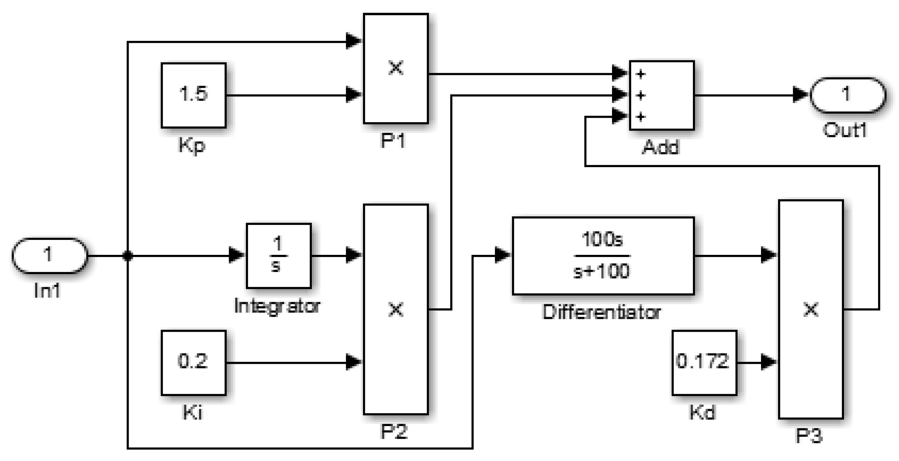
4.1. Design of the Traditional Controller and the PID Controller

The above model is static, but considering that the interaction of various factors in the actual wire feeding process is dynamic, according to the fuzzy PID control theory, the conventional PID control system of the mechanism should be set up, and then the initial values of Δ k p , Δ k i and Δ k d in the system can be obtained. In Section 3.1, the dynamic equation of the propulsion was obtained, which was substituted into the data and a Laplace transform was performed. Then, the second-order transfer function of the system was obtained as follows:
G ( s ) = 1 0.01186 s 2 + 0.09602 s  
The traditional controller and PID controller were built in the Simulink environment of the MATLAB software (2016a, MathWorks, Natick, MA, US), as shown in Figure 11 and Figure 12. The traditional controller was a simple closed-loop control system, in which negative feedback was added to the transfer function of the system. On this basis, the PID module in the Simulink library was called upon and added to the aforementioned system to obtain the PID controller. The PID parameters were adjusted by the empirical trial and error method to achieve stability of the system, and the final parameters were determined as K p = 1.5 , K i = 0.2 and K d = 0.172 .

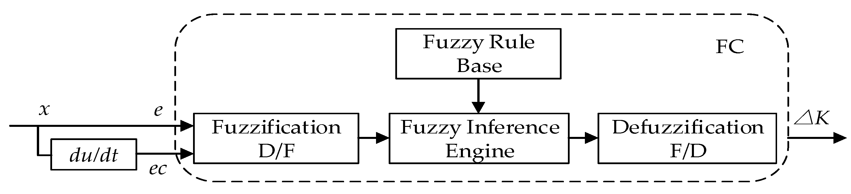
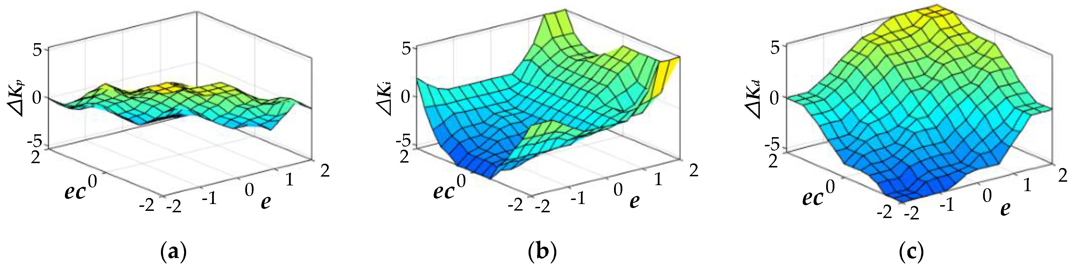
4.2. Design of the Two-Dimensional Fuzzy PID Controller

The input value of the fuzzy controller designed in this paper included the deviation ( e ) and deviation change rate ( e c = d u / d t ). Since they were two components of x , the controller was regarded as a two-dimensional fuzzy PID controller, and its principle is shown in Figure 13.
The fuzzy controller can be expressed as a mapping from the input to the output:
Δ K = F C ( e , e c )
where F C is the fuzzy controller, and the input ( e , e c ) and the outputs Δ k p , Δ k i and Δ k d , by selecting the appropriate membership functions μ ( x ) , transform for a fuzzy subset of the fuzzy theory domain. Its basic theoretical domain is U = [ 1 , 1 ] , the fuzzy theoretical domain is N = [ 0.1 , 0.1 ] and the quantization factor is k = 10 . Since the basic domain of x is continuous, its membership function μ ( x ) is triangular (Equation (13)), and the transition adjustment of boundary is Gaussian (Equation (14)):
μ ( x ) = { 0 x a x a b a a x b c x c b b x c 0 x c
μ ( x ) = e ( x c F ) 2 / ω
The fuzzy subsets A 1 and A 2 of the input quantities were determined as {Minus Big, Minus Medium, Minus Small, Zero, Plus Small, Plus Medium, Plus Big}, and the corresponding symbols were { N B , N M , N S , Z O , P S , P M , P B } . The fuzzy subset B 1 , B 2 and B 3 of the output quantities were determined as {Minus Big, Minus Medium, Minus Small, Zero, Plus Small, Plus Medium, Plus Big}, and the corresponding symbols were { N B , N M , N S , Z O , P S , P M , P B } . The design of the fuzzy rules, based on expert experience method, is
R ( l ) :   IF   e   is   A 1 i   and   e c   is   A 2 j ,   THEN   Δ K p   is   B 1 l   Δ K i   is   B 2 l   Δ K d   is   B 3 l
The resulting fuzzy control surface of the outputs Δ k p , Δ k i and Δ k d is shown in Figure 14.
The fuzzy controller outputs a fuzzy set. According to the formula k = u / n , the fuzzy domain is transformed into the basic domain. The area barycenter method is used to de-fuzzy the parameters:
z 0 = df ( z ) = a b z μ ( z ) d z a b μ ( z ) d z
where z 0 is the exact value, z is the fuzzy value, μ ( z ) is the membership function and [ a , b ] is the theoretical domain.
Hence, the scale factor for de-fuzzification can be obtained: Δ k p = 0.5 , Δ k i = 20 and Δ k d = 0.2 .

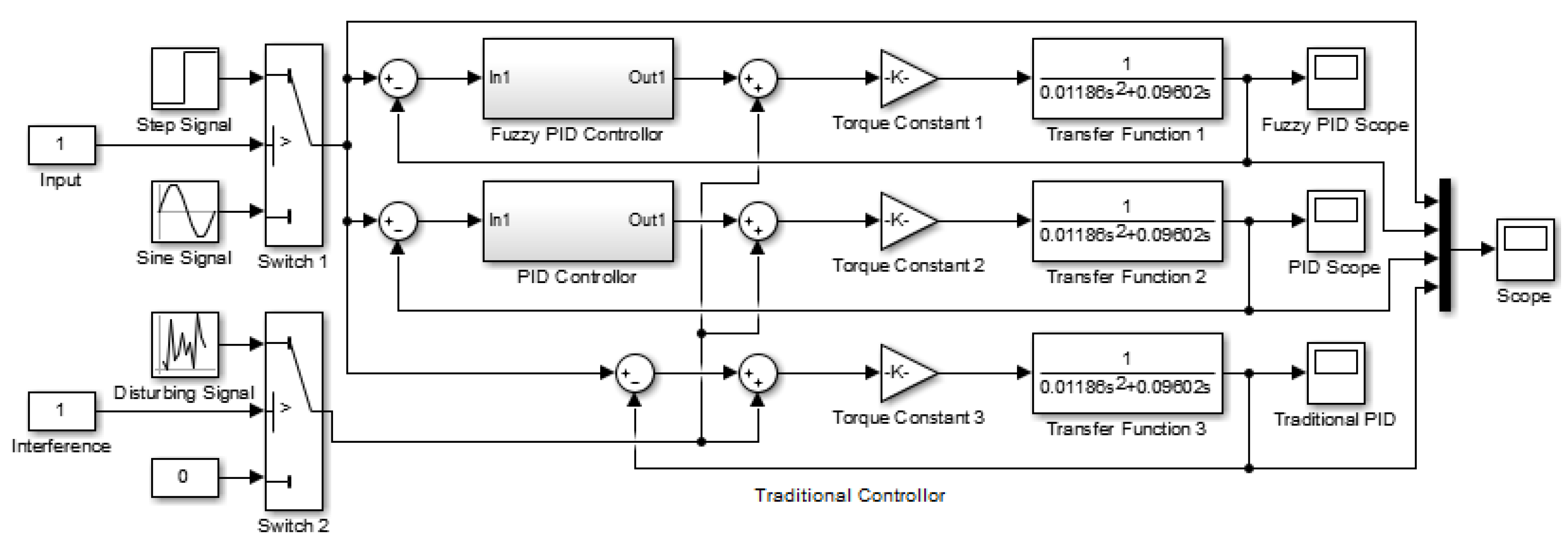
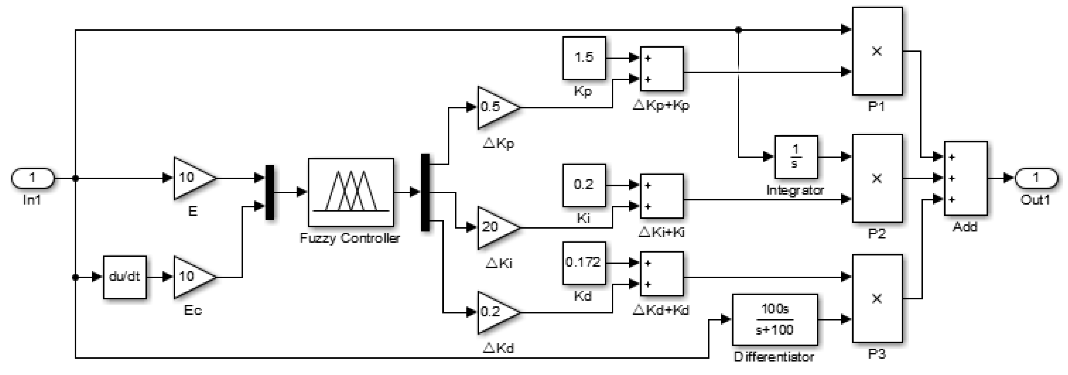
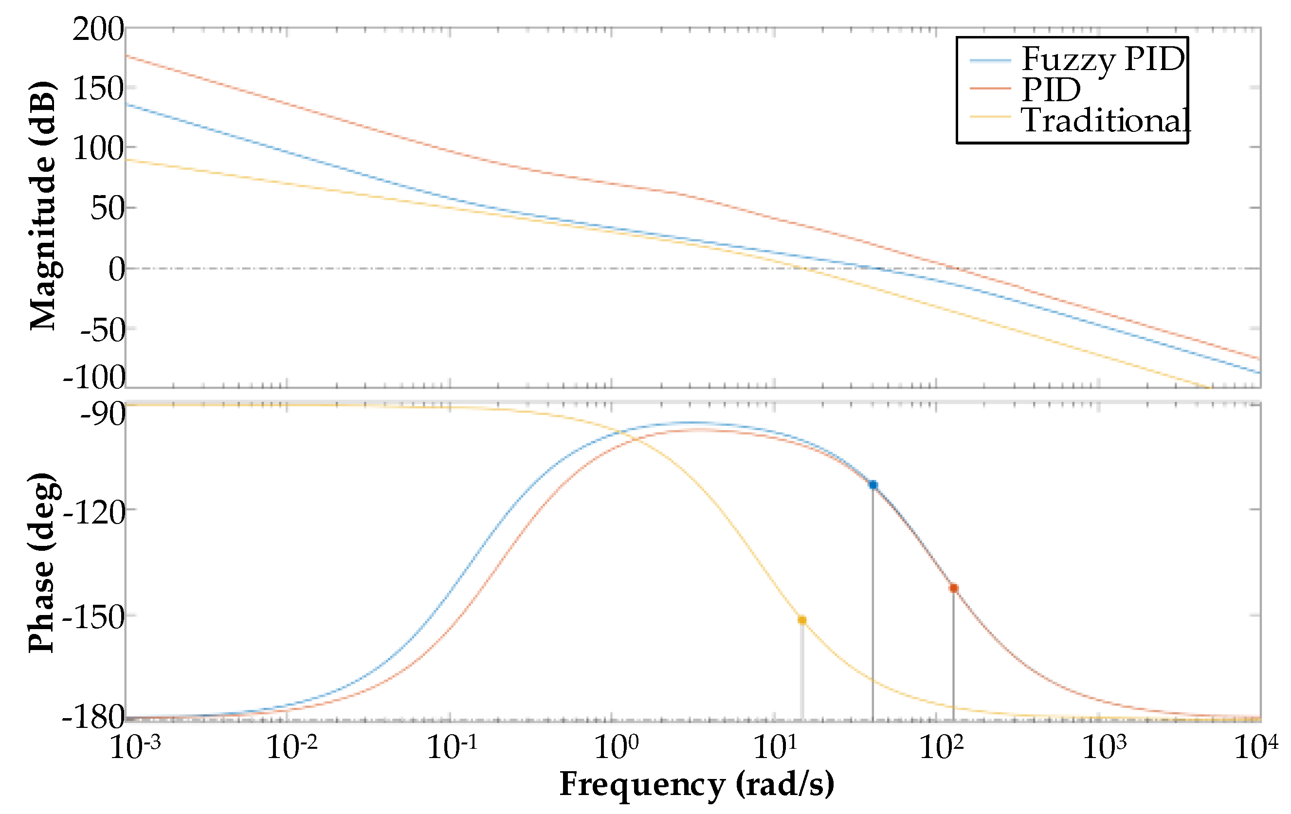
4.3. Control System Simulation

According to the analysis in the first two sections, the fuzzy PID controller in Figure 11 was built through the Simulink environment of MATLAB. The sine and step signals were selected to compare their follow-up performance, and the random interference signals were added to observe their anti-interference ability, as shown in Figure 15.
The Bode diagram of the control system was drawn by MATLAB, and the stability margin was obtained, as shown in Figure 16. The phase margin (PM) of the traditional controller was 28.5°, the PM of the PID controller was 30.7°, and the PM of the fuzzy PID controller was 67.1°. The phase frequency characteristics of the three controllers did not cross the −180° line, so the system must have been stable, and the fuzzy PID controller had the best stability.
The preset signal sampling period was 0.001 s. The response curves of the three controllers under step signals are shown in Figure 17, and the relevant parameters of the controllers are listed in Table 1. It can be seen from Figure 17 and Table 1 that the two-dimensional fuzzy PID controller designed in this paper had a faster response speed, lower oversets and a smaller steady state error than the traditional PID controller under the same interference signal, and it was less affected by the interference signal.

5. Experimental Validation

In order to verify the performance of the designed VISR, first, the anti-interference ability of the fuzzy PID controller was analyzed through experimentation. Then, two experiments were designed to evaluate the force feedback quality of the VISR and its ability to control the clamping force in real time. Finally, the experiments showed that the VISR can safely and effectively assist doctors to deliver the guidewire accurately.

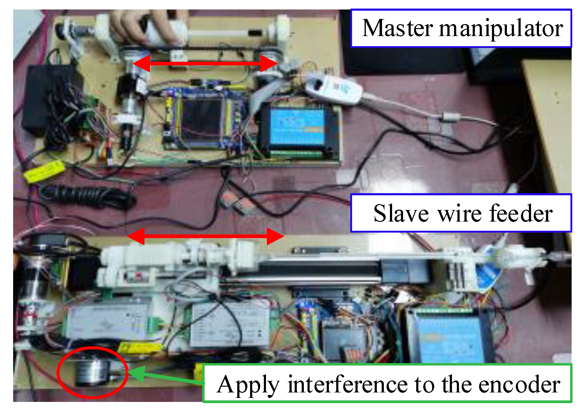
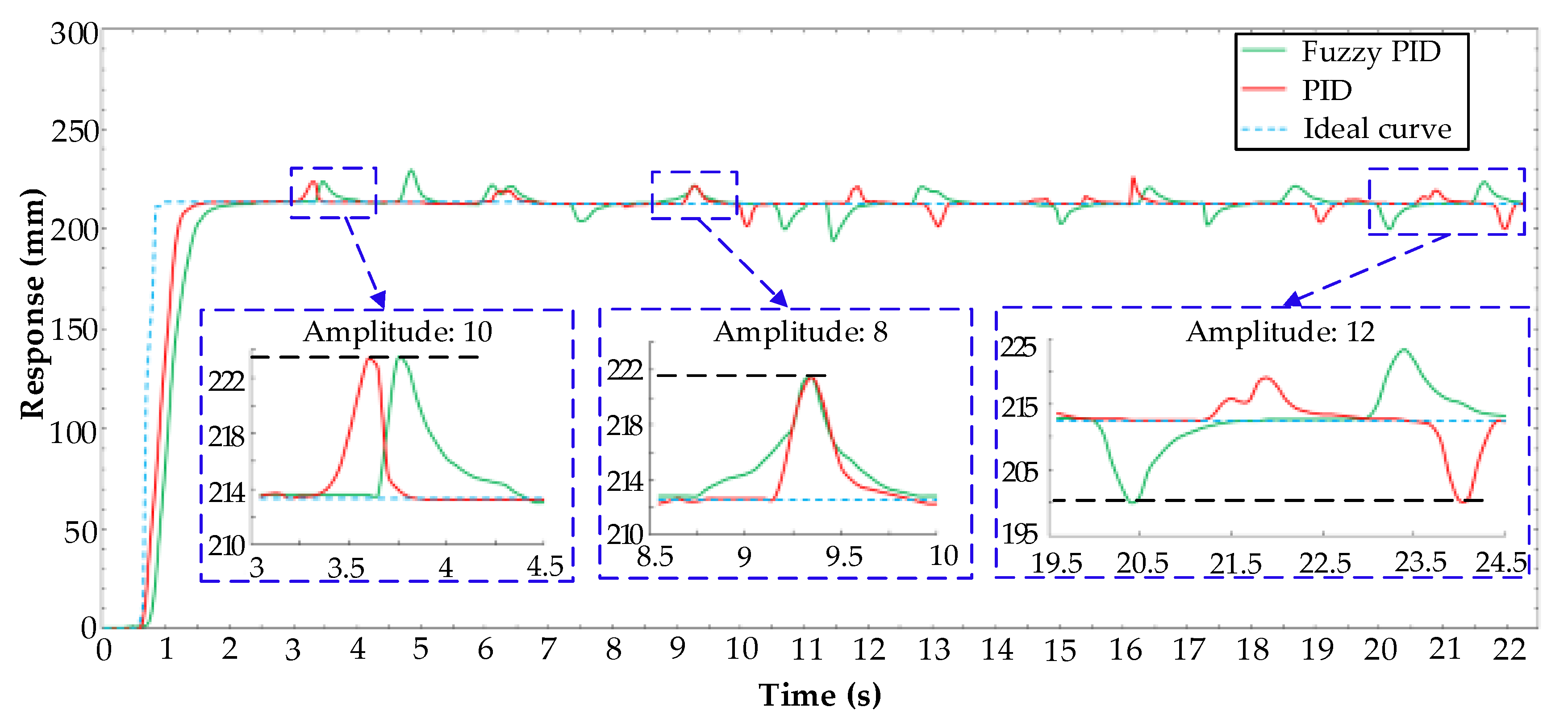
5.1. Fuzzy PID Controller Anti-Interference Experiment

The experimental device is shown in Figure 18. The PID controller and fuzzy PID controller designed in Chapter 4 were used to operate the VISR. The operator pushed the operating handle of the main manipulator, and after the slave wire feeder ran to a predetermined position, random interference was applied to the encoder (related information was introduced in Section 2.2). The response of the system and the time needed to adjust the interference were recorded under the actions of the two controllers. The experimental results are shown in Figure 19.
The analysis showed that that the response speed of the fuzzy PID controller was faster. The conventional PID controller had a maximum amplitude of −18 mm and an average amplitude of 3.45 mm, while the fuzzy PID controller had a maximum amplitude of −13 mm and an average amplitude of 2.37 mm. When the amplitude was −8 mm, the adjustment time of the fuzzy PID controller was 43.75% faster than that of the ordinary PID controller; when the amplitude was −10 mm, it was 42.86% faster; and when the amplitude was −12 mm, it was 46.67% faster. Therefore, the designed fuzzy PID controller had the stronger anti-interference ability.

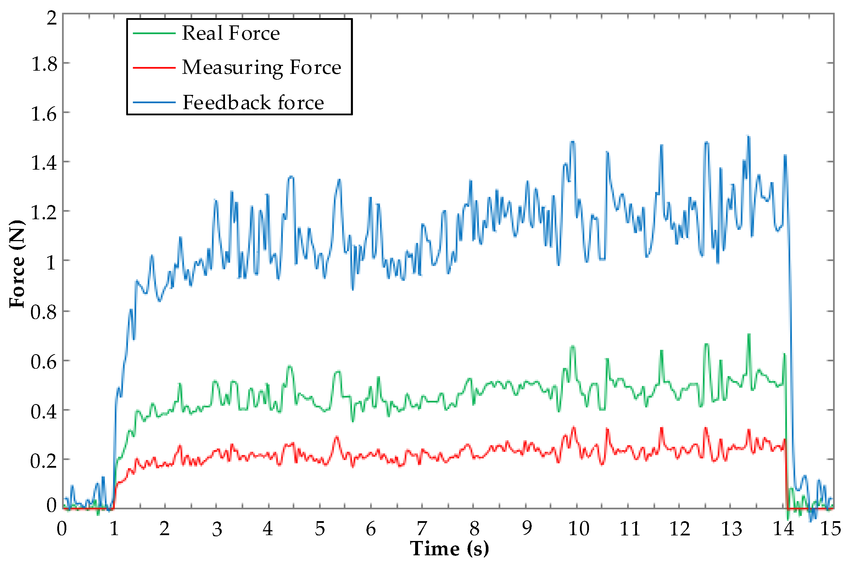
5.2. Force Feedback Experiment

To verify the force feedback capability of the VISR in Section 2.3, a force feedback experiment was conducted, as shown in Figure 20. The slave wire feeder of the VISR was placed horizontally, the guidewire (ATW-595-ME014, Cordis Corporation, Dublin, USA) was passed through the clamping component and extended forward to the front end of the Y-type valve holder, and the sensor bracket was placed directly in front of the Y-type valve holder. The experimental sensor (MDL: SBT674-2 kg, Simbatouch, Guangzhou, CN) was connected to the sensor bracket by the spring, and the axis of the guidewire was kept in a straight line with it. The operator propelled the master manipulator, and the slave wire feeder drove the guidewire to propel the experimental sensor forward, which recorded the force of the guidewire tip. At the same time, the resistance detection mechanism measured the amplified force signal, and the control system adjusted the input excitation current of the magnetic powder clutch according to the force, thus forming a force sensation. The feedback force could be converted according to the excitation current.
By comparing the actual force F 1 of the guidewire, the measured force F 2 of the resistance detection mechanism and the feedback force F 3 of the master manipulator, the quality of the force feedback could be evaluated. In the experiment, the signal sampling period was −50 ms, and the experimental data after processing are shown in Figure 21.
It can be seen that, under the action of a time-varying force, the resistance detection mechanism could accurately detect the actual force of the guidewire and reflect its changing trend. When the guidewire was under force, the resistance detection mechanism could amplify it with the amplification coefficient K 1 , which was determined to be two by the mechanism design. According to the experimental data, the actual coefficient was between 1.86 and 2.17 ( K 1 = F 2 / F 1 ), and the error was less than 8.5%. The control system adjusted the excitation current of the magnetic powder clutch according to the force signal to form a force sensation. The amplification coefficient K 2 could be determined through the design of the algorithm, which was set to 2.5. The actual coefficient was calculated from the experimental data between 2.28 and 2.73 K 2 = F 3 / F 2 , with an error of less than 9.2%.

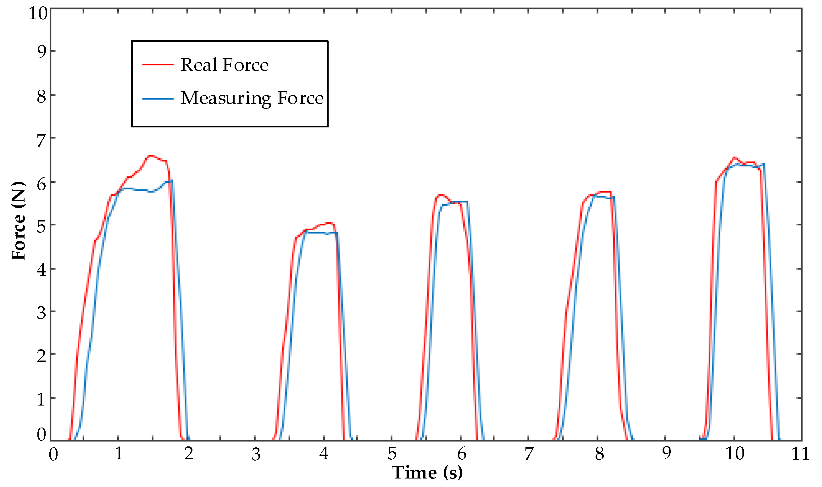
5.3. Clamping Force Experiment

The experiment was conducted to verify the flexible clamping performance of the VISR in Section 2.1 and Section 2.2, as shown in Figure 22. The operator repeatedly pinched and released the film sensor in the operating handle to generate the clamping force signal. The clamping component held the guidewire according to this, and the clamping sensor synchronously recorded the actual clamping force of the guidewire. The operator varied the force overtime and mimicked the trembles for when the doctor was tired. By comparing the force signals measured by the film sensor and the clamping sensor, the performance of the VISR in adjusting the clamping force could be judged. The experimental results are shown in Figure 23.
According to the experimental data, the clamping force could be regulated according to the force given by the operator at the master manipulator. When the operator pressed the sensor, the clamping force quickly approached the peak, and when the operator released the finger, the clamping force rapidly decreased to zero, which indicated that VISR was flexible enough for the clamping of the guidewire. Near the peak of the clamping force, the accuracy rate of the first clamping was 85.4~92.7%, and the accuracy rates of the last four clampings were above 95%. Therefore, it was believed that the actual clamping force of the guidewire was close to the squeezing force given by human hands. When the hand trembled, the VISR could eliminate it to some extent. There was a delay in the system during operation, with the maximum not being more than −50 ms, which was within the acceptable range.

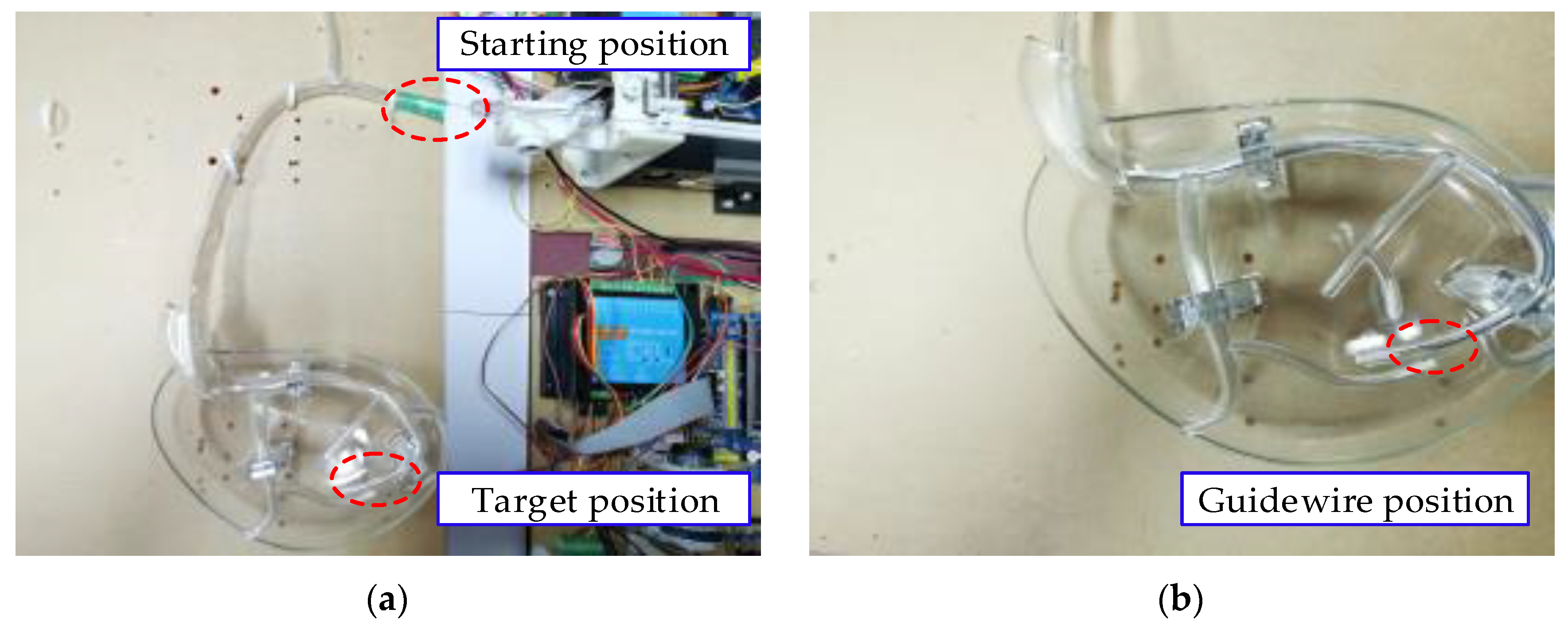
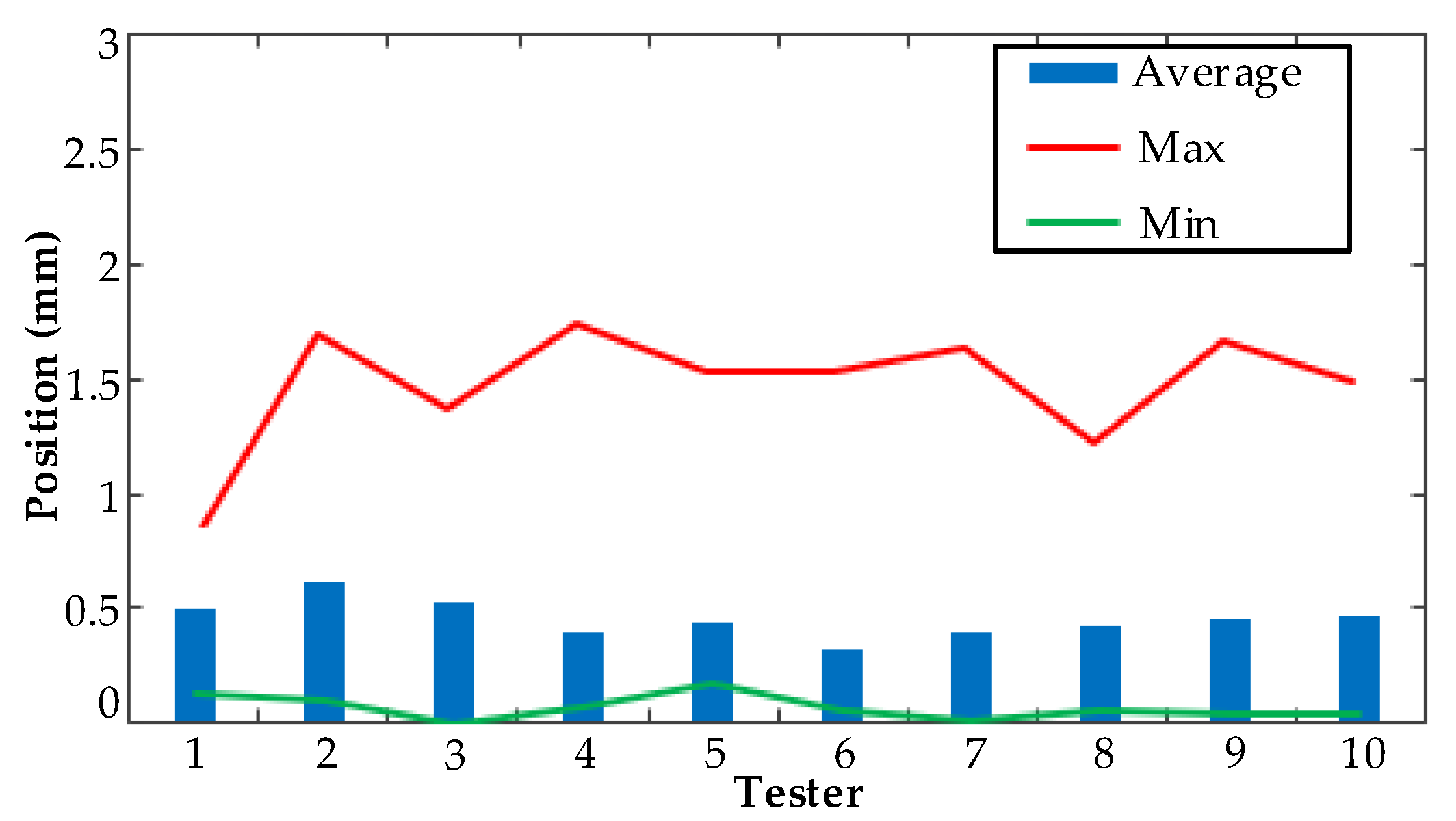
5.4. Vascular Model Experiment

In order to verify whether the designed VISR could effectively assist the doctor in surgery, an experiment was conducted to test whether the guidewire could be successfully propelled to a target position in a human vascular model. The model was designed by the author under the guidance of doctors, and it could simulate the vascular environment of the human body to a certain extent. Ten operators were enrolled to operate the VISR, as shown in Figure 24.
In this experiment, each operator performed ten trials, and the guidewire positions were recorded. The vascular model was measured to be 585 mm from the starting position to the target position, and the actual transmission distance of the guidewire could be obtained by the encoder in the slave wire feeder by taking the absolute value of their difference. The experimental results are shown in Figure 25.
As can be seen from Figure 25, the maximum position error of the ten operators in this experiment was between 0.89–1.45 mm, the minimum error was less than 0.3 mm and the average error of 8 operators was not more than 0.5 mm. In this experiment, the operators judged the position of the guidewire in their eyes, and since they were not professionally trained interventional physicians, the error was mainly caused by the operator itself rather than the VISR. The designed VISR focused on the force feedback and flexible clamping. Even if the amount of guidewire delivery was too large in the actual operation, the force feedback mechanism could avoid the guidewire tip piercing the blood vessel wall. Therefore, it is believed that the designed VISR can safely and effectively assist doctors to deliver the guidewire accurately.

6. Conclusions

This paper introduces a novel vascular interventional surgical robot and its control method, based on force feedback and flexible clamping. The robot is a master–slave system, characterized by flexible clamping, real-time control of the clamping force and the ability to accurately establish force feedback and assist doctors to make judgments on the state of the guidewire tip. The motions of the robot include the clamping, twisting and propulsion of the guidewire. In order to ensure the precision of the propulsive motion and the acquisition of a force signal, a two-dimensional fuzzy PID controller was designed, based on the dynamic model of the system, and a fuzzy control strategy was added. The performance of the VISR was verified by experiments. The experimental results showed that the designed fuzzy PID controller could improve the anti-interference ability of the system by more than 40%. The VISR could accurately measure the proximal force of the guidewire and amplify it, thus forming a force sensation for doctors. Among them, the measurement error was less than 8.5%, and the amplification error was less than 9.2%. The guidewire could be clamped flexibly, and the clamping accuracy rate was about 95%. Therefore, the designed VISR could effectively assist doctors to deliver the guidewire accurately and safely.
However, there are several limitations in this paper. Firstly, the effect of the vascular environment on the force feedback mechanism was not considered in the establishment of the force feedback mechanism. Second, the operator needs to be guided and trained to perform the VISR. Finally, the lag in the master–slave motion needs to be reduced. In the future, we will improve the VISR to overcome the mentioned limitations and verify its performance through related experiments.

Author Contributions

Conceptualization, H.Y. and H.W.; methodology, J.C. and J.N.; software, F.W. and Y.Y.; formal analysis, H.T.; verification, J.F. and H.L.; writing—original draft preparation, H.Y.; writing—review and editing, H.W. All authors have read and agreed to the published version of the manuscript.

Funding

This work was funded by the National Key Research and Development Program of China (2019YFB1311700), National Natural Science Foundation of China (U1713219) and Shanghai Science and Technology Innovation Action Plan (18441900700).

Informed Consent Statement

Not applicable.

Data Availability Statement

Data available in a publicly accessible repository.

Conflicts of Interest

The authors declare no conflict of interest.

References

  1. Sachs, D.; Capobianco, R. Minimally invasive sacroiliac joint fusion: One-year outcomes in 40 patients. Adv. Orthop. 2013, 2013, 536128. [Google Scholar] [CrossRef] [PubMed]
  2. Vitiello, V.; Lee, S.L.; Cundy, T.P.; Yang, G.Z. Emerging robotic platforms for minimally invasive surgery. IEEE Rev. Biomed. Eng. 2013, 6, 111–126. [Google Scholar] [CrossRef] [PubMed]
  3. Yang, X.; Wang, H.; Sun, L.; Yu, H. Operation and force analysis of the guide wire in a minimally invasive vascular interventional surgery robot system. Chin. J. Mech. Eng. 2015, 28, 249–257. [Google Scholar] [CrossRef]
  4. Klein, L.W.; Miller, D.L.; Balter, S.; Laskey, W.; Haines, D.; Norbash, A.; Mauro, M.A.; Goldstein, J.A. Occupational health hazards in the interventional laboratory: Time for a safer environment. Radiology 2009, 250, 538–544. [Google Scholar] [CrossRef] [PubMed]
  5. Whitby, M.; Martin, C.J. A study of the distribution of dose across the hands of interventional radiologists and cardiologists. Br. J. Radiol. 2005, 78, 219–229. [Google Scholar] [CrossRef] [PubMed]
  6. Orme, N.M.; Rihal, C.S.; Gulati, R.; Holmes, D.R., Jr.; Lennon, R.J.; Lewis, B.R.; McPhail, I.R.; Thielen, K.R.; Pislaru, S.V.; Sandhu, G.S.; et al. Occupational health hazards of working in the interventional laboratory: A multisite case control study of physicians and allied staff. J. Am. Coll. Cardiol. 2015, 65, 820–826. [Google Scholar] [CrossRef] [PubMed] [Green Version]
  7. Taylor, R.H.; Stoianovici, D. Medical robotics in computer-integrated surgery. IEEE Trans. Robot. Autom. 2003, 19, 765–781. [Google Scholar] [CrossRef]
  8. Yu, H.; Wang, H.; Zhang, W.; Liu, H.; Chang, J.; Huang, D. Master-slave system research of a vascular interventional surgical robot. In Proceedings of the 2018 IEEE International Conference on Real-time Computing and Robotics, Kandima, Maldives, 1–5 August 2018; pp. 469–473. [Google Scholar]
  9. Haidegger, T. Autonomy for surgical robots: Concepts and paradigms. IEEE Trans. Med. Robot. Bionics 2019, 1, 65–76. [Google Scholar] [CrossRef]
  10. Weisz, G.; Metzger, D.C.; Caputo, R.P.; Delgado, J.A.; Marshall, J.J.; Vetrovec, G.W.; Reisman, M.; Waksman, R.; Granada, J.F.; Novack, V.; et al. Safety and feasibility of robotic percutaneous coronary intervention: Precise (percutaneous robotically-enhanced coronary intervention) study. J. Am. Coll. Cardiol. 2013, 61, 1596–1600. [Google Scholar] [CrossRef] [Green Version]
  11. Di Biase, L.; Wang, Y.; Horton, R.; Gallinghouse, G.J.; Mohanty, P.; Sanchez, J.; Patel, D.; Dare, M.; Canby, R.; Price, L.D.; et al. Ablation of atrial fibrillation utilizing robotic catheter navigation in comparison to manual navigation and ablation: Single-center experience. J. Cardiovasc. Electrophysiol. 2009, 20, 1328–1335. [Google Scholar] [CrossRef]
  12. Kanagaratnam, P.; Koa-Wing, M.; Wallace, D.T.; Goldenberg, A.S.; Peters, N.S.; Davies, D.W. Experience of robotic catheter ablation in humans using a novel remotely steerable catheter sheath. J. Interv. Card. Electrophysiol. 2008, 21, 19–26. [Google Scholar] [CrossRef] [PubMed] [Green Version]
  13. Iyengar, S.; Gray, W.A. Use of magnetic guidewire navigation in the treatment of lower extremity peripheral vascular disease: Report of the first human clinical experience. Catheter. Cardiovasc. Interv. 2009, 73, 739–744. [Google Scholar] [CrossRef] [PubMed]
  14. Rafii-Tari, H.; Payne, C.J.; Yang, G.Z. Current and emerging robot-assisted endovascular catheterization technologies: A review. Ann. Biomed. Eng. 2014, 42, 697–715. [Google Scholar] [CrossRef] [PubMed]
  15. Tercero, C.; Ikeda, S.; Uchiyama, T.; Fukuda, T.; Arai, F.; Okada, Y.; Ono, Y.; Hattori, R.; Yamamoto, T.; Negoro, M.; et al. Autonomous catheter insertion system using magnetic motion capture sensor for endovascular surgery. Int. J. Med. Robot. 2007, 3, 52–58. [Google Scholar] [CrossRef]
  16. Thakur, Y.; Bax, J.S.; Holdsworth, D.W.; Drangova, M. Design and performance evaluation of a remote catheter navigation system. IEEE. Trans. Biomed. Eng. 2009, 56, 1901–1908. [Google Scholar] [CrossRef]
  17. Swaminathan, R.V.; Rao, S.V. Robotic-assisted transradial diagnostic coronary angiography. Catheter. Cardiovasc. Interv. 2018, 92, 54–57. [Google Scholar] [CrossRef]
  18. Carrozza, J.P., Jr. Robotic-assisted percutaneous coronary intervention--filling an unmet need. J. Cardiovasc. Transl. Res. 2012, 5, 62–66. [Google Scholar] [CrossRef]
  19. Maor, E.; Eleid, M.F.; Gulati, R.; Lerman, A.; Sandhu, G.S. Current and future use of robotic devices to perform percutaneous coronary interventions: A review. J. Am. Heart Assoc. 2017, 6, 1–8. [Google Scholar] [CrossRef]
  20. Woo, J.; Song, H.-S.; Cha, H.-J.; Yi, B.-J. Advantage of steerable catheter and haptic feedback for a 5-DOF vascular intervention robot system. Appl. Sci. 2019, 9, 4035. [Google Scholar] [CrossRef] [Green Version]
  21. Tavallaei, M.A.; Gelman, D.; Lavdas, M.K.; Skanes, A.C.; Jones, D.L.; Bax, J.S.; Drangova, M. Design, development and evaluation of a compact telerobotic catheter navigation system. Int. J. Med. Robot 2016, 12, 442–452. [Google Scholar] [CrossRef] [Green Version]
  22. Bao, X.; Guo, S.; Xiao, N.; Li, Y.; Yang, C.; Shen, R.; Cui, J.; Jiang, Y.; Liu, X.; Liu, K. Operation evaluation in-human of a novel remote-controlled vascular interventional robot. Biomed. Microdevices 2018, 20, 34. [Google Scholar] [CrossRef] [PubMed]
  23. Tian, Y.; Xu, L.; Liu, J.; Wang, W.; Liu, L.; Xu, Z.; Li, L. Research on motion signal capture accuracy of master manipulator for vascular interventional robot. J. Adv. Mech. Des. Syst. Manuf. 2018, 12, 1–12. [Google Scholar] [CrossRef] [Green Version]
  24. Yin, X.; Guo, S.; Xiao, N.; Tamiya, T.; Hirata, H.; Ishihara, H. Safety operation consciousness realization of a MR fluids-based novel haptic interface for teleoperated catheter minimally invasive neuro surgery. IEEE ASME Trans. Mechatron. 2016, 21, 1043–1054. [Google Scholar] [CrossRef]
  25. Zhou, J.; Mei, Z.; Miao, J.; Mao, J.; Wang, L.; Wu, D.; Sun, D.; Zhao, Y. A remote-controlled robotic system with safety protection strategy based on force-sensing and bending feedback for transcatheter arterial chemoembolization. Micromachines 2020, 11, 805. [Google Scholar] [CrossRef]
  26. Omisore, O.M.; Han, S.; Ren, X.; Wang, S.; Ou, F.; Li, H.; Wang, L. Towards characterization and adaptive compensation of backlash in a novel robotic catheter system for cardiovascular interventions. IEEE Trans. Biomed. Circuits Syst. 2018, 12, 824–838. [Google Scholar] [CrossRef]
  27. Bao, X.; Guo, S.; Xiao, N.; Li, Y.; Shi, L. Compensatory force measurement and multimodal force feedback for remote-controlled vascular interventional robot. Biomed. Microdevices 2018, 20, 74. [Google Scholar] [CrossRef]
  28. Cha, H.J.; Yi, B.J.; Won, J.Y. An assembly-type master-slave catheter and guidewire driving system for vascular intervention. Proc. IMechE Part H J. Eng. Med. 2017, 231, 69–79. [Google Scholar] [CrossRef]
  29. Shen, H.; Wang, C.; Xie, L.; Zhou, S.; Gu, L.; Xie, H. A novel remote-controlled robotic system for cerebrovascular intervention. Int. J. Med. Robot. Comput. Assist. Surg. 2018, 14, e1943. [Google Scholar] [CrossRef]
  30. Bao, X.; Guo, S.; Xiao, N.; Li, Y.; Yang, C.; Jiang, Y. A cooperation of catheters and guidewires-based novel remote-controlled vascular interventional robot. Biomed. Microdevices 2018, 20, 20. [Google Scholar] [CrossRef]
Figure 1. Schematic diagram of the system.
Applsci 11 00611 g001
Figure 2. Virtual prototype of the master manipulator.
Applsci 11 00611 g002
Figure 3. Virtual prototype (a) and section view (b) of the operation handle.
Applsci 11 00611 g003
Figure 4. Virtual prototype of a slave wire feeder.
Applsci 11 00611 g004
Figure 5. Moving component.
Applsci 11 00611 g005
Figure 6. Clamping component.
Applsci 11 00611 g006
Figure 7. Force perception feedback system.
Applsci 11 00611 g007
Figure 8. Resistance detection mechanism.
Applsci 11 00611 g008
Figure 9. Motion diagram of propulsion.
Applsci 11 00611 g009
Figure 10. Motion diagram of rotation.
Applsci 11 00611 g010
Figure 11. Control system comparison schematic.
Applsci 11 00611 g011
Figure 12. Conventional PID controller.
Applsci 11 00611 g012
Figure 13. Principle of a two-dimensional fuzzy controller.
Applsci 11 00611 g013
Figure 14. The fuzzy control surface of the outputs Δ k p (a), Δ k i (b) and Δ k d (c).
Applsci 11 00611 g014
Figure 15. Fuzzy PID controller.
Applsci 11 00611 g015
Figure 16. Bode diagram of the control system.
Applsci 11 00611 g016
Figure 17. The response of the step signal.
Applsci 11 00611 g017
Figure 18. Anti-interference experimental device.
Applsci 11 00611 g018
Figure 19. The responses of the two controllers to interference signals.
Applsci 11 00611 g019
Figure 20. Force feedback experiment principle (a) and device (b).
Applsci 11 00611 g020
Figure 21. Force feedback data.
Applsci 11 00611 g021
Figure 22. Film sensor (a) in the operating handle and the clamping sensor (b) in the clamping component.
Applsci 11 00611 g022
Figure 23. Clamping force data.
Applsci 11 00611 g023
Figure 24. Human vascular model (a) and guidewire position (b).
Applsci 11 00611 g024
Figure 25. Guidewire position error.
Applsci 11 00611 g025
Table 1. Controller performance parameters table.
ControllerRise Time (s)Maximum Deviation (mm)Mean Deviation (mm)
Traditional controller0.440.37780.1153
PID controller0.130.12220.0724
Fuzzy PID controller0.120.04000.0147
Publisher’s Note: MDPI stays neutral with regard to jurisdictional claims in published maps and institutional affiliations.

