Article

Railway Axle and Wheel Assembly Press-Fitting Force Characteristics and Holding Torque Capacity

Department of Mechanical Engineering, School of Engineering, King Mongkut’s Institute of Technology, Ladkrabang, Bangkok 1052, Thailand
*
Author to whom correspondence should be addressed.
Appl. Sci. 2021, 11(19), 8862; https://doi.org/10.3390/app11198862
Submission received: 11 August 2021 / Revised: 15 September 2021 / Accepted: 16 September 2021 / Published: 23 September 2021

Abstract

:
Nowadays, press-fitting is widely used in the manufacturing industry because it allows easy and fast installation and is repetitive, strong, and inherently reliable. The quality of a press-fitting assembly can be verified from the press-fitting curves and forced monitoring. This study aims to investigate the characteristics of the press-fitting curve with various interference railway wheelset models and determine the interference limit that axles can withstand at the maximum holding torque without slipping and without plastic deformation. A three-dimensional finite element analysis examined the maximum press-fitting force and stress distributions using Abaqus FEA software. The press-fitting curves of the railway wheel and axle assembly obtained from finite element simulation were classified following European Standard EN 13260. The press-fitting curves showed whether they fell within the boundary limits in the EN standard to allow their practical application. This study also showed when plastic deformation would occur, within the recommended interferences in the EN standard. Moreover, the effect of interference was numerically simulated for the maximum holding torque capacity within the EN standard interference range. Numeric simulation was compared with the theory: the deviation was 15–6%.

1. Introduction

A railway wheelset is an assembly consisting of an axle and two wheels fitted with interference and, where necessary, applicable associated components, e.g., gear-shaft, bearing bushing, etc. Wheelsets need to be safe because failures could lead to derailment and potentially to major safety issues, including loss of life and heavy damage to railway vehicles. Therefore, it is important to assemble the wheelset correctly to reduce accidents and derailments. Wheelsets are assembled to remain attached to all components while in operation. Wheels may be press-fitted or shrink-fitted to the axles. Press-fit, or interference fit, tightens two parts together by relying on friction and joining the parts that can take a different form. This is commonly used in the industry because the process is reliable, simple, and does not require heating, cooling, or soldering. One problem with railway wheelsets is their failure due to excessive interference in press-fitting, and this can result in a slip between the wheel and axle. Fretting wear takes place at the interface of the axle wheel seat and the wheel hub surface, and it can cause surface fatigue, adhesion, oxidation, exfoliation, and scratching [1,2]. If a press-fit is used for assembling the wheels onto the axle, the wheel mounting peak press force limits and the press-fitting curve must be considered. Furthermore, many standards have been defined for railway wheelset assembly; for example, JIS E 4504 [3], EN 13260 [4], ISO 100-5 [5], and AAR [6]. Railways tend to follow national standards, so the authors followed the State Railway of Thailand’s practice and used the European standard EN 13260 for the assembly of wheels and axles [4]. Following the standard improves the quality of the wheelset, and this would also help to standardise production.
Very few publications were found in the literature that discussed the characteristics of the press-fitting curve for railway wheelsets. Benuzzi and Donzella analysed the contact pressure and speed related to lubrication and predicted a press-fitting curve using an FEM model and a simplified theoretical model [7]. Lu et al. constructed and tested a mathematical model for the press-fit curve based on the AAR standard [8]. Saad et al. predicted the residual stress and plastic strain for forging, machining, and assembling [9]. Stamenković et al. addressed the effect of the strength of the wheelset press-fit joint and recommended a frictional coefficient value that resisted sliding between the interface for specific conditions by comparing experiment and theory [10]. Michnej and Guzowski investigated fretting wear in a wheelset press-fit joint and conducted contact surface and fretting wear tests; they found that the adhesion phenomenon played a critical part in the initiation of fretting wear in a press-fit joint [11]. Booker and Truman reviewed the factors affecting the interference fit joints’ strength and discussed the modelling and limitations related to the friction coefficient, boundary condition, geometry, and material [12]. Zhao et al. have also discussed the relationship of radial interference and holding torque capacity, the friction coefficient of camshaft based on the finite element analysis and experiment [13].
Lame’s equation can also be used to determine the contact pressures at the interface of the assembly parts and to estimate the maximum holding torque capacity of a press-fit. A major challenge of press-fit assembly is to choose reasonable interference values that would ensure the safety of the assembled components. Too large an interference may damage the part being assembled, and less resistance may result in plastic deformation. To prevent slipping, the wheelset maximum holding torque capacity must be known. The magnitude of the press fit-force depends on the geometry, friction coefficient, material properties, and operating conditions [14].
With this in mind, the authors studied the effects of interference on the press-fitting force because it is important to predict the pressing quality of the wheel and axle assembly. The stress on the axle wheel seat contact area was analysed using simulation, and the state of the stress–strain effects are discussed. Moreover, the interferences needed for wheelset press-fitting without slipping were determined. The press-fitting curve, maximum press-fit force, and maximum holding torque capacity were evaluated using the finite element method using Abaqus FEA software [15].

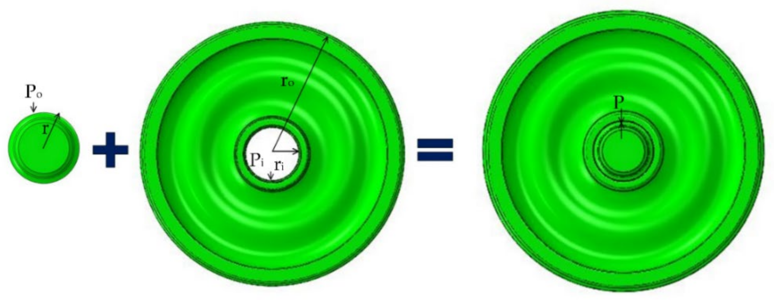
2. Theoretical Analysis of Press-Fitting

In general, wheels and axles should meet the geometric requirements before being assembled, as defined in EN 13261 for axles and EN 13262 for wheels [16,17]. The wheelset can be formed by press-fitting or shrink-fitting. In press-fitting, pressure is applied to the wheel hub to force it onto a slightly larger diameter axle, thus leading to contact. External pressure acts on the axle wheel seat, and the internal pressure acts on the wheel hub (Figure 1).
Pi and Po are equal and opposite at the contact surface in the wheelset because it is assumed that the axle and wheel are composed of the same material. Lame’s equation for contact pressure distribution in thick-walled cylinders [18] was used for calculating the contact pressure, P.
P = E δ 2 r 3 ( r o 2 r 2 ) ( r 2 r i 2 ) ( r o 2 r i 2 )
Equation (1) shows that the contact pressure depends on the interference, δ; nominal diameter, d; inner diameter of the axle, ri; outer diameter of the wheel, ro; and Young’s modulus of elasticity, E. The wheel and axle were idealized as thick-walled cylinders, and the wheel was divided into five sections (Figure 2). The average contact pressure was calculated using Equation (2).
P ¯ = i = 1 N P i L i i = 1 N L i

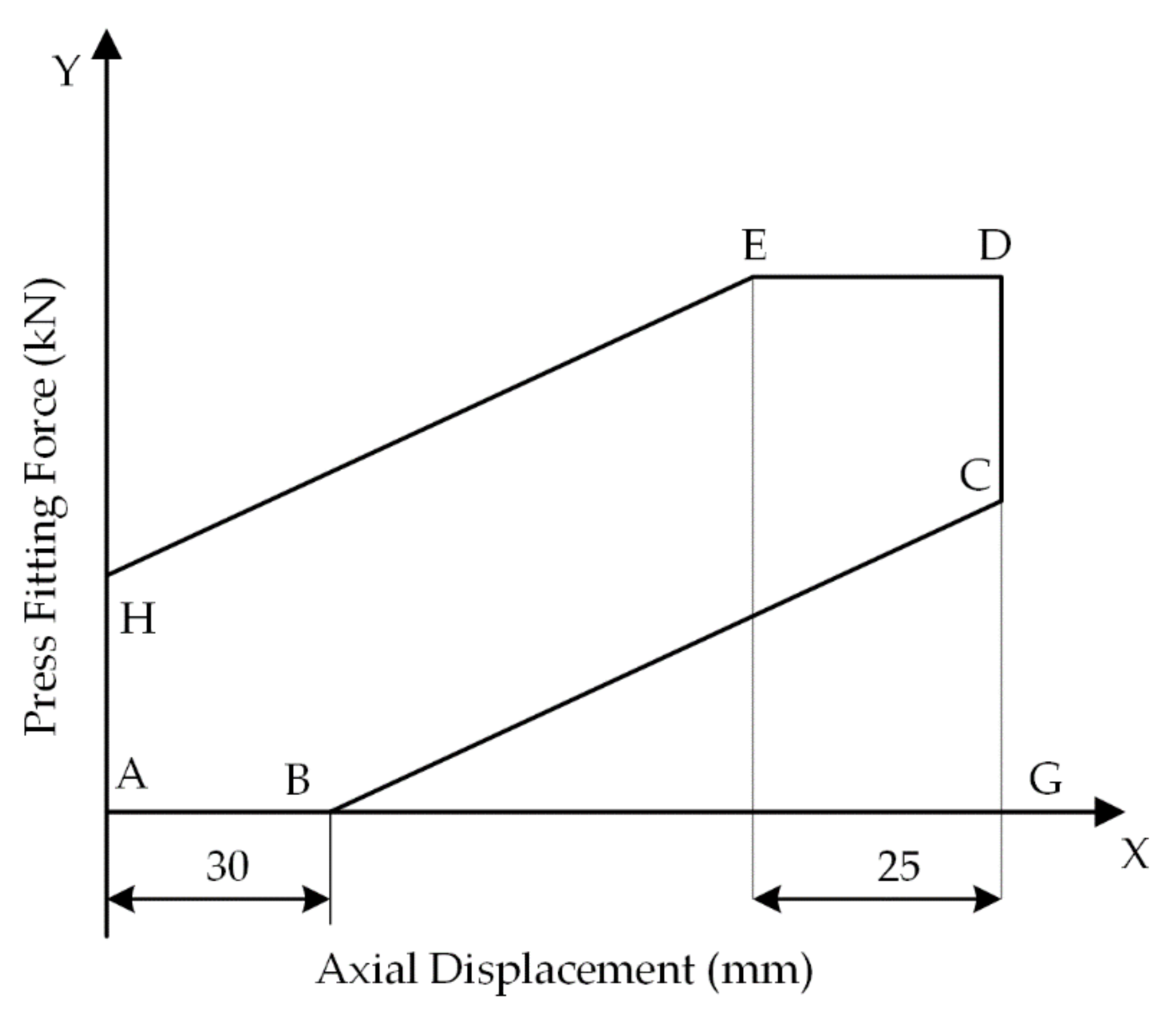
2.1. Characteristics of the Press-Fitting Curve

EN 13260 specified that the interference for press-fitting should be 0.2–0.36 mm, which was based on the geometric tolerances of the axle wheel seats. The factors that mainly influenced the maximum press-fitting force and characteristics of the press-fitting curve were the geometry, coefficient of friction, material strength, and operating conditions. During press-fitting, the wheelset could be damaged by insufficient or excessive press-fitting force. Therefore, the press-fitting curve is very important to determine that the assembly has not been damaged along the contact surfaces. If the press-fitting curve is not within the limits specified in the standard, the wheelset needs to be reassembled or rejected. Figure 3 depicts a press-fitting curve, showing the fitting force versus the displacement. In general, this displacement is the axial displacement of a wheel since the axle is fixed to the clamping head of a machine The standard requires that the final fitting force lies in the range [4]
0.85 F < Final Fitting Force < 1.45 F
The axial force, F, in kN is
F = 4 d
where d is the mean diameter of the axle wheel seat (mm), and L is the axial displacement of the fitting (mm), which must be within the range
0.8 d < L < 1.1 d
The lines, AB, BC, HE, and ED define the boundaries of the press-fitting curve. The contact length is the X-axis, AG, in the diagram. The points labelled in Figure 3 can be found by using the following equations:
  • YH = 1.3 ϕ;
  • YC = 0.85 F;
  • YD = YE = 1.45 F;
where ϕ is the nominal diameter of the wheel seat in millimetres.

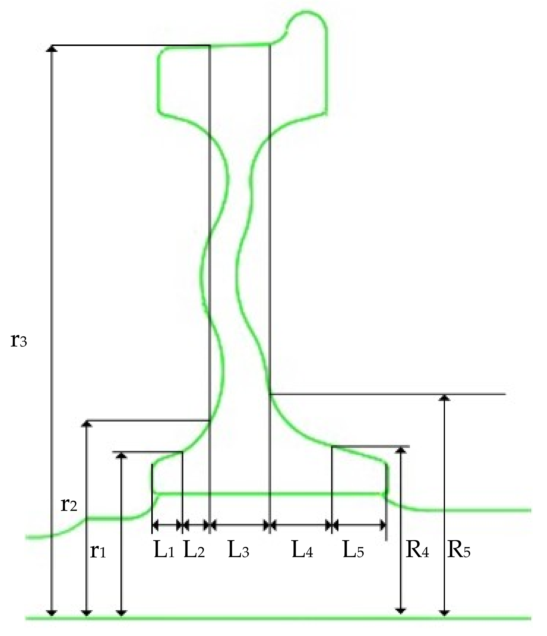
2.2. Determination of the Press-Fitting Force

The press-fitting force is related to many factors, including interference, friction coefficient, and elasticity of the assembled parts. These factors could significantly change the press-fitting force. The press-fitting force to the wheel on the axle, Fp, can be calculated from
F p = μ A P d A
where P = contact pressure (N/m2), µ = coefficient of friction, and A = contact surface area (m2). Thus, to obtain the press-fit force, the contact pressure between the two assembly parts must be known.

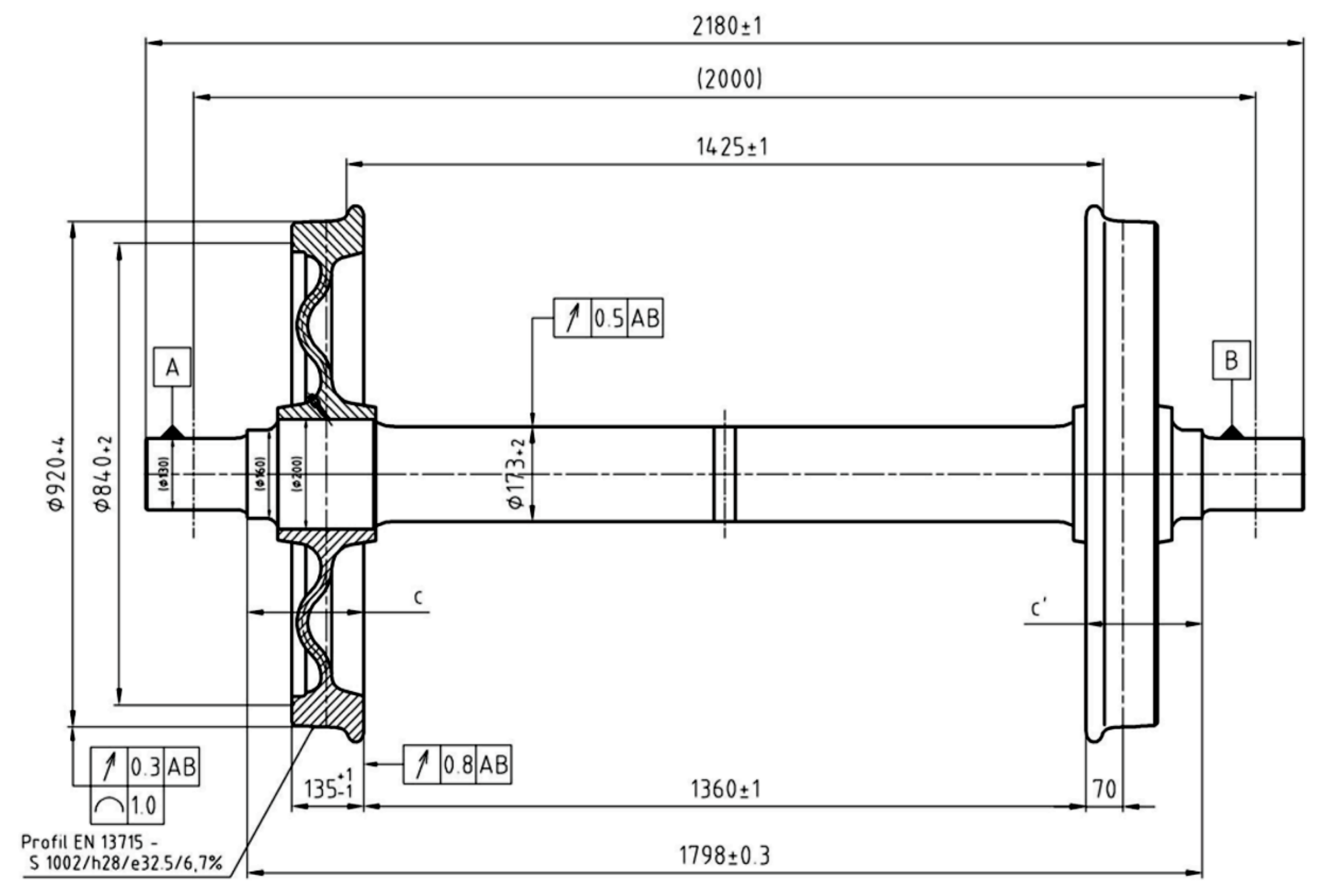
3. Finite Element Modelling and Simulation
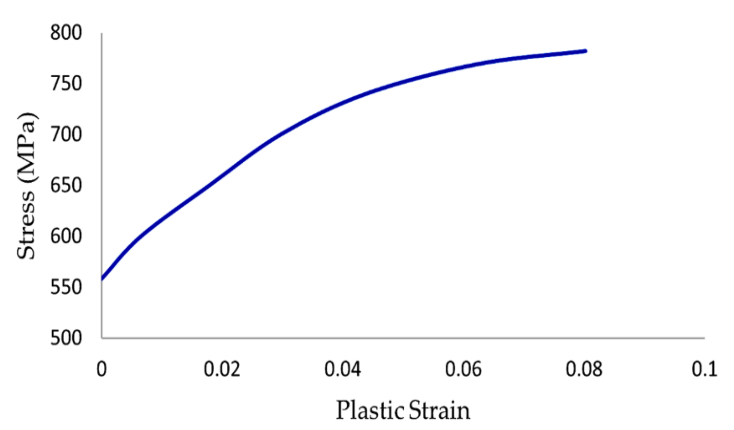
3.1. Materials

Following the EN standard, the EA1N and EA4T steel grades are widely used for railway axles. The chemical composition and mechanical characteristics of EA4T steel are in Table 1 and Table 2. The materials of the wheel and axle were the same, homogeneous, and isotropic, with ideal elastic-plastic behaviour. The stress versus plastic strain graph for EA4T steel is shown in Figure 4.

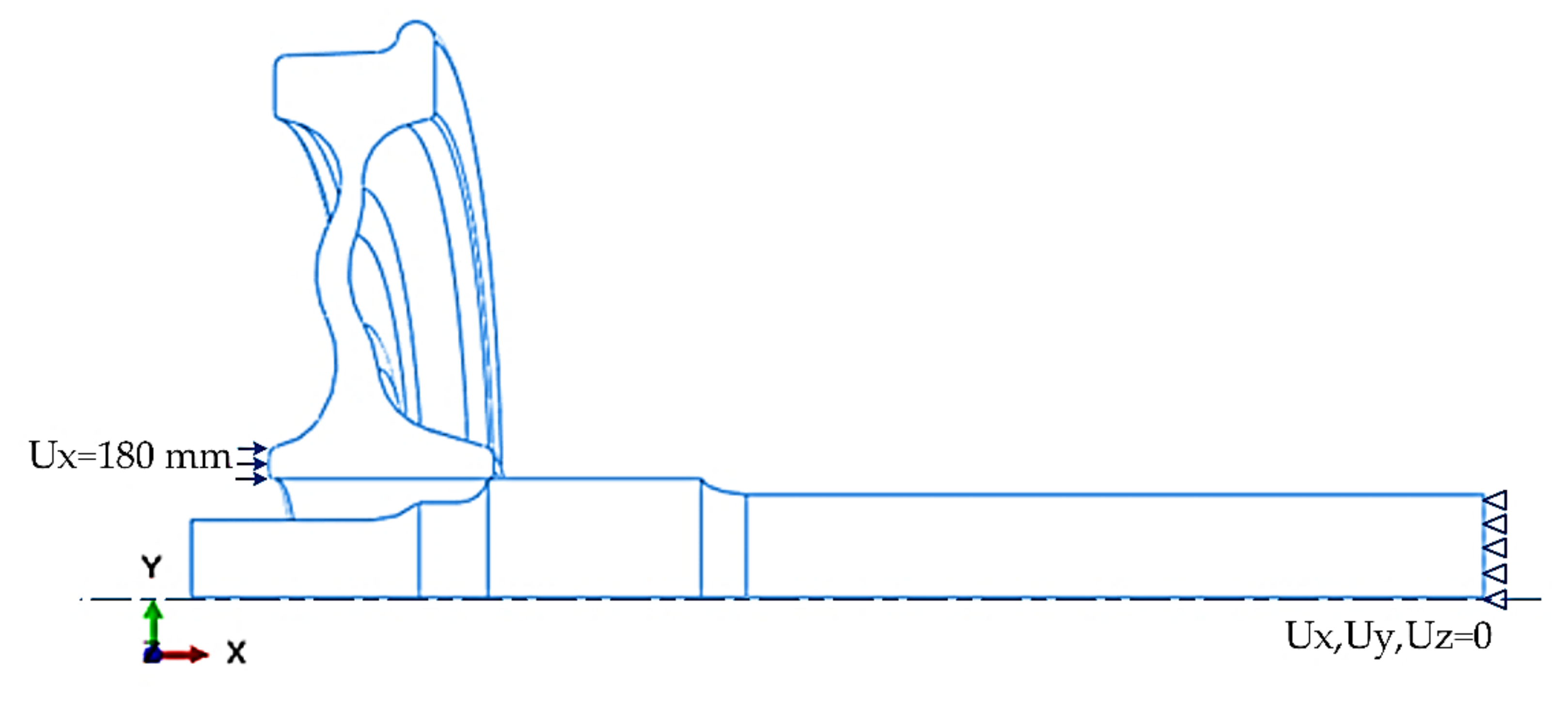
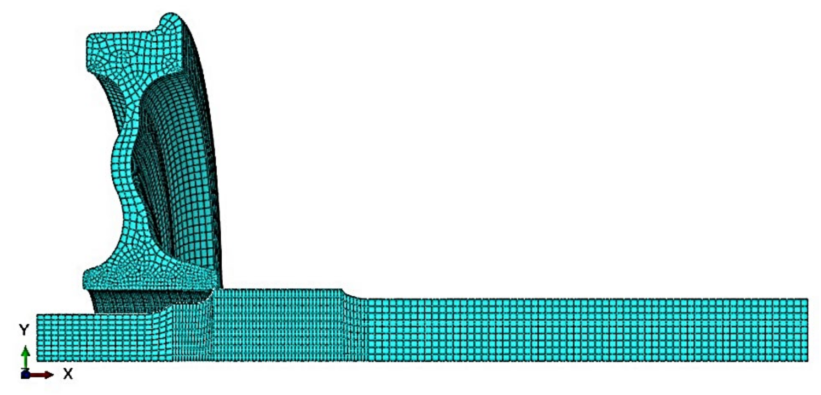
3.2. Modelling and Simulation

To determine the press-fitting force, a quarter 3D model of the wheel and axle assembly, their dimensions given in Figure 5, was made using Abaqus FEA (Figure 6). During assembly, the wheel was moved onto the axle wheel seat by a specialized assembly machine so that interference between the assembly was eliminated for the outer diameter of the axle wheel seat, which was larger than the inner diameter. A static structure was analysed, and the boundary conditions were used in the finite element analysis. Taking advantage of the symmetric boundary conditions, the XY and XZ planes were constrained in the finite element model. The end of the axle was fixed, and an axial displacement, 180 mm, was applied to the wheel hub towards the axle wheel seat. A contact pair was defined between the wheel- and axle-contacting surfaces. This analysis determined the press-fitting force and stress distribution at the contact surface between the wheel and axle. A 2 mm mesh was used for the contact surface of the wheelset, and a 10 mm mesh was used for the other surfaces (see Figure 7). The mesh type was a 20-node quadratic brick, reduced integration (C3D20R); 17,402 elements were used for the axle model, and 51,858 elements were used for the wheel model.

4. Results and Discussion

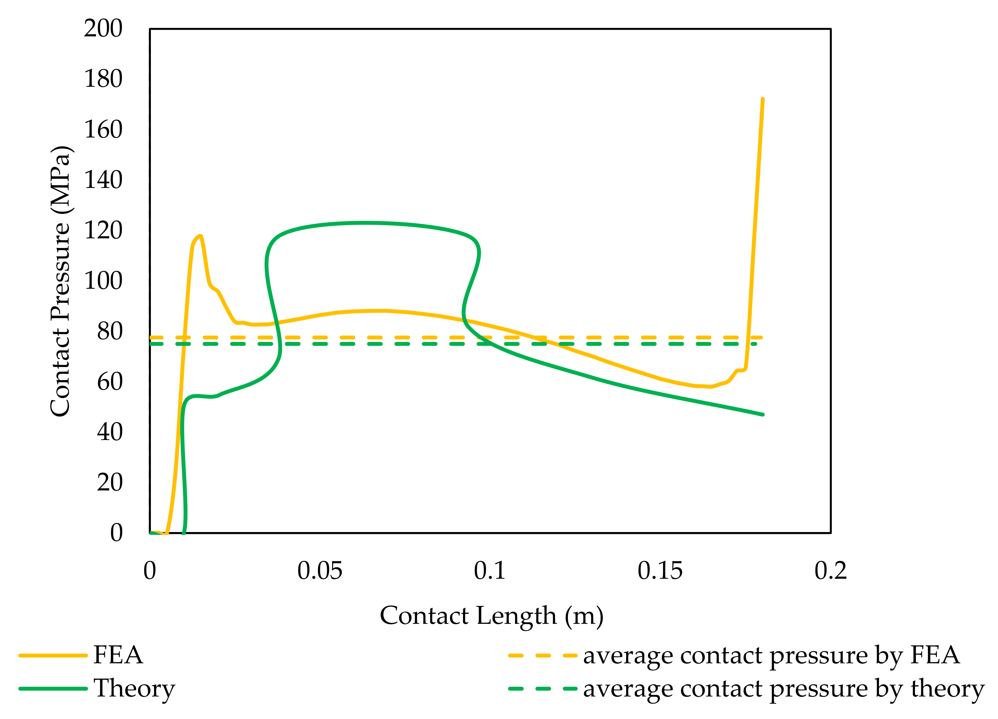
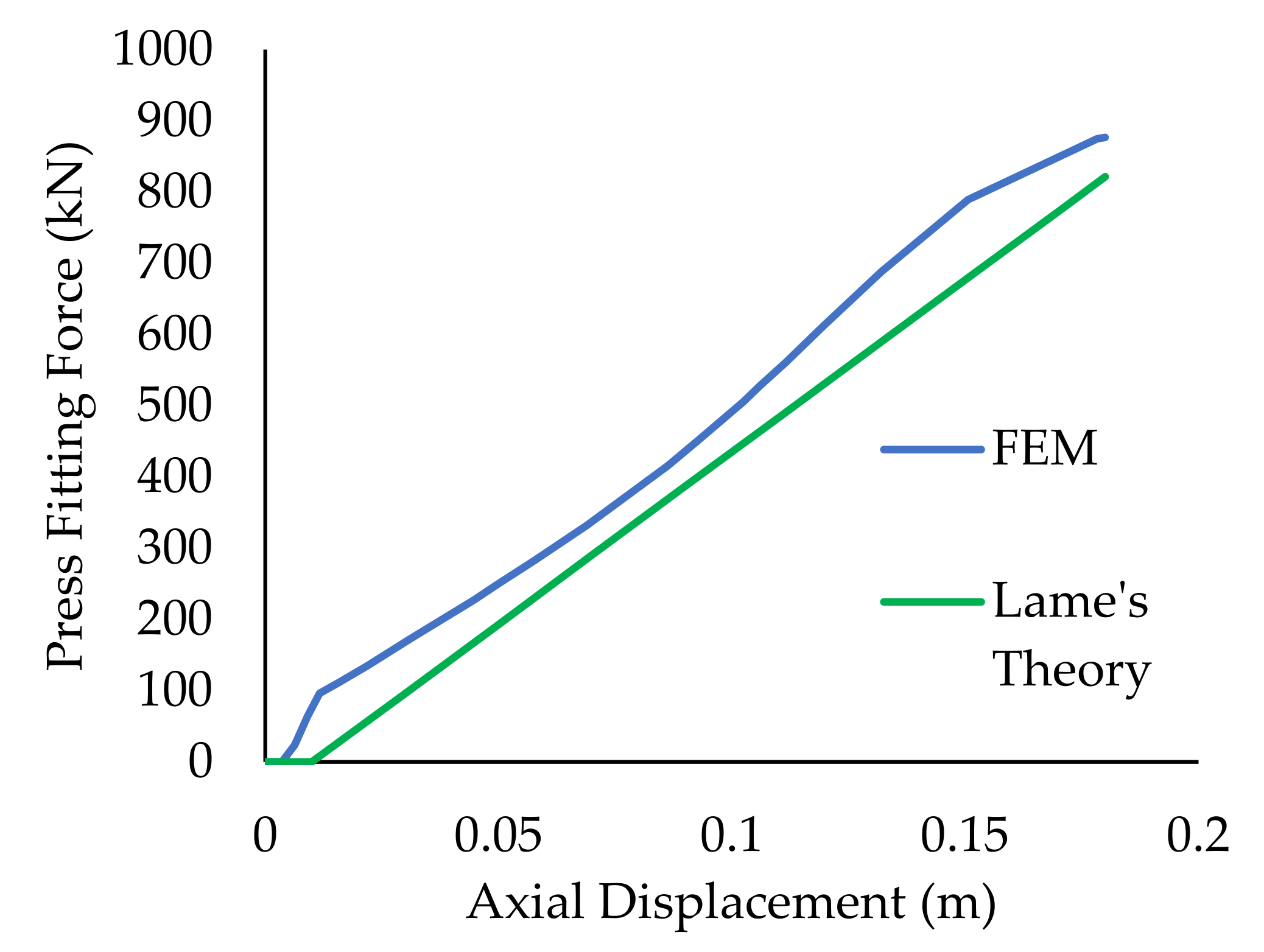
4.1. Comparison between the FEA and Theoretical Results

To verify the effectiveness of the numeric model, the finite element results were compared with the calculated theoretical results. The contact pressure between the wheel and axle wheel seat at different sections was determined from Equation (1), and the average contact pressure was calculated by Equation (2). The contact pressure of the axle reached its maximum at the end of the contact edge. The distribution of the contact pressure and average contact pressure along the contact length of the wheelset is shown in Figure 8. The finite element analyses led to higher average contact pressure than the theoretical model because the volume of the 3D model used in the finite element simulation was greater than that of the theoretical model: the finite element results were 3% greater than the theoretical ones. At the start of the wheelset assembly, the two parts did not contact each other because of the taper of the axle. Therefore, the press-fitting force and contact pressure were zero until the end of the taper was reached, and then they suddenly increased. The theory showed that the contact pressure was directly proportional to the outer radius or profile of the wheel and increased in the centre of the contact region. The contact pressure of the axle increased sharply at the start of the contact and decreased towards the centre of the contact length and maximum at the rear end of the edge. The press-fitting force was calculated from the contact length using Equation (4). Figure 9 compares the finite element and theoretical results. The maximum press-fitting force at the end of the assembly was 877 kN from the finite element analysis and 822 kN from the theory, when the interference was 240 µm. The 7% difference between the results was considered acceptable.

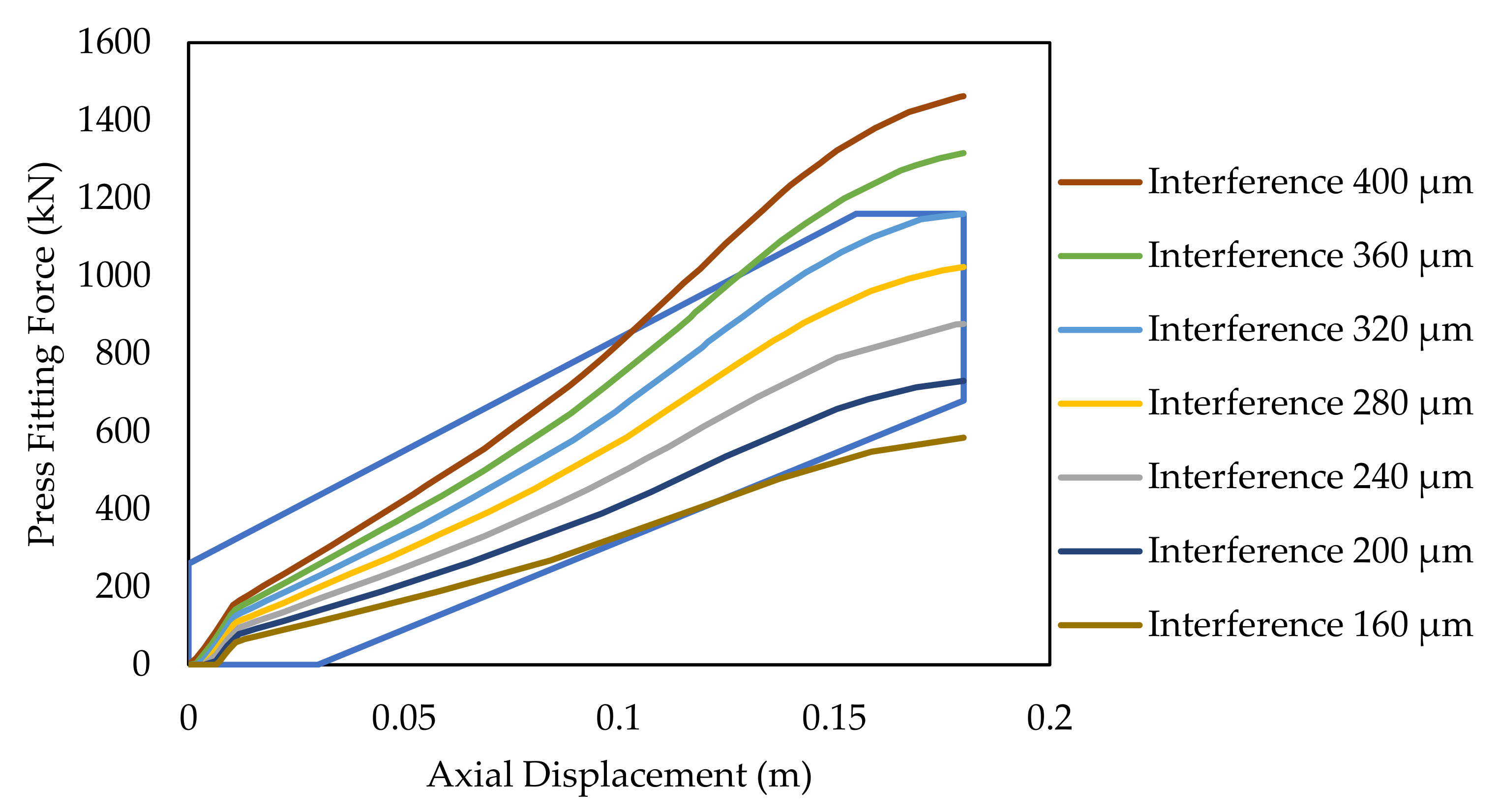
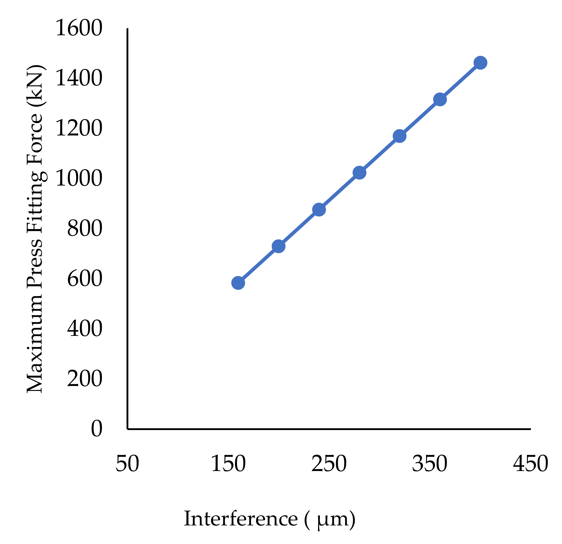
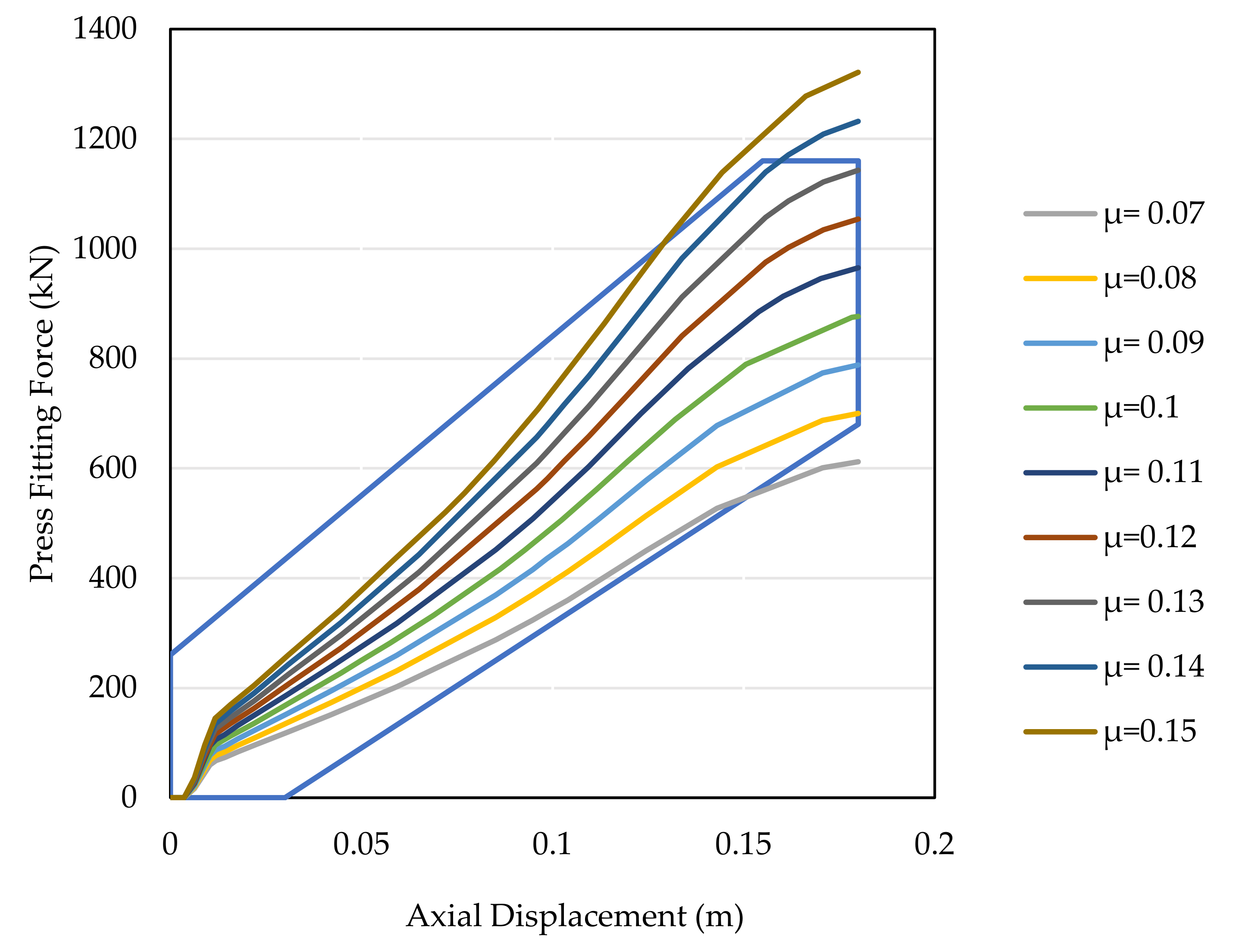
4.2. Effect of the Interference and Friction Coefficient on Press-Fitting Curves

The interference was a significant factor that affected the press-fitting curve. Simulations used interferences from 160 to 400 µm. The curves are shown in Figure 10. The press-fitting force increased, as expected, with the interference. The boundary of the press-fitting curve was obtained from the EN 13260 standard. The press-fitting curves were used for monitoring the assembly and evaluating its quality. The curves for interferences of 160, 360, and 400 µm did not qualify because they were outside the EN 13260 boundary. One key conclusion from the simulations was that the interferences, specified by the EN standard, fell within the boundary. When the interference increased by 20%, the maximum press-fitting force increased by 12% (Figure 11). Figure 12 shows the press-fitting forces and axial displacements from various friction coefficients obtained from the simulations. Friction coefficients in the range 0.08–0.13 were the only ones acceptable, i.e., led to forces within the boundary shown in Figure 12. Thus, it may be observed that the friction coefficient affected the press-fitting force during the assembly. In general, the greater the friction coefficient, the greater the maximum press-fitting force. Every 0.01 increment in the friction coefficient increased the maximum press-fitting force by 14% (Figure 13).

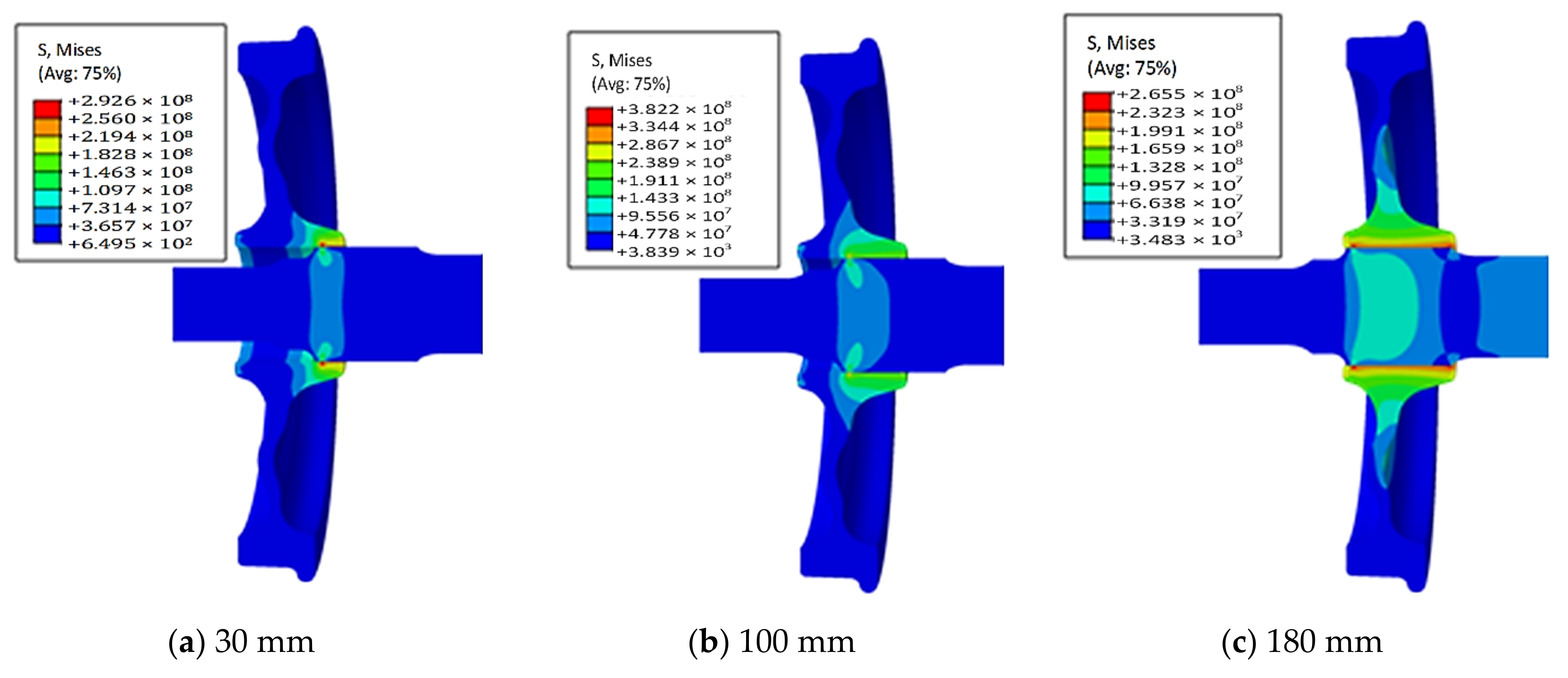
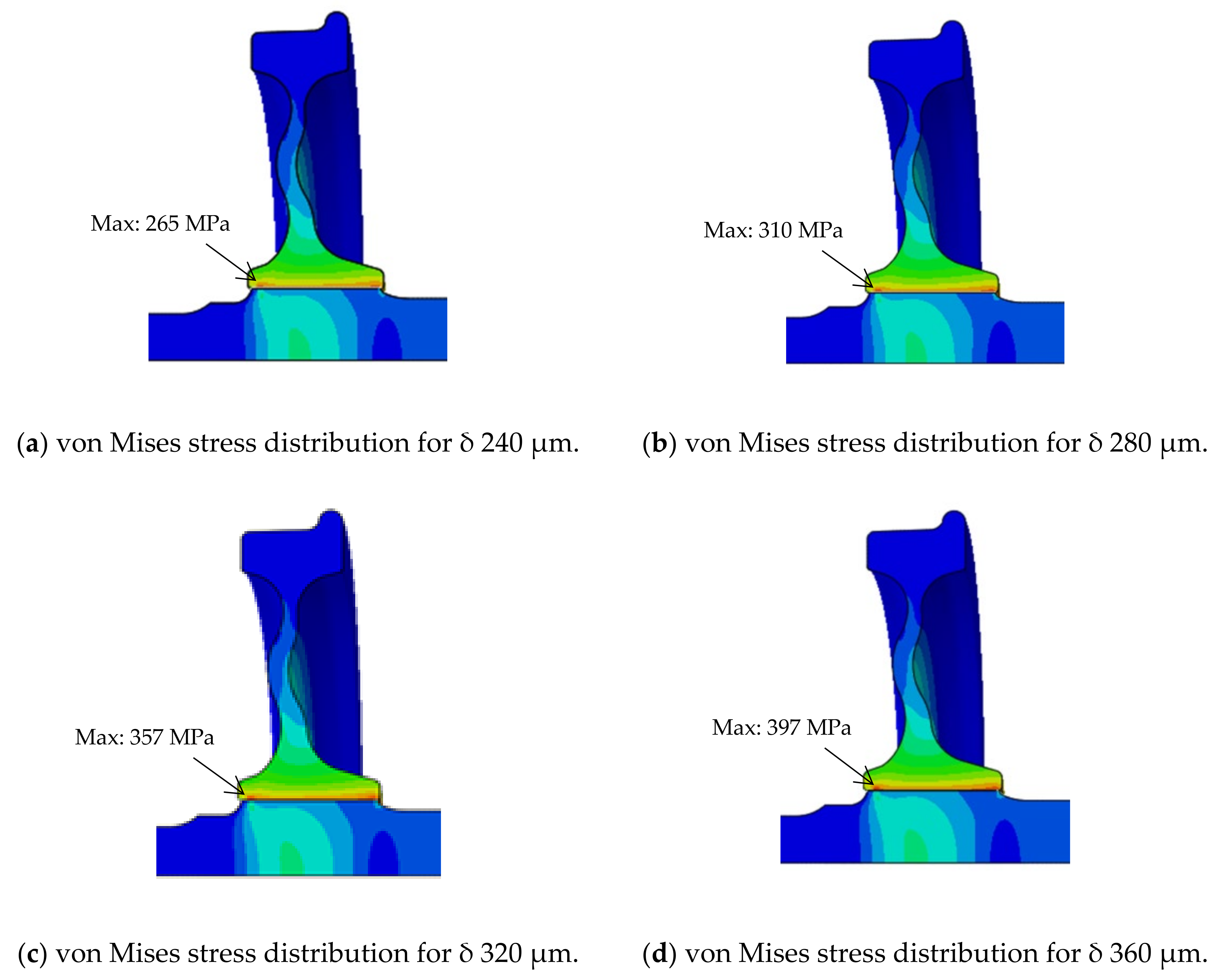
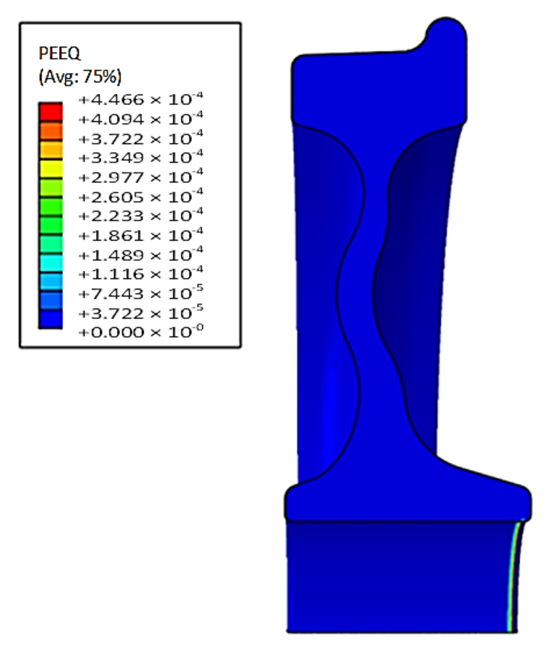
4.3. Contact Strength Analysis

The simulations showed that the maximum von Mises stress took place at the wheel, in contact with the axle wheel seat taper area, in the first simulation time step. The changing of the value and location of the maximum von Mises stress versus the axial displacement and time increment is shown in Figure 14. The von Mises stress was distributed symmetrically on both sides of the wheelset; the maximum stress occurred at the wheel hub bore after assembly. For the axle, the peak stress occurred at the start of the axle wheel seat at the end of the taper area. The maximum stress concentration was localized at the edge of the wheel hub because pressing the wheel to the axle induced critical stress due to the edge effect and abrupt transition in press-fitting. It can be minimized by some geometric characteristics, friction coefficient, contact pressure, and operation conditions. The maximum von Mises stress of the wheelset as a function of interference is shown in Figure 15. The simulations revealed that the interference value significantly affected the stress concentration.
To understand the effect of the interference on the deformation, note that for low values of the interference, up to 360 µm, deformations in the assembly remained in the elastic range. However, for sufficiently large interferences, 380 µm or more, elastoplastic deformation occurred in the wheel. Elastic plastic deformation began at the edge of the wheel hub bore first (Figure 16).

5. Effect of the Interference on the Holding Torque Capacity

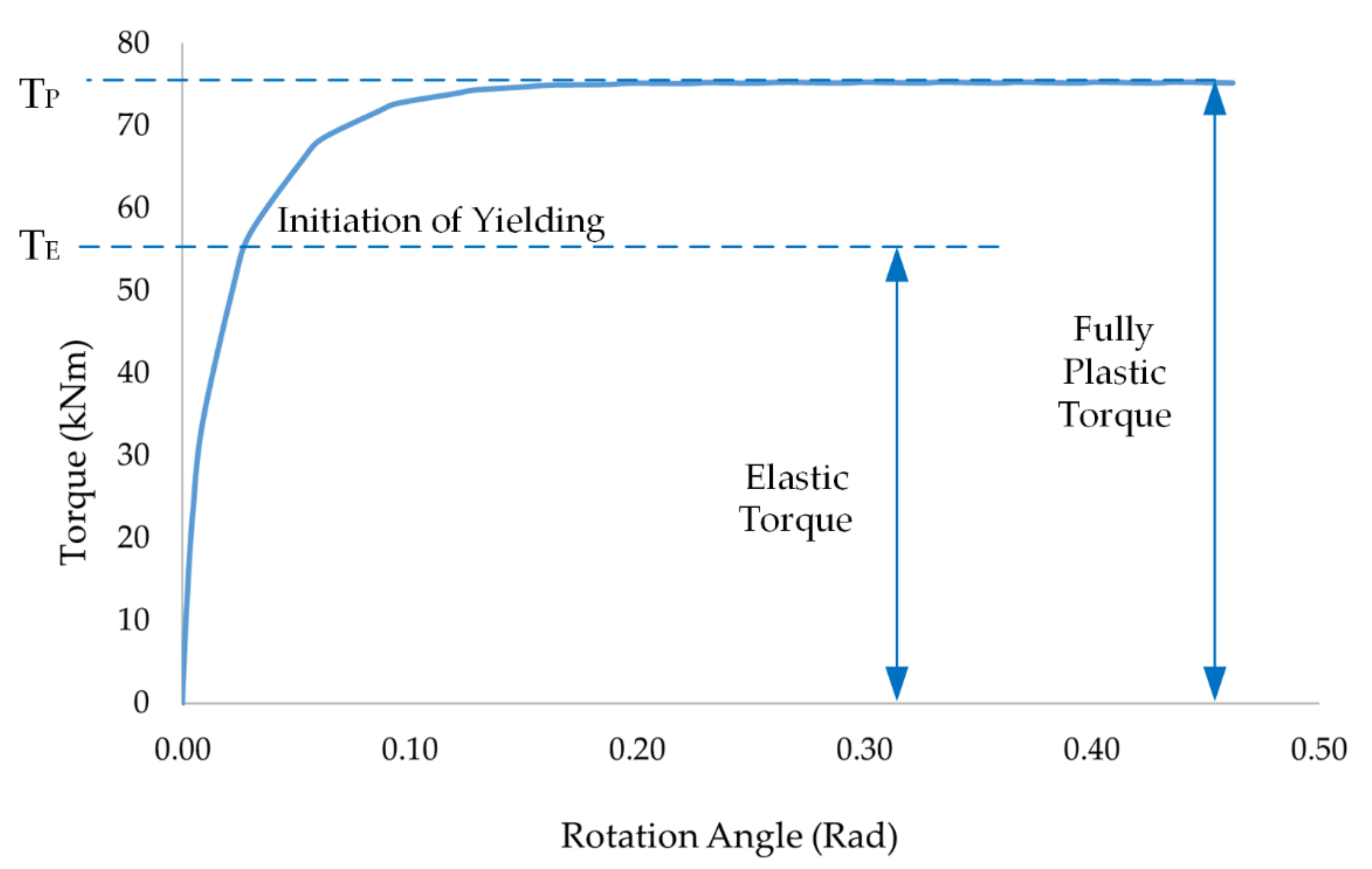
5.1. Maximum Holding Torque Capacity Theoretical Analysis

Railway wheelsets are generally running under many loading conditions, for example, vertical statics forces of the vehicle, wheel and rail contact forces in longitudinal, vertical, and lateral directions, inertial forces, etc. In operation, the contact force, especially in the longitudinal direction, significantly increases as the train is accelerated (traction) or decelerated (braking). This leads to a torsional moment on the wheelset, which may cause slippage at the wheel hub and axle seat. The maximum holding torque capacity, T, is the torque required to predict the slip between the wheel and the axle, as it resists the motion of the wheelset at the contact surface. It is transmitted by frictional forces on the wheelset and can be evaluated using Lame’s equation. It was assumed that the contact pressure in the assembly was uniformly distributed. The radial interference was significant for the holding torque capacity since it was related to the contact pressure and frictional force. The holding torque capacity of the wheelset, T, was thus a function of the frictional coefficient, contact area, and contact pressure [21]
T = μ D 2 A P d A
where μ is the static coefficient of friction, D is the axle diameter, P is the contact surface pressure, and A is the contact surface area. The holding torque capacity derived from Equation (5) was related to the contact length of the press-fit assembly (Figure 17). The maximum holding torque capacities were 71 kNm for the interference of 200 μm, 85 kNm for 240 μm, 99 kNm for 280 μm, and 113 kNm for 320 µm. Clearly, the holding torque capacity increased with the interference.

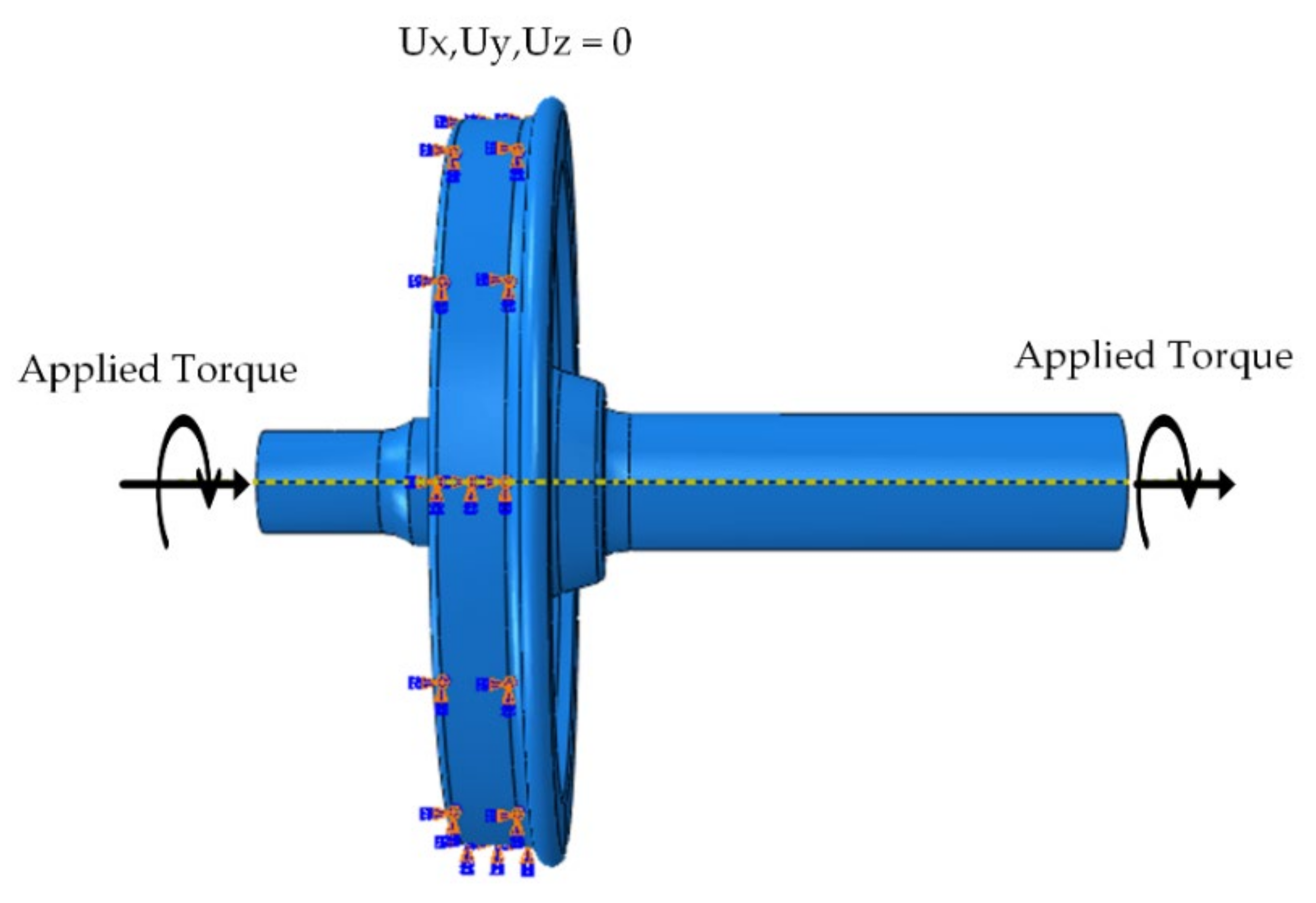
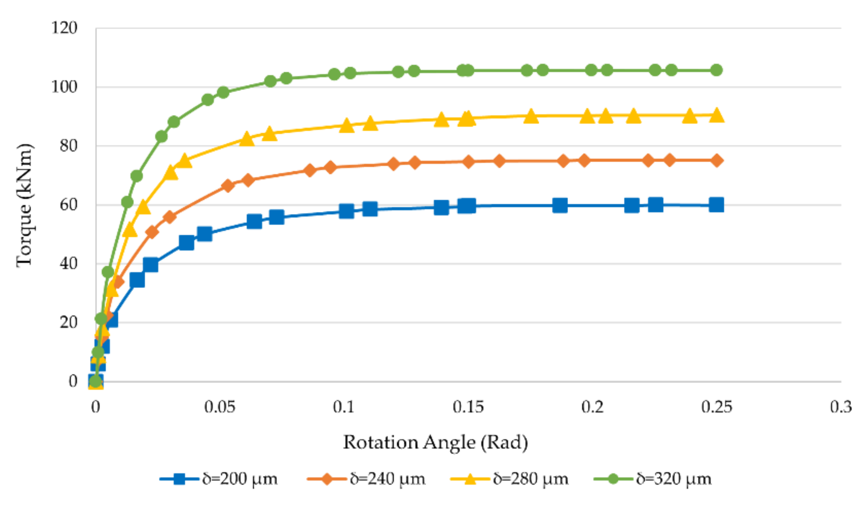
5.2. Finite Element Analysis of the Holding Torque Capacity

Finite element analysis was used to examine the effect of the interference on the holding torque capacity for the wheel and axle assembly. The geometry of the 3D models and materials properties were similar to those for the press-fitting finite element analysis. During this analysis, surface-to-surface contact interaction was set between the wheel and axle interface with a contact interference fit option. A penalty frictional coefficient, 0.1, and hard contact were set as the contact properties. It was necessary to define the reference points on the axle at both end sides of the centre point and coupling to the surface that defined the coupling nodes. To obtain more accurate results, a refined mesh was used at the contact area with a coarse mesh for the other areas. The torque loading was applied to the reference node at the end of the axle, and the outer surface of the wheel was fixed (Figure 18). The value of the applied torque was increased until rotation or ‘slip’ occurred in the interface.
The torque capacity analysis simulated the wheel and axle assemblies to obtain the curves of the torque and rotational angle, which determined the maximum holding torque capacity for different interference values. The torque and rotational angle curves were needed to decide the torque required to resist the slip between the interference assemblies. In Figure 19, TE was the maximum elastic torque, and yielding started at that point. Within the elastic torque region, the shear stress in the axle varied linearly, and the axle showed only elastic deformation. When the torque increased to the plastic region, Tp, the axle rotated continuously with no further increase in the torque. The maximum elastic torque was equal to 75% of the maximum holding torque capacity at the fully plastic region [22,23]. Therefore, it was evident that the maximum holding torque capacity or plastic torque, TP, before slipping was 75 kNm at the twist angle 0.15 rad, and the maximum elastic torque TE was 56 kNm at the twist angle 0.029 rad for the interference of 240 µm. TE did not exceed the 75% of TP for 240 µm, and others were also less than 75% of the maximum holding torque capacity. When the torque increased beyond the maximum holding torque capacity, the axle started slipping. The curves for the torque capacity simulated with different interferences are shown in Figure 20. Table 3 compares the maximum holding torque capacity with theoretical and finite element results. The deviations between the estimated maximum holding torque capacities from the theory and finite element analyses were 15% for 200 μm interference, 12% for 240 μm, 8% for 280 μm, and 6% for 320 μm. Thus, the finite element results agreed with the theory.

6. Conclusions

Finite element methods and the EN 13260 standard to generate press-fitting curves would provide engineers with valuable information to quickly identify press-fit quality. The authors of this study verified the press-fitting curves and maximum press-fitting forces obtained from finite element analysis by comparing them with the analytical results. To determine whether the press-fitting curve and maximum press-fitting force were acceptable, the EN 13260 standard was used. From the simulations, the press-fitting curves for assembling the wheel to the axle using the EN 13260 standard criteria were fully satisfied only when the interference ranged from 200 µm to 320 µm and the friction coefficient ranged from 0.08 to 0.13. The difference in the average contact pressure between the finite element and theoretical analyses was 3%. The maximum stress was found at a wheel hub inner surface due to the taper of the axle. The greater the interference, the greater the stress, which was due to the contact force. For interference of less than 360 µm, plastic deformation did not occur, and the EN standard limitation of the interferences for the wheelset could be used in the press-fitting. Furthermore, the maximum holding torque capacity positively correlated to the interference in the elastic range. In the plastic region, the torque is constant even though the twist angle increases. The deviation in the maximum holding torque capacity between the finite element analysis and theory ranged from 15% to 6% for different interferences. Since the maximum elastic torque did not exceed 75% of the maximum holding torque capacity, interferences from 200 to 320 μm were satisfactory. In summary, EN 13260 was very effective and can be used to assess the press-fit quality of the wheelset faster. The holding torque capacity formula (Equation 5) can be used to predict the maximum torque. In a future study, the authors will add experiments to verify the press-fitting curve.

Author Contributions

Conceptualization, T.N. and M.P.; methodology, T.N. and M.P.; software, T.N. and M.P.; validation, T.N. and M.P.; investigation, T.N.; resources, T.N.; writing—original draft preparation, T.N.; writing—review and editing, M.P.; visualization, T.N.; supervision, M.P.; project administration, M.P.; funding acquisition, M.P. All authors have read and agreed to the published version of the manuscript.

Funding

This research was funded by King Mongkut’s Institute of Technology Ladkrabang (Grant No. KDS2019/019).

Institutional Review Board Statement

Not applicable.

Informed Consent Statement

Not applicable.

Data Availability Statement

Not applicable.

Acknowledgments

This work was supported by King Mongkut’s Institute of Technology Ladkrabang.

Conflicts of Interest

The authors declare no conflict of interest.

References

  1. Kowalski, S. Failure Analysis of the Elements of a Forced-in Joint Operating in Rotational Bending Conditions. Eng. Fail. Anal. 2020, 118, 104864. [Google Scholar] [CrossRef]
  2. Kowalski, S. Fretting Wear in Selected Elements of Rail Vehicles. Teh. Vjesn. 2018, 25, 481–486. [Google Scholar] [CrossRef]
  3. Japanese Industrial Standard (JIS); Japanese Standards Association (JSA). JIS E 4504:2015-Rolling Stock–Wheelsets–Quality Requirements; JSA: Tokyo, Japan, 2015. [Google Scholar]
  4. European Committee For Standardization. EN 13260:2009+A1:2010: Railway Applications–Wheelsets and Bogies–Wheelsets–Product Requirements; BSI: London, UK, 2010. [Google Scholar]
  5. ISO 1005-7:1982. Railway Rolling Stock Material; Part 7: Wheelsets for Tractive and Trailing Stock; Quality Requirements, 1st ed.; International Organization for Standardization: Geneva, Switzerland, 1982. [Google Scholar]
  6. AAR. Manual of Standards and Recommended Practices Section G-II Wheel and Axle Manual; Association of American Railroads: Washington, DC, USA, 2019. [Google Scholar]
  7. Benuzzi, D.; Donzella, G. Prediction of the Press-Fit Curve in the Assembly of a Railway Axle and Wheel. Proc. Inst. Mech. Eng. Part F J. Rail Rapid Transit 2004, 218, 51–65. [Google Scholar] [CrossRef]
  8. Lu, J.; Xiao, J.; Gao, D.J.; Zong, S.Y.; Li, Z. Research on Standard and Automatic Judgment of Press-Fit Curve of Locomotive Wheel-Set Based on AAR Standard. In IOP Conference Series: Materials Science and Engineering; IOP Publishing Ltd.: Bristol, UK, 2018; Volume 326. [Google Scholar] [CrossRef] [Green Version]
  9. Saad, S.; Magnier, V.; Dufrenoy, P.; Charkaluk, E.; Demilly, F. Numerical Chain of Forging Railway Axle Andwheel Press Fitting Operation. Lect. Notes Mech. Eng. 2015, 789, 115–127. [Google Scholar] [CrossRef]
  10. Stamenković, D.; Milošević, M.; Mijajlović, M.; Banić, M. Recommendations for the Estimation of the Strength of the Railway Wheel Set Press Fit Joint. Proc. Inst. Mech. Eng. Part F J. Rail Rapid Transit 2012, 226, 48–61. [Google Scholar] [CrossRef]
  11. Michnej, M.; Guzowski, S. Fretting Wear Simulation in a Clamped Joint Based on the Example of a Rail Vehicle Wheel Set. Wear 2019, 438, 102654. [Google Scholar] [CrossRef]
  12. Booker, J.D.; Truman, C.E. Strengthing And Weakening Mechanisms in Interference-Fitted Joints. In Proceedings of the IRF2020: 7th International Conference Integrity-Reliability-Failure, Funchal, Portugal, 6–10 September 2020; pp. 405–418. [Google Scholar]
  13. Zhao, J.; Wang, J.-X.X.; Yu, C.; Tang, S.-Q.Q.; Yao, J. Influence of Radial Interference on Torque Capacity of Shrink-Fit Camshaft. Adv. Mech. Eng. 2019, 11, 1–10. [Google Scholar] [CrossRef] [Green Version]
  14. Joannides, T.; Leggoe, J.; Sercombe, T.; Mcarthur, J. Effects of Surface Topography and Interference on the Mounting Curve of Railway Wheel-Set Press-Fit Assembly; CEED: Crawley, Australia, 2017; pp. 25–30. [Google Scholar]
  15. SIMULIA. Abaqus Analysis User’s Manual; Dassault Systèmes Simulia Corp.: Providence, RI, USA, 2010; Volume I–IV. [Google Scholar]
  16. European Committee for Standardization. BS EN 13261: 2020 Railway Applications–Wheelsets and Bogies–Axles–Product Requirements; BSI: London, UK, 2020. [Google Scholar]
  17. European Committee for Standardization. BS EN 13262: 2020 Railway Applications Wheelsets and Bogies–Wheels–Product Requirements; BSI: London, UK, 2020. [Google Scholar]
  18. Budynas, R.G.; Nisbett, J.K. Shingley’s Mechanical Engineering Design, 8th ed.; McGraw-Hill: New York, NY, USA, 2006. [Google Scholar] [CrossRef]
  19. Son, S.-W.; Jung, H.-S.; Kwon, T.-S.; Kim, J.-S. Fatigue Life Prediction of a Railway Hollow Axle with a Tapered Bore Surface. Eng. Fail. Anal. 2015, 58, 44–55. [Google Scholar] [CrossRef]
  20. Uni Rail. Wheelset Catalouge; UniRail Ltd.: Sofia, Bulgaria, 2003. [Google Scholar]
  21. Rothbart, H. Mechanical Design Handbook, 2nd ed.; McGraw-Hill Education: New York, NY, USA, 2006. [Google Scholar]
  22. Hibbeler, R.C. Mechanics of Materials, 8th ed.; Prentice Hall: Hoboken, NJ, USA, 2010. [Google Scholar]
  23. Beer, F.P.; Johnston, E.R.; DeWolf, J.T.; Mazurek, D.F. Mechanics of Materials, 6th ed.; McGraw-Hill: New York, NY, USA, 2012. [Google Scholar]
Figure 1. Assembly of an axle and a wheel.
Applsci 11 08862 g001
Figure 2. Simplified model of a wheelset for theoretical analysis [7].
Applsci 11 08862 g002
Figure 3. Press-fitting curve for a railway wheelset: force vs axial displacement [4].
Applsci 11 08862 g003
Figure 4. Stress–plastic strain curve for EA4T steel.
Applsci 11 08862 g004
Figure 5. Dimensions of the wheelset [20].
Applsci 11 08862 g005
Figure 6. Boundary conditions.
Applsci 11 08862 g006
Figure 7. Mesh used by the finite element model.
Applsci 11 08862 g007
Figure 8. Contact pressure distribution along the contact length.
Applsci 11 08862 g008
Figure 9. Press-fitting curves obtained from the finite element model (FEM) and Lame’s theory (straight green line).
Applsci 11 08862 g009
Figure 10. Press-fitting curves vs interference derived from the finite element simulations.
Applsci 11 08862 g010
Figure 11. Maximum press-fitting force vs interference.
Applsci 11 08862 g011
Figure 12. Press-fitting curves with friction coefficient as a parameter.
Applsci 11 08862 g012
Figure 13. Maximum press-fitting force vs coefficient of friction.
Applsci 11 08862 g013
Figure 14. Von Mises stress distribution during simulation (a) axial displacement of 30 mm, (b) axial displacement of 100 mm, and (c) axial displacement of 180 mm.
Applsci 11 08862 g014
Figure 15. Von Mises stress of the wheel and axle due to radial interference (MPa).
Applsci 11 08862 g015
Figure 16. Equivalent plastic strain on the wheel.
Applsci 11 08862 g016
Figure 17. Holding torque capacity vs contact length.
Applsci 11 08862 g017
Figure 18. Loading and boundary conditions for the torque analysis.
Applsci 11 08862 g018
Figure 19. Torque vs. the rotation angle for 240 μm interference.
Applsci 11 08862 g019
Figure 20. Torque vs rotation angle for four interferences.
Applsci 11 08862 g020
Table 1. Chemical composition of EA4T steel [19].
GradeCMnSiSPCrCuNiMoV
EA4T0.290.80.40.0150.021.20.30.30.30.06
Table 2. Mechanical properties of EA4T steel [19].
MaterialYoung’s
Modulus (GPa)
Poisson
Ratio
Ultimate Tensile Strength (MPa)Yield Strength (MPa)Elongation (%)Absorbed Energy
EA4T2060.3650–800≥420≥24≥30
Table 3. Maximum holding torque capacity—theory and finite element versus interference.
Interference
(µm)
Maximum Holding Torque Capacity
Theory
(Equation (5)) (kNm)
Finite Element Method
(kNm)
Percent Deviation (%)
200716015
240857512
28099918
3201131066
Percent Deviation was calculated as
Percent Deviation = [(Theory-FEM)/Theory] × 100%
Publisher’s Note: MDPI stays neutral with regard to jurisdictional claims in published maps and institutional affiliations.

