Article

Autonomous Loading System for Load-Haul-Dump (LHD) Machines Used in Underground Mining

by
Carlos Tampier
,
Mauricio Mascaró
and
Javier Ruiz-del-Solar
*
Advanced Mining Technology Center, Department of Electrical Engineering, Universidad de Chile, Santiago 8370451, Chile
*
Author to whom correspondence should be addressed.
Appl. Sci. 2021, 11(18), 8718; https://doi.org/10.3390/app11188718
Submission received: 12 August 2021 / Revised: 3 September 2021 / Accepted: 3 September 2021 / Published: 18 September 2021
(This article belongs to the Special Issue Trends and Challenges in Robotic Applications)

Abstract

:
This paper describes an autonomous loading system for load-haul-dump (LHD) machines used in underground mining. The loading of fragmented rocks from draw points is a complex task due to many factors including: bucket-rock interaction forces that are difficult to model, humidity that increases cohesion forces, and the possible presence of boulders. The proposed system is designed to integrate all the relevant tasks required for ore loading: rock pile identification, LHD positioning in front of the ore pile, charging and excavating into the ore pile, pull back and payload weighing. The system follows the shared autonomy paradigm: given that the loading process may not be completed autonomously in some cases, it takes into account that the machine/agent can detect this situation and ask a human operator for assistance. The most novel component of the proposed autonomous loading system is the excavation algorithm, and the disclosure of the results obtained from its application in a real underground production environment. The excavation method is based on the way that human operators excavate: while excavating, the bucket is tilted intermittently in order to penetrate the material, and the boom of the LHD is lifted on demand to prevent or correct wheel skidding. Wheel skidding is detected with a patented method that uses LIDAR-based odometry and internal measurements of the LHD. While a complete loading system was designed, the validation had to be divided in two stages. One stage included the rock pile identification and positioning, and the other included the charging, excavation, pull back, and weighting processes. The stage concerning the excavation algorithm was validated using full-scale experiments with a real-size LHD in an underground copper mine in the north of Chile, while the stage concerning the rock pile identification was later validated using real data. The tests showed that the excavation algorithm is able to load the material with an average of 90% bucket fill factor using between three and four attempts (professional human operators required between two and three loading attempts in this mine).

1. Introduction

The automation of mining equipment is an important requirement in the mining industry. This is because mining operations need to increase the safety of the workers, as well as to augment the productivity, efficiency, and predictability of the processes. Safety is, without doubt, a key factor, and has been the top priority of mining companies during the past decades. This is particularly true for underground operations, with hazardous environments where workers are exposed to constant risks of rock falls, rock bursts, and mud rushes, and where the presence of dust in the air can result in a number of associated occupational diseases in workers [1]. All of these hazards have been steadily increasing as mine operations have gone deeper, and geomechanical conditions therefore become more extreme. As a consequence, great effort has been invested in increasing the automation level of underground mining machines, especially those that operate in high-risk areas [1], one of them being load-haul-dump (LHD) machines (also known as scoop trams).
An LHD is a four-wheeled, center-articulated vehicle with a frontal bucket used to load and transport ore on the production levels of an underground mine (see Figure 1). The automation of the transport phase has been covered in many previous publications [2,3,4,5,6] and is currently commercially available. However, although the loading part has also been a subject of scientific research, [7,8,9,10,11,12,13,14,15,16,17], its application in mining environments is not as widely used as other types of automation solutions such as autonomous navigation, assisted tele-operation, or collision avoidance. The slower-paced progress in this area could be due to the complexity of the addressed problem: during excavation, the interaction between the bucket and the material is difficult to model, because the bucket-material interaction forces may vary greatly depending on the properties of the material (e.g., humidity, hardness, fragmentation), the rock pile geometry, and the LHD dynamics (mass, speed, etc.). For this reason, the development of autonomous loading solutions requires full-scale experiments under conditions that can be found only in real mining environments, since physical interactions between the machine and the fragmented rock cannot be easily reproduced elsewhere. This adds to the fact that loading maneuvers and techniques are mostly developed and perfected through the experiences of human operators.
In this paper, a complete system for the automation of the loading process using LHDs is proposed. This system is designed to integrate all the relevant tasks required for ore loading: rock pile identification, the LHD’s positioning in front of the ore pile, charging, excavation, pull back, and payload weighing (see Figure 2). Assuming that in some cases the loading may not be completed autonomously, the system can detect this situation and request the help of a human operator (by tele-operation). Thus, the proposed system falls under the shared autonomy paradigm. In the mining exploitation context, fleets of LHDs are normally supervised by humans, so providing assistance to an autonomous equipment is not an unusual requirement, especially considering that the most common practice is for LHD automation systems to rely on tele-operators to handle the loading task. It must be noticed that providing assistance on demand, i.e., only in the few cases that the autonomous system is not able to load, is much more efficient than the current semi-autonomous operation used in most commercial systems, where navigation is executed autonomously but loading is teleoperated.
The core of the autonomous loading system is the excavation algorithm, which is based on the way that human operators excavate: the bucket is tilted intermittently while excavating in order to penetrate the material, and the boom of the LHD is lifted on demand to prevent or correct wheel skidding. Wheel skidding is detected with a patented method that uses LIDAR-based odometry and internal measurements of the LHD’s actuators [18]. The excavation algorithm was validated in an underground mine (a sublevel stoping copper mine located in Chile), using full-scale excavation experiments with a real LHD and a typical production rock pile. The validation process in a productive area of a real mine and the lessons learned are fully disclosed here. The 2D-pile modeling was validated afterwards with data from these tests.
It is also important to mention that commercial solutions to the problems of autonomous loading need to be compatible with the 24 × 7 operation of mines, where production throughput is one of the main requirements. That means that the LHD needs to be able to load without stopping during the transition from navigation to loading. The proposed automation framework considers this requirement, and it is able to characterize the rock pile, without stopping the LHD, while it approaches the pile.
The main contributions of this paper are:
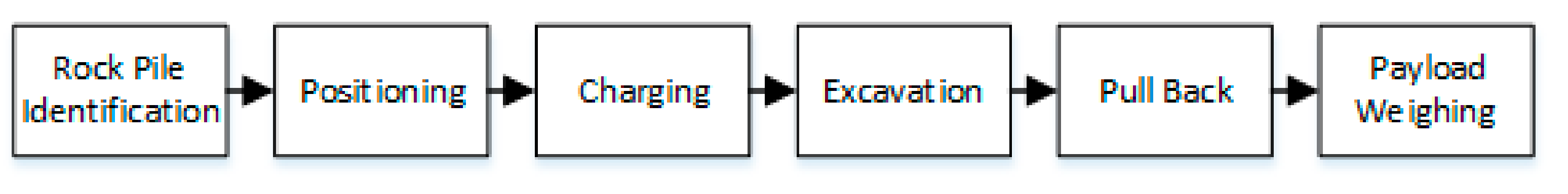
  • A system that models and implements the whole loading process required in underground mining operations, from rock pile identification to payload weighing. The system is based on the shared autonomy paradigm, which allows the system to obtain assistance on demand from a human operator.
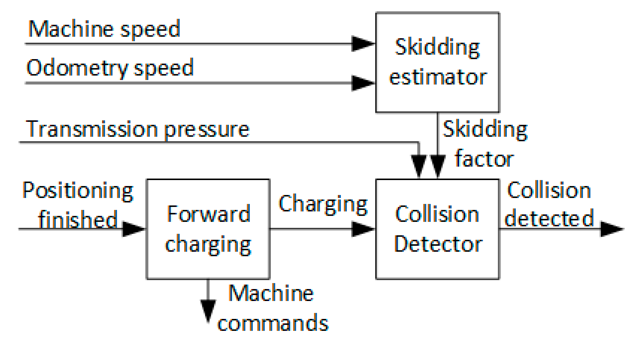
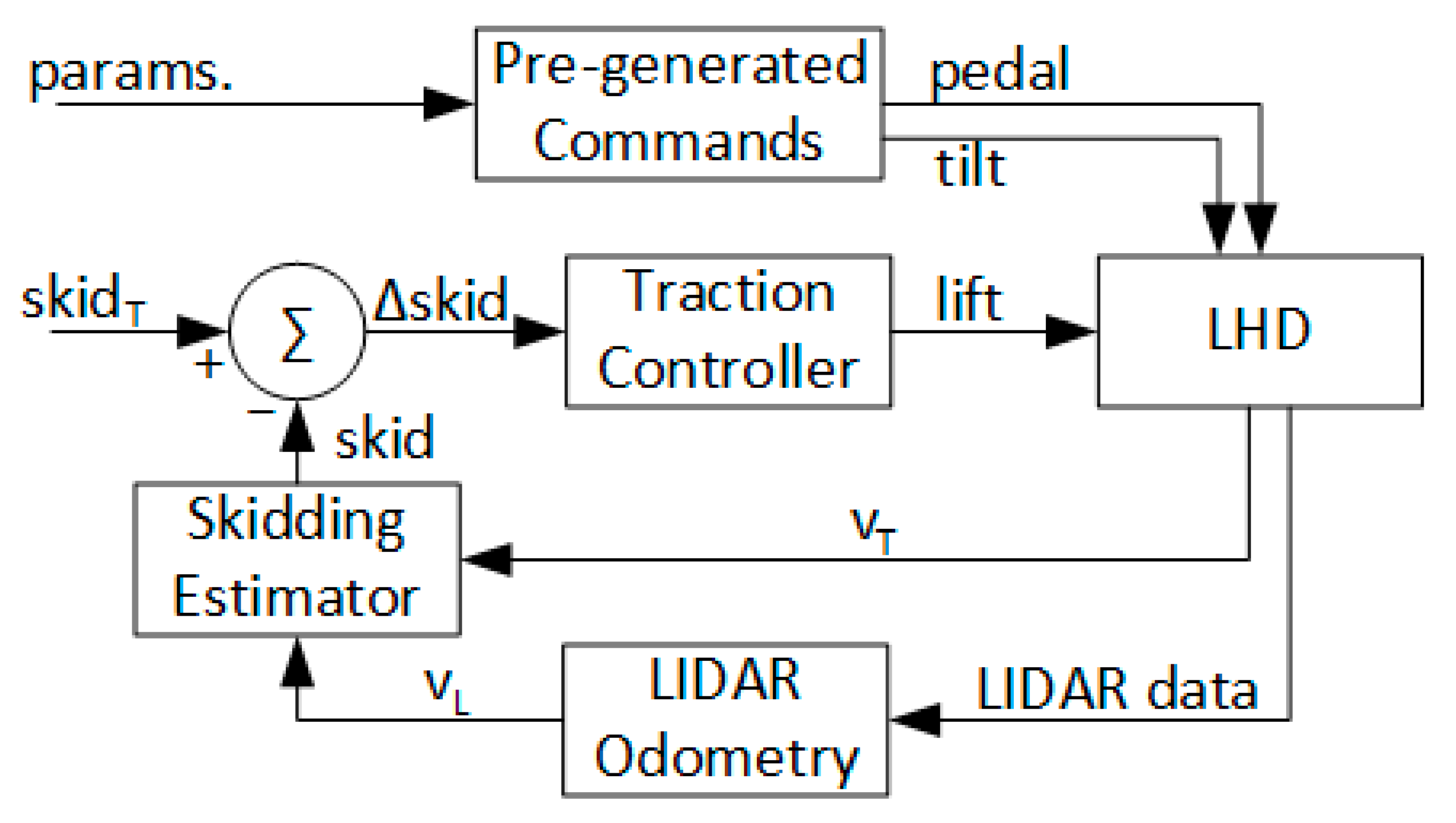
  • An excavation algorithm that is based on the way that human operators excavate, and that uses a patented method for detecting wheel skidding, which is required for successful excavation of fragmented material in draw points.
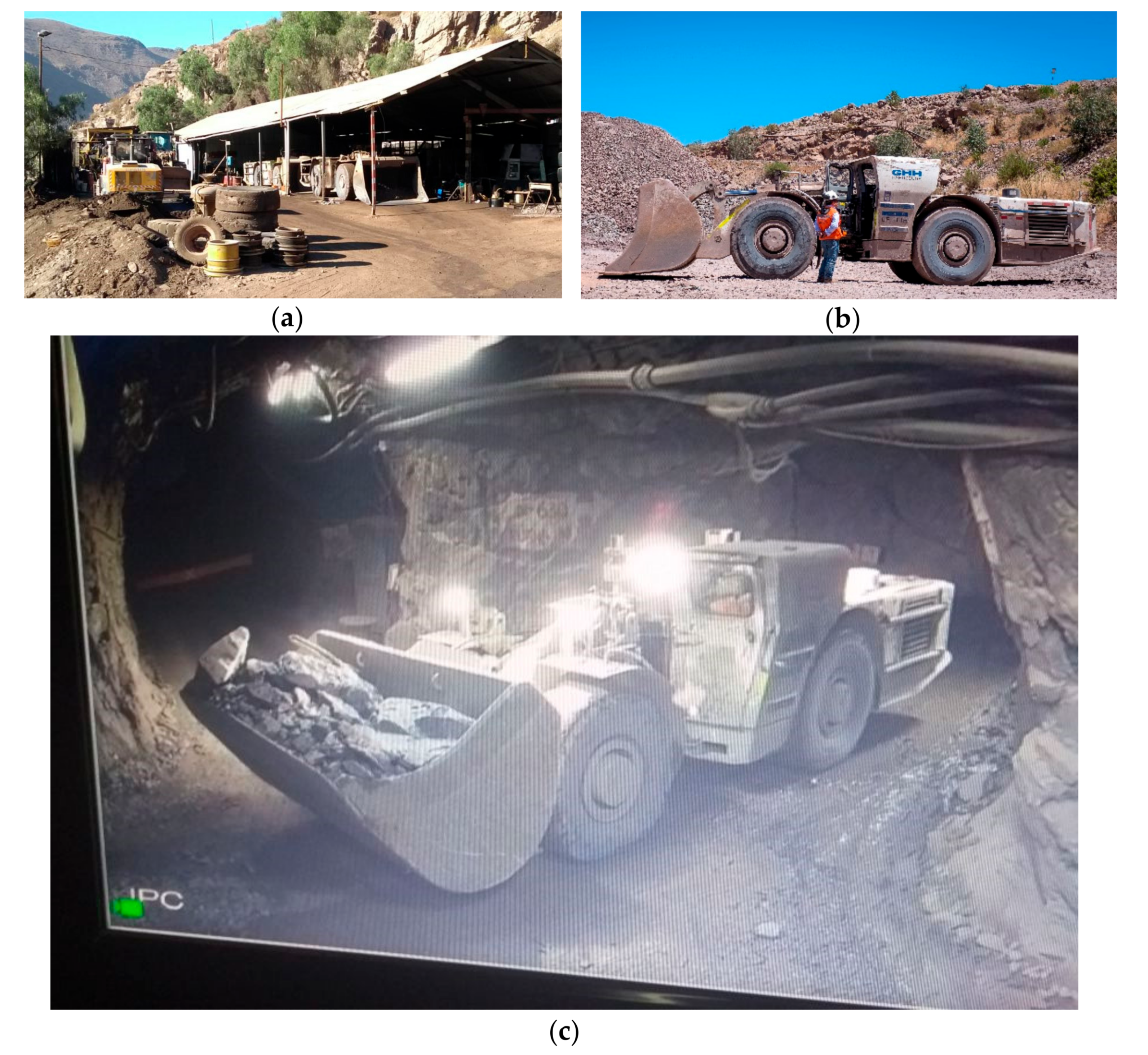
  • Full-scale rock excavation experiments using a commercial LHD in a production level of a sublevel stoping mine.
This paper is organized as follows: Section 2 presents the background and related work on loading automation for LHDs. Section 3 describes the proposed autonomous loading system. In Section 4, results of the full-scale experiments are shown and discussed. Finally, in Section 5, the main conclusions of this work are drawn.

2. Background and Related Work

2.1. Problem Description

Autonomous loading of fragmented rock involves a sequence of steps: As the LHD’s operator approaches the draw point, a swift assessment of the condition of the rock pile is made. The bucket of the LHD is tilted downwards until the tip is pressed against the ground. Next, the machine is commanded to charge at the rock pile. After the LHD makes contact, it buries the bucket in the rock pile, and bucket tilt and lift movements are issued as it advances through the fragmented rock. When sufficient penetration is achieved, the bucket is fully retracted, and the vehicle is withdrawn with a reverse motion. Then, the operator shakes the bucket briefly and assesses whether or not enough ore has been loaded. If necessary, a new loading maneuver is carried out.
The step in which the machine is being controlled to dig into the rock pile will herein be referred to as the excavation process. During excavation, bucket-rock interaction forces affect the bucket motion through the material, and ultimately define the amount of ore loaded. Granular material inter-particle forces, as well as bucket-rock interactions, have been studied previously, but their complexity has led only to stochastic modeling [19]. In consequence, an analytical approach to bucket motion control is not possible, and accurately replicating these interactions to develop a system in simulation is highly unlikely. Hence, only a real environment offers suitable conditions for development of, and experimentation with, an excavation procedure. Furthermore, fragmented rock, unlike piled sand or gravel, is much more difficult to load. This is aggravated due to the environmental conditions in underground mining. Depending on the mining method, the column of blasted rock might exert large compression forces on the open face of the draw point (see Figure 3). Humidity can also increase cohesion forces, making the overall process more difficult [20]. Moreover, large rocks can be present in the draw point. For this reason, the operator needs to detect the presence of large rocks while approaching the draw point, and, depending on their size, could be forced to change the goal of the maneuver from filling the bucket to just loading one large rock. If the rock is too big to be loaded, the task is aborted. Furthermore, other conditions, such as narrow tunnels, uneven or unprepared terrain, and/or significant amounts of water and mud near the draw point, can make the loading process very challenging. An autonomous system should be prepared to handle all these situations in addition to performing certain processing and steps that a human operator deals with while driving the LHD, such as detecting an accurate enough position of the rock pile before charging at it, making sure not to hit the tunnel while pulling back from the rock, and estimating if the bucket is full enough.

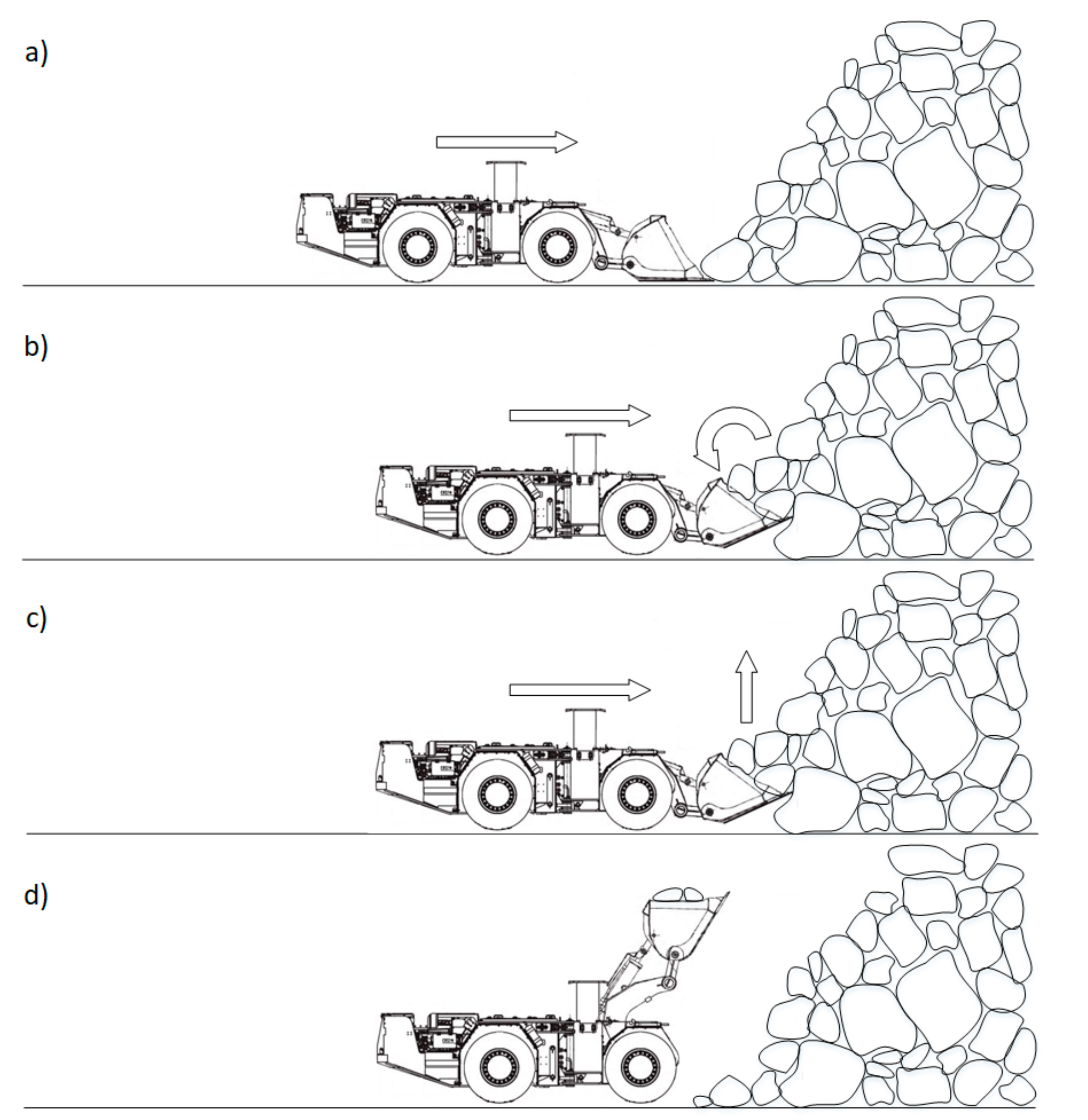
2.2. How Human Operators Excavate

The excavation process is the core of the loading maneuver; it is the crucial step and, since bucket-rock interactions cannot be predicted in advance, there is no optimal method for performing this operation. Nevertheless, human operators have had to deal with this situation by learning the loading technique from experience and shared good practices. It is natural, therefore, to analyze which ideas can be borrowed from them. Through several interviews with LHD operators of Chilean block caving and sublevel stoping mining companies, and discussions and analysis of data from mining operation manuals, some common points in their practices were identified:
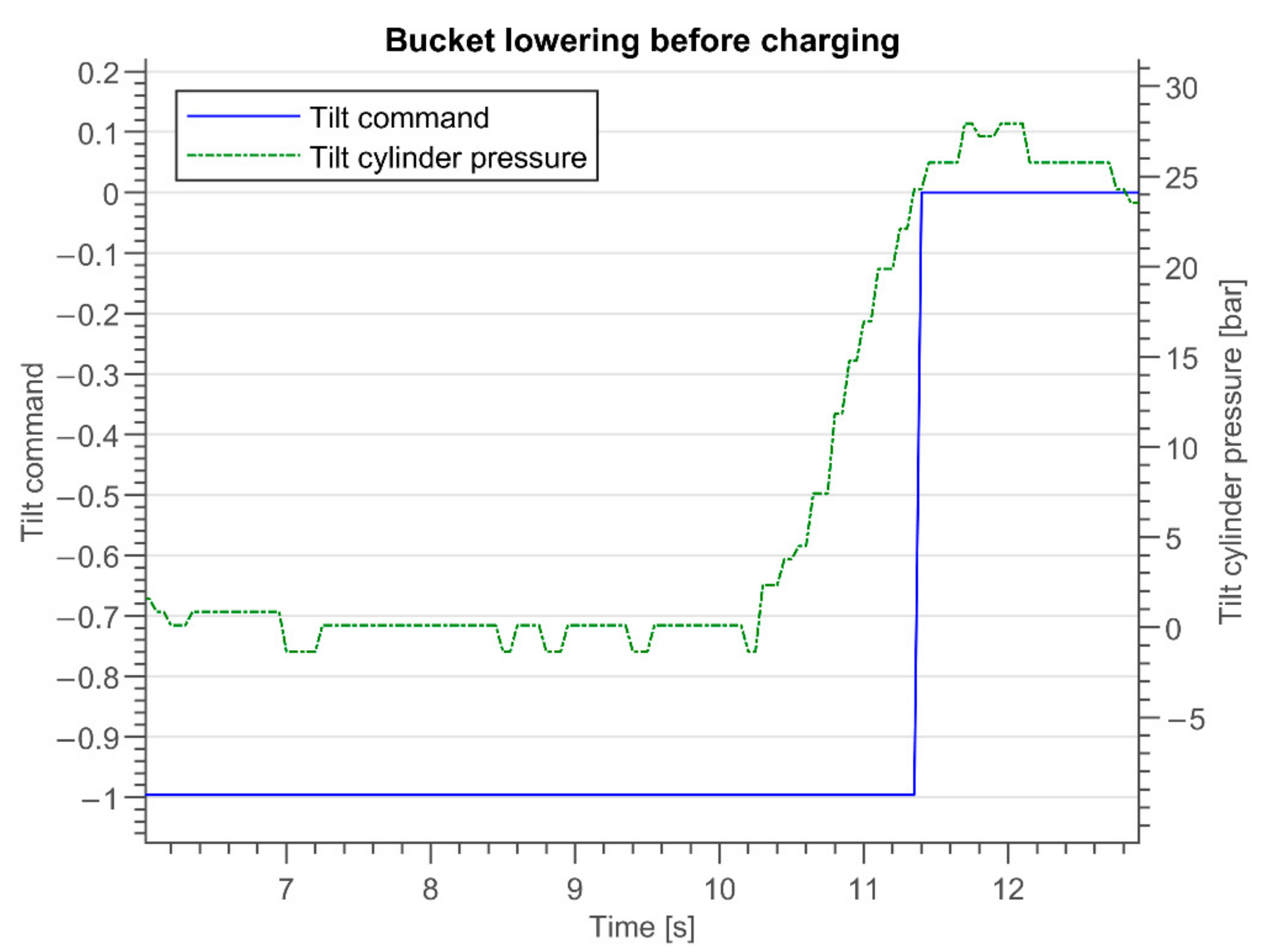
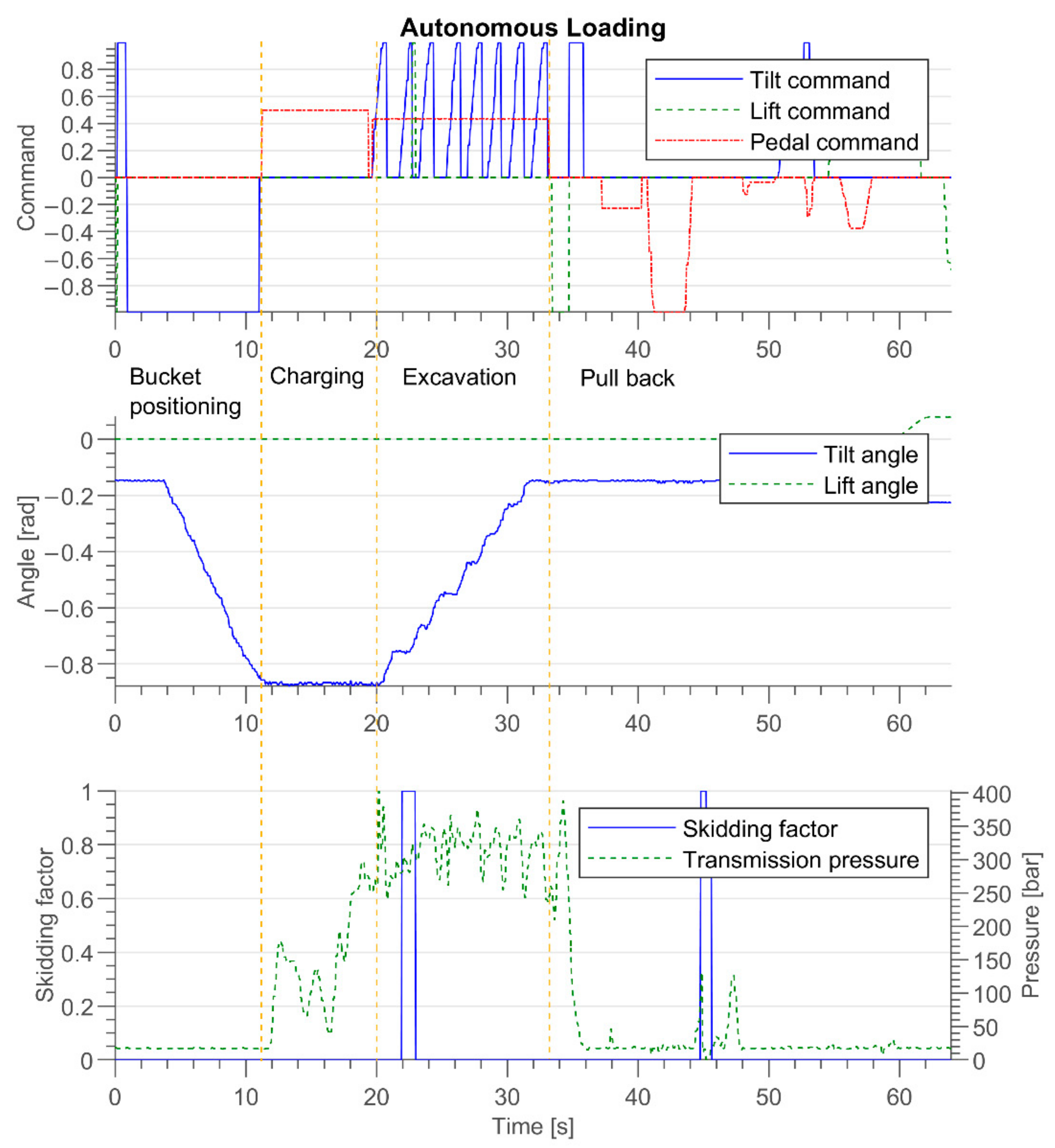
  • Before engaging with the rock pile, the bucket must be fully extended.
  • Forward motion is selected for maximum traction (first gear).
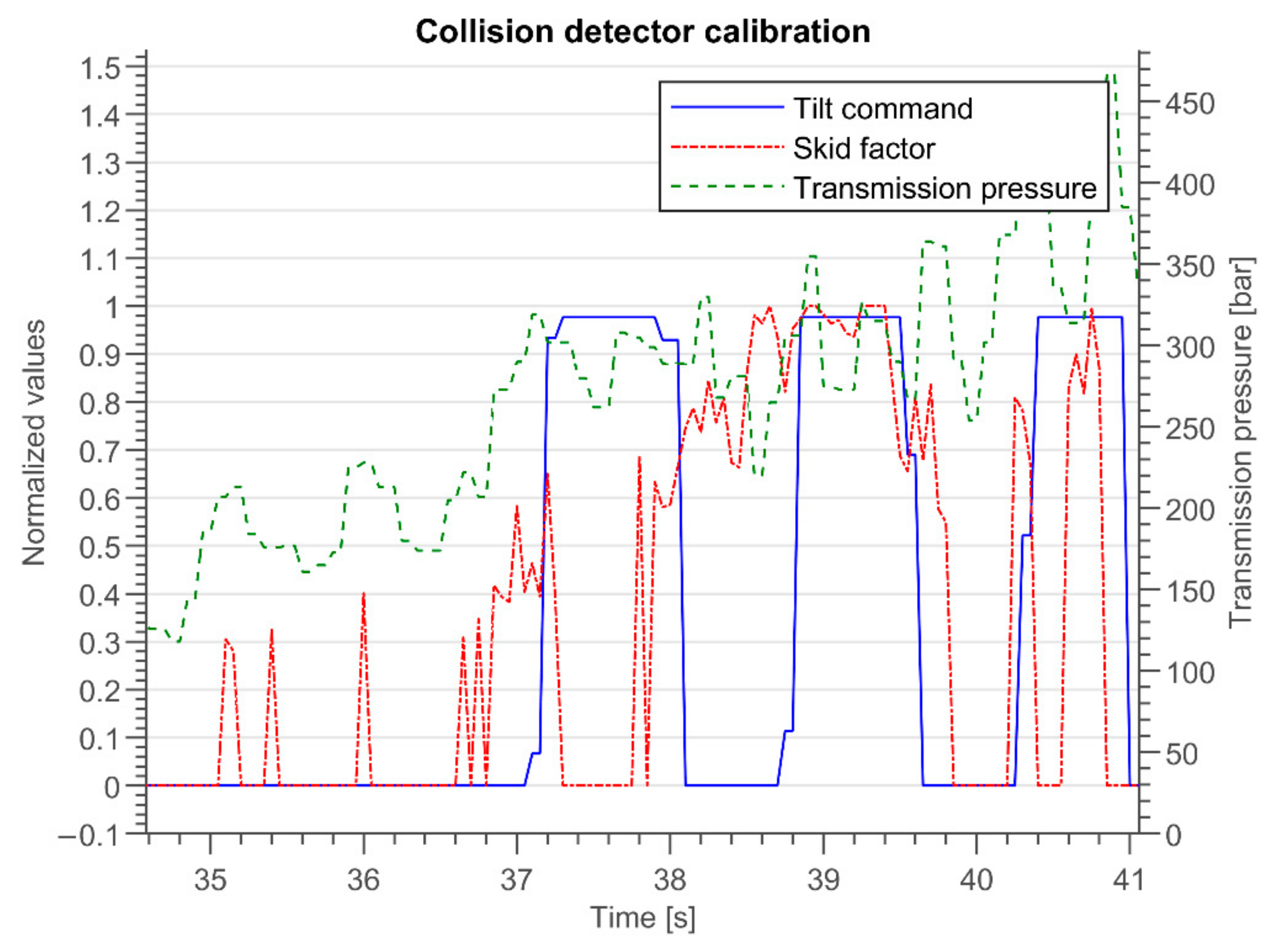
  • Intermittent tilt commands are the basis of the excavation process.
  • Lift commands are mainly issued to prevent or correct wheel skidding.
Figure 4 shows a graphical representation of an excavation maneuver. First, the LHD engages with the rock pile, then the bucket is tilted in order to excavate on the muck pile. When the wheels lose traction, the boom is lifted to regain traction. After filling the bucket, the LHD pulls back. Figure 5 shows a graphic of some of the relevant variables during a line-of-sight remote-controlled loading maneuver. As mentioned, bucket tilting (“tilt command”) is activated intermittently. Its duration and shape vary among operators and loading attempts. Techniques also using negative tilt commands (downwards tilting of the bucket) were also encountered in combination with positive lift commands (“lift command”). The common factor in all of them was the intermittency of the commands. As for the lift command, its use was seen to be highly variable, which correlates with the notion of using it mainly to prevent wheel skidding. In the example of Figure 5, the lift command was not used at all. The “pedal command” is the one used for machine acceleration and thus, in turn, engine revolutions per minute (RPM). “Tilt angle” and “lift angle” are the bucket tilt and boom lift angle values, estimated through the encoders installed in the machine. “Transmission pressure” is the hydrostatic transmission pressure of the machine, a variable that can be associated with the engine’s power output. “Skidding factor” is an estimated skidding factor that is explained in Section 3.3.

2.3. Related Work

Mikrived analyzed the interaction forces in excavation processes and proposed that measurements of the resistive forces could be used for controlling them [21]. Hemami studied the LHD loading process and dealt with theoretical formulations on bucket trajectory and resistive forces during a scooping motion [7,8,10]. Other work has addressed the loading problem using laboratory-scale prototypes, under less realistic conditions [9,11,12,22]. Research on autonomous loading showed scarce progress up until the past decade. In [13], full-scale experiments with a real LHD were performed using a proposed admittance-based controller for bucket commands. This work was further extended in [15,16,17] with support from the LHD original equipment manufacturer (OEM) Atlas Copco (now Epiroc), a study that led to a patented method [23]. It should be noted that this method addresses only the problem of ore excavating once the bucket is inside the rock pile. On the other hand, our approach comprehends the complete loading process, while also benefiting from human experience.
Caterpillar, another LHD OEM, is known to have been working on technical solutions for the autonomous loading problem, as demonstrated by patents [24,25,26]. While their patents show that they have tackled different issues of the autonomous loading problem, a general system has not been described, and their research has not been made available to the scientific community. However, it is uncertain if either of these solutions are able to handle the loading problem in block/panel caving draw points, which is significantly harder than loading from an ore pile or from draw points originated by other mining methods. As mentioned, loading from draw points is difficult due to many factors including: bucket-rock interaction forces that are difficult to model, humidity that increases cohesion forces, and the possible presence of boulders.
According to the public information shared on the web sites of LHD OEMs, only Epiroc, Sandvik, and RCT Global have commercially available products that focus on the autonomous loading task. However, specific features, limitations, and applicability for block/panel caving or sublevel stoping underground mining are not publicly disclosed, and therefore no comments can be made on them. At least in Chile, where all major mining companies operate and where one third of the world’s copper is produced, no autonomous loading system for LHD is in use.
Work associated with standard front-end loaders was not considered in this analysis, because they operate on the surface, where the difficulties associated with underground draw points are not present. In addition, these types of vehicles usually deal with material that has already been processed by milling equipment.
Our previous work on the topic of autonomous loading with LHDs was focused on laboratory-scale trials [27]. While useful for an initial approach to an experimental setup, laboratory experiments are limited due to the large deviation between real-world operating conditions and data from a small-scale and controlled environment. Other laboratory work is presented by Shi [22], which has some similarities with the here-presented method, as excavation is modeled after the experience of human operators. However, since their experiments are carried out using a robotic arm, it is difficult to apply those findings to a four-wheeled machine such as an LHD.
As can be seen, little work has been published on the particular case of autonomous loading with LHD machines in real underground mining environments, and, as far as we know, no previous method has validated an excavation technique using human operator experiential knowledge under real underground mining conditions.

3. Proposed Autonomous Loading System

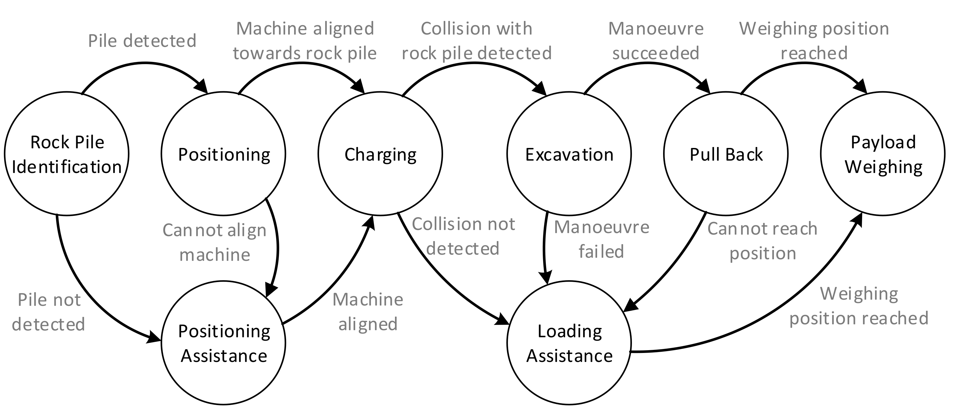
3.1. Methodology Overview

The hardware used in this work included a full-scale LHD machine (a GHH LF11H with 11-ton tramming capacity and hydraulic powertrain) retrofitted with two 2D laser scanners (SICK LMS511), encoders in all joints (IFM RN7012), pressure sensors along the bucket’s tilt and the boom’s lift hydraulic lines (manufacturer specific, 600 bar), and an onboard industrial computer (Advantech ARK-2151-59AIE) (see Figure 1). All components are of industrial grade, suitable for the rigorous environment of underground mining, and readily available as off-the-shelf components used widely in a broad range of commercial applications. In order to better integrate the system with commercial autonomous navigation solutions for LHDs, which only use 2D scanners, 3D laser scanners were not used in the current version of the proposed system. The software implementation was performed using ROS as the central middleware [28], CABSL library [29] for state-machine codification, and ROS actions to interface with the main processing function in each state. The system was initially developed and tested in a simulated environment using Gazebo [30].
An autonomous loading routine can be thought of as a sequence of several steps that perform specific actions, as presented in the diagram of Figure 2. There, rock pile identification is the process of finding the draw point’s location and status (whether it is suited for loading or not). Positioning refers to orienting the LHD machine to ensure that a forward thrust will end in a collision with the rock pile. Charging is the step that considers lowering the bucket and accelerating towards the pile. Excavation is the machine control that performs the digging action. Pull back comprises the backward motion of the vehicle and bucket shake. Finally, Payload weighing estimates the amount of ore loaded. Most of the mentioned steps could fail due to the highly variable environment in underground mining. It is possible that the onboard sensors fail to find the rock pile accurately or that the machine positioning cannot avoid colliding with a tunnel wall. The collision between the machine and the rock pile might not be detected, and the LHD’s bucket could become stuck during excavation. In any of these cases, human assistance would be required to overcome the problematic situation. In fact, human interaction with automated mobile machines for mining operations is needed in the state-of-the-art systems, at the very least to supervise a fleet of machines. Since large-scale operations have a fleet of vehicles, it is common for one or more operators to supervise and assist multiple semi-autonomous machinery, as each machine does not require constant attention. For these reasons, in our view, it is imperative that this human interaction is considered at the design stage of the autonomous loading system and, thus, included in the formulation of the agent’s behavior. Figure 6 shows the proposed state machine for the autonomous loading process with the human in the loop. There are two assistance states: positioning assistance allows the operator to take control of the machine to position it in front of the rock pile, while loading assistance provides the operator with full control of the LHD to perform the remaining parts of the loading maneuver up until payload weighing, which is needed to record the performance of the task. The positioning assistance is called either when the rock pile identification cannot characterize the rock or when positioning is not able to place the LHD to start the charging procedure, while loading assistance is called when the charging, the excavation, or the pull back procedures cannot be successfully completed.

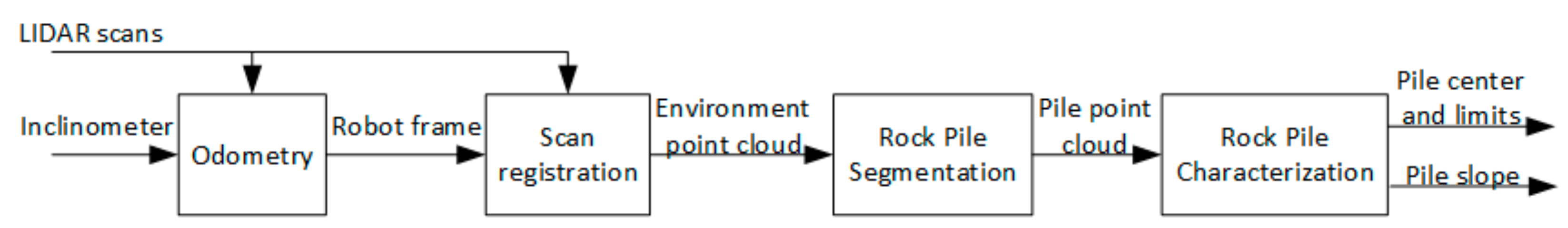
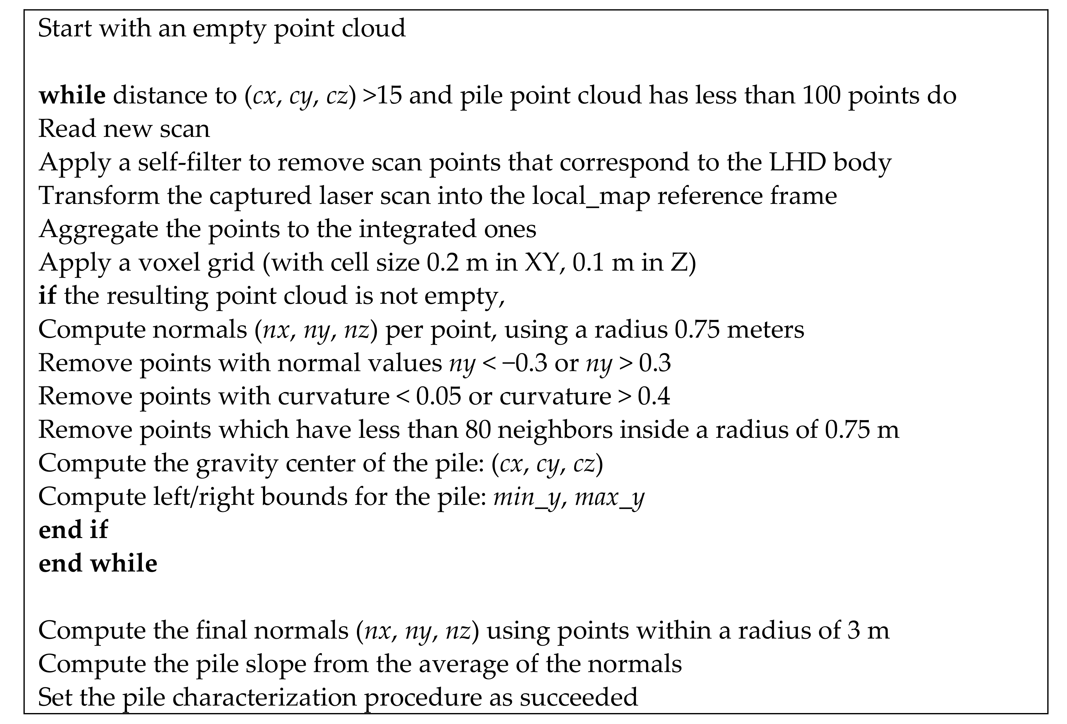
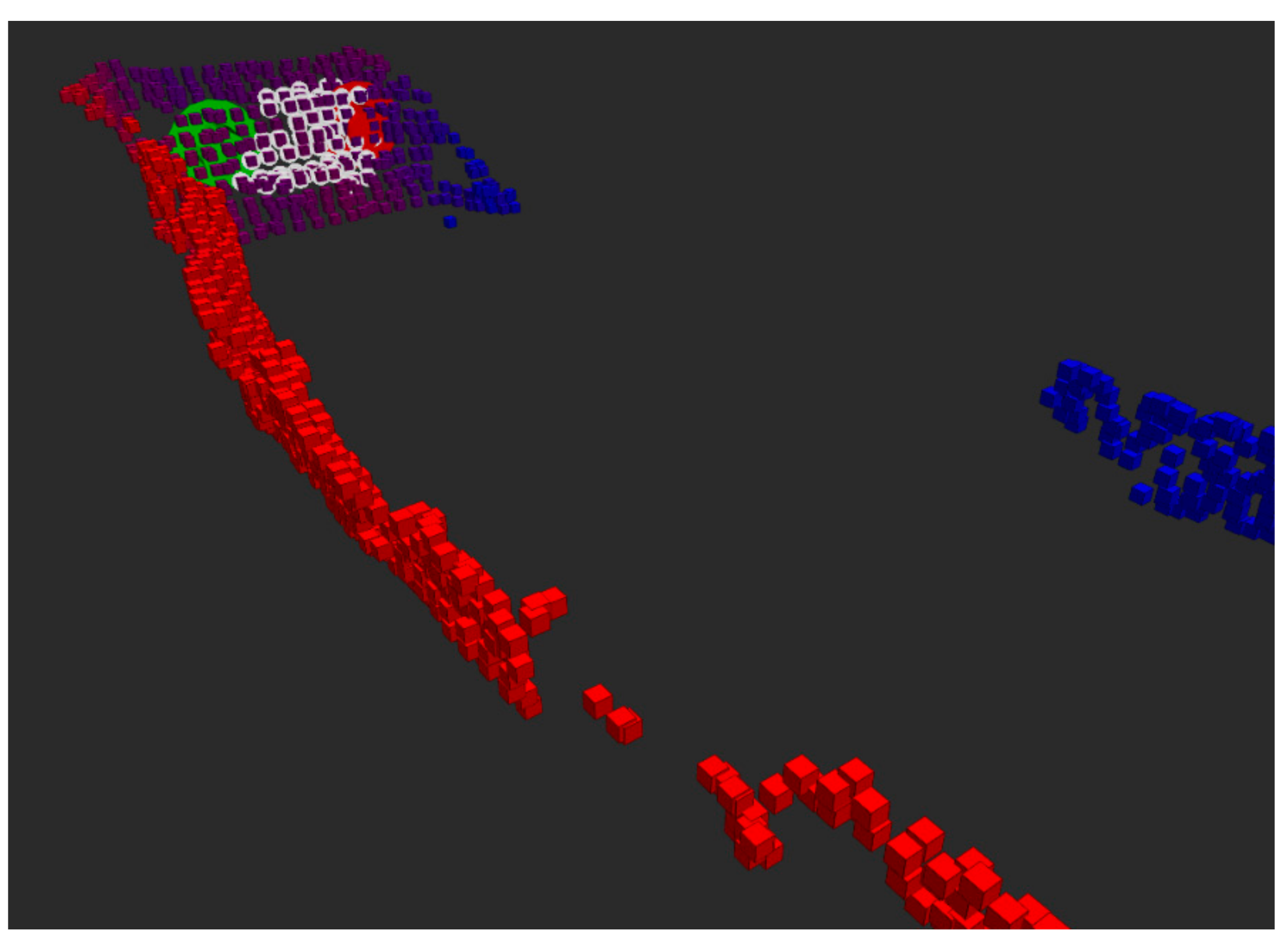
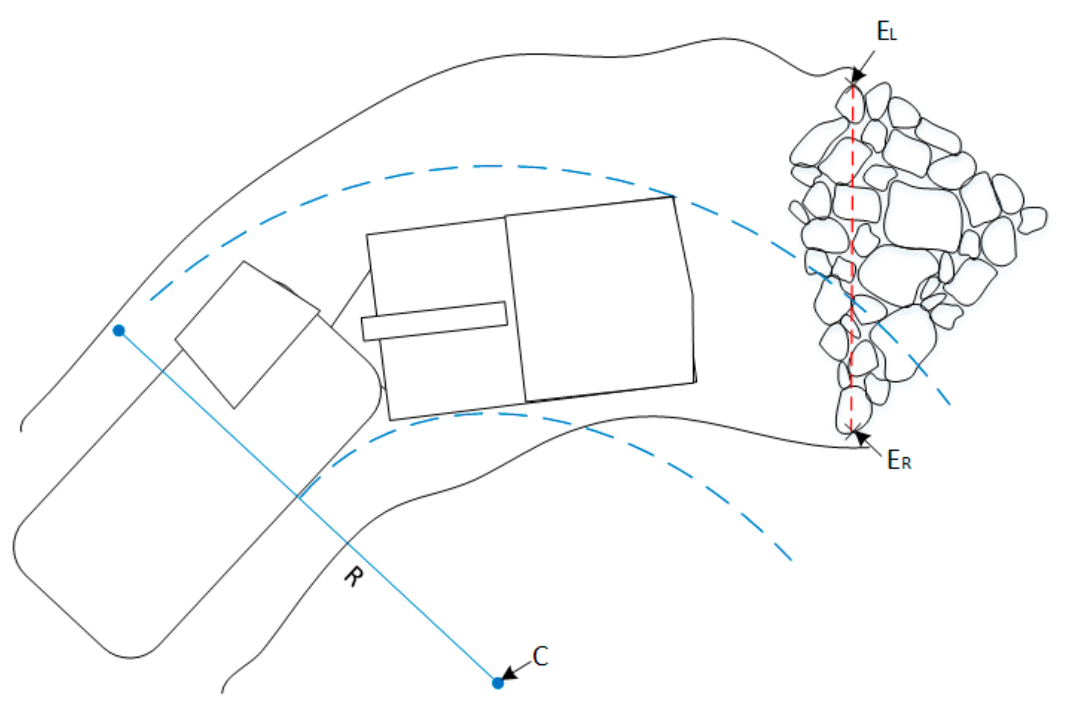
3.2. Environment Modeling and Rock Pile Identification

Of the six steps of the autonomous loading routine, the first one, rock pile identification, is the one that most strongly relies on the processing of data acquired from the environment. The aim of this step is to find the location and status of the draw point accurately, in real time, and without the need of extra steps or delays. This means that the LHD is required to continue moving while scanning the pile. The characterization of the rock pile is performed through integration of consecutive laser scans from the frontal 2D LIDAR sensor mounted on the LHD. The integration of the laser scans relies on a LIDAR-based odometry method [31], and the output of the machine’s inclinometer data, which is filtered and integrated in the local coordinate frame in order to benefit from the natural tilting of the LHD while moving across uneven terrain. The aforementioned odometry method consists of an adaptive frame rate modification of the range-flow based odometry (RF2O) [32]. While RF2O computes displacement by comparing two scans, using the “range flow constraint equation”, the adaptive frame rate implements a control over the processing frequency, increasing it at higher machine speeds.
A block diagram for the pile identification step is presented in Figure 7. The LIDAR odometry enables the integration of 2D laser scans into a 3D point cloud of the environment. Then, the rock pile is segmented, and its features are computed (center, limits, and slope).
A conceptual diagram of the complete pile identification process is shown in Figure 8. The succession of images (a, b, and c) illustrates how the integration is carried out. For each new scan (colored circles), the data is registered in an accumulated point cloud, using the computed odometry. It is important to note that the whole process must be executed in real time without stopping, or even slowing down, the LHD. Moreover, the fact that the LIDAR reaches the bottom of the pile from a long distance away, because it is tilted down 2.5 degrees, results in the point cloud having very low density, all of which increases the complexity of the problem.
Once enough scans have been integrated, the rock pile is segmented using the normal vectors of the surface, a curvature filter, and neighbors count in a small radius. The normal vectors provide information about the points belonging to the walls or to the pile (normal ny is negative on the left wall, near zero on the pile, and positive on the right wall). The curvature provides a rotation-invariant description of the points, which can be used for further segmenting the pile. Finally, neighbor counts provide information valuable for rejecting outliers (points that are isolated from all others). Once a pile is segmented successfully, its mean slope is estimated and is used to classify the status of the pile: a too shallow slope indicates there is not enough ore to perform a loading, and a too steep slope signals the presence of a tunnel wall instead of a rock pile, or even a rock pile in a “hang-up” state, a condition that can arise in certain underground mining methods, such as block caving, in which the fragmented rock stops flowing, generating an unstable and hazardous condition. The determination of the status of the pile is performed by a simple thresholding of its slope.
For clarity purposes, the described algorithm for segmenting and characterizing the pile is detailed in Figure 9.
Besides the pile status, the locations of the horizontal bounds are needed for the next step of the loading routine, the machine positioning. The left (EL) and right (ER) limits of the rock pile are required to be able to direct the machine without colliding with the tunnel walls. Using the information available from the pile segmentation algorithm, the limits are estimated as EL = max_y, and ER = min_y (see definitions in Figure 9).
The normal vectors of the points provide valuable information for segmenting the pile, as shown in Figure 10. In this figure, low values of the normal component ny are colored in blue, while high values are colored in red.
Oversized rock detection can also be performed in this identification step; however, the description of the functionality is outside the scope of this paper (see, for example, the detection system described in [33]).
If the identification of the rock pile has not finished by the time the LHD is closer than a certain predetermined distance to the pile (in the experiments, a threshold of 15 m was used), a transition to the positioning assistance state is forced in the behavior state machine from Figure 6. In the experiments, a threshold of 15 m was used as the predetermined distance. This value was deemed sufficient for the LHD to successfully achieve the following positioning in front of the rock pile. The overall loading routine is, nevertheless, not sensitive to small variations of the selected parameter, and its value should be selected based on the particular conditions of the operating environment.

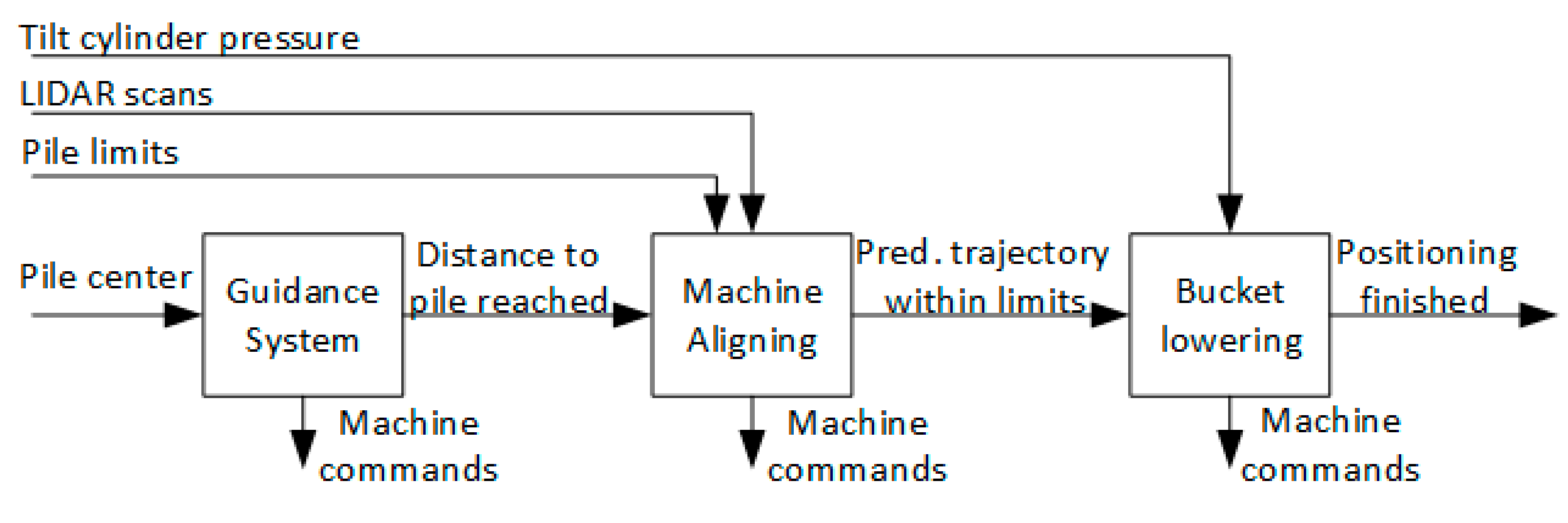
3.3. Positioning and Charging

After the draw point location and status have been determined, the loading routine continues with the positioning of the machine. Here, the LHD is continued to be driven forward using a “guidance” algorithm [34] until the machine’s reference point (in this case its central articulation joint) is at a set distance from the center of the pile (computed as the center of gravity of the segmented points). Once this distance is met, small corrections to the steering angle are issued to ensure that the projected path lands within the limits of the rock pile. Finally, the bucket is lowered until a tight contact with the ground is achieved. A block diagram of this process is shown in Figure 11.
The projected path for the machine aligning procedure (see Figure 12) is computed using the LHD’s kinematic equations, reported in several previous publications, such as [35]:
x , y , θ / t = v   cos θ , v   sin θ , v   sin γ + L r ω / L f cos γ + L r
γ / t = ω
where x , y , θ is the pose of the LHD, v is the linear speed, γ is the steering angle of the LHD’s pivot, ω = γ ˙ is the steering speed of the LHD’s pivot, L r is the length from the LHD’s pivot to the rear wheel axis, and L f is the length from the LHD’s pivot to the front wheel axis.
Since the next step of the autonomous loading routine, the charging against the rock pile, does not involve steering commands, a fixed steering angle (constant γ, ω = 0) can be considered, which simplifies the model:
x , y , θ / t = v   cos θ , v   sin θ , v · K
where K is a constant value that depends on the LHD dimensions and the fixed steering angle. Equation (3) shows that an LHD charging against a rock pile will follow a circular trajectory, characterized by a center ( C ) and a curvature radius ( R ). Because the rock pile identification step computed the left ( E L ) and right ( E R ) pile edges, the problem of determining if the LHD will collide with the rock pile simplifies to checking if the line between E L and E R intersects with both the circular path of the left and right sides of the LHD. Figure 12 shows a diagram of the described scenario.
The solution for the intersection between a circle and a line segment is well known in the common literature and it involves computing the following discriminant value:
Δ = 2   E · E C 2 4 E 2 E C 2 R 2  
where E is the vector going from E R to E L and E C is the vector going from E R to C . If Δ results in a negative value, then the infinite line defined by the points E R and E L never intersects the given circular path. On the other hand, if Δ is positive, a solution exists. Let S 1 and S 2 be solutions to the intersection between the infinite line defined by E R and E L and the circle of center C and curvature radius R :
S 1 = 2   E · E C Δ 2 E S 2 = 2   E · E C + Δ 2 E
then, if 0 < S 1 < 1 or 0 < S 2 < 1 , the circular path intersects the segment E L E R ¯ . Otherwise, if min S 1 ,   S 2 < min S 1 1 ,   S 2 1 , the circular path passes to the right of the segment E L E R ¯ . If none of the previous conditions is met, then the path passes to the left of segment E L E R ¯ .
The above process is executed for the circular paths defined by the left and right side of the LHD. If one of them does not intersect the pile, the steering angle is adjusted in the appropriate direction until both paths land within the rock pile limits. During this steering adjustment, a simple collision check is computed periodically over a bounding box for each body of the LHD. Figure 13 shows a diagram of the collision check for the front body of the LHD. A bounding box is defined for the front body. Then, vectors going from the bottom left corner to the top left corner ( S f ) and to the bottom right corner ( B f ) are defined. In order to check if point P of the detected tunnel wall is inside the bounding box (and hence causing a collision), the following condition is evaluated:
0 < S f · d f < S f 2   0 < B f · d f < B f 2
where d f is the vector going from the bottom left corner of the bounding box to point P . If the condition is true, then point P is inside the collision bounding box.
Once the machine’s steering angle has been adjusted so that its projected path lands within the rock pile limits, the bucket of the LHD is lowered using the tilt hydraulic cylinder. The tilt cylinder is commanded to extend until the pressure in its hydraulic line rises over a predefined threshold, signaling a tight contact between the bucket tip and the ground. An example from full-scale experimental data is shown in Figure 14, where a threshold of 23 bars was selected.
If the above positioning process is not completed within a predefined time limit (in the experiments, a threshold of 30 s was used), an operator assistance request is generated, effectively putting the system in the positioning assistance state from Figure 6. Otherwise, once the vehicle is in position and with the bucket down, it is commanded to drive forward in first gear. The transition to the excavation phase occurs as the collision with the rock pile is detected by a patented method that analyzes the machine’s transmission pressure (engine load) and a skidding factor, estimated from the LIDAR odometry and the machine’s tachometer data [18]. A block diagram is shown in Figure 15.
The skidding estimator from Figure 15 computes the skidding factor with the following formula:
s k i d = v T v L / v M m
where s k i d is the skidding factor; v T is the speed measured from the machine’s tachometer; v L is the speed estimated with the LIDAR-based odometry method mentioned in Section 3.2., and v M m is a normalizing factor, computed as the maximum between v T and v L in a fixed time window.
Simultaneously, the collision detector module monitors the pressure of the hydrostatic transmission system (for the used LF11H LHD, this variable correlates with the engine’s power output). If either the skidding factor or the transmission pressure rises above a predefined threshold, a collision detection event is flagged. Figure 16 shows a plot of the skid factor and the transmission pressure signals, alongside the tilt command, for a teleoperated loading maneuver. The collision with the rock pile happens just before the human operator activates the tilt command. As mentioned above, a significant rise in the transmission pressure, and of the skidding factor, can be seen at that point. Extensive analysis of experimental data, such as shown in Figure 16, led to transmission pressure threshold to be set at 300 bar, and the skidding factor threshold at 0.5.
If a collision detection is not generated within a predefined time limit (in the experiments, a threshold of 10 s was used), an operator assistance request is issued, forcing the system into loading assistance state from Figure 6.

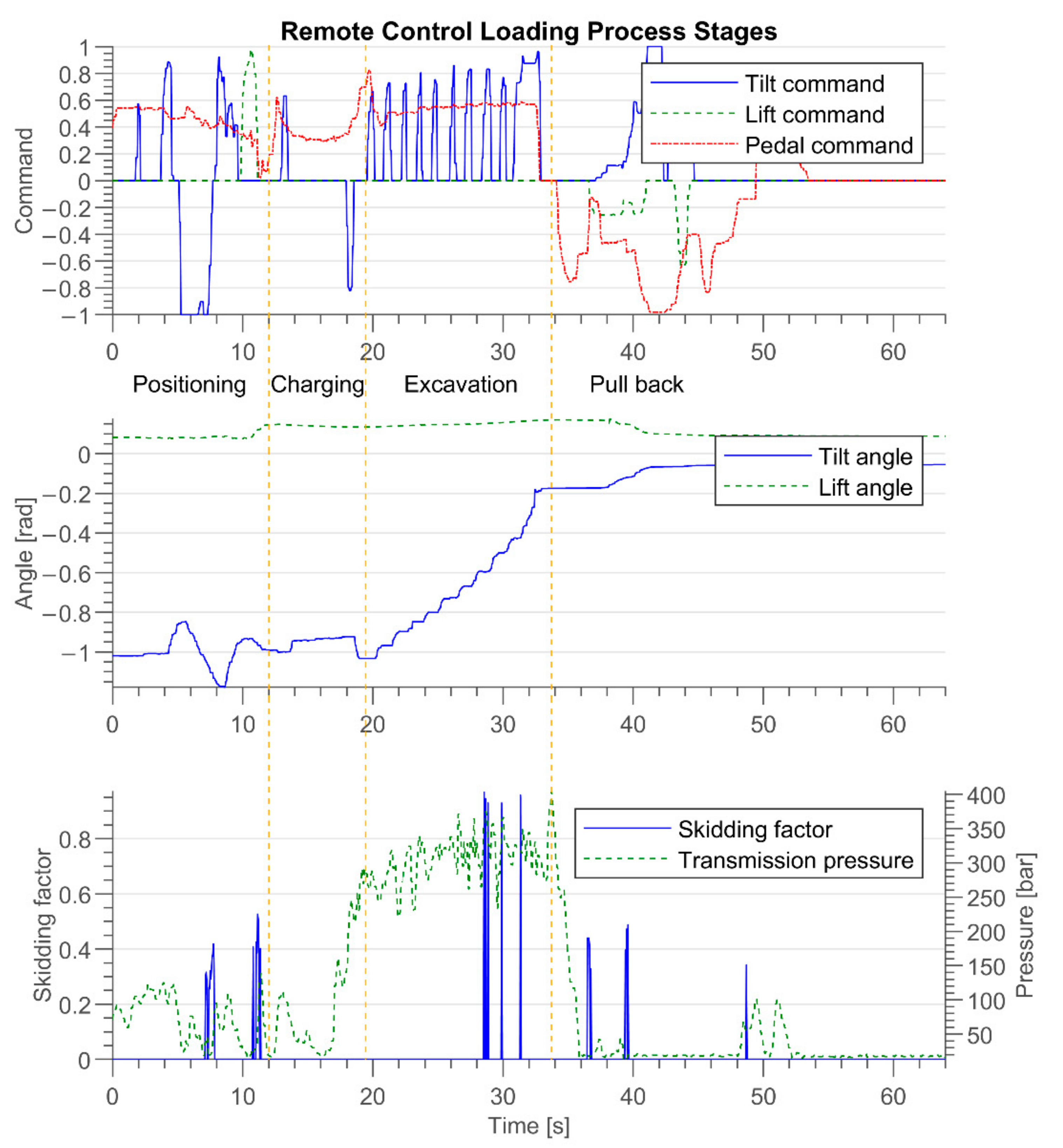
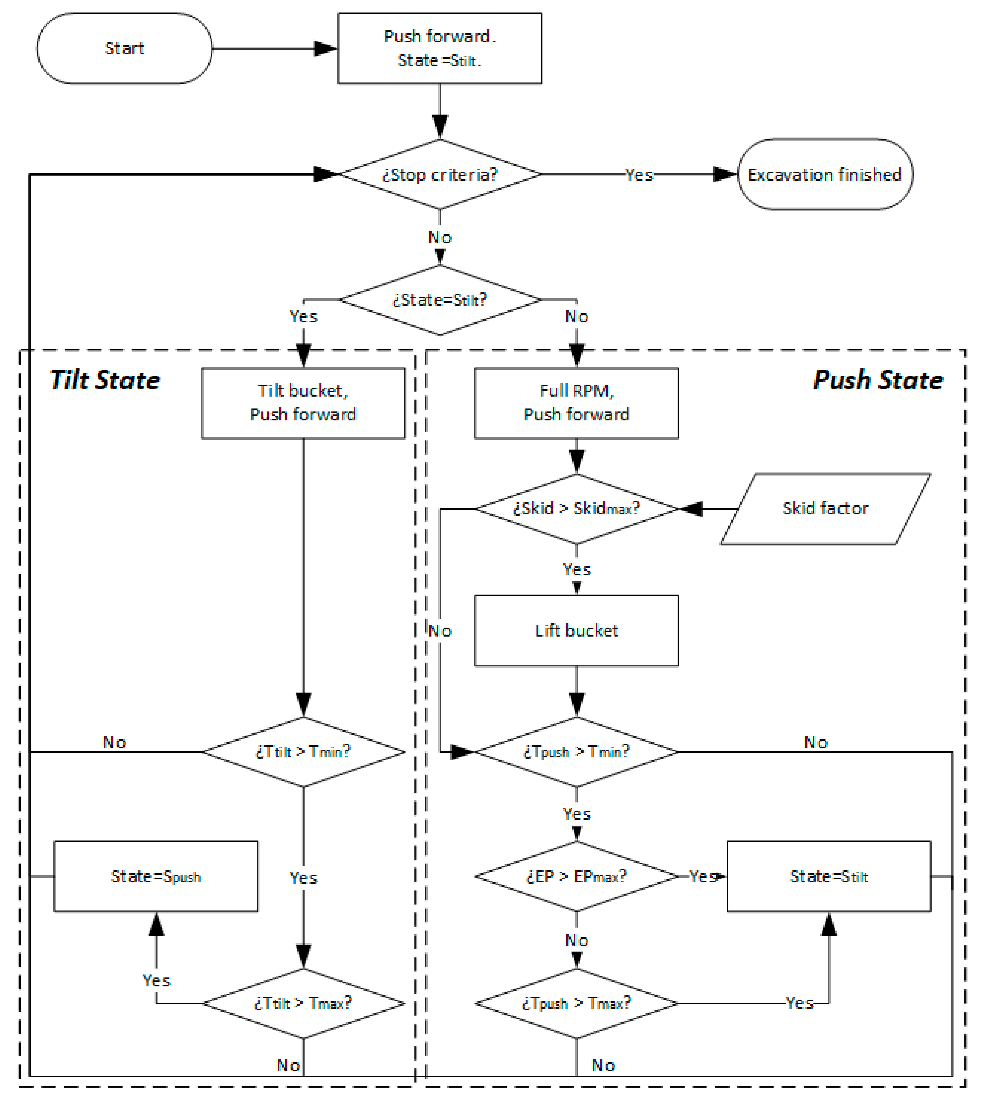
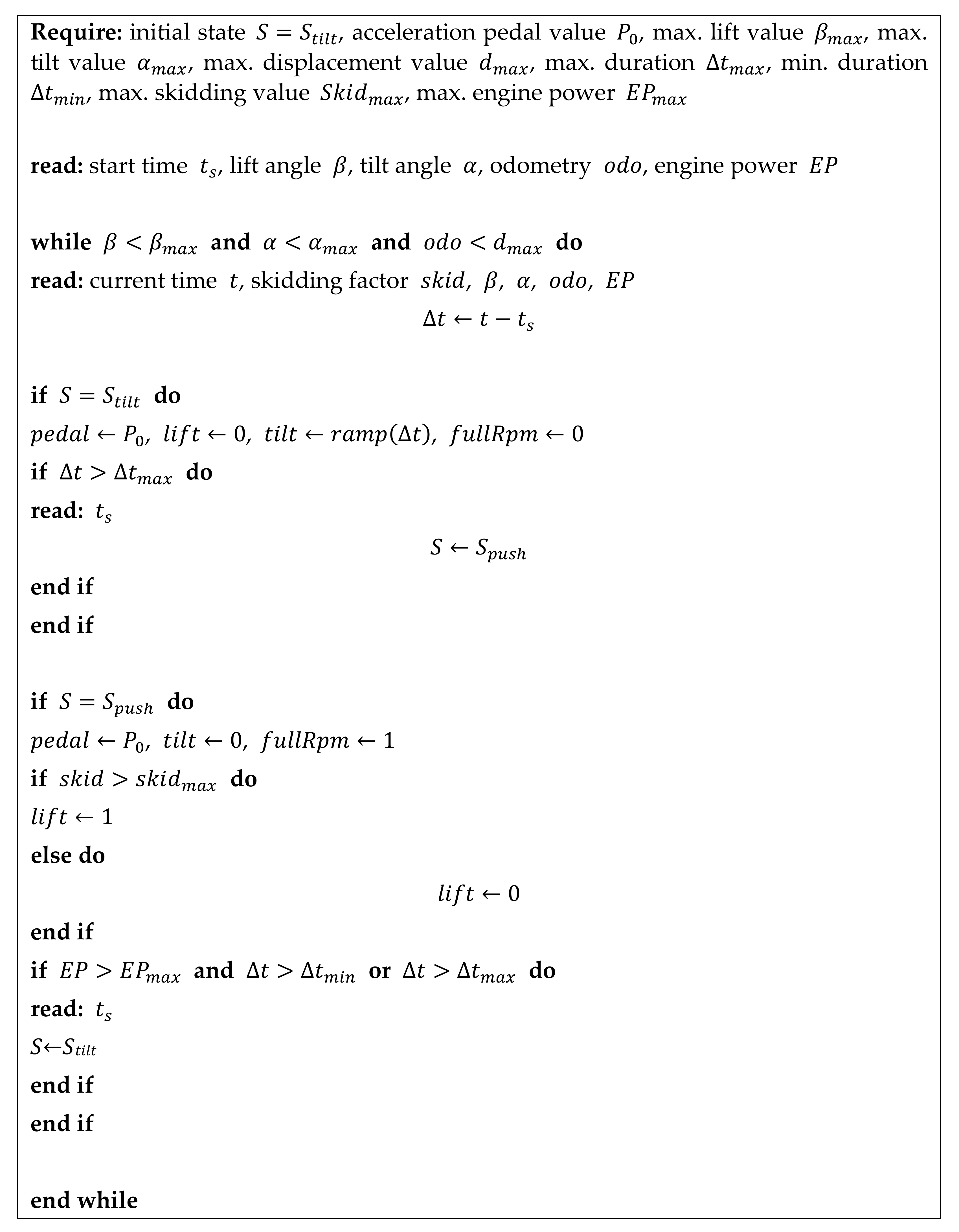
3.4. Excavation Algorithm

The excavation algorithm is based on the techniques used by experienced human operators from block caving, panel caving and sublevel stoping operations (which are the most common type of underground operations in Chile). From a control theory point of view, the proposed method acts as a traction controller during the excavation process. A diagram is shown in Figure 17. The pregenerated commands is simply a module in charge of generating precomputed commands for the pedal and tilt signals. These commands are similar to the commands observed during manual operation. Specifically, the acceleration pedal is maintained at a constant output value and the bucket tilt is intermittently activated in the form of a ramp function. A ramp function was only selected in order to have an extra parameter, although a parameter sensibility analysis could not be performed in the full-scale experiments due to time constrains. The traction controller acts on the lift command in order to suppress wheel skidding, a variable that is estimated from Equation (7), as explained in Section 3.3. In practice, a simple “on/off” controller was implemented, where the lift command was set at the maximum value if the estimated skidding factor raised over a predefined threshold. This choice was made to keep the methods simple in favor of achieving a validation of the complete system.
The implementation of the excavation method was carried out using a two-state machine. In the first state, called S t i l t , a fixed acceleration and a ramp-shaped bucket tilt command are selected. In the second state, called S p u s h , the fixed acceleration command persists, and wheel skidding is analyzed. If the wheel-skidding factor rises above a predefined threshold, the boom lift command of the machine is activated in order to compensate for it. A machine-specific option, named “full RPM”, is also activated during this state. This option forces the engine to maximize its power output, providing additional penetration force. Formally, the following equations apply for the machine commands:
p e d a l = P 0 t i l t = R 0 t t t i l t 1 0 i f s t a t e = S t i l t b t t t i l t 1 i f s t a t e = S t i l t b t t t i l t > 1 i f s t a t e = S p u s h l i f t = 0 1 i f s t a t e = S t i l t s k i d < s k i d m a x i f s t a t e = S p u s h s k i d s k i d m a x f u l l R p m = 0 1 i f s t a t e = S t i l t i f s t a t e = S p u s h
where P 0 , R 0 , and s k i d m a x are predefined constant values; t t i l t is the start time of state S t i l t , and s k i d is the skidding factor. As for the output commands, p e d a l is the signal sent to the machine’s internal control unit that regulates acceleration (similar to the signal sent when pressing the physical pedal in the machine’s cabin), t i l t is the signal sent to retract (positive values) or extend (negative values) the cylinder that controls the movement of the bucket of the LHD machine, and l i f t is the signal that commands the “boom” cylinder of the machine, that is, the arm that can lift (positive values) or lower (negative values) the bucket. Finally, the f u l l R p m signal is, as mentioned, a machine-specific command that forces the engine’s RPM to the maximum, temporarily increasing the force of the hydraulic mechanism. It should be noted that analysis and correction of wheel skidding is only performed during the S p u s h state. This decision was made based on the empirical observation that wheel skidding is much less likely to occur during bucket retraction and the fact that activating the lift cylinder effectively reduces the power available for the tilt hydraulics. In Figure 18, a flow chart of the excavation process is presented, where EP represents engine power (a variable observed, in this case, through the transmission pressure of the machine).
Both states, S t i l t (tilt state) and S p u s h (push state), have upper and lower bounds to their execution time, so it is guaranteed that their execution alternates during the excavation. Besides the time limit of S p u s h , the system can transition back to S t i l t if the hydrostatic transmission pressure (or, more generally, the engine power output) climbs over a threshold value, meaning that the resistive force from the rock pile is too large, and the bucket is not able to penetrate further without a scooping motion. This alternation between states continues until any of the following stop criteria are met: the bucket is fully retracted, the bucket is lifted over a maximum angle, or the machine has advanced further than a maximum displacement value. This method was patented as reported in [36]. For clarity purposes, a pseudo code of the described algorithm is shown in Figure 19. Table 1 shows the value of the parameters used for the full-scale validation experiments reported in Section 4. The numerical values were selected based on operation data.
In the case that the described excavation process is not completed within a predefined time limit (in the experiments, a threshold of 30 s was used), an operator assistance request is generated, thus putting the system in the loading assistance state from Figure 6.

3.5. Pull Back and Payload Weighing

Once the excavation is finished, the bucket gets fully retracted and the vehicle is driven backwards, using the same “guidance” navigation module from the positioning step. A predefined time limit is assigned to this step (in the experiments, 60 s were used). If a timeout occurs, the system is put in the loading assistance state from Figure 6.
After a predefined distance has been covered within the aforementioned time limit, the bucket is commanded to perform short downward and upward tilting movements, known as the “bucket shake”. Then, the bucket is lifted up to a fixed angle ( β w e i g h ), and the pressure sensors in the boom hydraulic line are used to estimate the bucket fill factor. A fill factor is used instead of the mass weight, since it simplifies calibration, while providing the same information for the evaluation process. The relationship between the lift cylinder pressure ( P ) and the fill factor was found experimentally and corresponds to the following affine model:
f f i l l = m P n
where f f i l l is the relative fill factor (0 for an empty bucket and 1 for a full bucket), and m and n are the constants to be calibrated through experimentation. Table 2 shows the parameters used for the particular conditions of the field trials presented in this work (machine and rock characteristics).

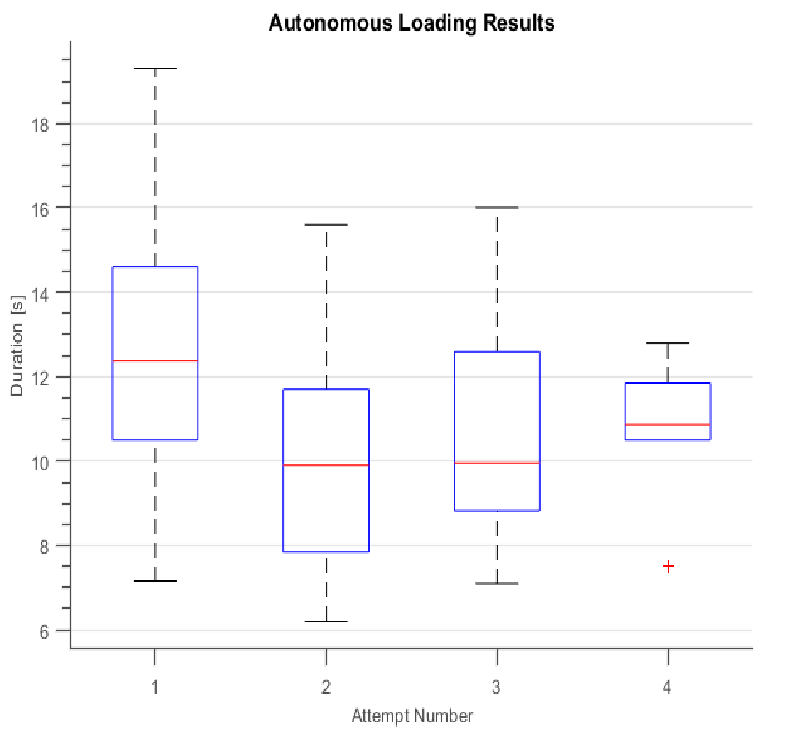
4. Experiments and Analysis

Full-scale experiments with a GHH LF11H model LHD (see picture in Figure 1) were carried out in a production tunnel of a sublevel stoping mine located in the Coquimbo Region (Chile), facilitated by the Chilean mining company, CMSG. Pictures of the mine site and the LHD inside its tunnel are shown in Figure 20. Figure 20a shows the mechanical workshop just outside the mine’s main entrance, and Figure 20b shows the LHD during surface tests. Figure 20c shows the LHD outside the test tunnel with an almost fully loaded bucket.
Figure 21 shows the layout of the tunnel where experiments were carried out. The LHD traveled from the “start–end point” shown in the figure to the end of the red line, where the stope was originally located. A stope is a large open underground space that is produced by the sublevel stoping mining method. The LHDs load ore inside the stope from a large pile of material, also sometimes referred to as the loading point or draw point. Once the LHD has a fully loaded bucket, it has to travel back to the “start–end point” to dump the ore.
The experiments reported here were carried out in a fully functional tunnel of the mine, i.e., a tunnel used for extracting mineral. In fact, the experiments took place during day hours, while the mine’s night shift used the LHD in manual mode for production. As a result of this, the shape and location of the stope and the draw point changed every day (as the ore runs out, the inner wall of the stope is blasted as part of the mining process).
Because of this, and since in situ experimentation was time-limited, experiments were separated in two parts. First, the field trial experiments regarding charging and collision detection of the LHD and the pile, and the LHD’s excavation and payload weighing, are reported in Section 4.1. Then, pile identification experiments from an offline processing of the collected field data are presented in Section 4.2.
The mining tunnel was narrower than recommended by the LHD manufacturer, so the LHD’s positioning was more complex than initially expected. This also contributed to dividing the experiments into the two groups described above. Figure 22 shows a picture of the draw point as seen from the teleoperation system cameras.

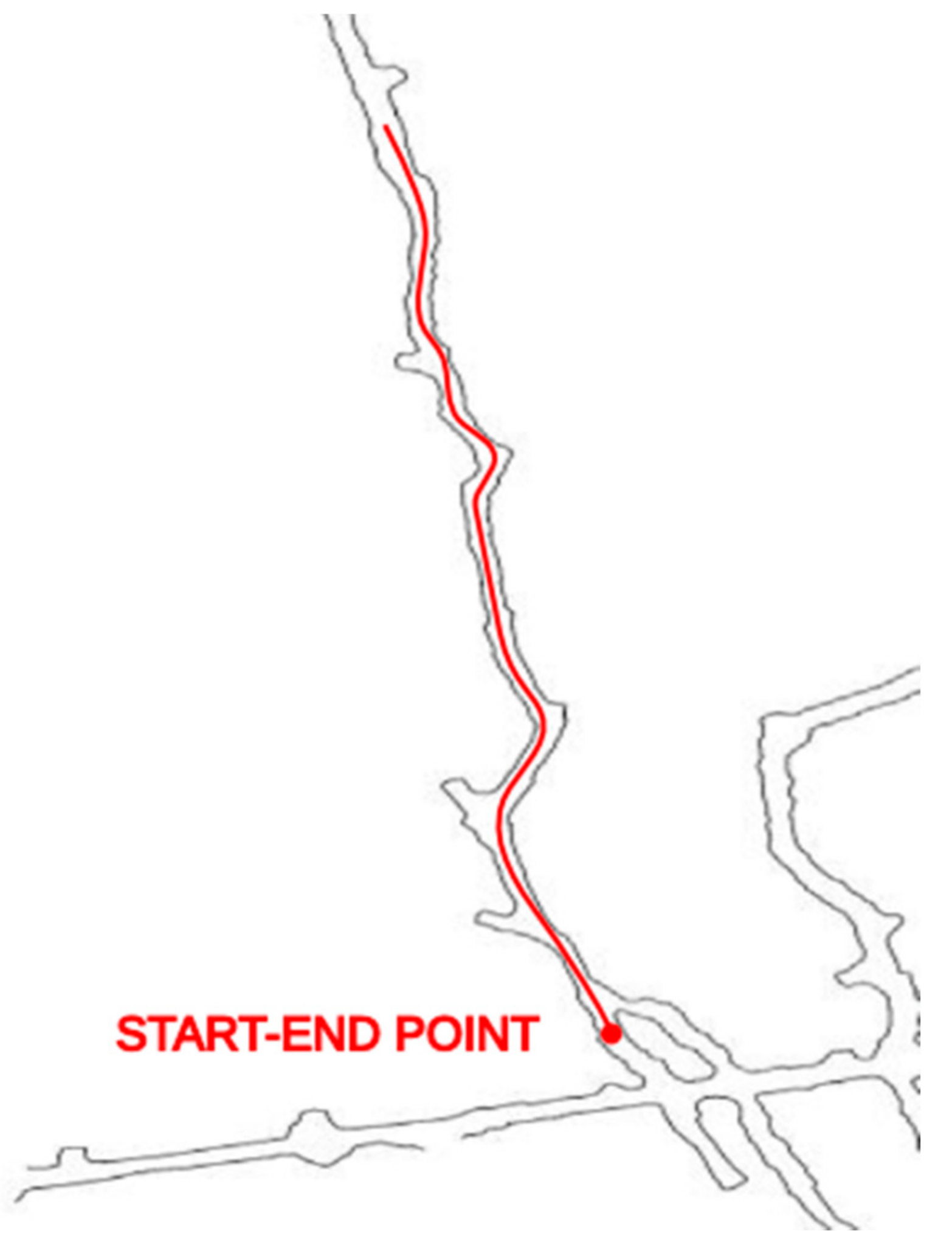
4.1. Full-Scale Rock Excavation Experiments

Since the pile identification method was not fully optimized at the time of the onsite tests, and time for executing the experiments in the mine was limited, the development team divided the loading procedure in two stages in order to maximize the total number of full-scale rock excavation experiments and evaluate each stage separately. One stage included rock pile identification and positioning, and the other included the charging, excavation, pull back, and weighting processes. To perform this, loading experiments required a human operator to position the machine five to ten meters in front of the draw point, effectively bypassing the rock pile identification and positioning stages, and starting the system’s state machine in “positioning assistance”, as described in Section 3.
A total of 30 complete loading experiments were carried out. Similar to in manual operation, multiple loading attempts were required in order to fill the bucket during each experiment. Manual operation of LHD in sublevel stoping mines usually needs two or three attempts to achieve a proper bucket fill factor, since the procedure is performed using line-of-sight radio control with limited visibility behind the LHD (safety regulations forbid operators to enter the stope area). In some attempts, the tip of the bucket was lowered too much, causing high resistive forces from the ground during charging, and thus triggering the collision detection too early. A total of 81 loading attempts were performed in order to fulfill the 30 complete loads. Of these, 7 failed (early collision trigger) and 74 were successful, resulting in the 91% success rate of the charging and collision detection method.
For each experiment, a fixed value of 0.5 was used for the pedal command. An operator monitoring the system’s behavior during the complete loading process from a remote-control station decided when the bucket was full enough, and hence if a new attempt was needed. The operator relied only on the visual input of the machine’s forward camera to make this decision.
Figure 23 shows an example of the relevant variables in an autonomous loading attempt, which has some resemblance to the operator-controlled loading shown in Figure 5.
Table 3 shows the number of experiments carried out, classified by the number of attempts to achieve a full bucket, and the average fill factor for each category. It can be seen that most experiments required three loading attempts, and that the operator continued to reattempt loading until the fill factor was about 90%. This can be seen more easily on Table 4, where the average fill factor and average number of attempts for all experiments are shown. It must be noted that while the fill factor at the end of each experiment met the criteria for manual operation (since it was the same operator deciding when the bucket was full), the average number of attempts was found to be higher than that in manual operation, which, according to manual operators was between two and three attempts.
Table 5 and Figure 24 and Figure 25 show more detail about progressive filling of the bucket through loading attempts for the 30 loading experiments. Table 5 shows the average durations of the excavation step and the resulting fill factor, classified according to the progressive sequence of attempts, as well as the total number of experiments in each case. On average, the first attempt managed to fill 62% of the bucket capacity; then, the second attempt achieved 77%; the third attempt achieved 82%; and for the six experiments that needed a fourth attempt, the average that resulted was a 90% fill factor. The average excavation duration was about 10–12 s, which comprised the time between the collision of the LHD with the rock pile and the end of the excavation algorithm. The required time for positioning, charging, and weighing was not taken into account in this measurement. It can be seen that the average duration of the excavation in the first attempt is slightly longer than the others.
Figure 24 shows a box plot of the excavation step duration for all loading attempts. The time taken for the excavation ranges from 6 to almost 20 s, depending on the conditions of the rock pile and the specific interaction between the bucket and the rock pile. Figure 25 shows a box plot of the fill factor that was obtained progressively through loading attempts. It can be seen that the biggest jump in performance happened in the second loading attempt. Some outliers with performance above 100% are also depicted for the second and third attempts and appear as a consequence of loading a large boulder.
During experimentation, the value of accurately placing the bucket of the machine against the ground, prior to the charging against the rock pile, was recognized. A bucket tilted too far down would cause an early trigger of a collision detection, while a bucket tilted just slightly upwards has a relevant impact on how far the machine can penetrate into the rock pile. An even more relevant factor that affects the performance of the loading maneuver is the status of the rock pile. Newly blasted ore is far easier to load than draw points that have had more time to settle and compress due to the weight of the rock. Draw points with large amounts of ore are also easier to load than those that have little material left. Despite these relevant factors, the proposed method was able to extract full buckets each time, at the expense of the operator having to perform more than the usual number of reattempts required under manual operation.
It is important to note that in a real mining operation, the efficiency of an LHD is measured in the amount of ore that it is able to haul from the extraction point to the dumping point (usually in tons/hour). Therefore, the percentage of bucket filling is not the only relevant factor when evaluating the system, but also the amount of time it uses to load the bucket. This is especially important when deciding if the system should make another attempt at the excavation procedure to achieve a fuller bucket. This criterion varies among different operations, as the dumping and haulage time is different.

4.2. Offline Results Using Field Data: 2.5D Modeling of the Extraction Point

Personnel cannot be inside a stope as it is forbidden for security reasons (i.e., rock can fall from the ceiling of the stope), so it was not possible to obtain accurate measurements of the ore pile characteristics. However, an accurate modeling of the ore pile is not really necessary, as it only needs to be detected, as well as having its width and inclination roughly estimated in order for the excavation algorithm to work.
To obtain the datasets required to characterize our 2.5D modeling algorithm, the LHD was driven from a fixed distance of about 50 m from the loading point to the entrance of the stope, while all sensor and machine data was recorded. These datasets were captured at different times so the drawing point was not located in the same place, nor did the ore pile have the same shape. First, in each case the point cloud was computed and then the pile’s width and inclination estimated. Figure 26 shows an example of the point cloud obtained while the LHD is approaching an extraction point, after registering the position of the points using the LIDAR-based odometry and the inclinometer data (see details in Section 3.2). The color of the points represents the distance to the LHD (in the x-axis) at the time of registration. In the case of the rock pile at the end of the tunnel, red indicates that the machine was further away when that reading was taken.
The results of several modeling attempts where the pile’s width and inclination were estimated are summarized in Table 6. They consider ground truth width, predicted width, ground truth inclination, and predicted inclination. Both ground truth width and ground truth inclination were determined manually from the integrated point clouds. The average absolute error in the predicted width is 0.58 m, while the average absolute error in the inclination is 1.7 degrees. The precision achieved by the characterization procedure is sufficient for the task of autonomous loading.

5. Conclusions

A complete autonomous loading system for LHD machines for underground mining was presented. The loading system considers identification of the rock pile, positioning of the machine in front of it, charging against the rock pile, excavating, moving away from the draw point, and estimating the bucket weight or fill factor. Despite that the proposed system was fully implemented (including the necessity for a human operator to be involved in the process in order to complete the task when the system fails), it could not be tested as a whole. The proposed system which implements the whole loading process, the excavation algorithm, and the tests in a real production environment are the most important contributions of this work.
The experimentation phase was divided between onsite execution and validation of the excavation algorithm, and offline data processing for the rock pile identification method. In the onsite experiments, identification and positioning were bypassed in favor of teleoperation by a human operator. It was also the operator’s choice whether or not to perform multiple loading attempts in order to fill the bucket. A total number of 30 excavation experiments were carried out, most of them requiring multiple attempts to achieve a full bucket. An average of 3.6 attempts per experiment was needed in order to obtain a bucket fill factor of 90%. By comparison, manual operation usually needs two or three attempts to achieve this bucket fill factor. This performance may seem inferior to previous published work: however, there are other factors involved that prevent direct comparison of the results. Equipment, type of ore, and mining method should be considered. Thus, comparison to the human operators of the specific mining site should be preferred. It is important to mention that the main driver for automating the loading process is to increase the safety of workers rather than obtain higher efficiency. In this regard, the proposed excavation algorithm fulfills our expectations.
Since these experiments are time-consuming in an industry where time is an expensive resource, only enough experiments needed to validate the excavation algorithm were able to be executed. Part of our future work will be to carry out new experiments in an underground mine in order to validate the complete autonomous loading system, and to measure its performance more accurately. Despite this, the problem remains relevant and mining companies are looking forward to integrating autonomous loading to LHDs in their operations, as it would enable them to close the loop for a fully autonomous production cycle.
A video showing the operator’s graphic interface while the system is autonomously performing an excavation procedure can be found in https://youtu.be/Oa11kTBJf2Y (accessed on 7 September 2021).
The system is now being installed and tested in a room and pillar mine in Germany, where it will be tested as a whole system.

Author Contributions

Conceptualization, C.T., M.M. and J.R.-d.-S.; methodology, M.M., C.T. and J.R.-d.-S.; software, C.T.; validation, M.M. and C.T.; resources, J.R.-d.-S.; data curation, C.T.; writing—original draft preparation, C.T., M.M. and J.R.-d.-S.; writing—review and editing, C.T., M.M. and J.R.-d.-S.; funding acquisition, J.R.-d.-S. All authors have read and agreed to the published version of the manuscript.

Funding

This research was funded by the Chilean National Research Agency ANID under project grant Basal AFB180004 and FONDECYT 1201170.

Institutional Review Board Statement

Not applicable.

Informed Consent Statement

Not applicable.

Data Availability Statement

The data presented in this study is contained in the article itself.

Acknowledgments

We thank Paul Vallejos for the valuable discussions and support for onsite execution of the experiments; we thank David Leottau for his valuable work in the early implementations of the 2.5D modeling of the ore pile. We also thank Patricio Loncomilla and Martin Calvo for their valuable work enhancing the 2.5D modeling algorithm and its associated results. We also acknowledge Compañía Minera San Gerónimo for providing the mine infrastructure for testing the system, and GHH Chile for supplying the LHD machine needed for this work.

Conflicts of Interest

The authors declare no conflict of interest.

References

  1. Salvador, C.; Mascaró, M.; Ruiz del Solar, J. Automation of Unit and Auxiliary Operations in Block/Panel Caving: Challenges and Opportunities; Massmin: Santiago, Chile, 2020. [Google Scholar]
  2. Scheding, S.; Nebot, E.M.; Stevens, M.; Durrant-Whyte, H.; Roberts, J.; Corke, P.; Cunningham, J.; Cook, B. Experiments in Autonomous Underground Guidance. In Proceedings of the 1997 IEEE International Conference on Robotics and Automation, Albuquerque, NM, USA, 25–25 April 1997; pp. 1898–1903. [Google Scholar]
  3. Cunningham, J.; Roberts, J.M.; Corke, P.; Durrant-Whyte, H. Automation of Underground LHD and Truck Haulage. In Proceedings of the AusIMM Annual Conference—“The Mining Cycle” (AUSIMM 1998), Mount Isa, Australia, 19–23 April 1998. [Google Scholar]
  4. Mäkelä, H. Overview of LHD Navigation without Artificial Beacons. Robot. Auton. Syst. 2001, 36, 21–35. [Google Scholar] [CrossRef]
  5. Duff, E.S.; Roberts, J.M.; Corke, P.I. Automation of an underground mining vehicle using reactive navigation and opportunistic localization. In Proceedings of the 2003 IEEE/RSJ International Conference on Intelligent Robots and Systems, Las Vegas, NV, USA, 27–31 October 2003; Volume 3, pp. 3775–3780. [Google Scholar]
  6. Larsson, J. Reactive Navigation of an Autonomous Vehicle in Underground Mines. Ph.D. Thesis, Örebro University, Örebro, Sweden, 2007. [Google Scholar]
  7. Hemami, A. Modelling, analysis and preliminary studies for automatic scooping/loading in a mechanical loader, International Journal of Surface Mining. Reclam. Environ. 1992, 6, 151–159. [Google Scholar]
  8. Hemami, A. Study of bucket trajectory in automatic scooping with load-haul-dump loaders. Trans. Inst. Min. Metall. 1993, 102, 37–42. [Google Scholar]
  9. Ji, Q.; Sanford, R.L. Autonomous excavation of fragmented rock using machine vision. In Emerging Computer Techniques for the Minerals Industry; Society for Mining Metallurgy: Englewood, CO, USA, 1993; pp. 221–228. [Google Scholar]
  10. Hemami, A. Study of forces in the scooping operation of a mechanical loader. Trans. Can. Soc. Mech. Eng. 1994, 18, 191–205. [Google Scholar]
  11. Petty, M.K.; Billingsley, J.; Tran-Cong, T. Autonomous LHD loading. In Proceedings of the Fourth Annual Conference on Mechatronics and Machine Vision in Practice, Toowoomba, QLD, Australia, 23–25 September 1997. [Google Scholar]
  12. Takahashi, H.; Hasegawa, M.; Nakano, E. Analysis on the resistive forces acting on the bucket of a load-haul-dump machine and a wheel loader in the scooping task. Adv. Robot. 1999, 13, 97–114. [Google Scholar] [CrossRef]
  13. Marshall, J.A.; Murphy, P.F.; Daneshmend, L.K. Toward autonomous excavation of fragmented rock: Full-scale experiments. IEEE Trans. Autom. Sci. Eng. 2008, 5, 562–566. [Google Scholar] [CrossRef]
  14. Hemami, A.; Hassani, F. An overview of autonomous loading of bulk material. In Proceedings of the 26th International Symposium on Automation and Robotics in Construction, Austin, TX, USA, 24–27 June 2009. [Google Scholar]
  15. Dobson, A.; Marshall, J.; Larsson, J. Admittance control for robotic loading: Design and experiments with a 1-tonne loader and a 14-tonne load-haul-dump machine. J. Field Robot. 2017, 34, 123–150. [Google Scholar] [CrossRef] [Green Version]
  16. Heshan, F.; Marshall, J.A.; Almqvist, H.; Larsson, J. Towards Controlling Bucket Fill Factor in Robotic Excavation by Learning Admittance Control Setpoints. In Field and Service Robotics; Springer: Cham, Switzerland, 2018. [Google Scholar]
  17. Heshan, F.; Marshall, J.A.; Larsson, J. Iterative learning-based admittance control for autonomous excavation. J. Intell. Robot. Syst. 2019, 96, 493–500. [Google Scholar]
  18. Ruiz del Solar, J.; Vallejos, P.; Tampier, C.; Leottau, D. Un Método de Estimación de Derrape y Detección de Colisión con una Pila de Mineral. Chilean Patent 201803481, 8 July 2020. [Google Scholar]
  19. Erikson, J.M.; Mueggenburg, N.W.; Jaeger, H.M.; Nagel, S.R. Force distributions in three-dimensional compressible granular packs. Phys. Rev. E 2002, 66, 040301. [Google Scholar] [CrossRef] [PubMed] [Green Version]
  20. Herminghaus, S. Dynamics of wet granular matter. Adv. Phys. 2005, 54, 221–261. [Google Scholar] [CrossRef]
  21. Mikhirev, P.A. Design of automated loading buckets. Sov. Min. 1986, 22, 292–298. [Google Scholar] [CrossRef]
  22. Shi, X.; Lever, P.; Wang, F. Experimental robotic excavation with fuzzy logic and neural networks. In Proceedings of the 1996 IEEE International Conference on Robotics and Automation, Minneapolis, MN, USA, 22–28 April 1996; Volume 1, pp. 957–962. [Google Scholar]
  23. Dobson, A.; Marshall, J. Autonomous Loading Vehicle Controller. WO Patent 2015/109392, 30 July 2015. [Google Scholar]
  24. Rocke, D.J. Control System for Automatically Controlling a Work Implement of an Earth Working Machine to Capture Material. U.S. Patent Application No. 5,528,843, 25 June 1996. [Google Scholar]
  25. Alshaer, B.J.; Ingram, R.G.; Krone, J.J.; Berry, J.K.; Harris, J.J. Automatic Digging and Loading System for a Work Machine. U.S. Patent Application No. 7,555,855, 7 July 2009. [Google Scholar]
  26. Fletcher, J.G.; Jones, D.A.; Hewavisenthi, R.D.; Chow, R.K. Excavation System Having Adaptive Dig Control. U.S. Patent Application No. 09,587,369, 7 March 2017. [Google Scholar]
  27. Asenjo, R.; Boulard, A.; Mascaró, M.; Tampier, C.; Ruiz del Solar, J. Autonomous Loading for an LHD. In Proceedings of the Automining 2016, Antofagasta, Chile, 30 November–2 December 2016. [Google Scholar]
  28. Quigley, M.; Conley, K.; Gerkey, B.; Faust, J.; Foote, T.; Leibs, J.; Wheeler, R.; Ng, A. ROS: An Open-Source Robot Operating System; ICRA Workshop on Open Source Software. 2009. Available online: http://www.cim.mcgill.ca/~dudek/417/Papers/quigley-icra2009-ros.pdf (accessed on 7 September 2021).
  29. Röfer, T. CABSL—C-Based Agent Behavior Specification Language. In RoboCup 2017: Robot World Cup XXI; Springer: Cham, Switzerland, 2017; pp. 135–142. [Google Scholar]
  30. Koenig, N.; Howard, A. Design and use paradigms for gazebo, an open-source multi-robot simulator. In Proceedings of the 2004 IEEE/RSJ International Conference on Intelligent Robots and System, Sendai, Japan, 28 September–2 October 2004; Volume 3, pp. 2149–2154. [Google Scholar]
  31. Leottau, D.; Loncomilla, P.; Mascaró, M.; Tampier, C.; Ruiz del Solar, J. LIDAR-based odometry estimation for autonomous loading of material with LHD. In Proceedings of the Massmin 2020, Santiago, Chile, 9–11 December 2020. [Google Scholar]
  32. Jaimez, M.; Monroy, G.; Gonzalez, J. Planar Odometry from a Radial Laser Scanner. A Range Flow-based Approach. In Proceedings of the IEEE International Conference on Robotics and Automation, Stockholm, Sweden, 16–21 May 2016. [Google Scholar]
  33. Lobos, K.; Loncomilla, P.; Ruiz-del-solar, J. Rocky-YOLO: Detección de rocas usando deep learning para aplicaciones en minería. In Proceedings of the SIMIN 2019, Santiago, Chile, 21–23 August 2019. (In Spanish). [Google Scholar]
  34. Mascaró, M.; Tampier, C.; Ruiz del Solar, J. Topological Navigation in Tunnels: LHD Navigation as a Case Study. In Proceedings of the Automining 2020, Santiago, Chile, 30 November–4 December 2020. [Google Scholar]
  35. Marshall, J.; Barfoot, T.; Larsson, J. Autonomous underground tramming for center-articulated vehicles. J. Field Robot. 2008, 25, 400–421. [Google Scholar] [CrossRef]
  36. Ruiz del Solar, J.; Vallejos, P.; Tampier, C. Método de Carguío Autónomo Para Cargadores Frontales. Chilean Patent 201803004, 26 December 2019. [Google Scholar]
Figure 1. Full-scale LHD machine used during the test of the excavation algorithm.
Applsci 11 08718 g001
Figure 2. Steps of the proposed autonomous loading system.
Applsci 11 08718 g002
Figure 3. Sublevel stoping draw point.
Applsci 11 08718 g003
Figure 4. Excavation method diagram. (a) LHD engages with the rock pile. (b) Bucket tilt used to excavate. (c) Boom lift used to control wheel traction. (d) End of the excavation phase.
Applsci 11 08718 g004
Figure 5. Relevant variables during the loading maneuver: Lift/Tilt command: manual bucket lifting/tilting command. Pedal command: manual machine acceleration command. Transmission Pressure: hydrostatic transmission pressure of the machine. Tilt Angle: tilt angle of the bucket. Lift Angle: lift angle of the boom. Skidding factor: estimated skidding factor. See the definitions of these variables in Section 3.3 and Section 3.4.
Applsci 11 08718 g005
Figure 6. Finite state machine formulation for the autonomous loading with human operators in-the-loop.
Applsci 11 08718 g006
Figure 7. Rock pile identification block diagram. LIDAR odometry and machine’s inclinometer data are used to register 2D laser scans into a 3D model of the environment. A segmentation of the rock pile is then carried out, and its center, limits, and slope are extracted.
Applsci 11 08718 g007
Figure 8. Rock pile reconstruction process through laser-scan integration. As the machine approaches the pile (images (ac)), the new laser scans are merged with the previous ones using the computed odometry. A slightly tilted LIDAR is used for this purpose.
Applsci 11 08718 g008
Figure 9. Pseudo code of pile segmentation and characterization algorithm.
Applsci 11 08718 g009
Figure 10. Point cloud showing pile reconstruction (point color corresponds to the ny component of the normal).
Applsci 11 08718 g010
Figure 11. Positioning block diagram. The machine is driven by a guidance system until a predefined distance to the rock pile is achieved. The steering angle of the LHD is then adjusted to ensure collision with the pile, and the bucket is lowered.
Applsci 11 08718 g011
Figure 12. Intersection of the predicted trajectory with the detected pile limits. Left and right pile limit points denoted as EL and ER, respectively (with the face of the pile between them in a red segmented line). LHD’s left side circular trajectory center and curvature radius denoted with C and R, respectively. In a blue dotted line both sides of the predicted LHD’s trajectory is presented.
Applsci 11 08718 g012
Figure 13. Simple collision check between the front body of the LHD and point P of the detected tunnel wall. Vectors Sf and Bf (in blue) of the collision bounding box are used alongside vector df (in red) to determine if point P is inside the bounding box.
Applsci 11 08718 g013
Figure 14. Cylinder pressure increase as the bucket is tightly pressed against the ground in preparation for the charging maneuver.
Applsci 11 08718 g014
Figure 15. Charging block diagram. The machine is driven forward while a collision detection routine analyzes the machine’s transmission pressure and an estimated skidding factor.
Applsci 11 08718 g015
Figure 16. Detection of the collision with the rock pile. Through analysis of the manual operation data, the transmission pressure signal and the estimated skidding factor were selected and used in a threshold detector.
Applsci 11 08718 g016
Figure 17. Control diagram of the excavation method. Tilt and pedal commands are predetermined from the human operator control method. The lift command is adjusted depending on the detected machine skidding, which is in turn estimated from the LIDAR odometry and machine tachometer data.
Applsci 11 08718 g017
Figure 18. Flow chart of the excavation algorithm.
Applsci 11 08718 g018
Figure 19. Pseudo code of the excavation algorithm.
Applsci 11 08718 g019
Figure 20. LHD machine and mining facility. (a) Mechanical workshop just outside the mine’s main entrance; (b) LHD during surface tests; (c) LHD outside the test tunnel with an almost fully loaded bucket.
Applsci 11 08718 g020
Figure 21. Layout of the mine’s tunnel where experiments were carried out.
Applsci 11 08718 g021
Figure 22. Operator’s point of view of the loading point used for onsite experiments.
Applsci 11 08718 g022
Figure 23. Relevant variables in an autonomous loading attempt.
Applsci 11 08718 g023
Figure 24. Excavation step duration per loading attempt. Red “+” signs represent outliers.
Applsci 11 08718 g024
Figure 25. Progressive fill factor across loading attempts. Red “+” signs represent outliers.
Applsci 11 08718 g025
Figure 26. Example of the scanning obtained while the LHD is approaching an extraction point. (a) Top view of the pile reconstruction. (b) Isometric view of the pile reconstruction.
Applsci 11 08718 g026
Table 1. Excavation method parameters used for the full-scale validation.
ParameterValue
P 0 0.5
R 0 1.2
s k i d m a x 0.2
β m a x 0.5 [rad]
α m a x 0.0 [rad]
d m a x 2.0 [m]
Δ t m a x 1.0 [s]
Δ t m i n 0.5 [s]
E P m a x 300 [bar]
Table 2. Weight model parameters used for the full-scale validation.
ParameterValue
β w e i g h 0.2
m 0.0207
n 1.0774
Table 3. Loading experiments and average fill factor per number of loading attempts. N-Attempts: number of attempts required to fill bucket. N-Exp: number of experiments. Total-Attempts: total number of performed attempts. %-Experiments: % of the experiments. Fill-Factor: average fill factor.
N-AttemptsN-ExpTotal-Attempts%-ExperimentsFill-Factor
1 attempt9930%88%
2 attempts4813%107%
3 attempts113337%87%
4 attempts62420%90%
TOTAL3074100%-
Table 4. Total average number of attempts and fill factors.
Total Average Number of AttemptsTotal Average Fill Factor
3.690%
Table 5. Duration and fill factor in consecutive attempts. P-Attempts: progressive sequence of attempts. N-Exp: number of experiments. Duration: average duration. Fill-Factor: average fill factor.
P-AttemptsN-ExpPercentageDurationFill-Factor
First attempt30100%12.7 s62%
Second attempt2170%10.2 s77%
Third attempt1757%10.8 s82%
Fourth attempt620%10.7 s90%
Table 6. Results of modeling extraction points.
Modeling AttemptGround Truth Width (m)Predicted Width (m)Ground Truth Inclination (°)Predicted Inclination (°)
13.252.89−53.0−52.6
23.105.27−50.1−48.7
33.103.16−52.4−50.5
43.443.29−50.6−50.5
53.203.72−50.0−53.4
63.033.25−49.5−46.5
Publisher’s Note: MDPI stays neutral with regard to jurisdictional claims in published maps and institutional affiliations.

