Article

Granular Stack Density’s Influence on Homogeneous Fluidization Regime: Numerical Study Based on EDEM-CFD Coupling

1
School of Mechanical Engineering, University of Science and Technology Beijing, Beijing 100083, China
2
Central Research Institute of Building and Construction Co., Ltd., Beijing 100088, China
*
Authors to whom correspondence should be addressed.
Appl. Sci. 2021, 11(18), 8696; https://doi.org/10.3390/app11188696
Submission received: 30 March 2021 / Revised: 23 April 2021 / Accepted: 27 April 2021 / Published: 18 September 2021
(This article belongs to the Section Mechanical Engineering)

Abstract

:
FLUENT and EDEM were applied to simulate liquid–solid coupling in a 3D homogenous fluidization. The dynamics of destabilization of the granular material immersed by homogeneous fluidization were observed. The effect of initial packing density of granular stack and fluidization rate on the fluidization’s transient regime, the configuration of particles in the fluidized bed and the variation of bed height were analyzed and discussed. According to the results, there was an original observation of a strong impact of the initial density of an initially static granular stack on the transient fluidization regime. Depending on the material initial volume fraction, there was a difference in grain dynamics. For an initially loose stack, a homogeneous turbulent fluidization was observed, whereas for an initially dense stack, there was a mass takeoff of the stack. The propagation of wave porosity instability, from the bottom to the top of the stack with fast kinetics that decompacted the medium, followed this mass takeoff.

1. Introduction

Many industrial applications rely on fluidized particle bed processes, in most cases induced by a uniform fluid injection [1,2]. The configuration, corresponding to the particular situation where an ascending liquid flow creates a partial fluidization of a granular material, has motivated a large number of studies [3,4,5,6,7,8,9]. The specific situation of the transient expansion phase of the homogeneous fluidization, which corresponds to the case where the injection size reaches the total width of the domain, has attracted all our attention. In this more general topic of hydromechanical instabilities within a drained granular material, we studied, experimentally and numerically, the antagonistic roles of the fluidization and the dilatancy of an initially dense or loose material, controlled by the geometrical confinement imposed by the walls.
Localized fluidization by a gas is also present in some direct industrial applications via spouted bed processes and has resulted in a large number of studies [10,11,12,13,14,15]. Furthermore, for hydraulic structures in earth, the hydraulic flow of infiltration into the foundations generates downstream of the structure an overpressure below the surface layer of the soil, which can cause an overall lifting of the structure granular and possibly hydraulic fracturing (internal erosion) [16,17,18]. Moreover, this underground internal flow, under the effect of a sufficiently high-pressure gradient, can also locally fluidize the soil and form vertical chimneys, possibly leading to the surface (phenomenon of sand boil). On the other hand, water leaks in underground pipes, for the distribution and drain of wastewater, can erode granular soil particles. Underground cavities can develop and affect the surrounding infrastructures. A better understanding of fluid–grain coupling and its role in the development of hydromechanical instabilities can help to answer the concrete problem of safety of hydraulic structures in which localized fluidization at the foot appears as a mechanism initiating regressive erosion. This soil erosion problem can be studied in the laboratory through a model based on a granular stack subjected to an upward liquid flow.
The present study focuses on the dynamics of destabilization by homogeneous fluidization of a submerged granular stack in dense regime. The collapse or partial breakage of a civil engineering structure in the presence of water infiltration by fluidization is modeled. More specifically, we were studying the transient expansion and propagation phases of homogeneous fluidization within an immersed dense granular medium. This study of the fluid–grain interaction is motivated by the fact that the resulting phenomena are sometimes at the origin of the appearance of hydromechanical instabilities. A three-dimensional model, based on the coupling of two particulate methods, EDEM and the CFD-FLUENT code, has been developed to realistically report and confirm the predominant physical mechanisms involved in the experimental studies. EDEM, used for describing the solid particle dynamics, is a commercial software of discrete element method (DEM) expanded for taking into account the bulk material simulation. The continuous model, based on the Eulerian multiphase models code in CFD-FLUENT, is used for solving the fluid dynamics equation in confined geometry, more precisely in the pore space between grains.

2. Experimental Phase

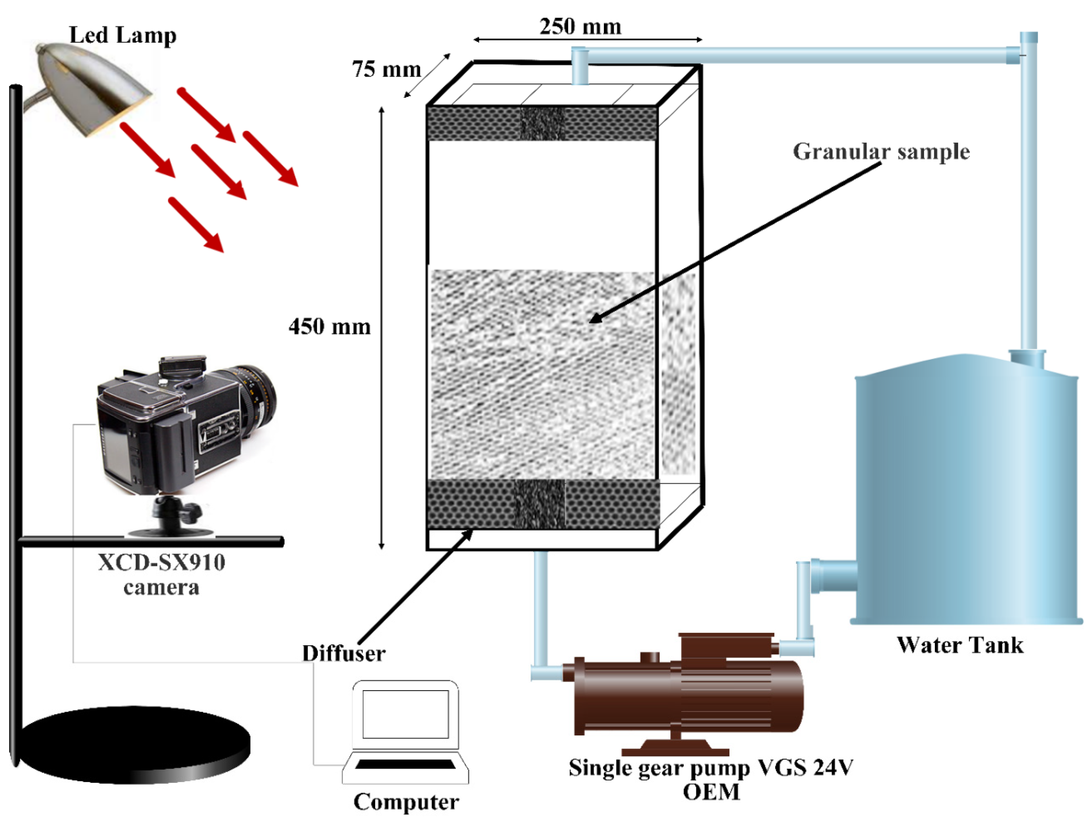
2.1. Experimental Device

The experimental device (Figure 1) constituted a parallelepipedic cell with a section of 450 × 75 × 250 mm with transparent and non-deformable walls. The cell was provided with feed and discharge orifices located at the ends of the cell. The fluid circulated in a closed loop via a pump, immersed in a reservoir, and which generated a constant flow rate in the cell. To homogenize the flow, diffusers were used and placed between the feed orifices and the granular sample. A flowmeter was used to measure the flow rate and an overflow system at the outlet ensured a constant level of liquid in the cell. A fast camera, attached to an adjustable tripod, was placed in front of the device. It was equipped with a lens to visualize and film the entire granular sample during each experiment. To have sufficient contrast, the cell was illuminated by projectors.

2.2. Experimental Procedure

Siliceous sand with a density of 2500 kg·m−3 and sieved to a range of 1.410−3–1.610−3 m constituted the granular sample for the experimental procedure. After the introduction of a mass of dry sand into the cell, a homogeneous fluidization of the stack was generated to obtain a flat surface at the interface. The starting state, reproducible, was then obtained when the particles sedimented and formed an almost flat bed. The denser granular sample was obtained by shaking the box and by administrating small hammer strokes. The empty spaces between the grains were then reduced and the density of the stack was thus raised.

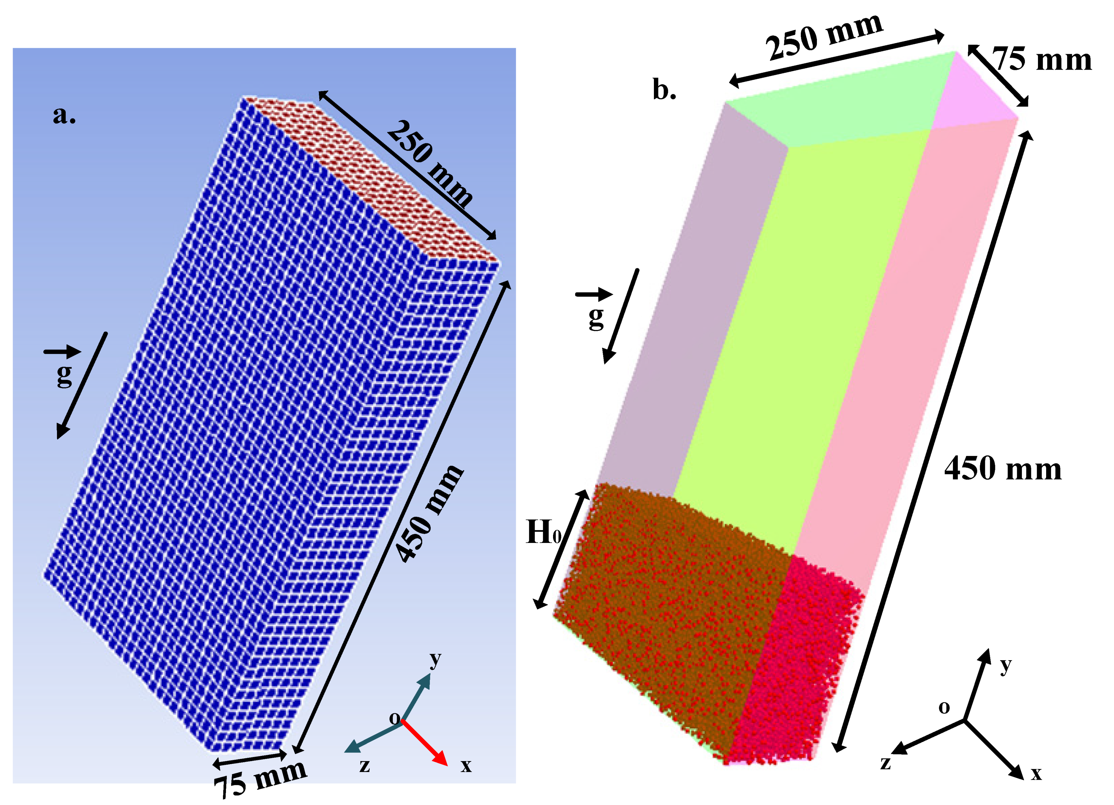
3. Numerical Model and Method

3.1. Numerical Model

Most previous studies of the behavior of a fluid–solid fluidized bed used a two-dimensional coupling model, most of the time between the DEM method and the lattice Boltzmann method (LBM) [4,19,20,21].
Two-dimensional models did not give a very clear account of the mechanical and hydraulic properties involved in the study of the behavior of a granular bed subjected to a localized upward flow. To realistically give account for these granular behaviors and for a quantitative approach to this problem, we developed a three-dimensional model in this work, based on the coupling of two particulate methods, EDEM and ANSYS-FLUENT. EDEM, used for describing solid particle dynamics, is a commercial software of discrete element method (DEM) expanded for taking into account the bulk material simulation. The continuous model, based on the Eulerian multiphase models code in CFD-FLUENT, is used for solving the fluid dynamics equation. Figure 2 provides an overview of EDEM-FLUENT coupling process flow.
The present study, which concerns the case of dense granular materials immersed, takes into account the approach of deformable bodies in contact. This approach allows for multiple particle interactions (including possible local deformation at the point of contact that is frequent in dense fluidized beds).
Particle movement is tracked individually according to Newton’s motion laws:
m p d u p d t = F P + F D + F C
I p d ω p d t = T p
where m p is the particle mass, u p is the particle velocity, F P is the particle gravity force, F D is the fluid–particle drag force, F C is the contact force, ω p is the particle angular velocity, I p is the particle inertia momentum, T p is the applied resulting torque on the particle.
The drag force represents the energy dissipation resulting from the effects of the fluid on the particles during the movement. It is expressed by:
F D = β V p ( 1 ε )   ( u f u p )
where V p is the volume of particle, β is the interphase transfer term, ε is the porosity.
The particle gravity force is expressed by:
F P = m p   g = V p ( ρ p ρ f ) g
The soft sphere model, proposed by Cundal and Strack [22] and used for the first time by Tsuji et al. [23], was adopted in this study to solve all the problems of particle deformation and collision of each particle. Forces are studied as the three models (spring, dashpots and a slider).These particle–particle and particle–wall contact forces are calculated as a function of spring constants and damping coefficients. The following enumerated equations are used to account for particle overlaps in the model of soft spheres during particle collisions:
F C i = j ( f n , i j + f t , i j )
T p i = j ( r i n i j × f t , i j )
In which F C i is the net contact force acting on a particle i because of its neighbors, T p i is the couple acting on a particle i because of its neighbors, f n , i j and f t , i j are the normal and tangential forces on particle i by particle j.
f n , i j = κ n δ n , i j σ n v n , i j
and
f t , i j = κ t δ t , i j σ t v t , i j
where δ n , i j and δ t , i j express the normal and tangential interpenetration of the two particles i and j, κ n   , κ t are respectively the stiffness at normal and tangential contact, σ n ,   σ t are respectively the normal and tangential viscous damping coefficient and where normal and tangential relative velocities v n , i j and v t , i j are given by the relations:
v n , i j = d δ n , i j d t = ( v i v j ) · n i j
v t , i j = d δ t , i j d t = ( v i v j ) v n , i j + ( r i ω i + r j ω j ) · n i j
The friction slider limits the tangential force governed by Coulomb’s friction law [24].
| f t , i j | ξ | f n , i j |
Water phase is modeled in CFD-FLUENT as a continuous fluid phase. The equations of continuity and momentum conservation are solved for each time step related to the fluid phase:
The continuum equation for the q phase is:
( ε q ρ q ) t + · ( ε q ρ q u q ) = 0
The momentum balance for the q phase is:
( ε q ρ q u q ) t + · ( ε q ρ q u q u q ) = · P + · τ ¯ q + ε q ρ q g k s l ( u p u q )
In which expressions, ρ q is the q phase density, g is the acceleration of gravity, u p and u q are the phase velocities, τ ¯ q is the q phase stress–strain tensor given by:
τ ¯ q = μ q ( u q , i x j + u q , j x i ) + ( λ q 2 3 μ q ) · u q
Here, μ q and λ q are the q phase’s shear and bulk viscosity.
k s l is the interphase momentum exchange coefficient. For granular flows, momentum exchange between phases is based on the fluid–solid exchange coefficients value. In CFD-ANSYS Fluent, the interphase exchange coefficient models are empirically based. The Gidaspow model, which is a combination of the Wen and Yu model [25] and the Ergun equation [26], is used in this study. This model is recommended for dense fluidized beds.
k s l = { 3 4 C D ε s ε l ρ l | u s u l | d s ε l 265 ; ε l > 0.8 150 ε s ( 1 ε l ) μ l ε l d s 2 + 1.75 ρ l ε l | u s u l | d s   ; ε l 0.8 }
where μ l is the water dynamic viscosity, d s is the particle diameter and C D is drag force coefficient of a single particle. C D is expressed by:
C D = 24 ε l R e s [ 1 + 0.15 ( ε l R e s ) 0.687 ]
With the Reynolds number as:
R e s = ε l ρ l d s | u s u l | μ l
More detailed information on the Gidaspow model can be found in Reference [27].

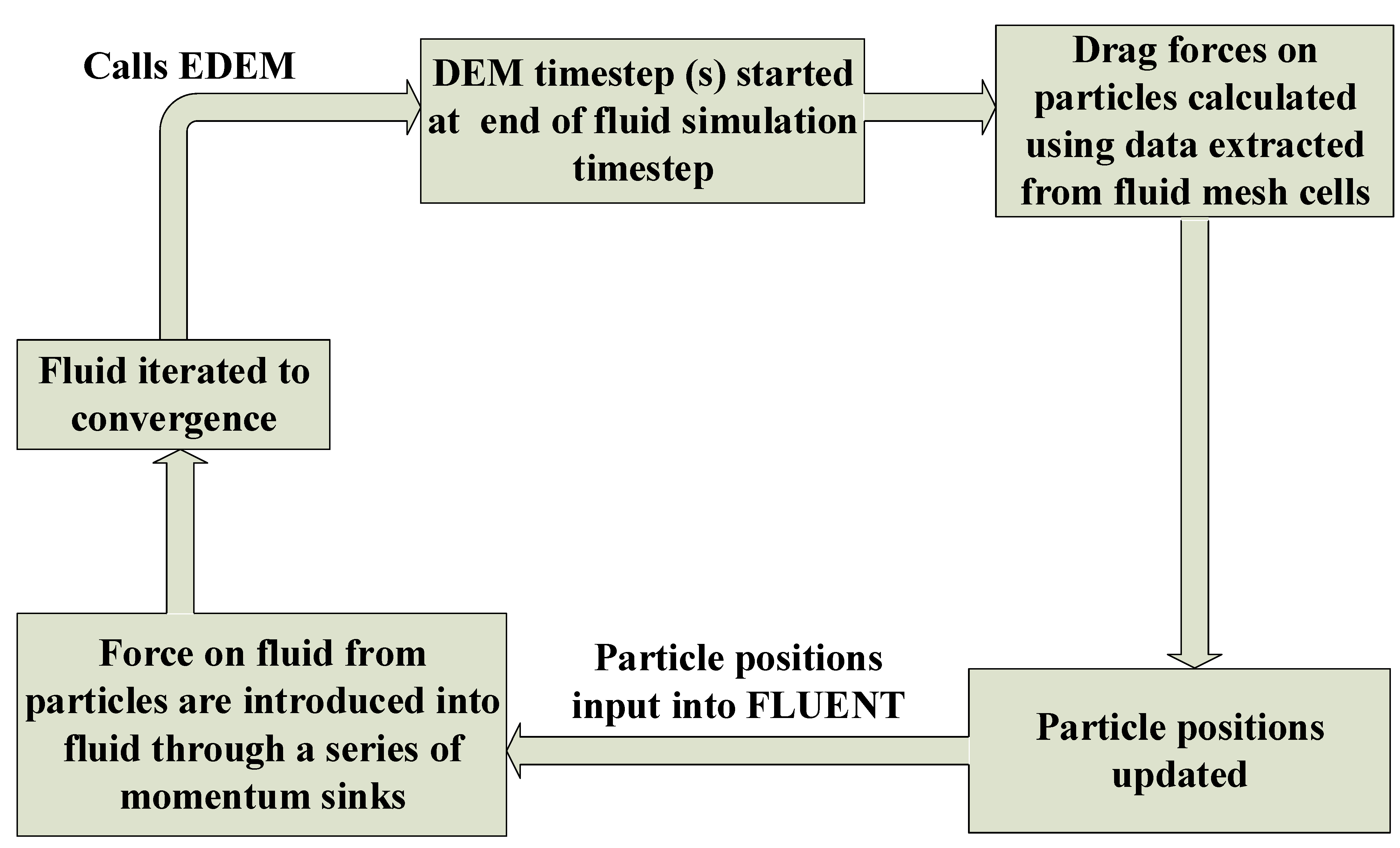
3.2. EDEM-CFD FLUENT Coupling Details

The fluid phase is, at the start, analyzed by ANSYS-FLUENT using the solutions of the Navier–Stokes equation and the standard k-epsilon turbulence model. For a given time step, iteration of the simulation is performed in Fluent until convergence is reached.
Then, EDEM calculates body forces acting on each particle (gravity, fluid drag, electrostatic) using data extracted from fluid mesh cells, and eventually determines updated particle position, acceleration and velocity. These different coordinates of the particles thus updated are transferred to the CFD solver ANSYS-FLUENT and the forces exerted on the fluid by the particles are introduced into the fluid through a series of momentum source terms.
In the EDEM-CFD FLUENT coupling, EDEM replaces the solid phase approximation in FLUENT with an explicit computation of particle dynamics in EDEM.
In this study, the Gidaspow model, which is a combination of the Wen and Yu model and the Ergun equation, was used. Moreover, the soft sphere model was adopted to solve all the problems of particle deformation and collision of each particle. In every time step the result from EDEM was transferred to FLUENT and there, the equations of continuity and momentum conservation were solved for each time step. To avoid a large solids kinetic energy dissipation at the wall region and to avoid allowing some particles to stay in the wall region, a fixed restitution and friction coefficients were chosen (Table 1).

3.3. Materials and Simulation Procedures

The simulations were carried out on a granular of silicon-si (sand) assembly which constituted the discrete phase provided by EDEM whereas the liquid water of kinematic viscosity νf = 2.0 × 10⁻⁶ m2·s−1, provided by FLUENT database by setting up the materials and operating conditions in Fluent, constituted the continuous phase. The particles of spherical form had a density of 2500 kg·m−3 and an average size of 1.610−3 m while the density of the water was 1000 kg·m−3. The initial volume fractions of the particles were fixed at 0.52 and 0.62. The size of the maximum injection dimax was taken as practically equal to the width L of the grain layer (dimax ≈ L ≈ 250 mm). It is reported that hydrodynamics mechanisms are very sensitive to a change of restitution and friction coefficients [28]. Moreover, some low values of restitution coefficient can lead to a large solids kinetic energy dissipation at the wall region and allow some particles to stay in the wall region [29]. With the fixed simulation parameters in Table 1, the different observations made during the experimental phase were realistically reported.
For the simulation, we imposed a flow velocity U greater than the fluidization threshold, at the base of the granular layer, and kept constant during the duration of the simulation.

3.4. Simulation Domain and Meshing

The computation was conducted in three-dimensional domain constituted of a parallelepipedic cell with 250 × 75 × 450 mm as dimensions. The integrated computer engineering and manufacturing (ICEM) code was used to mesh the computational domain (Figure 3a). A total of 7875 finer hexahedral cells with 9568 nodes constituted the entire computational domain. Moreover, the acceleration of the gravity (g = 9.81 m·s−2) was taken into account and its direction was evaluated as being opposite to the flow direction penetrating the domain entrance.

3.5. Image Processing

To measure the height of the fluidized zone Hf and the total height at the injection zone H, image processing was performed with the National Institute of Health’s ImageJ software. This processing and analysis software allows one to ascertain the granular layer height measurements from images.

3.6. Transient Analysis

For this numerical study of destabilization of a sand granular stack immersed by homogeneous fluidization, a three-dimensional model coupling the discrete element method (EDEM) to describe the mechanical behavior of the particle assembly and the CFD-ANSYS-FLUENT method to render account of the hydrodynamics of the interstitial fluid, has been developed. The granular samples used consisted of stacks of silicon grains in a rectangular parallelepipedic cell. After sedimentation of particles, stable stacks were obtained under gravity. The two granular samples were prepared, in EDEM, with an initial H0 stacking height of 115 mm but with starting volume fractions of 0.62 and 0.52 (Figure 3b). The grains, in a uniform particle size distribution, had an average diameter of 1.6 mm. At the base of the cell, an injection speed U was imposed and kept constant during each simulation. The simulations were planned to study the situation where the stresses exerted by a liquid flowing through an immersed granular medium were sufficient, alone, to set in motion certain grains and fluidize a whole part of the stack. The authors have studied the application of the commercial DEM software (EDEM) coupled with the CFD-ANSYS Fluent software on the fluidized bed system, including the validation of this model. However, the results, compared to experimental measurements obtained from the literature, qualitatively capture the physics of fluidization [30]. In addition, it is shown that generally, with a finer grid, all iterative solution methods converge with good accuracy. The computation may require significantly more time [31]. In total, 7875 finer hexahedral cells constituted the computational domain in this work. Moreover, to capture the particles’ behavior accurately, a smaller integration time step was also essential. Thus, the time step of 10−4 s was chosen in this work, which is certainly supposed to be small enough to produce reasonably accurate results. The validation of this numerical model is also based on the visual observations of dynamic process during the experimental work.

4. Results and Discussions

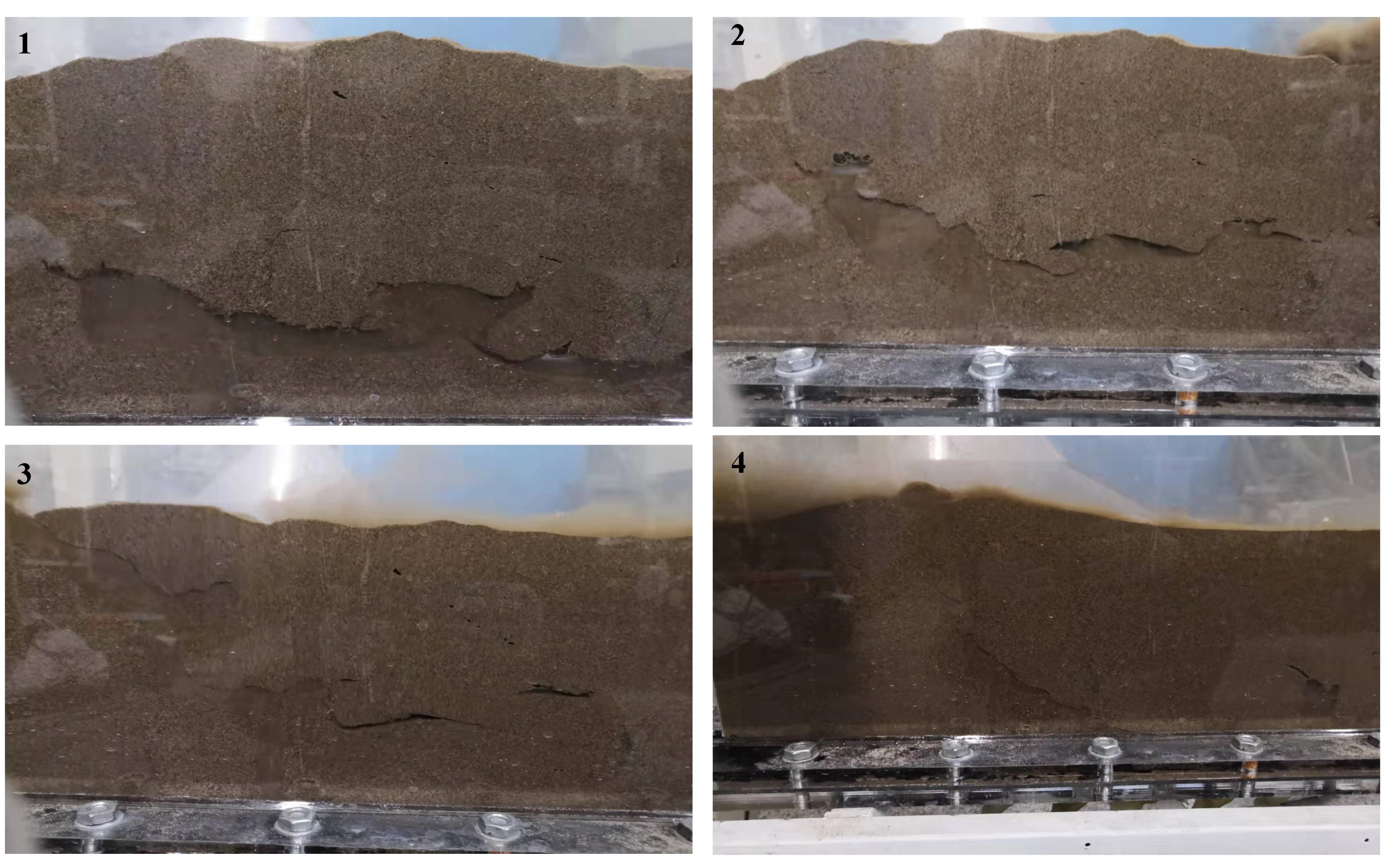
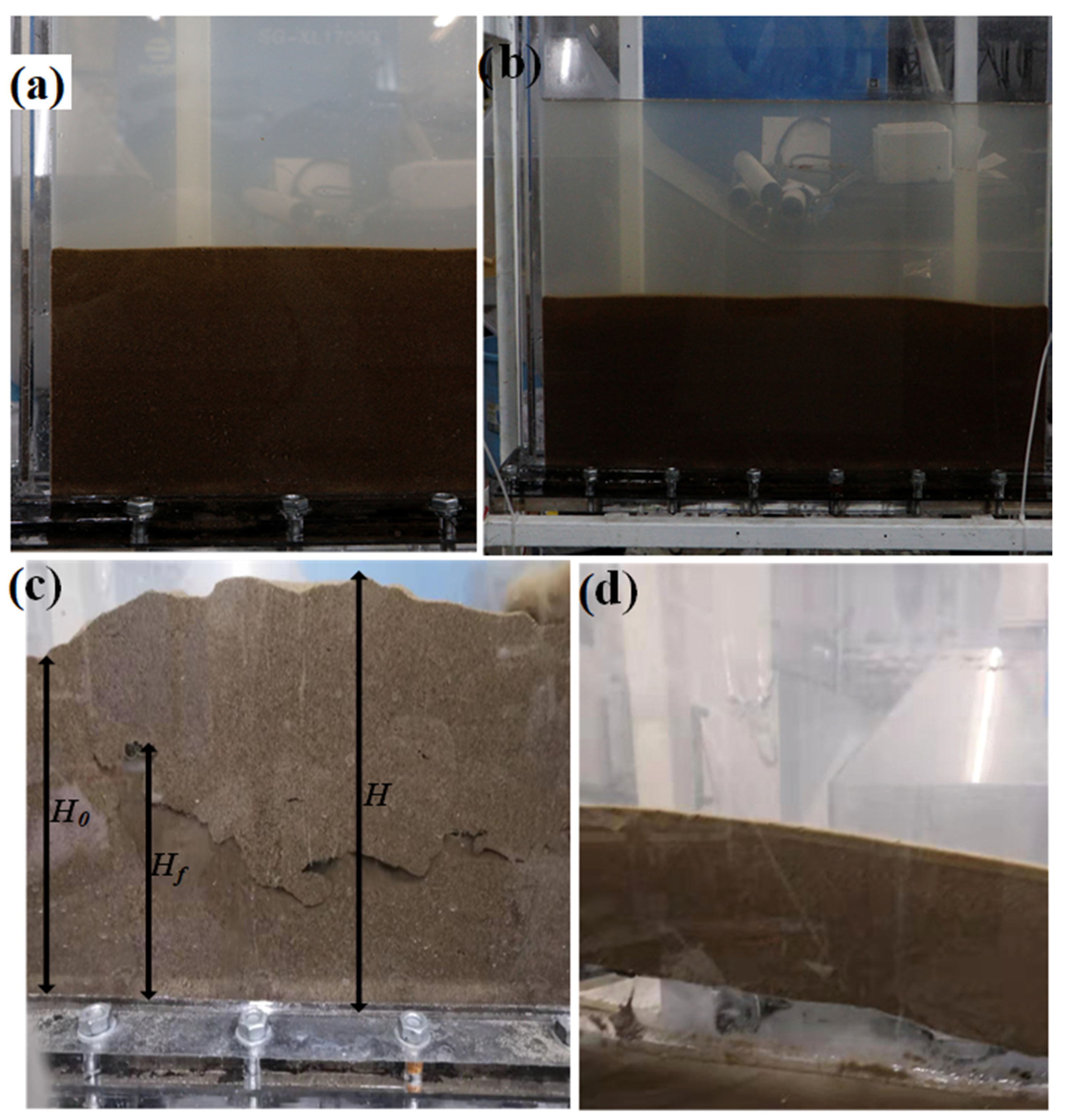
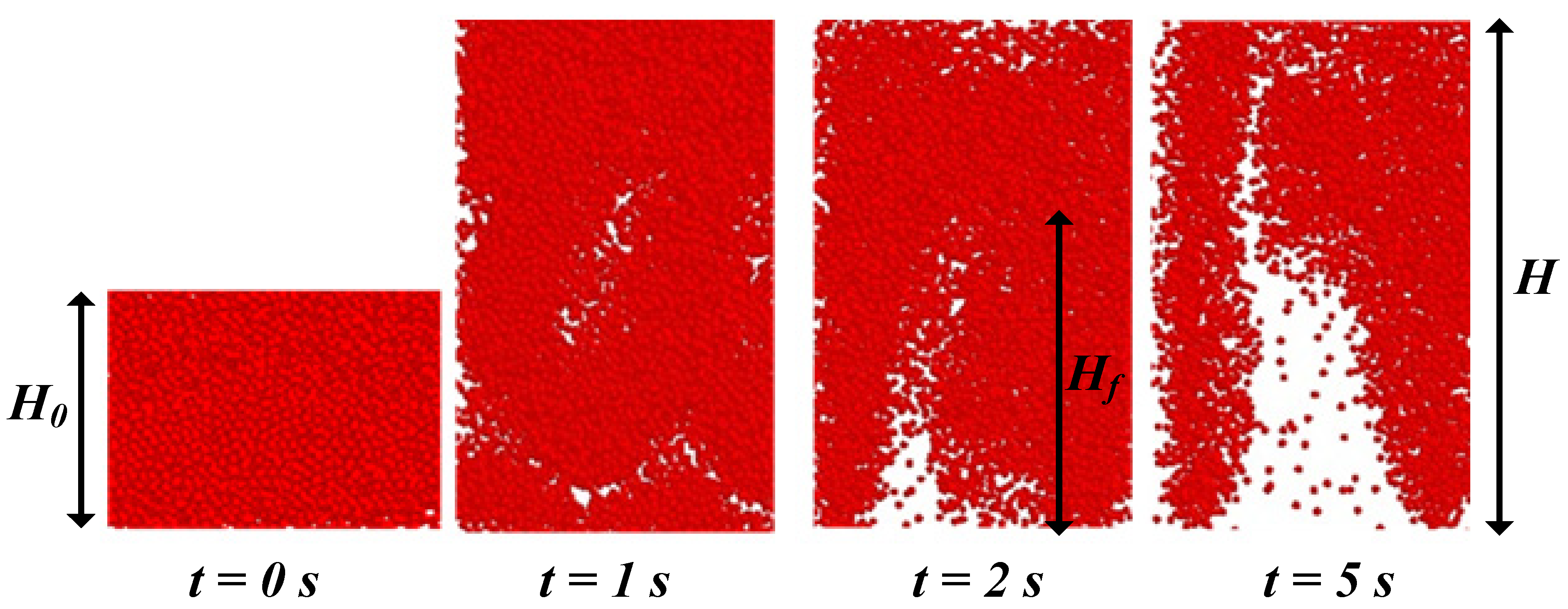
4.1. Experimental Observation

The study of the growth dynamics of the fluidized zone revealed different grain dynamics depending on the initial density of the material (Figure 4):
  • The loose stack fluidized quickly in a turbulent and chaotic manner from the injection zone to the top of the granular layer, with regular expansion of the entire stack.
  • The dense stack was destabilized in a different way. An upward movement of the assembly without deformation in the material was observed. Moreover, the lower surface was gradually destabilized, thus releasing a shower of grains that gradually supplied the fluidized zone. The size of the ascending grain layer in solid translation motion decreased regularly while the fluidized layer increased.
The dilating character of the sand volume seems to be at the basis of the observed phenomenon. Indeed, an imbalance of the contact forces induced by the flow on the grains causes this destabilization phenomenon, when these induced forces are more significant than the apparent weight of the granular stack. With an initially loose medium, there can be fluidization with large relative movements of grains in the interior and a more or less regular expansion of the whole material (Figure 5). In contrast, if the medium is initially dense enough, it can maintain a solid body behavior and thus take off vertically. In order to fluidize the material in the dense case, the grains first should be disentangled in the granular stack. This involves increasing the volume of the material in the box. Moreover, the box, by its rigid side walls, imposes a geometric confinement to the material. Hence, the observation of the vertical takeoff of the material in the dense case.

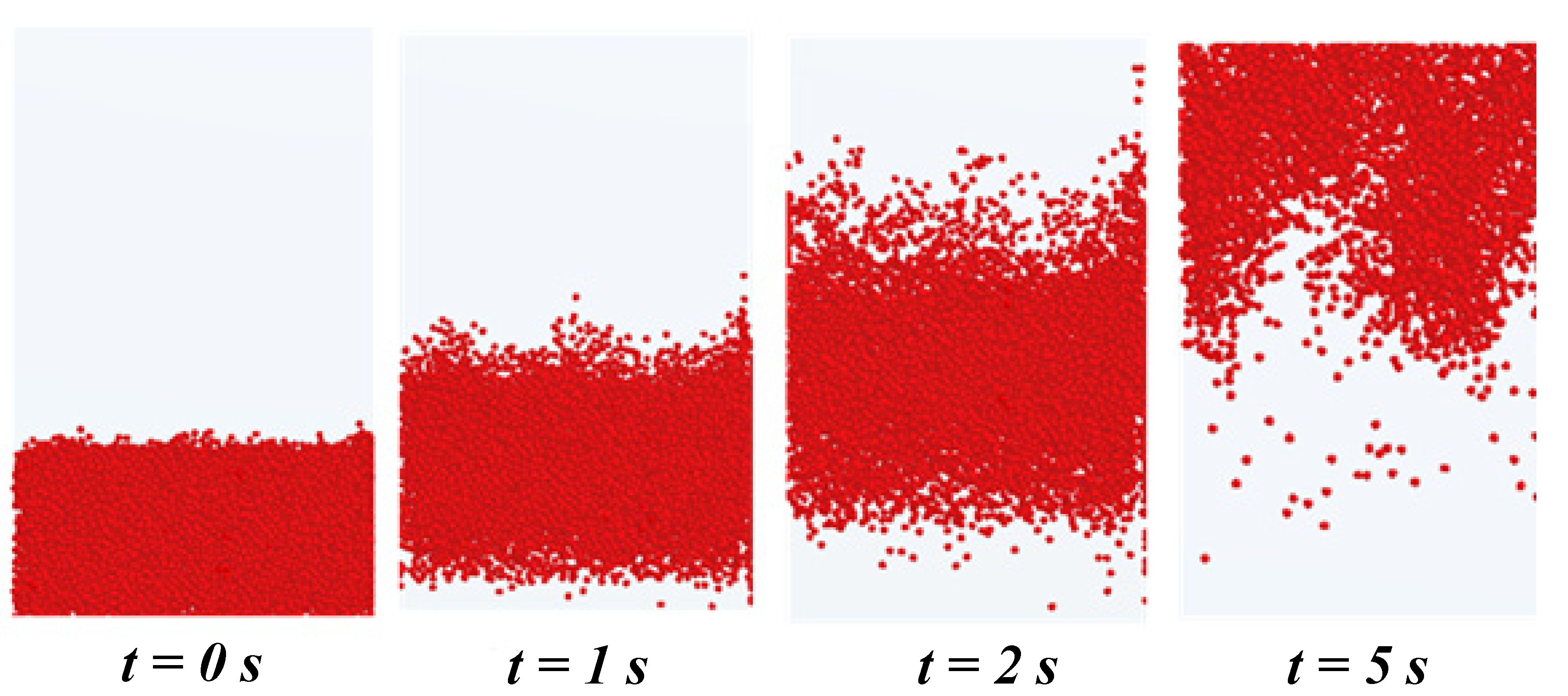
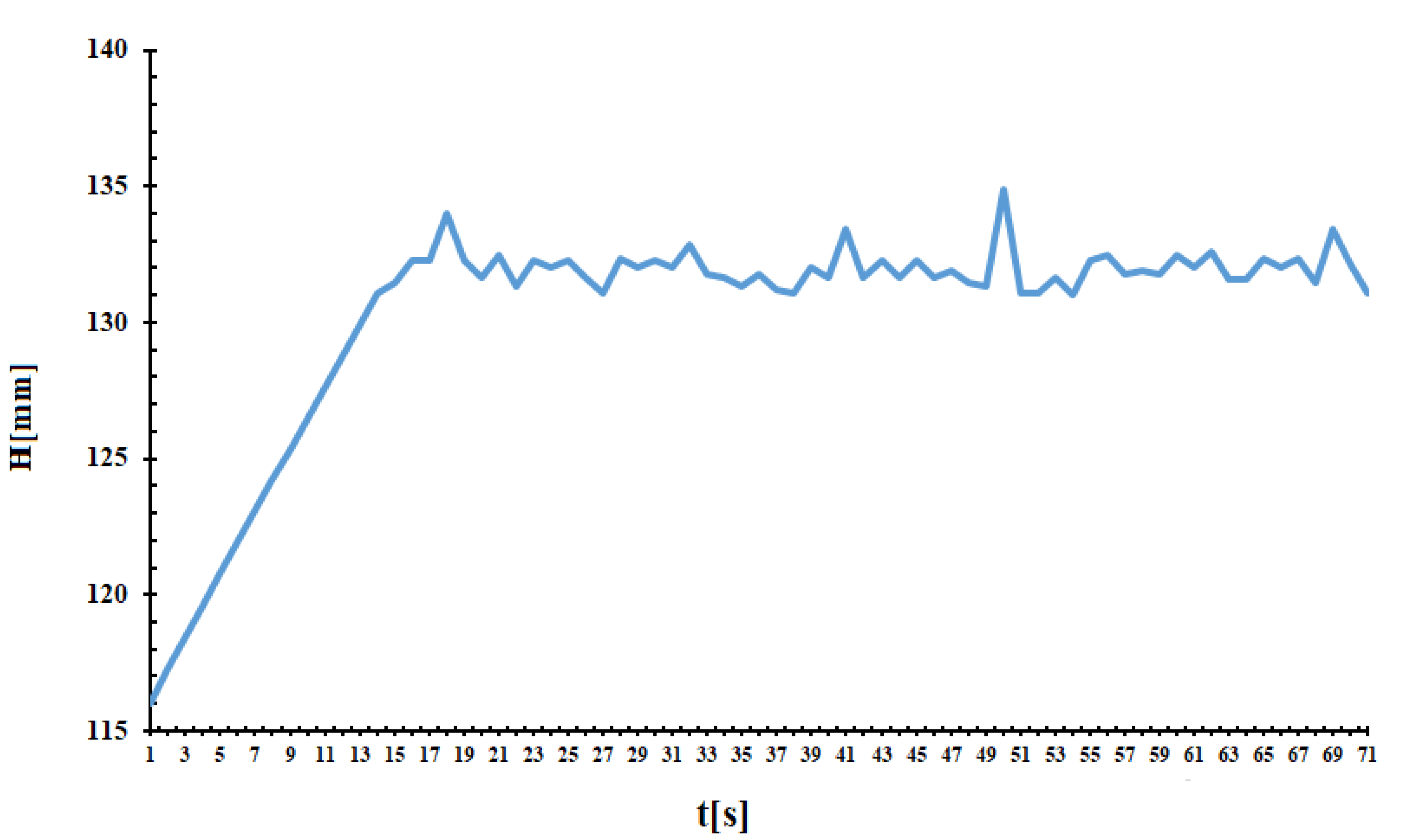
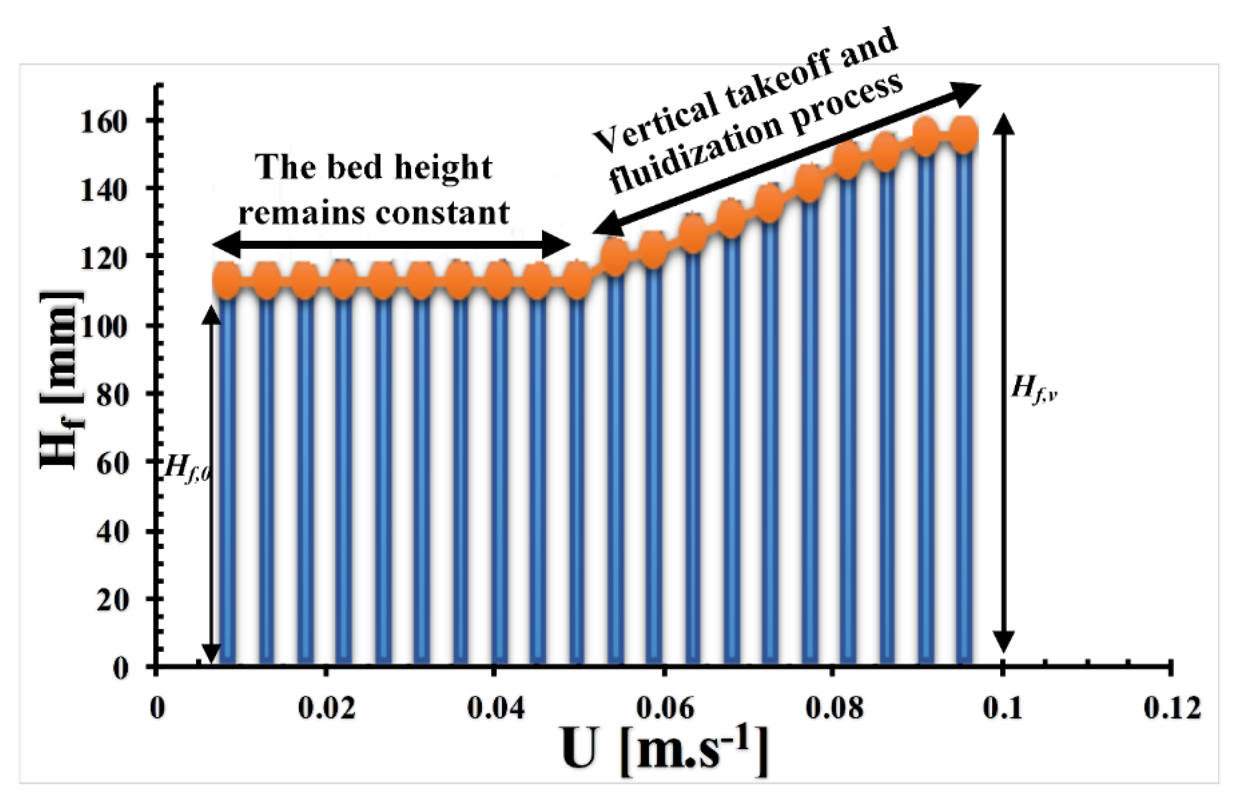
4.2. Numerical Results and Discussions

Figure 6 and Figure 7 illustrate the growth dynamics of the fluidized zone of the immersed granular stack. As we can see, there are different grain dynamics depending on the initial density of the material. The loose stack rapidly fluidized from the injection zone to the top of the granular layer in a turbulent manner with a uniform overall expansion.
Conversely, for the same material in a dense state, there was a mass takeoff of the stack, which added to the propagation of an instability of the wavy porosity type from bottom to top of the stack with fast kinetics, which decompacted the medium.
CFD and EDEM (two particulate methods) were coupled to carry out a numerical study of the destabilization mechanism observed during the previous experimental study of the destabilization of an immersed granular material by homogeneous fluidization. According to the results, the same destabilization scenario of the immersed granular material was observed. A marked difference in behavior during the transient regime has been highlighted: a loose stack fluidizes from the injection zone to the top of the granular layer while for the same material in a dense state, there is a takeoff of the material without deformation. This mechanism of destabilization, which led to a fluidization of the medium in the loose state case, could be explained by the imbalance between the contact forces induced by the flow on the grains and the apparent weight of the granular stack. On the other hand, the effect of the resultant forces and the confinement imposed by the side walls can give a solid body behavior to the granular stack in the dense case and cause a vertical takeoff of the material.
The numerical and experimental studies have noted that for the loose granular stack, porosity wave instability propagates from the base to the top. Then, there begins a bed expansion process with eruptions on the surface. Moreover, by observing the behavior of the bed during the experimental phase, it is clear that the numerical observations show good agreement with the experimental observations. However, other more in-depth studies devoted to these numerical and experimental observations are in progress and will be the subject of further submissions in the near future.
However, we have represented, in Figure 8, the fluidized bed height evolution as a function of the time for a fluidization rate of U = 0.07 m·s−1. It is important to mention that the fluidized bed height increased linearly with the time until reaching a state where its variation remained almost stationary.
Retrieved data from image sequences also allowed us to plot, in Figure 9, the variation of the maximum fluidized bed height Hf as a function of the fluidization rate U. Indeed, in the case of dense granular stack, we have, at the very beginning of the fluidization process, a fixed bed regime where the height of the bed varies only when the velocity reaches a given value (U = 0.07 m·s−1). This corresponds well to the phenomenon observed during the homogeneous fluidization process of a dense granular stack where, in order to fluidize the material, the grains must first be disentangled in the granular stack. They retain a solid body behavior in a first phase. Subsequently we attend, because of the imposed geometric confinement by the walls, to the vertical takeoff of the material and the fluidization of the bed during which the height of the bed increases progressively with the flow rate. It should also be noted that the higher the flow rate increases, the fluctuations of the height of the bed become very important.

5. Conclusions

The present study is part of the framework of the study of the destabilization of a granular stack immersed by fluidization. It highlighted the significant influence of the initial density (initial volume fraction) of the granular stack on the transient homogeneous fluidization regime. It was intended as a contribution to the research perspective that aims to better understand fluid–grain coupling and its role in the development of hydromechanical instabilities. Indeed, the results revealed two different types of dynamics in the way the medium deformed under the action of an upward and homogeneous flow. For an initially loose stack, a homogeneous turbulent fluidization was observed, whereas for an initially dense stack, there was a mass takeoff of the stack, which was added to the propagation of wave porosity type instability from the bottom to the top of the stack with fast kinetics that decompacted the medium.
Moreover, the numerical results from the study of the transient homogeneous fluidization regime of an immersed granular medium were rather in general qualitative agreement with the experimental results. These results also revealed an original observation of the very strong impact of the initial density of an initially static granular stack on the transient fluidization regime. It would be very interesting to consider a more systematic approach to the impact of geometric confinement on the rate of expansion of the porosity wave. The interest here is to limit or even stop the desired fluidization by the hydrodynamic constraints.

Author Contributions

Conceptualization, A.S.D., L.W.; methodology, A.S.D., L.W.; software, A.S.D.; validation, A.S.D., L.W.; formal analysis, A.S.D., L.W.; investigation, A.S.D., L.W.; resources, L.W.; data curation, A.S.D., L.W.; writing-original draft preparation, A.S.D.; writing-review and editing, A.S.D., L.W., Y.Z.; supervision, L.W., Y.Z.; project administration, L.W., Y.Z.; funding acquisition, L.W., Y.Z. All authors have read and agreed to the published version of the manuscript.

Funding

The National Key R&D Program of China (Grant No. 2016YFB0601101) and the Open Fund Project for State Key Laboratory of Iron and Steel Industry Environmental Protection (No. 2016YZC04) supported this work. This research was supported by The National Key R&D Program of China, Grant No. 2016YFB0601101 and the Open Fund Project for State Key Laboratory of Iron and Steel Industry Environmental Protection Grant No. 2016YZC04. The APC was funded by authors.

Institutional Review Board Statement

Not applicable.

Informed Consent Statement

Not applicable.

Data Availability Statement

Not applicable.

Conflicts of Interest

The authors declare no conflict of interest.

References

  1. Yates, J.G.; Lettieri, P. Fluidized-Bed Reactors: Processes and Operating Conditions; Springer: Berlin/Heidelberg, Germany, 2016. [Google Scholar]
  2. Rhodes, M.J. Introduction to Particle Technology; John Wiley: Chichester, UK; New York, NY, USA, 1998. [Google Scholar]
  3. Montell, E.P.; Toraldo, M.; Chareyre, B.; Sibille, L. Localized fluidization in granular materials: Theoretical and numerical study. Phys. Rev. 2016, 94, 52905. [Google Scholar] [CrossRef] [Green Version]
  4. Cui, X.; Li, J.; Chan, A.; Chapman, D. A 2D DEM-LBM study on soil behaviour due to locally injected fluid. Particuology 2012, 10, 242–252. [Google Scholar] [CrossRef]
  5. Philippe, P.; Badiane, M. Localized fluidization in a granular medium. Am. Phys. Soc. 2013, 87, 42206. [Google Scholar] [CrossRef] [PubMed]
  6. Zoueshtiagh, F.; Merlen, A. Effect of a vertically flowing water jet underneath a granular bed. Am. Phys. Soc. 2007, 75, 056313. [Google Scholar] [CrossRef]
  7. Philippe, P.; Mena, S.; Brunier-coulin, F.; Curtis, J. An experimental study of the transient regime to fluidized chimney in a gran-ular medium. Powders Grains 2017, 140, 09030. [Google Scholar]
  8. Philippe, P.; Cuéllar, P.; Luu, L.; Mena, S.; Curtis, J.S. Localized fluidization in a granular medium: Parametric study with a physical model of ‘sand boiling’. In Scour and Erosion: Proceedings of the 8th International Conference on Scour and Erosion (Oxford, UK, 12–15 September 2016); CRC Press: Boca Raton, FL, USA, 12–15 September 2016; p. 7, ⟨hal-02605288⟩. [Google Scholar]
  9. Alsaydalani, M.O.A.; Clayton, C.R.I. Internal Fluidization in Granular Soils. J. Geotech. Geoenviron. Eng. 2014, 140, 4013024. [Google Scholar] [CrossRef]
  10. Perry, R.H.; Green, D.W.; Maloney, J.O. Perry’s Chemical Engineers’ Handbook, 7th ed.; McGraw-Hill: New York, NY, USA, 1997. [Google Scholar]
  11. van Buijtenen, M.S.; van Dijk, W.J.; Deen, N.G.; Kuipers, J.A.M.; Leadbeater, T.; Parker, D.J. Numerical and experimental study on multiple-spout fluidized beds. Chem. Eng. Sci. 2011, 66, 2368–2376. [Google Scholar] [CrossRef]
  12. MacDonald, J.F.; Bridgwater, J. Void formation in stationary and moving beds. Chem. Eng. Sci. 1997, 52, 677–691. [Google Scholar] [CrossRef]
  13. Agarwal, G.; Lattimer, B.; Ekkad, S.; Vandsburger, U. Influence of multiple gas inlet jets on fluidized bed hydrodynamics using Particle Image Velocimetry and Digital Image Analysis. Powder Technol. 2011, 214, 122–134. [Google Scholar] [CrossRef]
  14. Hong, R.Y.; Guo, Q.J.; Luo, G.H.; Zhang, J.Y.; Ding, J. On the jet penetration height in fluidized beds with two vertical jets. Powder Technol. 2003, 133, 216–227. [Google Scholar] [CrossRef]
  15. Merry, J.M.D. Penetration of vertical jets into fluidized beds. AIChE J. 1975, 21, 507–510. [Google Scholar] [CrossRef]
  16. Bonelli, S. Erosion in Geomechanics Applied to Dams and Levees; Wiley: Hoboken, NJ, USA, 2013. [Google Scholar]
  17. Chetti, A.; Benamar, A.; Hazzab, A. Modeling of Particle Migration in Porous Media: Application to Soil Suffusion. Transp. Porous Media 2016, 113, 591–606. [Google Scholar] [CrossRef]
  18. Suzuki, K.; Bardet, J.-P.; Oda, M.; Iwashita, K.; Tsuji, Y.; Tanaka, T.; Kawaguchi, T. Simulation of Upward Seepage Flow in a Single Column of Spheres Using Discrete-Element Method with Fluid-Particle Interaction. J. Geotech. Geoenviron. Eng. 2007, 133, 104–109. [Google Scholar] [CrossRef]
  19. Cui, X. Numerical Simulation of Internal Fluidization and Cavity Evolution Due to a Leaking Pipe Using the Coupled DEM-LBM Technique; University of Birmingham Research Archive e-theses repository; University of Birmingham: Birmingham, UK, 2012. [Google Scholar]
  20. Cui, X.; Li, J.; Chan, A.; Chapman, D. Coupled DEM-LBM simulation of internal fluidisation induced by a leaking pipe. Powder Technol. 2014, 254, 299–306. [Google Scholar] [CrossRef]
  21. Chen, S.; Doolen, G. Lattice Boltzmann Method for Fluid Flows. Annu. Rev. Fluid Mech. 1998, 30, 329–364. [Google Scholar] [CrossRef] [Green Version]
  22. Cundall, P.A.; Strack, D.L. A discrete numerical model for granular assemblies. Geotechnique 1979, 29, 47–65. [Google Scholar] [CrossRef]
  23. Tsuji, Y.; Kawaguchi, T.; Tanaka, T. Discrete particle simulation of flow patterns in two-discrete particle simulation of two-dimensional fluidized bed. Powder Technol. 1993, 77, 79–87. [Google Scholar] [CrossRef]
  24. Di Renzo, A.; Di Maio, P.F. Comparison of contact-force models for the simulation of collisions in DEM-based granular ow codes. Chem. Eng. Sci. 2004, 59, 525–541. [Google Scholar] [CrossRef]
  25. Wen, C.Y.; Yu, Y.H. Mechanics of Fluidization. Chem. Eng. Prog. Symp. Ser. 1966, 62, 100–111. [Google Scholar]
  26. Ergun, S. Fluid flow through packed columns.pdf. Chem. Eng. Prog. 1952, 48, 89–94. [Google Scholar]
  27. Gidaspow, D.; Bezburuah, R.; Ding, J. Hydrodynamics of Circulating Fluidized Beds, Kinetic Theory Approach. In Fluidization VII, Proceedings of the 7th Engineering Foundation Conference on Fluidization, Brisbane, Australia, 3–8 May 1992; Engineering Foundation: New York, NY, USA, 1992; Volume 7, pp. 75–82. [Google Scholar]
  28. Sinclair, J.L.; Jackson, R. Gas-Particle Flow in a Vertical Pipe with Particle-Particle Interactions. AIChE J. 1989, 35, 1473–1486. [Google Scholar] [CrossRef]
  29. Cheng, Y.; Zhu, J.-X. CFD Modelling and Simulation of Hydrodynamics in Liquid-Solid Circulating Fluidized Beds. Can. J. Chem. Eng. 2005, 83, 177–185. [Google Scholar] [CrossRef]
  30. Prashant, G. Verification and Validation of a DEM-CFD Model and Multiscale Modeling of Cohesive Fluidization Regimes; The University of Edinburgh: Edinburgh, Scotland, 2015. [Google Scholar]
  31. Alobaid, F.; Epple, B. Improvement, validation and application of CFD/DEM model to dense gas–solid flow in a fluidized bed. Particuology 2013, 11, 514–526. [Google Scholar] [CrossRef]
Figure 1. Schematic representation of the experimental device.
Applsci 11 08696 g001
Figure 2. EDEM-FLUENT coupling process flow.
Applsci 11 08696 g002
Figure 3. Computational domains: (a) ICEM grid; (b) simulation domain with EDEM particles.
Applsci 11 08696 g003
Figure 4. Transitional phases of destabilization: (a) starting sample of loose stack; (b) starting sample of dense stack; (c) turbulent and chaotic fluidization phase for the loose stack; (d) sand takeoff phase for the dense stack.
Applsci 11 08696 g004
Figure 5. Experimental observation of the evolution (from 1 to 4) of the fluidized zone height.
Applsci 11 08696 g005
Figure 6. Transitional phases of destabilization by homogeneous fluidization of an initially loose sand stack.
Applsci 11 08696 g006
Figure 7. Transitional phases of destabilization by homogeneous fluidization of an initially dense sand stack.
Applsci 11 08696 g007
Figure 8. Evolution of the fluidized-sand bed height as a function of time, for a fluidization rate of 0.07 m·s −1. Numerical results obtained with a stack of initial height H0 = 115 mm.
Applsci 11 08696 g008
Figure 9. Evolution of maximum fluidized bed height Hf as a function of the fluidization rate U.
Applsci 11 08696 g009
Table 1. Fluent-EDEM simulation parameters used for the study.
ParametersValuesUnits
Fluid density1000kg/m3
Solid density2500kg/m3
Kinematic viscosity of the fluid2.0 × 10−6m2/s
Coefficient of friction of particle0.5-
Coefficient of restitution of particle0.5-
Grain average diameter1.610−3m
Initial volume fraction of sand0.52–0.62-
Gravity9.81(m/s2)
Duration of simulation10s
Publisher’s Note: MDPI stays neutral with regard to jurisdictional claims in published maps and institutional affiliations.

