
Bearing Capacity and Failure Mode of a Light-Steel Tubular K-joint Connected by a Novel U-shape Connector


 ,
,
Abstract
:1. Introduction
2. Specimen Fabrication
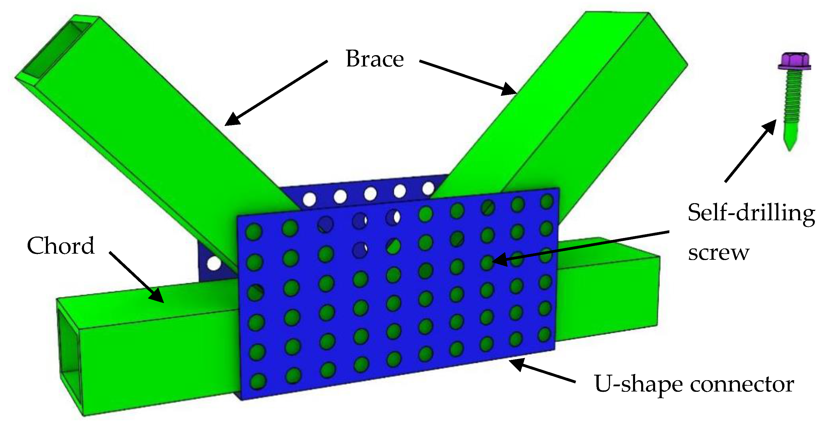
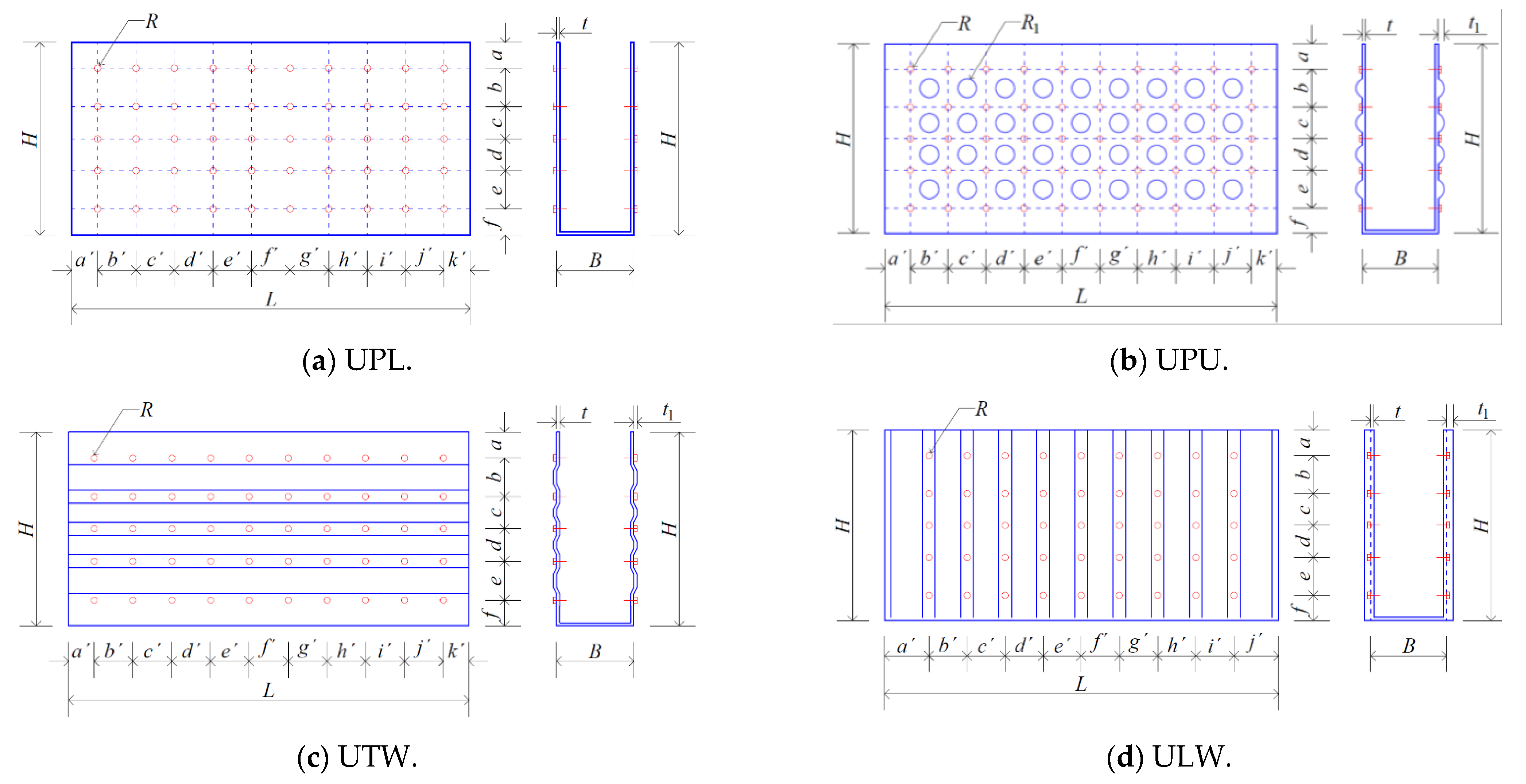
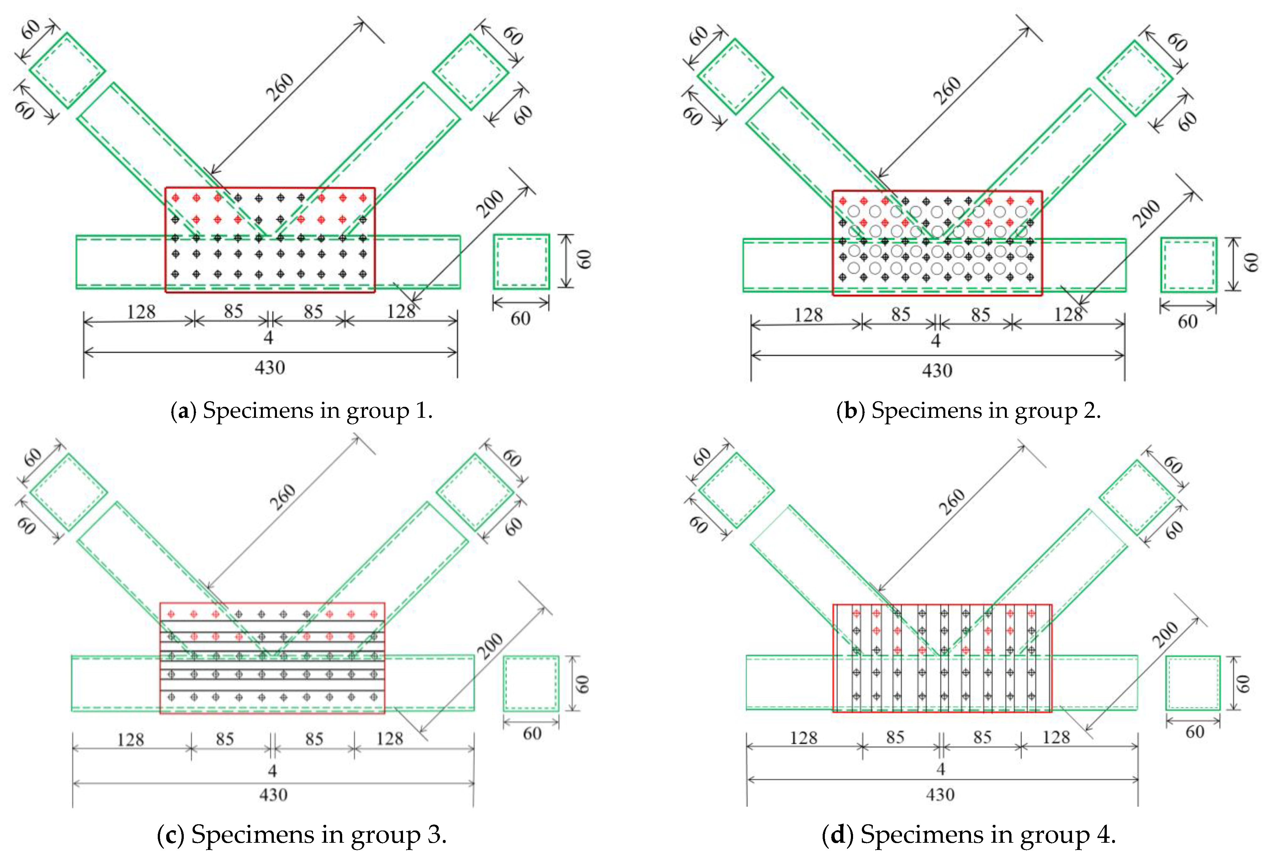
2.1. U-shape Connectors and K-joint Specimens
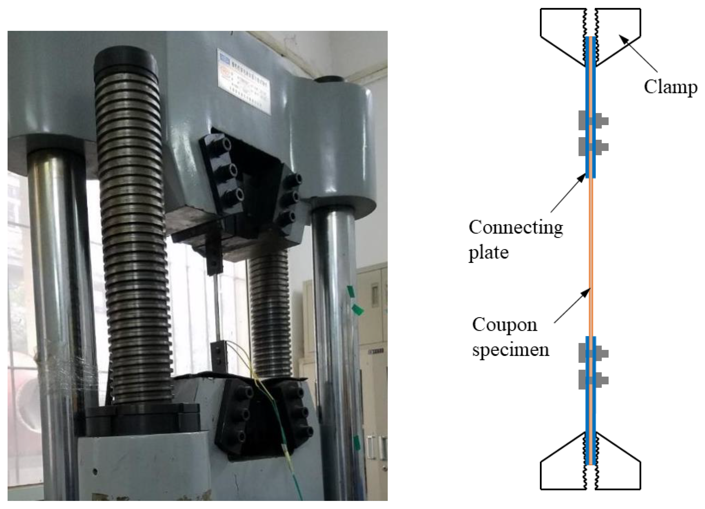
2.2. Material Properties of Steel
3. Testing Rig, Loading Scheme and Displacement Transducer Deployment
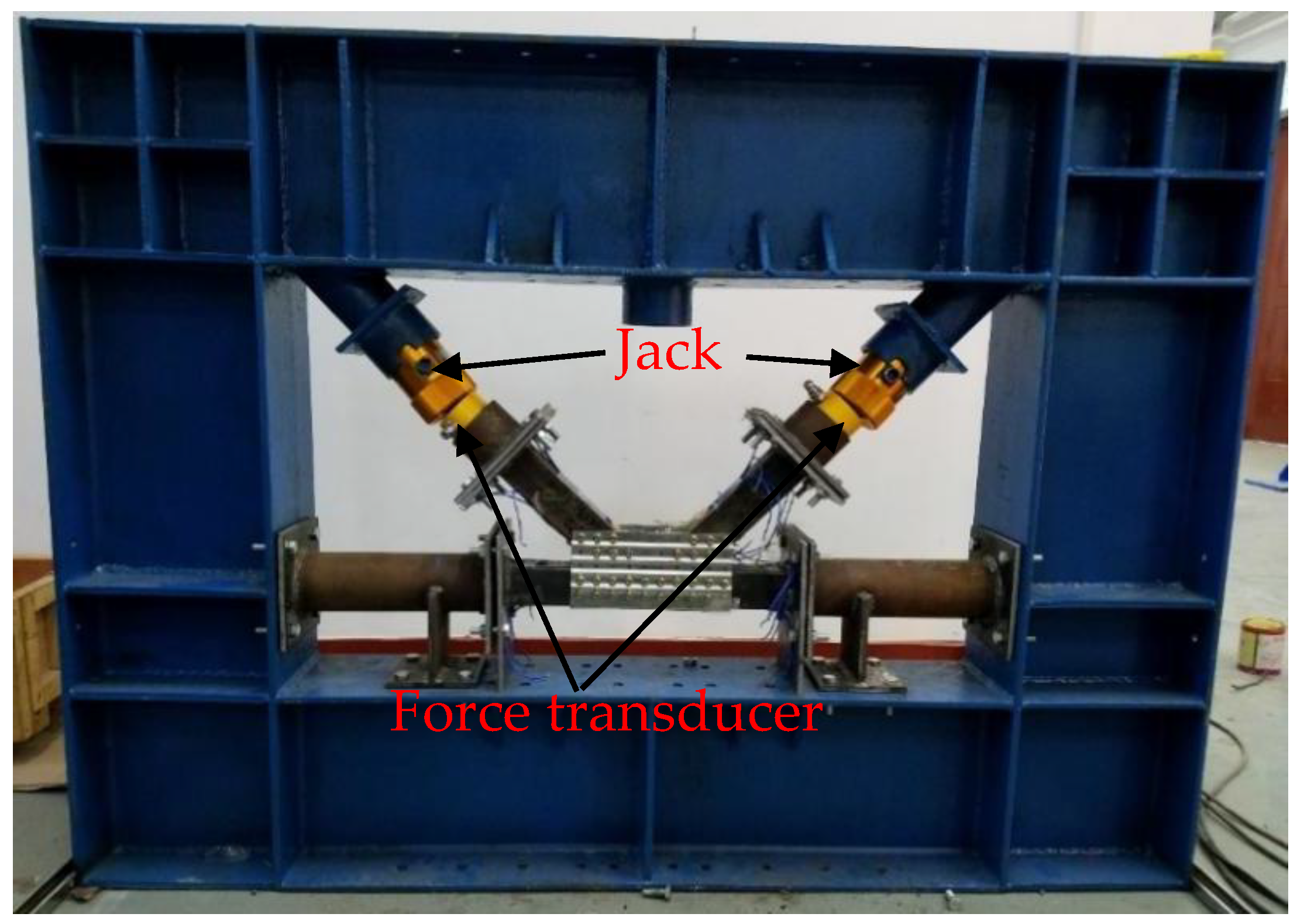
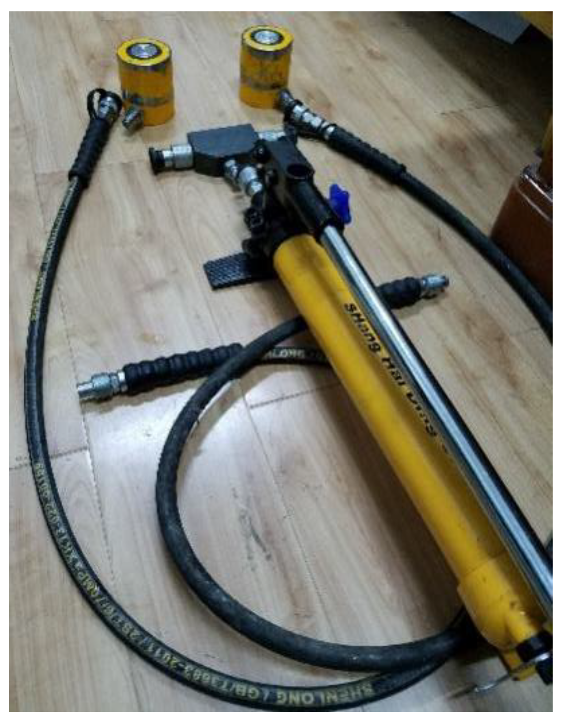
3.1. Testing Rig and Loading Scheme
3.2. Displacement Transducer Deployment
4. Experimental Results
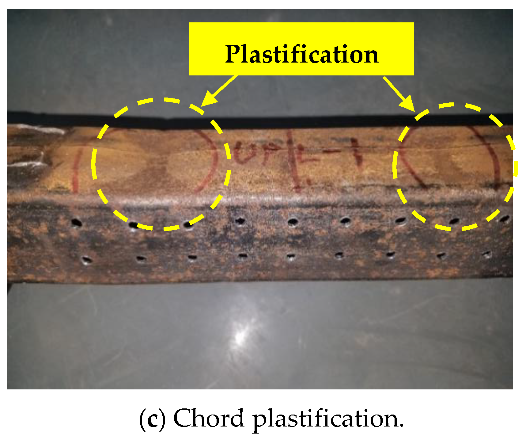
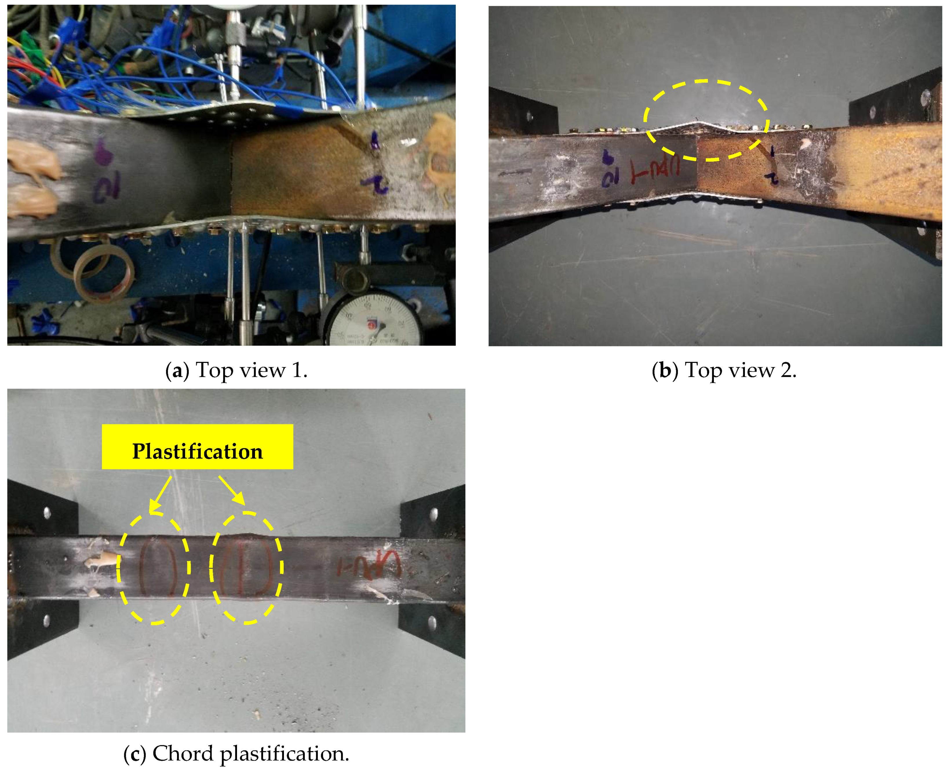
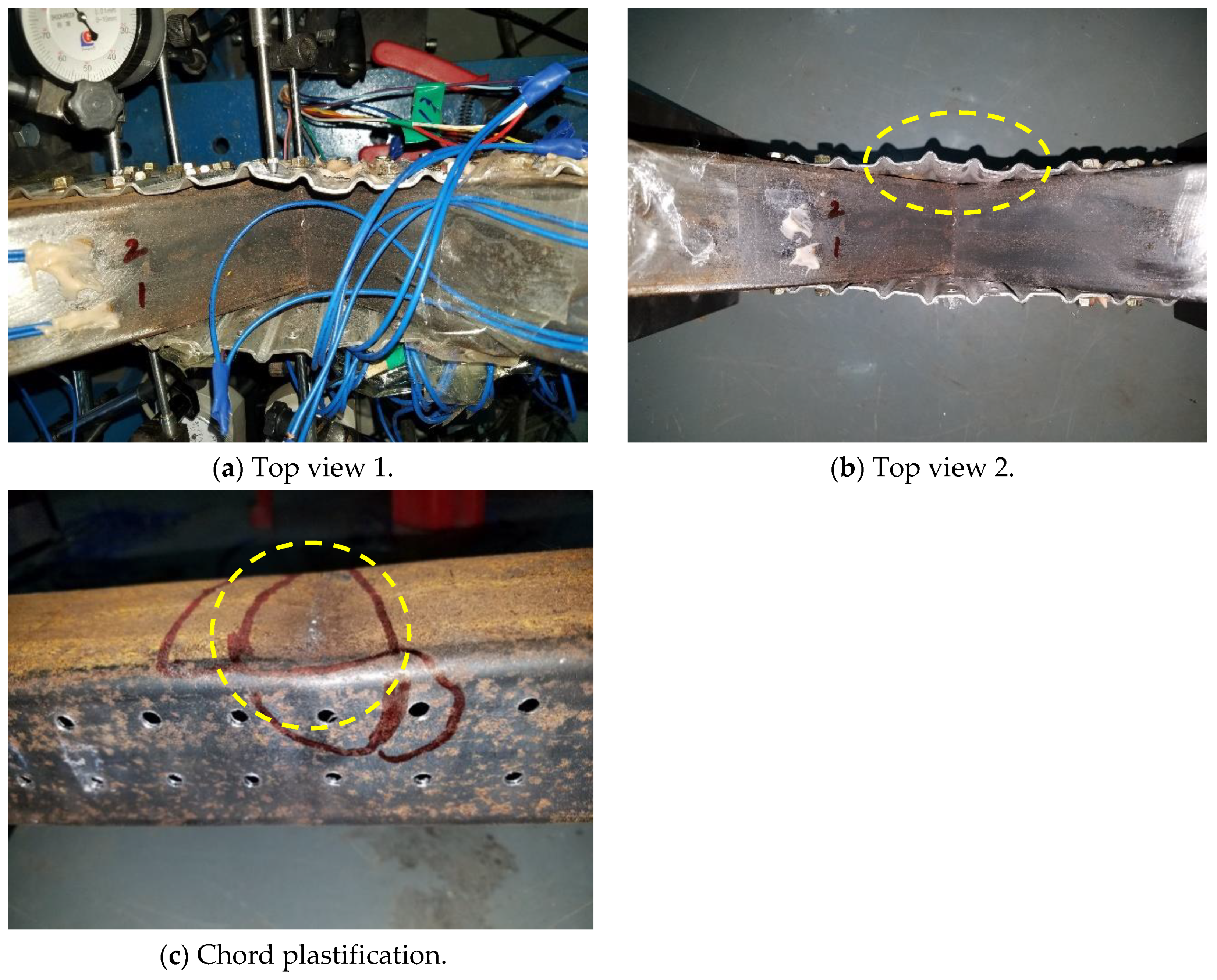
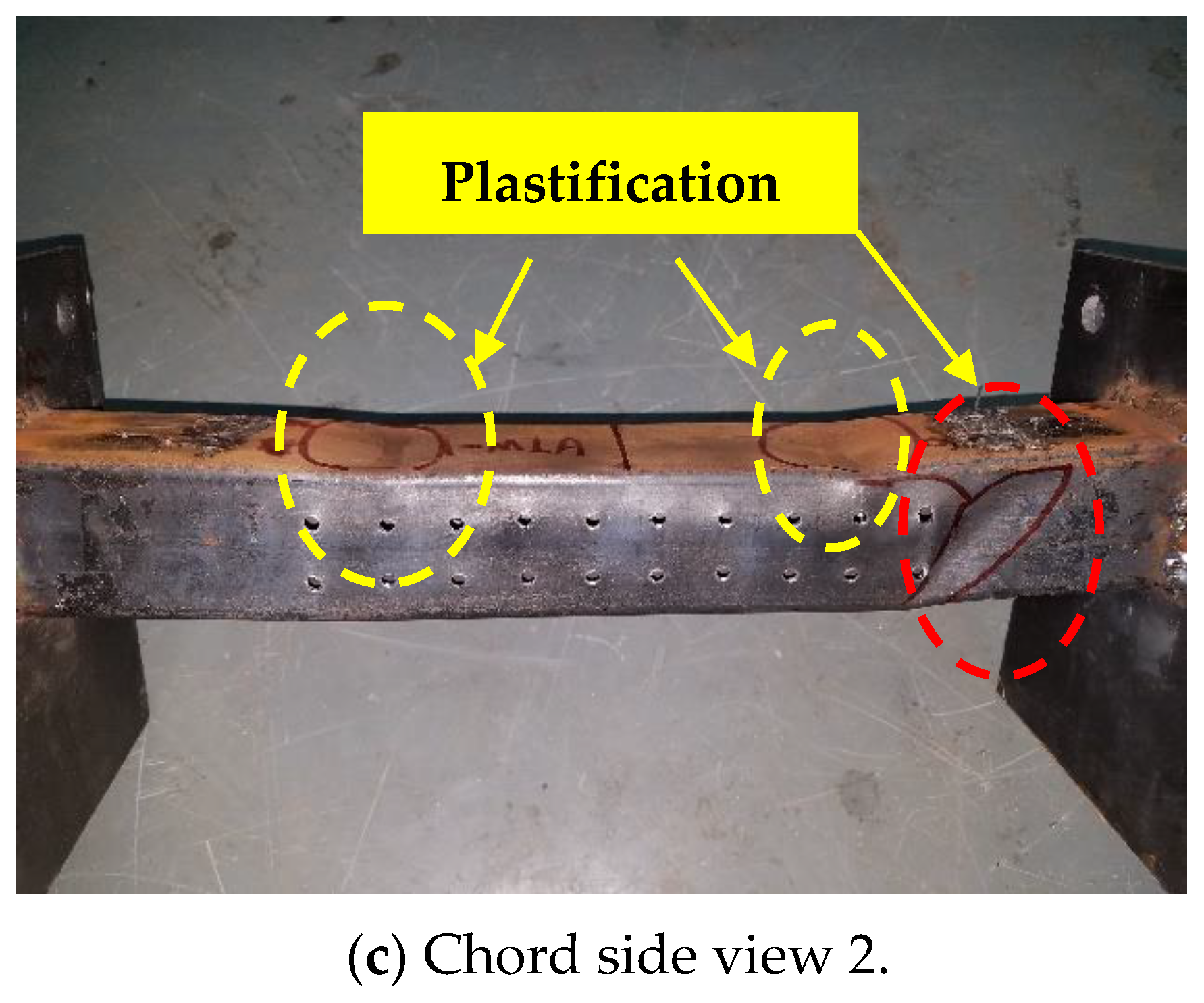
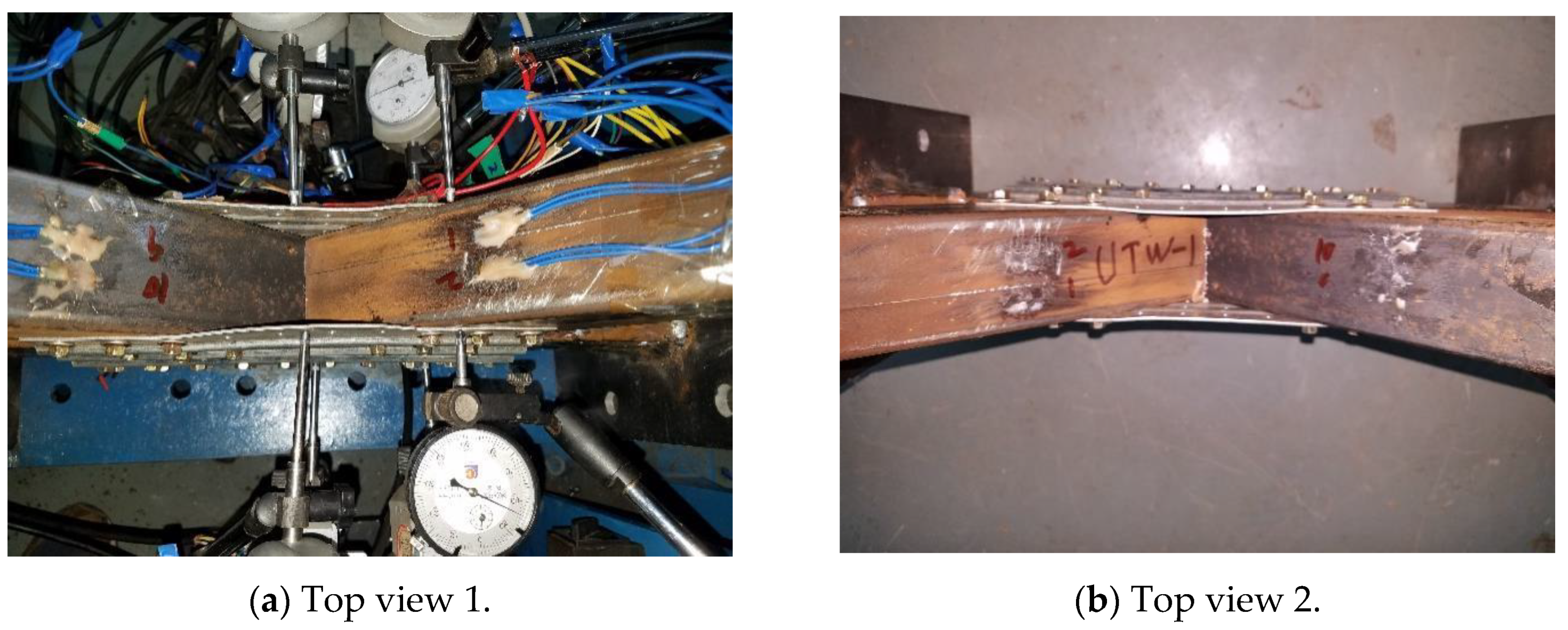
4.1. Failure Mode
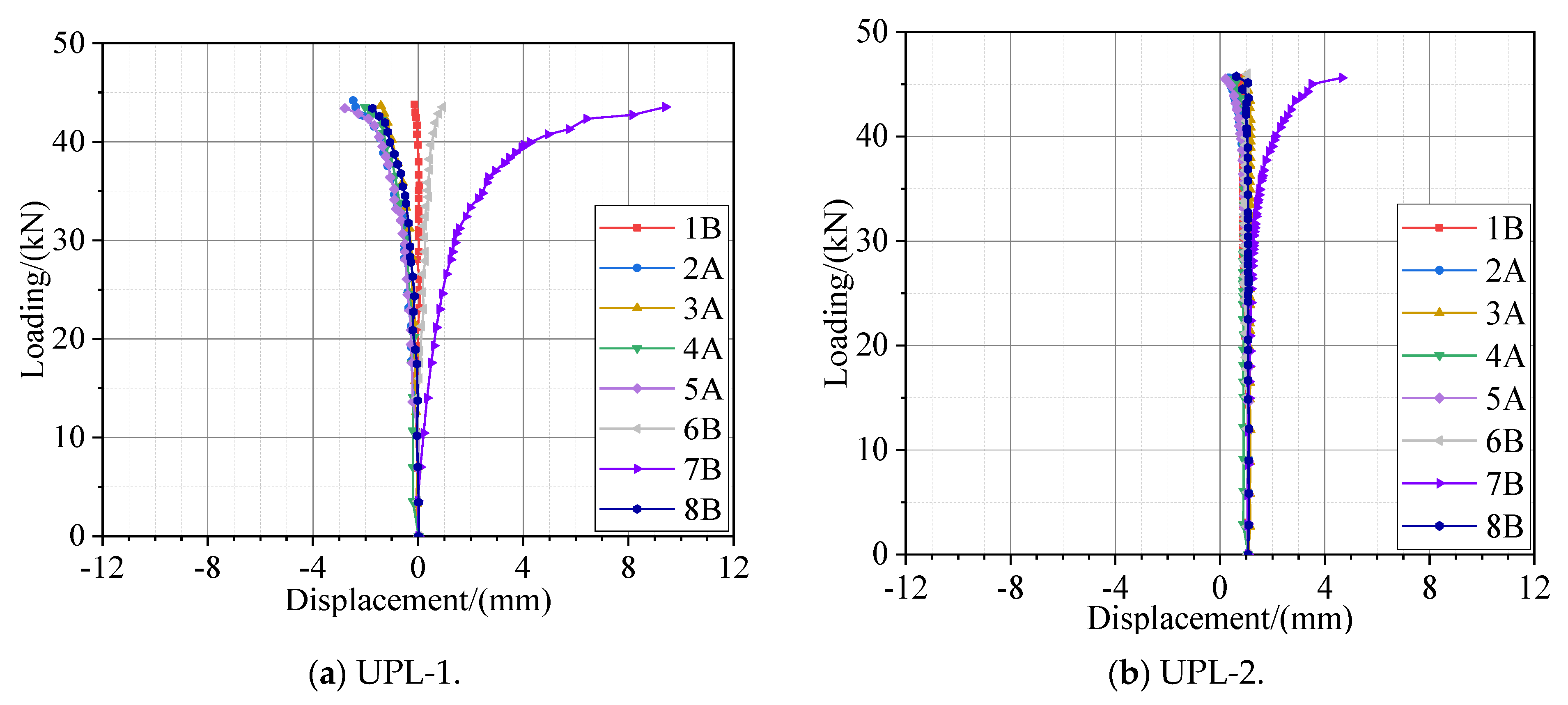
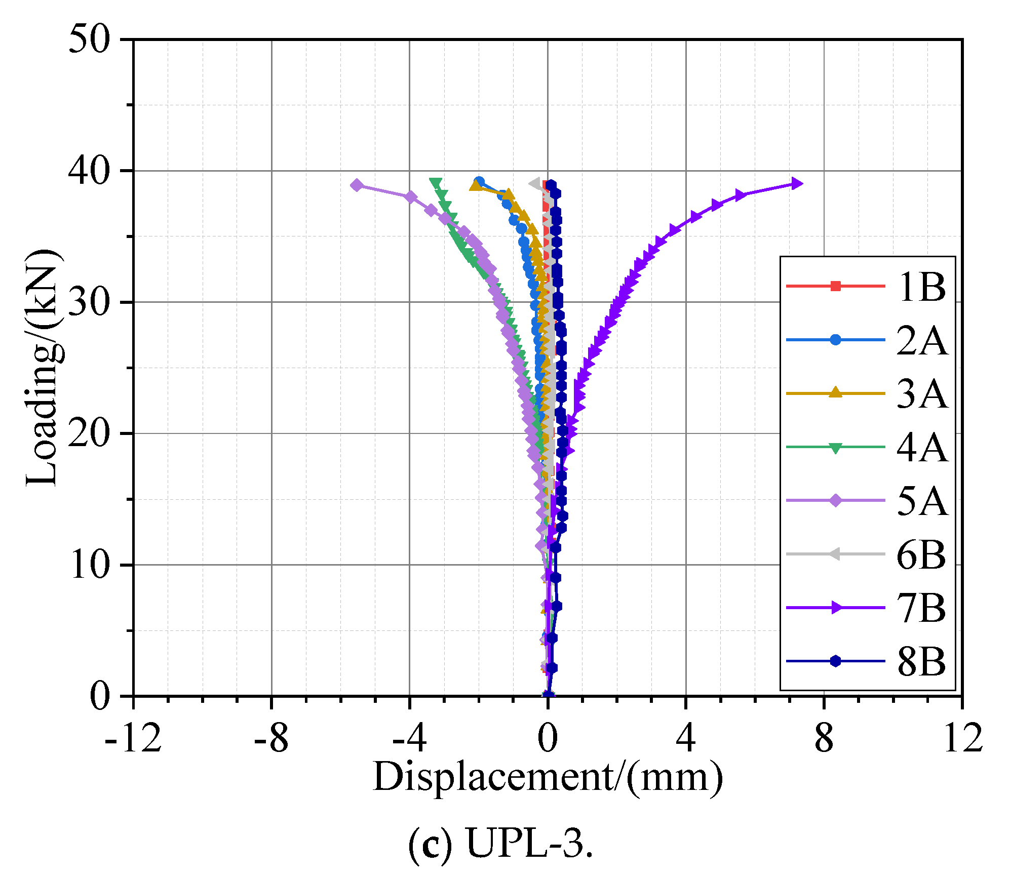
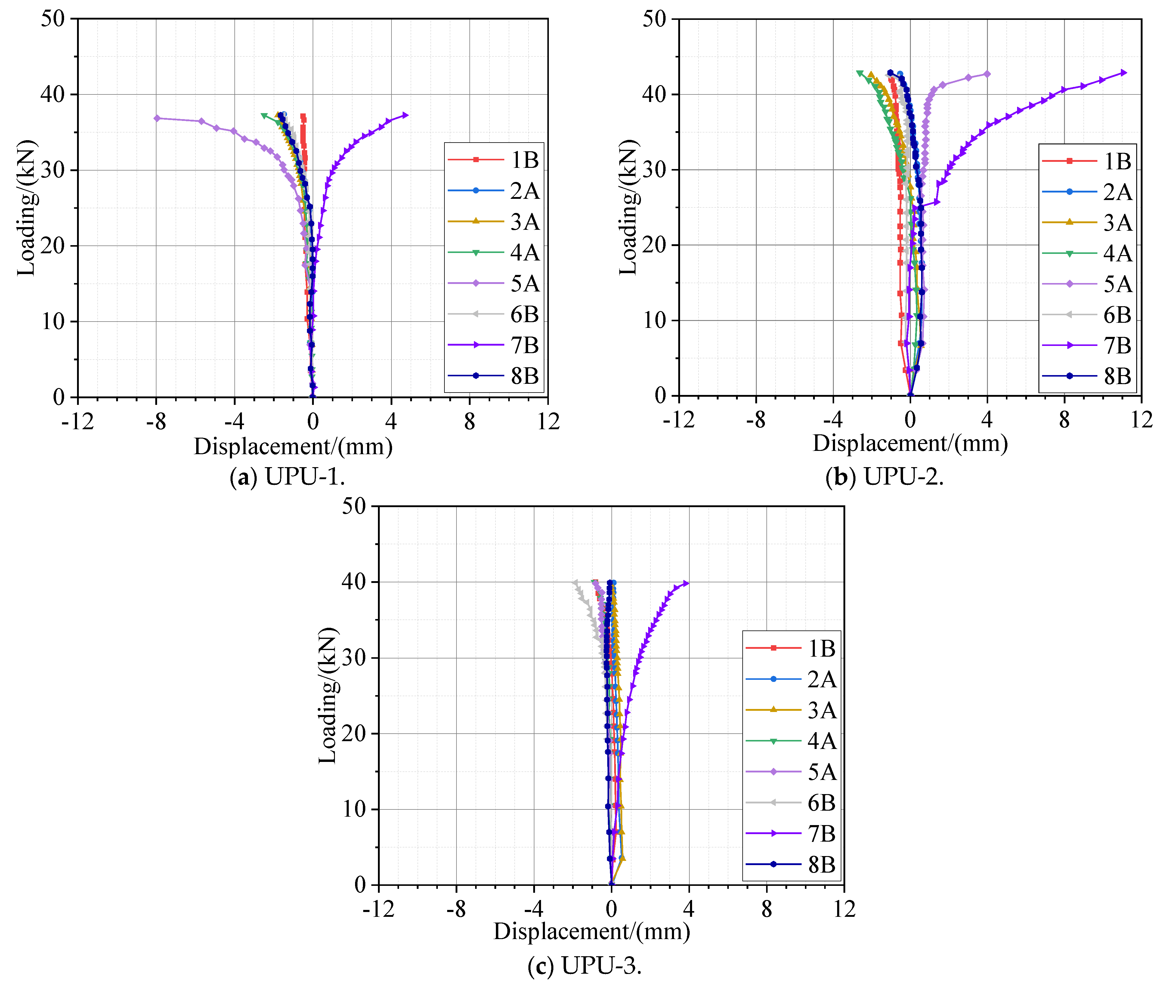
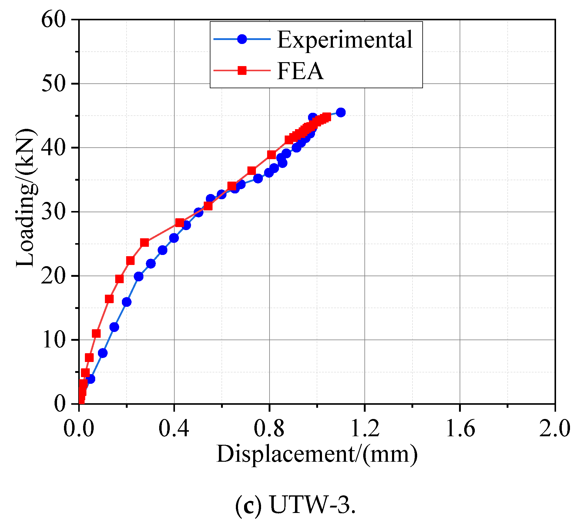
4.2. Loading-Displacement Curves
4.3. Ultimate Bearing Capacity
5. Finite Element Analyses of Specimens Using UTW Connector
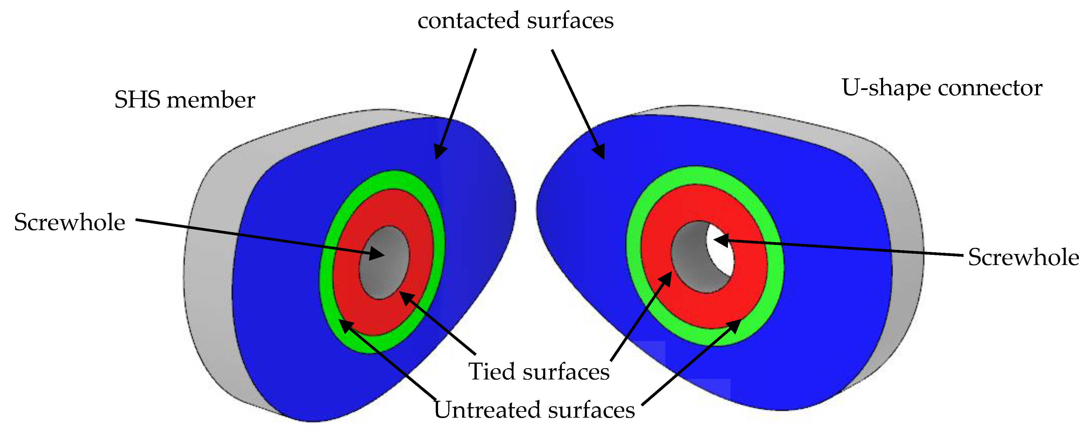
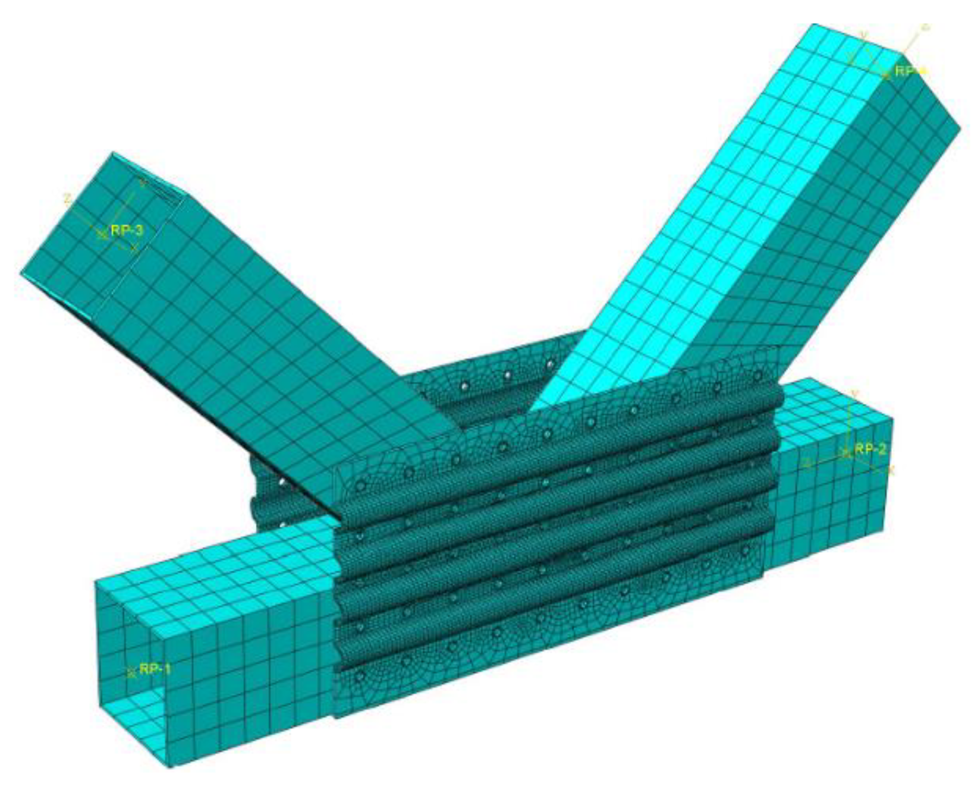
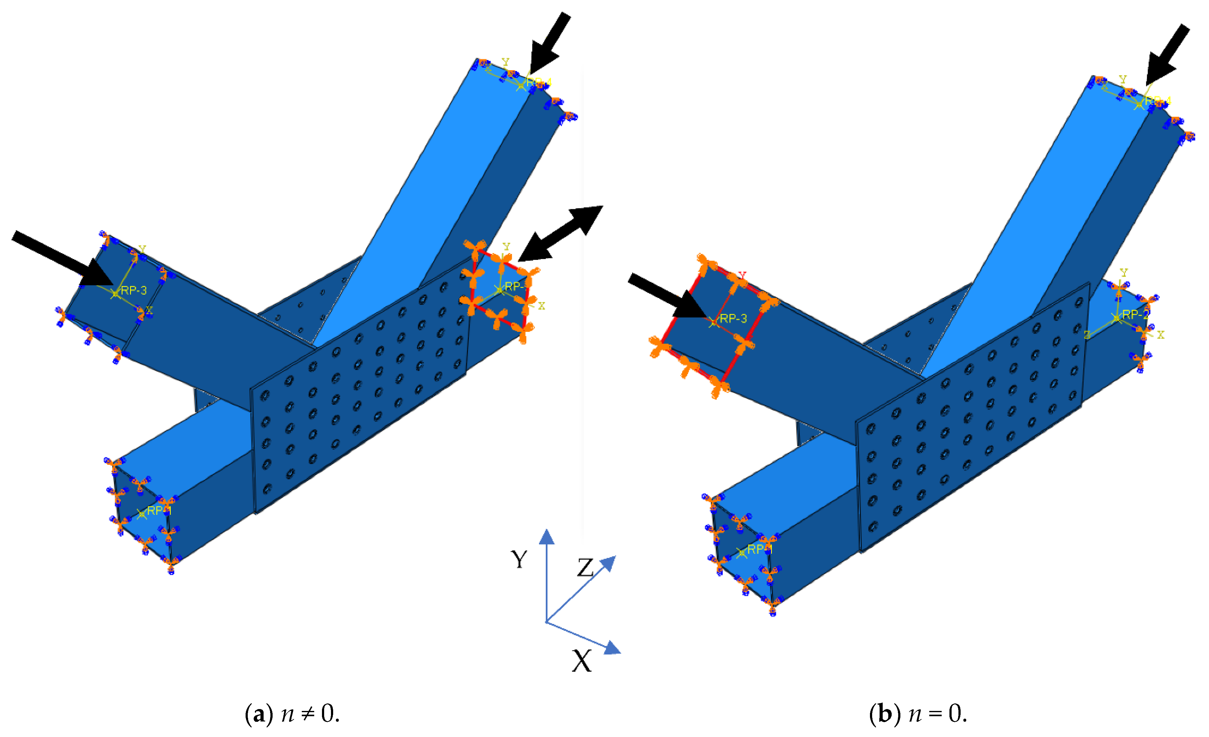
5.1. FE Modelling
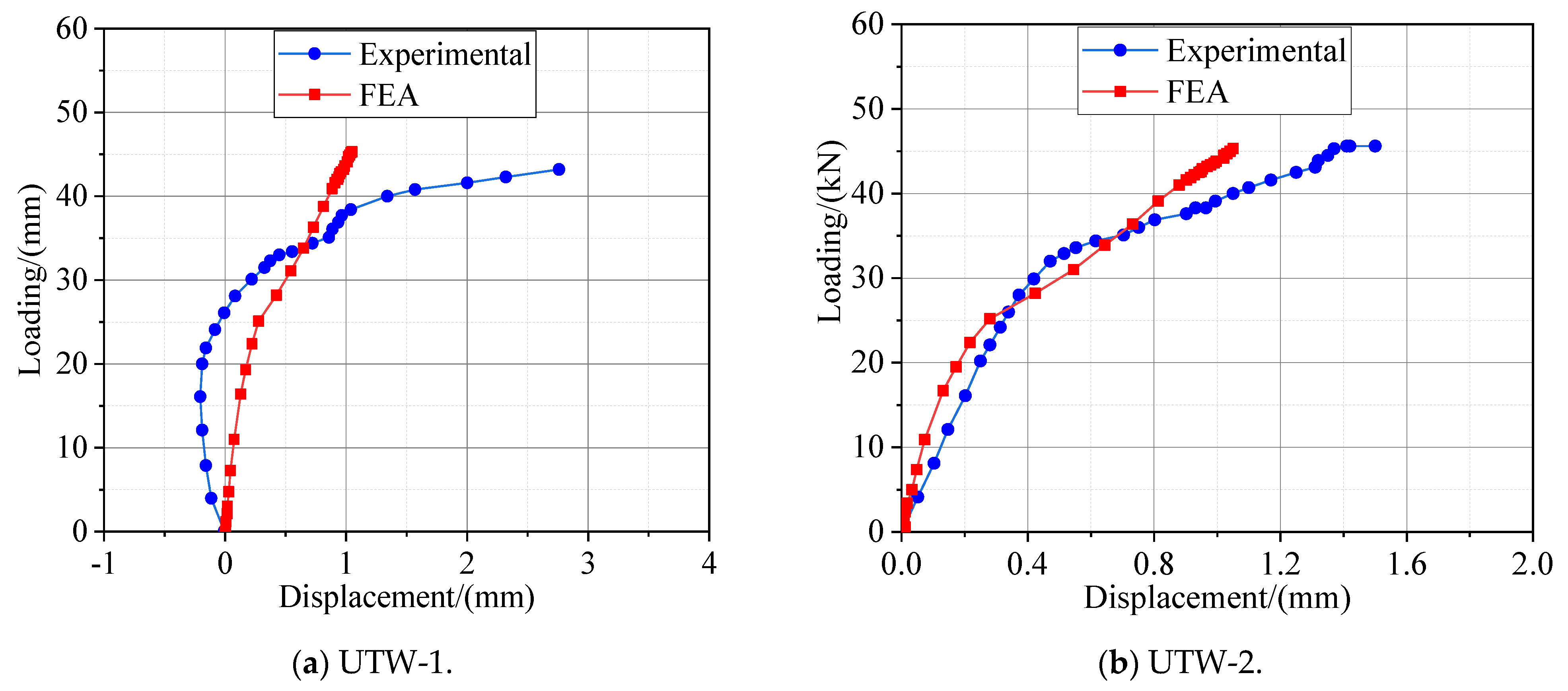
5.2. Validation of FE Modelling
5.3. Parametric Study
6. Conclusions
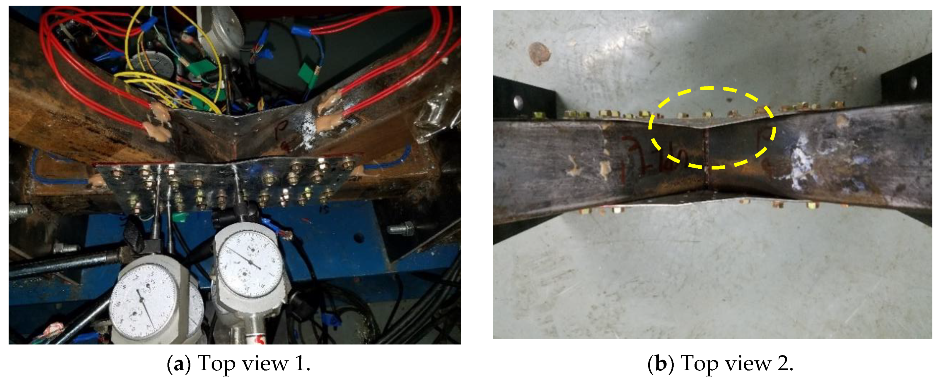
- (1)
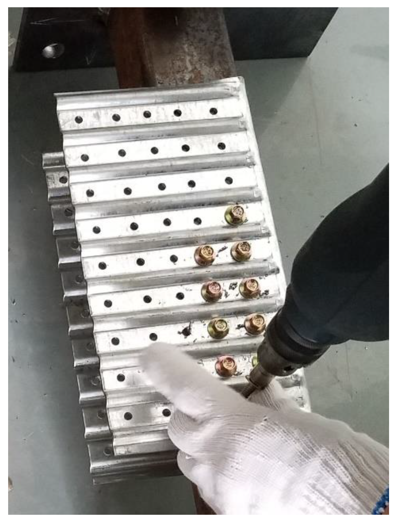
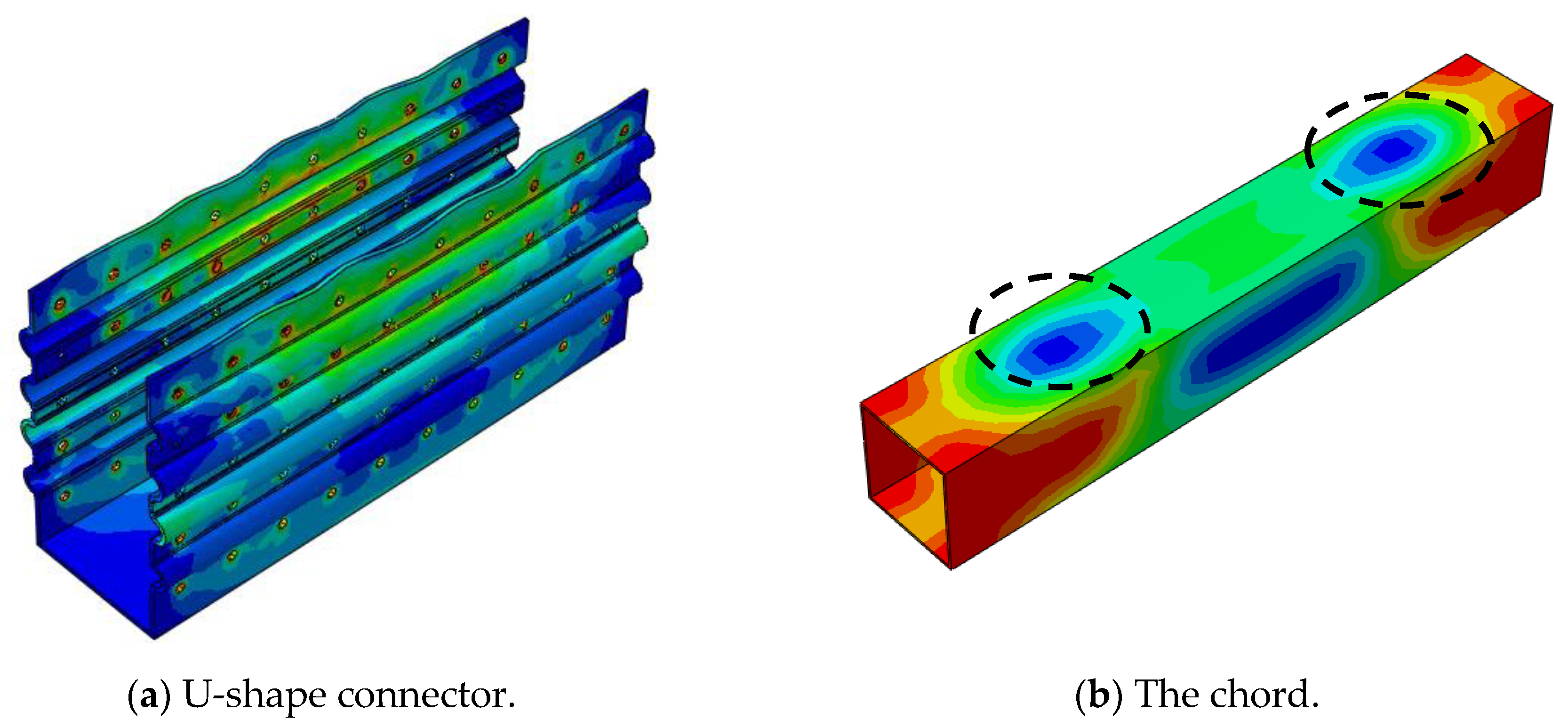
- Through investigating all K-joint specimens, it can be concluded that joint failure is governed by both the deformation of the U-shape connector and the chord local plastification. Besides, the U-shape connector and the wall of SHS members keep in contact tightly during the testing for all the specimens, and all the screws are sound.
- (2)
- Some patterns of stamping indentation fabricated on the U-shape connector may bring an unfavorable effect to the ultimate bearing capacity of the proposed K-joint, such as the stamping pits (UPU connector). For all the specimens investigated, those with the UTW connector, i.e., connectors with strip stamping grooves in the horizontal direction, generally have a higher ultimate bearing capacity and a much smaller connector deformation.
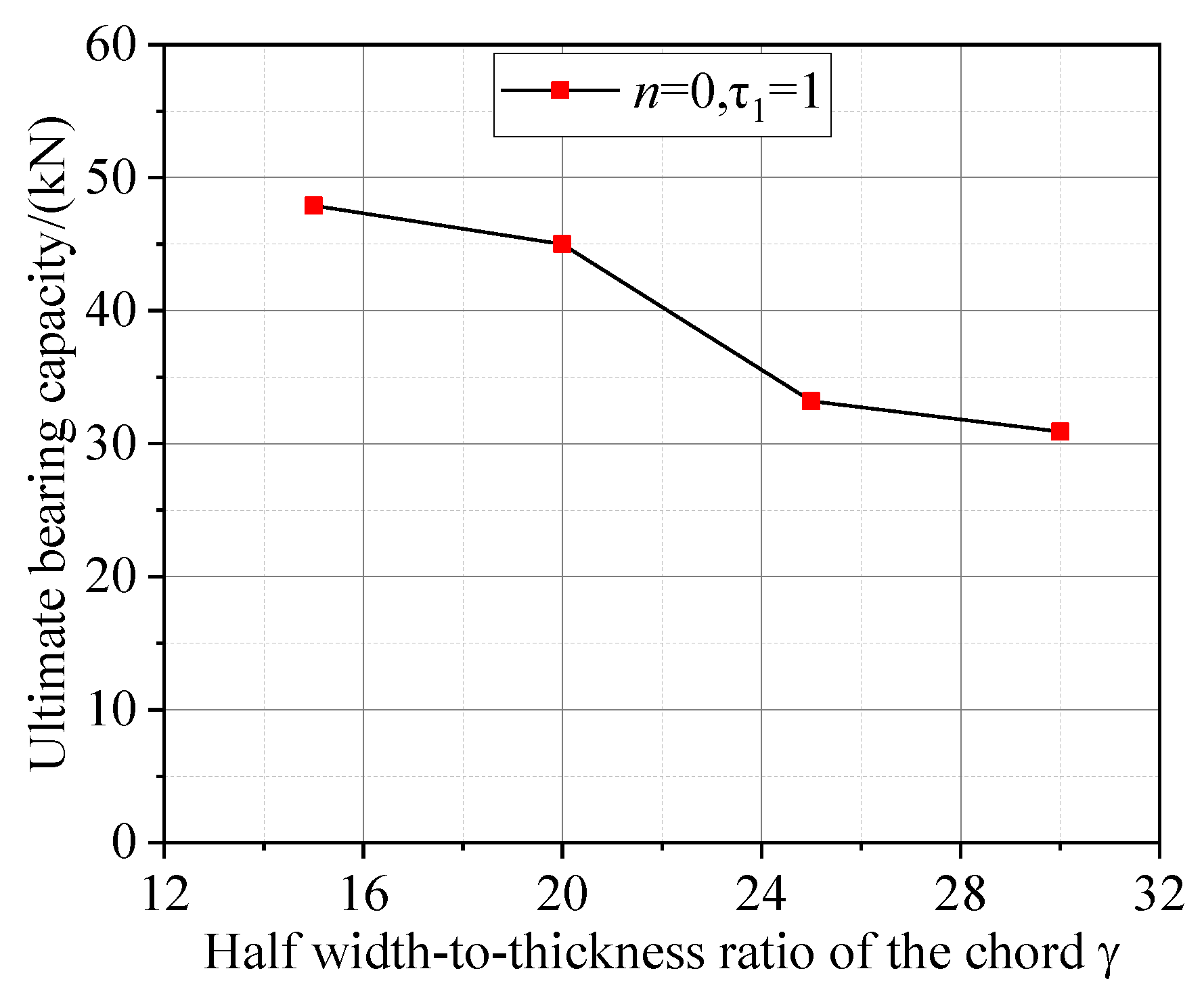
- (3)
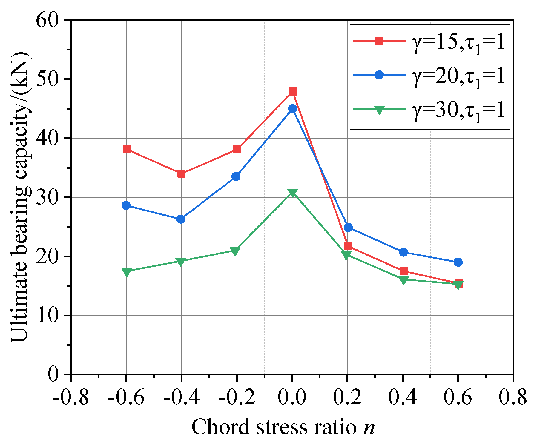
- Similar to the welded SHS joints, chord axial stresses, including the compression and the tension, can significantly reduce the ultimate bearing capacity of the proposed K-joint using the UTW connector. Moreover, a larger half width-to-thickness ratio of the chord γ will result in a smaller ultimate bearing capacity of the proposed K-joint using the UTW connector.
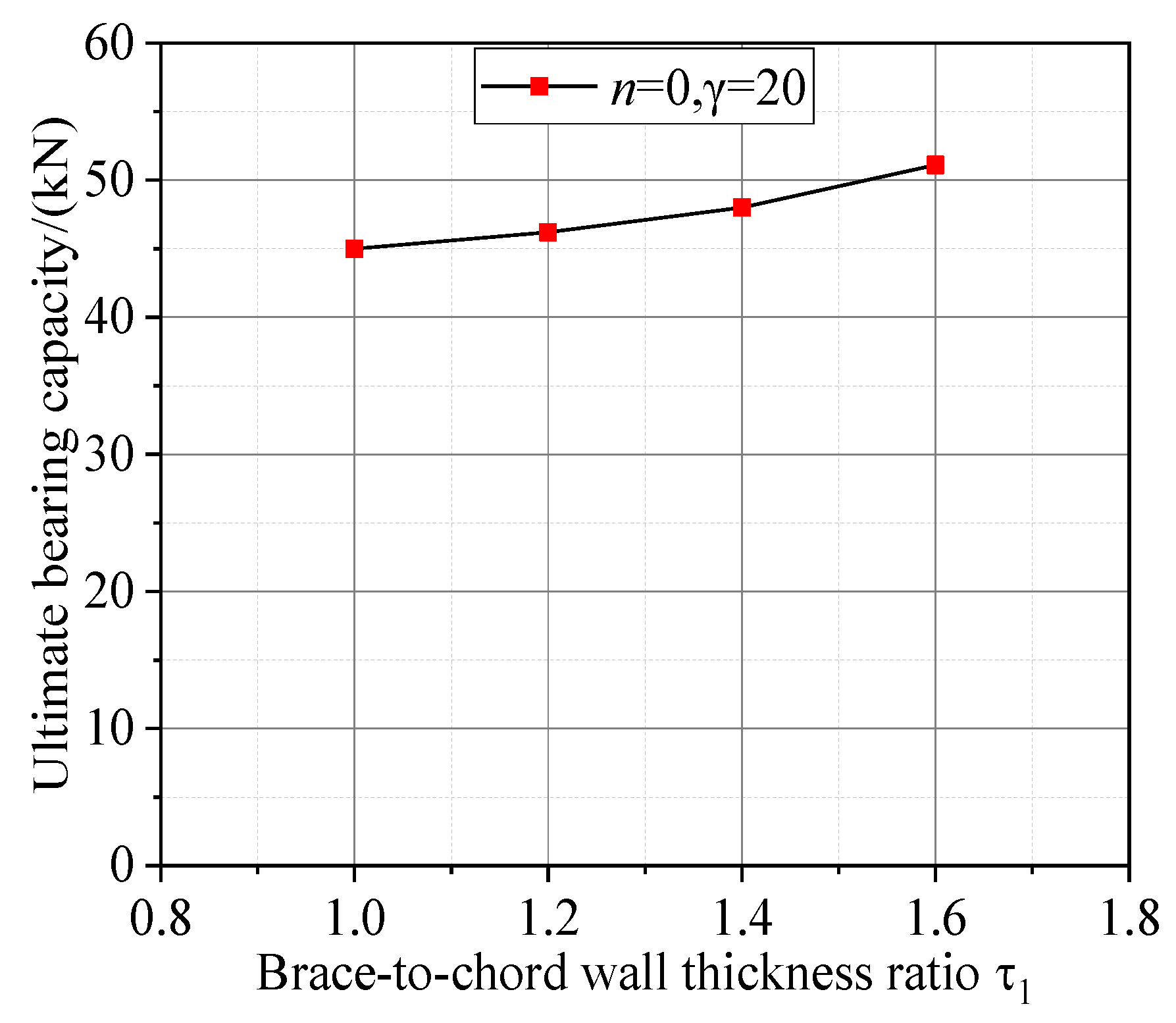
- (4)
- The ultimate bearing capacity of the K-joint using the UTW connector increases with the brace-to-chord wall thickness ratio τ1 when the chord section is fixed.
Author Contributions
Funding
Institutional Review Board Statement
Informed Consent Statement
Data Availability Statement
Acknowledgments
Conflicts of Interest
Nomenclature
| γ | Half width-to-thickness ratio of the chord |
| τ1 | Brace-to-chord wall thickness ratio |
| n | Chord stress divided by chord yield stress |
References
- Wardenier, J.; Paker, J.A.; Zhao, X.L.; van der Vegte, G.J. Hollow Sections in Structural Applications; CIDECT: Geneva, Switzerland, 2010. [Google Scholar]
- Mills, J.; LaBoube, R. Self-drilling screw joints for cold-formed channel portal frames. ASCE J. Struct. Eng. 2004, 130, 1799–1806. [Google Scholar] [CrossRef]
- Lee, Y.H.; Tan, C.S.; Mohammad, S. Review on cold-formed steel connections. Sci. World J. 2014, 2014, 951216. [Google Scholar] [CrossRef] [PubMed]
- Yan, W.; Mu, T.; Xie, Z.; Yu, C. Experimental investigation of typical connections for fabricated cold-formed steel trusses. Adv. Struct. Eng. 2019, 22, 141–151. [Google Scholar] [CrossRef]
- Li, Q.Y.; Young, B. Tests of cold-formed steel built-up open section members under eccentric compressive load. J. Constr. Steel Res. 2021, 184, 106775. [Google Scholar] [CrossRef]
- Zou, Y.; Zhou, X.; Shi, Y. Shear resistance of cold-formed thin-walled steel inter-story connections. J. Constr. Steel Res. 2021, 183, 106757. [Google Scholar] [CrossRef]
- Chen, X.; Blum, H.B.; Roy, K. Cold-formed steel portal frame moment-resisting joints: Behaviour, capacity and design. J. Constr. Steel Res. 2021, 183, 106718. [Google Scholar] [CrossRef]
- Zaharia, R.; Dubia, D. Stiffness of joints in bolted connected cold-formed steel trusses. J. Constr. Steel Res. 2006, 62, 240–249. [Google Scholar] [CrossRef]
- Öztürk, F.; Pul, S. Experimental and numerical study on a full scale apex connection of cold-formed steel portal frames. Thin Walled Struct. 2015, 94, 79–88. [Google Scholar] [CrossRef]
- Pouladi, P.; Ronaldson, J.; Clifton, G.C. Finite-element assisted design of eaves joint of cold-formed steel portal frames having single channel sections. Structures 2019, 20, 452–464. [Google Scholar] [CrossRef]
- Far, H.; Saleh, A.; Firouzianhaji, A. A simplified method to determine shear stiffness of thin-walled cold formed steel storage rack frames. J. Constr. Steel Res. 2017, 138, 799–805. [Google Scholar] [CrossRef]
- Song, L.; Yan, W.; Yu, C. Flexural behavior investigation of the CFS truss beams with self-piercing riveted connection. J. Constr. Steel Res. 2019, 156, 28–45. [Google Scholar] [CrossRef]
- Song, L.; Yan, W.; Zhang, X. Feasibility research on the application of self-piercing riveted connection in cold-formed steel structures. J. Constr. Steel Res. 2020, 168, 105957. [Google Scholar] [CrossRef]
- Wang, J.F.; Wang, W.Q.; Xiao, Y.; Guo, L. Cyclic behavior tests and evaluation of CFS truss composite floors. J. Build. Eng. 2020, 35, 101974. [Google Scholar] [CrossRef]
- Roy, K.; Lau, H.H.; Ting, T.C.H. Experiments and finite element modelling of screw pattern of self-drilling screw connections for high strength cold-formed steel. Thin-Walled Struct. 2019, 145, 106393. [Google Scholar] [CrossRef]
- Fahmy, A.S.; Swelem, S.M.; Mussttaf, H.H. Beam-column connections behavior of cold-formed steel members: New experimental configuration. KSCE J. Civil Eng. 2020, 24, 2147–2159. [Google Scholar] [CrossRef]
- Mathieson, C.; Roy, K.; Clifton, G.C. Failure mechanism and bearing capacity of cold-formed steel trusses with HRC connectors. Eng. Struct. 2019, 201, 109741. [Google Scholar] [CrossRef]
- Dizdar, Ç.; Baran, E.; Topkaya, C. Strength and stiffness of floor trusses fabricated from cold-formed steel lipped channels. Eng. Struct. 2019, 181, 437–457. [Google Scholar] [CrossRef]
- Phan, D.T.; Mojtabaei, S.M.; Hajirasouliha, I.H. Design and optimization of cold-formed steel sections in bolted moment connections considering bimoment. ASCE J. Struct. Eng. 2020, 146, 04020153. [Google Scholar] [CrossRef]
- Zagόrowska, M.G.; Galewska, E.U.; Deniziak, P. Experimental investigation of joint with positive eccentricity in CFS truss. Thin Walled Struct. 2020, 157, 106998. [Google Scholar] [CrossRef]
- Gan, J.C.; Lim, J.H.; Lim, S.K.; Lin, H.S. Experimental and numerical study on the effect of heel plate length and thickness on the structural integrity of cold-formed steel roof trusses. Int. J. Steel Struct. 2021, 21, 22–34. [Google Scholar] [CrossRef]
- Güldür, H.; Baran, E.; Topkaya, G. Experimental and numerical analysis of cold-formed steel floor trusses with concrete filled compression chord. Eng. Struct. 2021, 234, 111813. [Google Scholar] [CrossRef]
- Choo, Y.S.; Qian, X.D.; Wardenier, J. Effects of boundary conditions and chord stresses on static strength of thick-walled CHS K-joints. J. Constr. Steel Res. 2006, 62, 316–328. [Google Scholar] [CrossRef]
- Li, T.; Lie, S.T.; Cong, P.W. Effect of chord axial stresses on the static strength of cracked tubular T/Y-joints under out-of-plane and in-plane bending. Adv. Struct. Eng. 2019, 22, 1698–1710. [Google Scholar] [CrossRef]


| No. | UPL1 | UPL2 | UPL3 | UPU1 | UPU2 | UPU3 | ULW1 | ULW2 | ULW3 | UTW1 | UTW2 | UTW3 |
|---|---|---|---|---|---|---|---|---|---|---|---|---|
| L | 243 | 238 | 241 | 242 | 241 | 242 | 239 | 242 | 241 | 240 | 240 | 242 |
| H | 123.50 | 124 | 123.50 | 123 | 123 | 123 | 119 | 120 | 120 | 123 | 124 | 124 |
| B | 64 | 65 | 63 | 66 | 66 | 64 | 66 | 64 | 63 | 65 | 66 | 65 |
| t | 1.74 | 1.71 | 1.75 | 1.75 | 1.73 | 1.73 | 1.75 | 1.77 | 1.76 | 1.75 | 1.75 | 1.74 |
| t1 | / | / | / | 6 | 6 | 6 | 6 | 6 | 6 | 6 | 6 | 6 |
| a | 13 | 12.50 | 12.50 | 16.50 | 17 | 16.50 | 9 | 10 | 10.50 | 13 | 12 | 13 |
| b | 23.50 | 23 | 23 | 25 | 25 | 25 | 23.50 | 23 | 23 | 24 | 24 | 24 |
| c | 21.50 | 21.50 | 22 | 20.50 | 21 | 21 | 22 | 22 | 21 | 20.50 | 20.50 | 20 |
| d | 22.50 | 22 | 22 | 21.50 | 21 | 21.50 | 23 | 22.50 | 22.50 | 20 | 20 | 20 |
| e | 23 | 22.50 | 22.50 | 24 | 24 | 24 | 23 | 23 | 23 | 23.50 | 23.50 | 23 |
| f | 22.50 | 23 | 22.5 | 16.50 | 16 | 16 | 21.50 | 21 | 21 | 23.50 | 24 | 24 |
| a’ | 14 | 12 | 14.50 | 14 | 12 | 15 | 12 | 13.50 | 12.50 | 23 | 24 | 25 |
| b’ | 25 | 25 | 25 | 23.50 | 23.50 | 23 | 25 | 25 | 25.50 | 24 | 24 | 23.50 |
| c’ | 24.50 | 24 | 24.50 | 24.50 | 24.50 | 24.50 | 24 | 24.50 | 24 | 24.50 | 24 | 23.50 |
| d’ | 25 | 24.50 | 25 | 24.50 | 24.50 | 24 | 24.50 | 25 | 24.50 | 23 | 23.50 | 23 |
| e’ | 24 | 23.50 | 24 | 24 | 24.50 | 24.50 | 23.50 | 24 | 24 | 25 | 23 | 24 |
| f’ | 24.50 | 24 | 24 | 24.50 | 24.50 | 24 | 24 | 23.50 | 23.50 | 24 | 23.50 | 24 |
| g’ | 25 | 24.50 | 24.50 | 25 | 25 | 25 | 24.50 | 25 | 25 | 24 | 23.50 | 24 |
| h’ | 25 | 24.50 | 24 | 24.50 | 24.50 | 24.50 | 25 | 25 | 25 | 24 | 23.50 | 23.50 |
| i’ | 23 | 23 | 23 | 24 | 24 | 24 | 22 | 23 | 23 | 24 | 24 | 24 |
| j’ | 25 | 24.50 | 25 | 23 | 23 | 23 | 25 | 25 | 25 | 24 | 24.50 | 24.50 |
| k’ | 10.50 | 8 | 10 | 12.5 | 14 | 11 | 9.50 | 10.50 | 11 | / | / | / |
| R | 5 | 5 | 5 | 5 | 5 | 5 | 5 | 5 | 5 | 5 | 5 | 5 |
| R1 | / | / | / | 12 | 12 | 12 | / | / | / | / | / | / |
| Specimen No. | Thickness | Elastic Modulus | Yield Stress | Ultimate Stress | Elongation Rate (%) |
|---|---|---|---|---|---|
| (mm) | (GPa) | (MPa) | (MPa) | ||
| UP-1 | 1.79 | 172 | 280.10 | 372.67 | 27.10 |
| UP-2 | 1.78 | 180 | 275.46 | 402.83 | 27.30 |
| UP-3 | 1.79 | 176 | 286.52 | 355.56 | 31.80 |
| UP-4 | 1.79 | 175 | 273.20 | 380.33 | 32.70 |
| UP-5 | 1.79 | 182 | 290.14 | 376.57 | 25.10 |
| UP-6 | 1.79 | 175 | 274.32 | 386.23 | 3000 |
| XF-1 | 1.44 | 202 | 327.23 | 390.42 | 2300 |
| XF-2 | 1.47 | 216 | 350.20 | 360.56 | 2100 |
| XF-3 | 1.48 | 209 | 315.46 | 390.33 | 2300 |
| XF-4 | 1.50 | 194 | 344.87 | 400.01 | 2300 |
| XF-5 | 1.45 | 205 | 300.00 | 385.66 | 2200 |
| XF-6 | 1.50 | 210 | 331.97 | 380.45 | 2100 |
| Group No. | Specimen No. | Thickness of the Connector | Ultimate Bearing Capacity | The Average |
|---|---|---|---|---|
| (mm) | (kN) | (kN) | ||
| Group 1 | UPL1 | 1.74 | 43.40 | 42.60 |
| UPL2 | 1.71 | 45.60 | ||
| UPL3 | 1.75 | 38.90 | ||
| Group 2 | UPU1 | 1.75 | 37.10 | 39.90 |
| UPU2 | 1.73 | 42.70 | ||
| UPU3 | 1.73 | 39.90 | ||
| Group 3 | ULW1 | 1.75 | 44.80 | 42.40 |
| ULW2 | 1.77 | 40.00 | ||
| ULW3 | 1.76 | 42.40 | ||
| Group 4 | UTW1 | 1.75 | 43.20 | 44.50 |
| UTW2 | 1.75 | 45.60 | ||
| UTW3 | 1.74 | 44.60 |
| No. | γ | τ1 | n | Ultimate Bearing Capacity (kN) |
|---|---|---|---|---|
| 1 | 15 | 1.0 | −0.6 | 38.2 |
| 2 | 15 | 1.0 | −0.4 | 34.1 |
| 3 | 15 | 1.0 | −0.2 | 38.2 |
| 4 | 15 | 1.0 | 0.0 | 47.9 |
| 5 | 15 | 1.0 | 0.2 | 21.8 |
| 6 | 15 | 1.0 | 0.4 | 17.4 |
| 7 | 15 | 1.0 | 0.6 | 15.5 |
| 8 | 20 | 1.0 | −0.6 | 28.7 |
| 9 | 20 | 1.0 | −0.4 | 26.4 |
| 10 | 20 | 1.0 | −0.2 | 33.5 |
| 11 | 20 | 1.0 | 0.0 | 45.0 |
| 12 | 20 | 1.0 | 0.2 | 25.0 |
| 13 | 20 | 1.0 | 0.4 | 20.8 |
| 14 | 20 | 1.0 | 0.6 | 19.1 |
| 15 | 30 | 1.0 | −0.6 | 17.5 |
| 16 | 30 | 1.0 | −0.4 | 19.2 |
| 17 | 30 | 1.0 | −0.2 | 21.0 |
| 18 | 30 | 1.0 | 0.0 | 31.0 |
| 19 | 30 | 1.0 | 0.2 | 20.4 |
| 20 | 30 | 1.0 | 0.4 | 16.2 |
| 21 | 30 | 1.0 | 0.6 | 15.3 |
| 22 | 15 | 1.0 | 0.0 | 47.9 |
| 23 | 25 | 1.0 | 0.0 | 33.2 |
| 24 | 30 | 1.0 | 0.0 | 31.0 |
| 25 | 20 | 1.2 | 0.0 | 46.2 |
| 26 | 20 | 1.4 | 0.0 | 48.0 |
| 27 | 20 | 1.6 | 0.0 | 51.1 |
Publisher’s Note: MDPI stays neutral with regard to jurisdictional claims in published maps and institutional affiliations. |
© 2021 by the authors. Licensee MDPI, Basel, Switzerland. This article is an open access article distributed under the terms and conditions of the Creative Commons Attribution (CC BY) license (https://creativecommons.org/licenses/by/4.0/).
Share and Cite
Wang, X.; Yuan, X.; Zeng, H.; Li, T.; Liang, Y.; Gao, X.; Yu, Y. Bearing Capacity and Failure Mode of a Light-Steel Tubular K-joint Connected by a Novel U-shape Connector. Appl. Sci. 2021, 11, 8587. https://doi.org/10.3390/app11188587
Wang X, Yuan X, Zeng H, Li T, Liang Y, Gao X, Yu Y. Bearing Capacity and Failure Mode of a Light-Steel Tubular K-joint Connected by a Novel U-shape Connector. Applied Sciences. 2021; 11(18):8587. https://doi.org/10.3390/app11188587
Chicago/Turabian StyleWang, Xiaoping, Xun Yuan, Hui Zeng, Tao Li, Yang Liang, Xiaoming Gao, and Yinquan Yu. 2021. "Bearing Capacity and Failure Mode of a Light-Steel Tubular K-joint Connected by a Novel U-shape Connector" Applied Sciences 11, no. 18: 8587. https://doi.org/10.3390/app11188587
APA StyleWang, X., Yuan, X., Zeng, H., Li, T., Liang, Y., Gao, X., & Yu, Y. (2021). Bearing Capacity and Failure Mode of a Light-Steel Tubular K-joint Connected by a Novel U-shape Connector. Applied Sciences, 11(18), 8587. https://doi.org/10.3390/app11188587